WO2009147764A1 - Grommet - Google Patents
Grommet Download PDFInfo
- Publication number
- WO2009147764A1 WO2009147764A1 PCT/JP2008/073059 JP2008073059W WO2009147764A1 WO 2009147764 A1 WO2009147764 A1 WO 2009147764A1 JP 2008073059 W JP2008073059 W JP 2008073059W WO 2009147764 A1 WO2009147764 A1 WO 2009147764A1
- Authority
- WO
- WIPO (PCT)
- Prior art keywords
- inner cylinder
- grommet
- cylinder
- wall portion
- annular connecting
- Prior art date
Links
Images


Classifications
-
- B—PERFORMING OPERATIONS; TRANSPORTING
- B60—VEHICLES IN GENERAL
- B60R—VEHICLES, VEHICLE FITTINGS, OR VEHICLE PARTS, NOT OTHERWISE PROVIDED FOR
- B60R16/00—Electric or fluid circuits specially adapted for vehicles and not otherwise provided for; Arrangement of elements of electric or fluid circuits specially adapted for vehicles and not otherwise provided for
- B60R16/02—Electric or fluid circuits specially adapted for vehicles and not otherwise provided for; Arrangement of elements of electric or fluid circuits specially adapted for vehicles and not otherwise provided for electric constitutive elements
- B60R16/0207—Wire harnesses
- B60R16/0215—Protecting, fastening and routing means therefor
- B60R16/0222—Grommets
-
- B—PERFORMING OPERATIONS; TRANSPORTING
- B60—VEHICLES IN GENERAL
- B60R—VEHICLES, VEHICLE FITTINGS, OR VEHICLE PARTS, NOT OTHERWISE PROVIDED FOR
- B60R16/00—Electric or fluid circuits specially adapted for vehicles and not otherwise provided for; Arrangement of elements of electric or fluid circuits specially adapted for vehicles and not otherwise provided for
- B60R16/02—Electric or fluid circuits specially adapted for vehicles and not otherwise provided for; Arrangement of elements of electric or fluid circuits specially adapted for vehicles and not otherwise provided for electric constitutive elements
- B60R16/023—Electric or fluid circuits specially adapted for vehicles and not otherwise provided for; Arrangement of elements of electric or fluid circuits specially adapted for vehicles and not otherwise provided for electric constitutive elements for transmission of signals between vehicle parts or subsystems
-
- H—ELECTRICITY
- H01—ELECTRIC ELEMENTS
- H01B—CABLES; CONDUCTORS; INSULATORS; SELECTION OF MATERIALS FOR THEIR CONDUCTIVE, INSULATING OR DIELECTRIC PROPERTIES
- H01B17/00—Insulators or insulating bodies characterised by their form
- H01B17/56—Insulating bodies
- H01B17/58—Tubes, sleeves, beads, or bobbins through which the conductor passes
- H01B17/583—Grommets; Bushings
-
- H—ELECTRICITY
- H02—GENERATION; CONVERSION OR DISTRIBUTION OF ELECTRIC POWER
- H02G—INSTALLATION OF ELECTRIC CABLES OR LINES, OR OF COMBINED OPTICAL AND ELECTRIC CABLES OR LINES
- H02G3/00—Installations of electric cables or lines or protective tubing therefor in or on buildings, equivalent structures or vehicles
- H02G3/02—Details
- H02G3/04—Protective tubing or conduits, e.g. cable ladders or cable troughs
- H02G3/0462—Tubings, i.e. having a closed section
- H02G3/0468—Corrugated
-
- H—ELECTRICITY
- H02—GENERATION; CONVERSION OR DISTRIBUTION OF ELECTRIC POWER
- H02G—INSTALLATION OF ELECTRIC CABLES OR LINES, OR OF COMBINED OPTICAL AND ELECTRIC CABLES OR LINES
- H02G3/00—Installations of electric cables or lines or protective tubing therefor in or on buildings, equivalent structures or vehicles
- H02G3/22—Installations of cables or lines through walls, floors or ceilings, e.g. into buildings
Definitions
- the present invention relates to a grommet. Specifically, the grommet is assembled to a wire harness routed in an automobile, and is attached to a through hole of a vehicle body panel, and the wire harness is protected, waterproof, and dustproof at a through hole insertion portion.
- a grommet made of rubber or elastomer is attached to a wire harness routed from an engine room of an automobile into a vehicle compartment, and the grommet is attached to a through hole of a vehicle body panel that partitions the engine room and the vehicle compartment.
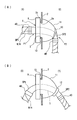
- the present applicant provides a grommet shown in FIG. 8A in Japanese Patent Application Laid-Open No. 2007-135253 (Patent Document 1).
- the grommet is provided with a body locking recess 102 on the outer peripheral surface on the large diameter side of the enlarged diameter cylindrical portion 100, and provided with closed surface portions 103A and 103B from the inner peripheral surface at the distal end on the larger diameter side of the expanded diameter cylindrical portion 100.
- a pair of semi-annular tube portions 104A and 104B project from the opposing central portions of the surface portions 103A and 103B.
- the small-diameter cylindrical portion 105 penetrates the central portion of the large-diameter cylindrical portion 1 from the small-diameter end side of the large-diameter cylindrical portion 100, and the inner portion is sandwiched between the pair of semi-annular cylindrical portions 104A and 104B. It protrudes as a tube 105a.
- the small-diameter cylindrical portion is not protruded outward from the small-diameter end side of the large-diameter cylindrical portion 100 and is provided so as to penetrate inside the enlarged-diameter cylindrical portion 100, the length of the grommet There is an advantage that can be shortened.
- the small-diameter cylindrical portion 105 spreads in an elliptical shape, and in a state where the tape T is wound around the outer peripheral surfaces of the pair of outer semicircular cylindrical portions 104A and 104B.
- the semi-annular tube portions 104A and 104B are also elliptical.
- the closed surface portions 103A and 103B connected to the bases of the semi-annular tube portions 104A and 104B are also pulled as shown in FIG. 9A.
- the slits between the facing surfaces of the closed surface portions 103A and 103B are widened to form a gap C, and the outer shape of the enlarged diameter cylindrical portion 100 connected to the closed surface portions 103A and 103B is also deformed.
- the vehicle body locking concave portion 102 formed on the outer peripheral surface of the enlarged diameter cylindrical portion 100 also has an elliptical shape and does not closely adhere to the through hole of the vehicle body panel to be locked. In this state, water leakage may occur through the through-hole of the vehicle body panel.
- the wire harness W / H is contracted in a state where the tape T is wound around the outer peripheral surfaces of the semi-annular cylindrical portions 104A and 104B and wound into an elliptical shape as shown in FIG. 9A, the vehicle body locking recess 102 may be deformed through the closed surface portions 103A and 103B, and water leakage may occur. Further, even when the wire harness W / H wound with the semi-annular tube portions 104A and 104B and the tape T is suddenly refracted as shown in FIG. The stop recess may be deformed and water leakage may occur.
- the present invention has been made in view of the above-described problems, and improves the water-stopping property so as not to generate a gap in the fixing portion between the small-diameter cylindrical portion that penetrates the grommet in close contact with the wire harness. It is an object of the present invention to improve the sealing performance by preventing a gap from being generated in the fixing portion between the grommet and the wire harness even when bent and preventing the vehicle body locking recess from being lifted by bending.
- the present invention is a grommet made of an elastic body that is externally attached to a wire harness that is inserted into a through hole provided in a vehicle body and is locked to the vehicle body, An inner cylinder penetrating through the wire harness of the wire harness; and An annular connecting portion protruding from the outer peripheral surface of the inner cylinder; An outer cylinder that is continuous with the outer peripheral end of the annular coupling portion and is concentric with the inner cylinder, The outer cylinder has the annular connecting portion and the thick wall portion continuous, the inclined wall portion having a diameter reduced to the thick wall portion is continued, and the vehicle body is locked to the outer peripheral surface of the boundary between the thick wall portion and the inclined wall portion.
- a recess is provided in an annular shape,
- a grommet characterized in that the annular connecting portion is thin and bent in a V shape from an inner peripheral end connected to the outer periphery of the small-diameter inner cylindrical portion to an outer peripheral end connected to the inner periphery of the outer cylinder. providing.
- the V-shaped protruding direction of the annular connecting portion is opposite to the extending direction of the inclined wall portion of the outer cylinder. This is because when protruding to the inclined wall portion side, when inserting the grommet into the through hole of the vehicle body panel, the inclined wall portion is bent inwardly and inserted, so that the annular connecting portion protrudes inward, This is because it obstructs the deformation of the inclined wall portion and the reduction of the insertion force of the grommet is impaired.
- the V-shaped angle of the annular connecting portion is 40 to 70 degrees
- the length of the annular connecting portion is a radial dimension between the inner peripheral surface of the inner cylinder and the outer peripheral surface of the outer cylinder. It is preferable that the thickness is 1.5 to 4 times, and the thickness of the annular connecting portion is equal to or less than the thickness of the inner cylinder and the outer cylinder.
- the V-shaped angle of the annular connecting portion is set, the length can be increased, and when the inner cylinder is bent due to the bending of the wire harness, the amount of absorption of the bending is increased and the outer cylinder is increased. The transmission of bends can be cut off. Further, if the annular connecting portion is made thin, bending absorption can be easily performed.
- the grommet according to the present invention has an annular coupling portion that connects the inner cylinder and the outer cylinder that allow the wire harness to closely pass therethrough and is bent into a V shape. This can be dealt with only by changing the bending angle of the part, and the inner cylinder can be tightly attached to the wire harness and fixed with tape. Further, even when the inner cylinder is deformed by bending the wire harness, the annular connecting portion contracts and expands to follow, and the deformation of the inner cylinder can be absorbed before reaching the outer peripheral side continuous with the outer cylinder. Therefore, it is possible to suppress / prevent the load such as pulling and compression from being applied to the outer cylinder.
- the vehicle body locking recess formed on the outer peripheral surface of the outer cylinder can be prevented from being deformed to maintain a circular shape, and the vehicle body locking recess can be prevented from rising. Therefore, the vehicle body locking recess can be brought into close contact with the periphery of the through hole of the vehicle body panel without being displaced, and the sealing performance can be improved and the occurrence of water leakage can be reliably prevented.
- the annular connecting portion protrudes from the outer periphery of the lengthwise intermediate portion sandwiched between the pushing side and the drawing side of both ends of the inner tube, and the thickness of the outer tube is formed at the outer peripheral end of the connecting portion.
- the inner circumferential surface of the outer wall of the outer cylinder is separated from the outer circumferential surface of the inner cylinder with a space therebetween, and the drawer side of the inner cylinder protrudes outward from the inclined wall section. It is preferable.
- a leading end side cylinder portion extending in parallel with the axial direction of the inner cylinder, and the separation between the inner peripheral surface of the leading end cylinder portion and the outer peripheral surface of the inner cylinder. You may open a space.
- the grommet separates the inner cylinder through which the wire harness is brought into close contact with the outer cylinder provided with the vehicle body locking recess with a large space on the drawing end side of the wire harness.
- the inner cylinder through which the wire harness is brought into close contact is a cylinder that is not divided in half.
- the tube can be brought into close contact with each other, and the sealing performance at the portion fixed to the wire harness can be improved.
- a pushing rib is projected from the inclined portion of the annular connecting portion toward the inner surface of the inclined wall portion of the outer cylinder, and the pushing rib is pressed against the inclined wall portion to transmit the pushing force. is doing.
- push ribs project from the annular connecting part, and the push ribs are pressed against the inner peripheral surface on the drawer side of the inclined wall part, and the pushing force is transmitted to the inclined wall part via the push rib to insert the grommet. Workability is improved. It is preferable to provide the pushing rib continuously on the entire circumference because the pushing force transmitted to the inclined wall portion can be applied uniformly. Further, it is preferable that the thickness of the push rib is 2 to 4 times the thickness of the annular connecting portion, and is larger than the thickness of the inclined wall portion.
- the grommet of the present invention is not limited to the detachable type grommet, and can be suitably used for a grommet of a type in which the small-diameter end of the inclined wall portion is connected to the inner cylinder via an annular connecting portion.
- the inner cylinder is formed of a first inner cylinder and a second inner cylinder which are divided by a grommet drawer side and a push-in side, and the small diameter end of the inclined wall portion of the outer cylinder is a drawer side.
- the second inner cylinder on the pushing side is connected to the outer cylinder via the annular connecting portion, and the annular connecting portion has a diametrically divided end, which is 2
- the split second inner cylinder protrudes and the annular coupling portion is bent into a V shape.
- the stepped ridges in the axial direction protrude from the outer peripheral surface of the inclined wall portion of the outer cylinder at intervals in the circumferential direction.
- the contact area is reduced and the insertion force is reduced.
- the inner cylinder through which the wire harness is brought into close contact and the outer cylinder provided with the vehicle body locking recess are connected via the annular connecting portion bent in a V shape.
- the deformation can be absorbed by changing the bending angle of the annular coupling portion, and the deformation of the vehicle body locking recess can be absorbed and absorbed by the transmission of the deformation to the outer cylinder. Lifting can be prevented and water stoppage performance can be improved.
- the change in the V-shaped angle of the annular coupling portion can follow the increase and decrease of the diameter of the wire harness, and in this case also, the watertight performance is ensured without affecting the outer cylinder provided with the vehicle body locking recess. be able to.
- FIG. 1st embodiment of this invention is shown, (A) is the perspective view seen from the drawer side, (B) is the perspective view seen from the pushing side. It is a side view of the drawer side of a grommet.
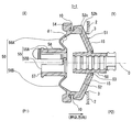
- FIG. 3 is a sectional view taken along line III-III in FIG. 2.
- FIG. 6 is a sectional view taken along line VI-VI in FIG. 2. It is sectional drawing which shows the state which made the grommet penetrate the wire harness and was attached to the vehicle body.
- (A) and (B) are schematic diagrams when the wire harness is bent. It is sectional drawing of the grommet of 2nd embodiment.
- (A) (B) is drawing which shows the conventional grommet.
- (A)-(C) are drawings explaining the problem.
- FIG. 1 to 6 show a first embodiment of the grommet of the present invention.
- the grommet 1 is attached to a wire harness W / H that is routed from the engine room (X) of the automobile to the vehicle compartment (Y) through the through hole 3 provided in the vehicle body panel 2. It is fixed to the periphery of the hole 3 and attached to the vehicle body.
- the grommet 1 is a one-motion type grommet that is attached to the vehicle body through the through hole 3 by pushing the grommet 1 from the engine room side.
- One end of the grommet 1 is a pushing side P1, and the other end is a drawing side P2.
- the grommet 1 is integrally formed of rubber or elastomer.
- the grommet 1 of the first embodiment is a separation type in which a space is provided between the small diameter end side of the inclined wall portion and the inner cylinder.
- the grommet 1 has a small-diameter inner cylinder 5 that penetrates the wire harness W / H in close contact with each other, and an outer peripheral surface 5a in the middle in the length direction sandwiched between the pushing side 5P1 and the drawing side 5P2 at both ends of the inner cylinder 5.
- an outer cylinder 8 having a large diameter continuous with the outer periphery of the annular coupling portion 6.
- the outer cylinder 8 is concentric with the inner cylinder 5 and is located with a space in the middle portion of the inner cylinder 5 in the length direction, and is located on both the pushing side P1 and the drawing side P2 on both sides of the outer cylinder 8 in the length direction.
- the cylinder 5 protrudes.
- the outer cylinder 8 extends from a continuous position with the outer periphery of the annular connecting portion 6 to the extraction side P2, and is provided with a thick portion 9 provided at the continuous position, and is continuously contracted to the extraction side P2 with the thick portion 9.
- the inclined wall portion 11 is extended.
- a vehicle body locking recess 10 is provided at the boundary between the thick wall portion 9 and the large-diameter end of the inclined wall portion 11 so as to open annularly on the outer peripheral surface.
- the leading end side cylinder portion 12 extending in parallel with the axial direction of the inner cylinder 5 is connected to the small diameter end of the inclined wall portion 11.
- the space between the inner peripheral surface of the leading end side cylinder portion 12 and the outer peripheral surface 5a of the inner cylinder 5 is separated by a space S. That is, the outer periphery of the inner cylinder 5 is formed in a shape surrounded by the small diameter end side of the outer cylinder 8 with a space S, and the drawer side 5P2 of the small diameter cylinder portion 5 is protruded outward from the outer cylinder 8.
- the radial dimension d1 of the space S is 1/2 to 3/2 of the radius d2 of the inner cylinder 5, as shown in FIG. 3, and is 3/4 in this embodiment.
- the length L1 of the leading end side cylinder portion 12 facing the outer peripheral surface 5a of the inner cylinder 5 across the space S varies depending on the size of the grommet 1, but is about 5 mm to 15 mm.
- the annular connecting portion 6 that connects the outer cylinder 8 and the inner cylinder 5 is moved to the pushing side P ⁇ b> 1 from the inner peripheral end 6 b continuous with the outer peripheral surface 5 a of the inner cylinder 5. It is bent in a V shape and protrudes.
- the outer peripheral end 6 a of the annular connecting portion 6 is positioned on the pushing side P ⁇ b> 1 from the inner peripheral end 6 b and is connected to the thick portion 9 of the outer cylinder 8.
- the V-shaped projecting direction of the annular coupling portion 6 is a pushing side P ⁇ b> 1 opposite to the extending direction of the inclined wall portion 11 of the outer cylinder 8. Further, the V-shaped angle ⁇ 1 of the annular connecting portion 6 is 40 to 70 degrees, and ⁇ 1 is 60 degrees in the present embodiment.
- the length of the annular connecting portion 6 from the inner peripheral end 6b to the outer peripheral end 6a is 1.5 to 4 times the radial dimension between the inner peripheral surface of the inner cylinder 5 and the outer peripheral surface of the outer cylinder 6, and this embodiment The form is 2.5 times.
- the annular connection 6 is provided with flat portions 6e and 6f perpendicular to the axial direction without bending into two V-shapes facing each other in the orthogonal direction.
- the through holes 31 and 32 which penetrate the opener cable and the water supply hose are provided in the parts 6e and 6f, respectively.
- the wall thickness t3 of the annular connecting portion 6 is less than the wall thickness t4 of the inner cylinder 5 to facilitate bending.
- the angle ⁇ 2 of the inner peripheral end 6b of the annular connecting portion 6 that is connected to the outer peripheral surface 5a of the inner cylinder 5 at an angle is set to 20 degrees to 30 degrees.
- the annular connecting portion 6 is provided with a bent portion 6d bent toward the inclined wall portion 11 at an inclined portion between the inner peripheral end 6b and the V-shaped protruding end 6c.
- a thick push rib 18 projects toward the inclined wall portion 11 at the bent portion 6d. As shown in FIG. 4, the push rib 18 is continuous in the circumferential direction, and is divided at the portion where the opener cable and the inner pipes 28 and 29 for the water supply hose are arranged.
- the thickness t5 of the push rib 18 is increased to be 2 to 4 times the wall thickness t3 of the annular connecting portion 6, and is larger than the wall thickness t1 of the inclined wall portion 11, and is approximately the same thickness as the thick portion 11. It is said.
- the thickness of the push rib 18 is that the protruding end 18a of the push rib 18 abuts against the inner peripheral surface of the inclined wall portion 11 during the insertion operation of pushing the grommet 1 into the through hole 3 of the vehicle body panel 2, and the pushing force is increased. This is because the outer cylinder 8 has a role to transmit.
- the protruding end 18 a of the push rib 18 is brought close to the protruding end 18 a and the inner peripheral surface of the inclined wall portion 11 so as to contact the inner peripheral surface of the inclined wall portion 11. ing.
- the sound insulation space B surrounded by the push rib 18, the inner cylinder 5, the annular coupling portion 6, and the outer cylinder 8 can be formed.
- the push rib 18 protrudes with a slight inclination in the outer diameter direction, and the protruding end 18 a is opposed to the inner peripheral surface on the small diameter end side of the inclined wall portion 11 continuous with the leading end side cylindrical portion 12. ing.
- a stopper projection 12a is provided on the leading end side cylindrical portion 12 so as to protrude inward from the inclined wall portion 11.
- the inclined wall portion 11 is provided with a shallow recess in the inner peripheral surface from the outer diameter side of the portion where the protruding end 18a of the push rib 18 abuts to the bent portion 11c, and the thickness t6 is reduced.
- a thin portion 19 is formed.
- the leading end side cylindrical portion 12 serves as a stress absorbing portion when deformed by bending the wire harness W / H. That is, the bending stress is concentrated on the thin portion 19 to make it difficult to transmit the deformation to the vehicle body locking recess 10.
- the thickness t6 of the thin portion 19 is set to be equal to or less than the thickness t3 of the annular connecting portion 6.
- the thick portion 9 of the outer cylinder 8 slightly protrudes from the continuous portion with the outer peripheral end 6a of the annular coupling portion 6 to the pushing side P1, and the pushing side tip surface 9a is orthogonal to the axis 0.
- the vehicle body locking recess 10 provided between the thick wall portion 9 and the large-diameter end of the inclined wall portion 11 has the leading end of the drawer side surface 10b sandwiching the bottom surface 10a continuous with the large-diameter end 11a of the inclined wall 11. .
- the inclined wall portion 11 is provided with a bent portion 11c in which the inclination angle of the outer peripheral surface is changed between the large diameter end 11a and the small diameter end 11b.
- the inclination angle of the small diameter side portion 11d is larger than that of the bending portion 11c, and the inclination angle of the large diameter side 11e is smaller than that of the bending portion 11c.
- an axial stepped ridge 15 is provided in the circumferential direction from the large-diameter end 11a to the small-diameter end 11b at the tip of the drawer side surface 10b of the vehicle body locking recess 10. Provided at intervals. Since these ridges 15 have the same width in the circumferential direction, the ridges 15 that extend radially from the small diameter end toward the large diameter end are closely arranged with a small interval in the circumferential direction on the small diameter side. On the side, the circumferential interval is widened.
- the virtual outer diameter in which the protrusions 15 are continuous in the circumferential direction is made equal to the inner diameter of the through hole 3 of the vehicle body panel 2.
- six ridges 15 are provided at a pitch of 60 degrees.
- the inner peripheral surface of the outer cylinder 8 extends from the thick portion 9 to the bent portion 11c of the inclined wall portion 11, that is, between the thick portion 9 and the large-diameter side portion 11e of the inclined wall portion. It is set as the parallel parallel surface 11h.
- the thickness t1 of the portion 11d from the bent portion 11c to the position in contact with the leading end side cylinder portion 12 is thin.
- the wall thickness t2 of the leading end side cylinder portion 12 is set larger than the t1.
- the recessed part 15h provided by denting the internal peripheral surface is the length of a protrusion. It is provided in the full length.
- axial grooves 15 k and 15 i are provided at the root portion and the central portion of the ridge 15, The inclined wall portion 11 is easily bent.
- the top surface 15a of the ridge 15 is inclined downward toward the drawer side surface 10b.
- An inclined surface 15c is provided.
- interposes the inclined surfaces 15c of both the side surfaces 15d and 15e of the protrusion 15 is also made into the inclined surfaces 15f and 15g of the direction which adjoins mutually. That is, on the large-diameter end side of the ridge 15, inclined surfaces 15 c, 15 f, 15 g with three cuts are provided.
- the edge 15 is eliminated by making the tip surface of the ridge 15 into an inclined surface with a three-surface cut, and when the ridge 15 is locked when the peripheral edge of the through hole 3 of the vehicle body panel 2 is dropped into the vehicle body engagement recess 10. It does not catch on the periphery of the through hole 3.
- the opener cable and the water supply hose for the washer are passed through the grommet 1.
- the through-holes 24 and 25 shown in FIG. 2 are provided in the inclined wall portion 11, and the through-holes 31 and 32 are provided in the annular connecting portion 6 as described above.
- the inclined wall portion 11 is provided with guide outer tubes 26 and 27 protruding from the peripheral edges of the through holes 24 and 25. These wire rod guide tubes 26 and 27 are opened by cutting the front end closing portions 26a and 27a during use.
- a small-diameter inner cylinder 5 that penetrates the wire harness W / H in close contact is projected from both ends in the length direction of the outer cylinder 8, and is waterproofed at three locations with an interval between the inner peripheral surfaces of the projected portions.
- a reel rib 33 is projected.
- the through hole 3 of the vehicle body panel 2 to which the grommet 1 is attached is provided in the outer cylinder 8 because the burring 3b is projected from the through hole peripheral edge 3a toward the pushing side P1.
- the vehicle body locking recess 10 has a shape corresponding to the burring hole.
- the method for attaching the wire harness W / H to the grommet 1 is to penetrate the wire group of the wire harness W / H while enlarging the inner peripheral surface of the inner cylinder 5 with a jig (not shown). After the penetration, the wire harness W / H drawn from both ends 5P1 and 5P1 of the inner cylinder 5 and both ends 5P1 and 5P2 are fixed by winding the adhesive tape 40 around them.
- the increase or decrease in the outer diameter of the wire harness W / H penetrating the inner cylinder 5 is absorbed by the annular connecting portion 6 and hardly affects the outer cylinder 8 connected to the inner cylinder 5 via the annular connecting portion 6.
- the outer diameter of the outer cylinder 8 can be maintained as designed. That is, since the annular connecting portion 6 is thin and easily deformed and has a V shape, it is possible to cope with the increase and decrease in the radial direction only by changing the bending angle.
- the inner cylinder 5 is continuously extended, and both the pushing side end 5P1 and the drawing side end 5P2 are annular, and are not in a half-split state.
- the inner diameter of the inner cylinder 5 can be expanded and contracted according to the increase or decrease of the outer diameter of the wire harness W / H, and the inner peripheral surface of the inner cylinder 5 can be brought into close contact with the outer peripheral surface of the wire harness W / H. It is possible to prevent a gap for water immersion between the inner cylinder 5 and the wire harness W / H, and to improve the sealing performance.
- the grommet 1 attached to the wire harness W / H is attached through the through hole 3 having the burring 3b of the vehicle body panel 2 that partitions the engine room (X) and the vehicle compartment (Y). .
- the grommet 1 is inserted into the through-hole 3 by inserting the lead-out end 5P2 of the inner cylinder 5 into the through-hole 3 from the engine room (X) side and attaching the grommet 1 to the grommet 1 from the engine room (X) side.
- the operator holds / H and pushes grommet 1 in.
- the grommet 1 is inserted and locked into the through hole 3 with one motion only by pushing operation from one side.
- the small diameter portion 11 d of the inclined wall portion 11 of the outer cylinder 8 is smaller than the inner diameter of the through hole 3, so that it can be smoothly inserted.
- the bent portion 11c of the inclined wall portion 11 reaches the inner peripheral surface 3a of the through hole, insertion resistance is generated from the time when the protrusion 15 of the inclined wall portion 11 contacts the inner peripheral surface 3a, and the outer cylinder 8 penetrates. It is not easily pushed from the inner peripheral surface 3a of the hole.
- the inner cylinder 5 that is in close contact with the wire harness W / H moves forward to the P2 side in the pulling direction.
- the pushing rib 18 of the annular coupling portion 6 connected to the inner cylinder 5 also moves forward toward the inner surface of the inclined wall portion 11 of the outer cylinder 5, and its protruding end 18 a is the inner wall of the inclined wall portion 11. Hit the surface.
- the outer cylinder provided with the inclined wall portion 11 moves forward through the through hole 3 toward the vehicle compartment (Y) side.
- the inclined wall portion 11 is pushed by the pushing by the pushing rib 18, and the tip of the protrusion 15 reaches the inner peripheral surface 3a of the through hole. Since the inclined surface 15c, 15f, 15g of the three-surface cut is provided at the tip of the ridge 15, the inner peripheral surface 3a of the through hole and the burring 3b in the vehicle body locking recess 10 so as to slide down from the tip of the ridge 15.
- the grommet 1 can be fixed to the vehicle body panel 2.
- the wire harness W / H pulled out to the passenger compartment (Y) is 90 degrees downward (or upward, rightward, In many cases, the cable is bent sharply (leftward).
- the inner cylinder 5 that adheres and penetrates the wire harness W / H and is fixed by the tape 40 follows the bending of the wire harness W / H and is pulled out.
- the end 5P2 side bends downward.
- the grommet 1 of the present invention even if the drawing end 5P2 of the inner cylinder 5 is bent downward, the outer cylinder 8 is not connected on the drawing end 5P2 side of the inner cylinder 5, and the leading end of the outer cylinder 8 is drawn. A large space S exists between the side tube portion 12 and the inner tube 5. Therefore, the inner cylinder 5 only bends in the space S between the outer cylinder 8 and the bending is not transmitted on the drawing end side of the outer cylinder 8.
- the wire harness is bent suddenly to 90 degrees or the like, the bending is transmitted to the outer cylinder 8 through the annular connecting portion 6 connected to the inner cylinder 5.
- the annular connecting portion 6 absorbs deformation.
- FIG. 7 shows a grommet 1-1 according to the second embodiment of the present invention.
- the grommet 1-1 is a connection type grommet in which the small-diameter end of the inclined wall portion is connected to the inner cylinder on the drawer side P2, similarly to the grommet 100 shown in FIG. In 2nd embodiment, it forms from the 1st inner cylinder 50 and the 2nd inner cylinder 55 which divided the inner cylinder into the grommet drawer
- the first inner cylinder 50 and the annular connecting portion 53 are connected.
- the second inner cylinder 55 on the pushing side is connected to the thick part 54 of the outer cylinder 8 via an annular connecting part 56 (56A, 56B) bent in a V shape.
- the annular connecting portion 56 is divided in the diameter direction to form a pair of left and right substantially semicircular annular connecting portions 56A and 56B. These annular connecting portions 56A and 56B correspond to the annular connecting portion 8 of the first embodiment, are thin like the annular connecting portion 8, and have a bending angle of ⁇ 1.
- a semi-circular groove is provided at each of the divided ends, and the semi-cylindrical portions 55A and 55B protrude from the peripheral edge of the groove and face each other to form a second inner cylinder 55.
- a water supply hose guide pipe 58 and an opener cable guide pipe (not shown) are provided in a projecting manner.
- the annular connecting portion 56 connected to the second inner cylinder 55 is bent into a V shape.
- the bending shape can be changed to absorb the bending. Therefore, it is possible to prevent the bending from being transmitted to the outer cylinder 8 provided with the vehicle body locking concave portion 10, and it is possible to prevent the deformation of the vehicle body locking concave portion as in the first embodiment and to secure the sealing performance.
Abstract
Description
しかしながら、ワイヤハーネスW/Hの外径が大きい場合には小径筒部105は楕円状に広がり、外周の一対の半円環筒部104A、104Bの外周面にテープTを巻き付けた状態で、これら半円環筒部104A、104Bも楕円状となる。このように、半円環筒部104A、104Bが真円形状にならないと、図9(A)に示すように半円環筒部104A、104Bの根元と連結した閉鎖面部103Aと103Bも引っ張られ、閉鎖面部103A、103Bの対向面間のスリットが広がり隙間Cが生じると共に、該閉鎖面部103A、103Bと連結した拡径筒部100の外形も変形する。その結果、拡径筒部100の外周面に形成した車体係止凹部102も楕円形状となり、係止する車体パネルの貫通孔とぴったりと密着しないこととなる。該状態となると、車体パネルの貫通孔を通して水漏れが発生する恐れがある。 In the grommet of the above-mentioned
However, when the outer diameter of the wire harness W / H is large, the small-diameter
さらに、半円環筒部104A、104BとテープTで巻き付けられたワイヤハーネスW/Hが図9(C)に示すように急激に屈折される時も、閉鎖面部103A、103Bを介して車体係止凹部が変形して水漏れが発生する恐れがある。 On the other hand, even when the outer shape of the wire harness W / H is small, the wire harness W / H is contracted in a state where the tape T is wound around the outer peripheral surfaces of the semi-annular
Further, even when the wire harness W / H wound with the
前記ワイヤハーネスの電線群を密着させて貫通する内筒と、
前記内筒の外周面より突設する環状連結部と、
前記環状連結部の外周端と連続すると共に前記内筒と同心とした外筒を備え、
前記外筒は、前記環状連結部と厚肉部を連続させ、該厚肉部に縮径する傾斜壁部を連続させ、該厚肉部の傾斜壁部との境界の外周面に車体係止凹部を環状に設け、
前記環状連結部は薄肉とし、かつ、前記小径内筒部の外周と連結する内周端から前記外筒の内周に連結する外周端にかけてV形状に屈曲させていることを特徴とするグロメットを提供している。 In order to solve the above-mentioned problem, the present invention is a grommet made of an elastic body that is externally attached to a wire harness that is inserted into a through hole provided in a vehicle body and is locked to the vehicle body,
An inner cylinder penetrating through the wire harness of the wire harness; and
An annular connecting portion protruding from the outer peripheral surface of the inner cylinder;
An outer cylinder that is continuous with the outer peripheral end of the annular coupling portion and is concentric with the inner cylinder,
The outer cylinder has the annular connecting portion and the thick wall portion continuous, the inclined wall portion having a diameter reduced to the thick wall portion is continued, and the vehicle body is locked to the outer peripheral surface of the boundary between the thick wall portion and the inclined wall portion. A recess is provided in an annular shape,
A grommet characterized in that the annular connecting portion is thin and bent in a V shape from an inner peripheral end connected to the outer periphery of the small-diameter inner cylindrical portion to an outer peripheral end connected to the inner periphery of the outer cylinder. providing.
前記のように、環状連結部のV字角度を設定しておくと、その長さを大とでき、内筒がワイヤハーネスの屈曲により曲げられた時に、該曲げの吸収量を大として外筒へ曲げの伝達を遮断することができる。また、環状連結部を薄肉としておくと、曲げ吸収を容易に行うことができる。 Further, the V-shaped angle of the annular connecting portion is 40 to 70 degrees, and the length of the annular connecting portion is a radial dimension between the inner peripheral surface of the inner cylinder and the outer peripheral surface of the outer cylinder. It is preferable that the thickness is 1.5 to 4 times, and the thickness of the annular connecting portion is equal to or less than the thickness of the inner cylinder and the outer cylinder.
As described above, if the V-shaped angle of the annular connecting portion is set, the length can be increased, and when the inner cylinder is bent due to the bending of the wire harness, the amount of absorption of the bending is increased and the outer cylinder is increased. The transmission of bends can be cut off. Further, if the annular connecting portion is made thin, bending absorption can be easily performed.
また、ワイヤハーネスの曲げによって内筒が変形した場合も環状連結部が収縮および拡張して追従し、外筒と連続する外周側に達するまでに内筒の変形を吸収できる。よって、外筒に引っ張りや圧縮等の負荷が及ぶことを抑制・防止することができる。その結果、外筒の外周面に形成した車体係止凹部の変形を防止して円形を保持でき、かつ、車体係止凹部の浮き上がりを防止できる。よって、車体パネルの貫通孔の周縁に車体係止凹部が位置ずれすることなく密着させることができ、シール性を高めて水漏れの発生を確実に防止することができる。 As described above, the grommet according to the present invention has an annular coupling portion that connects the inner cylinder and the outer cylinder that allow the wire harness to closely pass therethrough and is bent into a V shape. This can be dealt with only by changing the bending angle of the part, and the inner cylinder can be tightly attached to the wire harness and fixed with tape.
Further, even when the inner cylinder is deformed by bending the wire harness, the annular connecting portion contracts and expands to follow, and the deformation of the inner cylinder can be absorbed before reaching the outer peripheral side continuous with the outer cylinder. Therefore, it is possible to suppress / prevent the load such as pulling and compression from being applied to the outer cylinder. As a result, the vehicle body locking recess formed on the outer peripheral surface of the outer cylinder can be prevented from being deformed to maintain a circular shape, and the vehicle body locking recess can be prevented from rising. Therefore, the vehicle body locking recess can be brought into close contact with the periphery of the through hole of the vehicle body panel without being displaced, and the sealing performance can be improved and the occurrence of water leakage can be reliably prevented.
前記傾斜壁部の小径端に前記内筒の軸線方向と平行に延在する引出先端側筒部を設け、該引出先端側筒部の内周面と内筒の外周面との間に前記切り離された空間をあけてもよい。 In the grommet of the present invention, the annular connecting portion protrudes from the outer periphery of the lengthwise intermediate portion sandwiched between the pushing side and the drawing side of both ends of the inner tube, and the thickness of the outer tube is formed at the outer peripheral end of the connecting portion. The inner circumferential surface of the outer wall of the outer cylinder is separated from the outer circumferential surface of the inner cylinder with a space therebetween, and the drawer side of the inner cylinder protrudes outward from the inclined wall section. It is preferable.
Provided at the small-diameter end of the inclined wall portion is a leading end side cylinder portion extending in parallel with the axial direction of the inner cylinder, and the separation between the inner peripheral surface of the leading end cylinder portion and the outer peripheral surface of the inner cylinder. You may open a space.
この切り離し型としたグロメットでは、グロメットから引き出されて車室側に配索されるワイヤハーネスが90度近く急激に屈曲され、内筒が屈曲されても、外筒に直接的に内筒の変形を伝達させないようにすることができる。また、内筒の引出端側から距離をあけた長さ方向の中間位置から環状連結部を介して外筒と連結しているため、内筒の変形は環状連結部でも吸収でき外筒の大径端側に設けた車体係止凹部に変形の影響を与えないようにすることができる。 The grommet separates the inner cylinder through which the wire harness is brought into close contact with the outer cylinder provided with the vehicle body locking recess with a large space on the drawing end side of the wire harness.
With this detachable grommet, even if the wire harness pulled out from the grommet and routed to the passenger compartment side is bent nearly 90 degrees and the inner cylinder is bent, the inner cylinder is directly deformed to the outer cylinder. Can be prevented from being transmitted. In addition, since the outer cylinder is connected to the outer cylinder through the annular connecting portion from the intermediate position in the longitudinal direction at a distance from the drawing end side of the inner cylinder, the deformation of the inner cylinder can be absorbed by the annular connecting portion. It is possible to prevent deformation of the vehicle body locking recess provided on the radial end side.
グロメットを車体パネルの貫通穴に挿入する際、内筒の押込側から引き出されるワイヤハーネスを作業員が持って押し込んでいる。該内筒には環状連結部を介して外筒を連結しているため、外筒の引出側の傾斜壁部には押し込み力が伝わりにくい。そのため、環状連結部に押しリブを突設し、該押しリブを傾斜壁部の引出側の内周面に押しあてて、押しリブを介して傾斜壁部へ押し込み力を伝達し、グロメットの挿入作業性を高めている。該押しリブは全周に連続して設けると、傾斜壁部へ伝える押し込み力を均等に作用させることができるために好ましい。かつ、該押しリブの肉厚は前記環状連結部の肉厚の2~4倍とし、かつ、前記傾斜壁部の肉厚より大としていることが好ましい。 In the detachable grommet, a pushing rib is projected from the inclined portion of the annular connecting portion toward the inner surface of the inclined wall portion of the outer cylinder, and the pushing rib is pressed against the inclined wall portion to transmit the pushing force. is doing.
When the grommet is inserted into the through hole of the vehicle body panel, an operator holds the wire harness pulled out from the pushing side of the inner cylinder and pushes it in. Since the outer cylinder is connected to the inner cylinder via the annular connecting portion, the pushing force is hardly transmitted to the inclined wall portion on the drawer side of the outer cylinder. Therefore, push ribs project from the annular connecting part, and the push ribs are pressed against the inner peripheral surface on the drawer side of the inclined wall part, and the pushing force is transmitted to the inclined wall part via the push rib to insert the grommet. Workability is improved. It is preferable to provide the pushing rib continuously on the entire circumference because the pushing force transmitted to the inclined wall portion can be applied uniformly. Further, it is preferable that the thickness of the push rib is 2 to 4 times the thickness of the annular connecting portion, and is larger than the thickness of the inclined wall portion.
この連結型のタイプのグロメットでは、前記内筒をグロメット引出側と押込側とで分割した第1内筒と第2内筒とから形成し、前記外筒の傾斜壁部の小径端を引出側の第1内筒と連結する一方、押込側の第2内筒を前記環状連結部を介して前記外筒に連結し、該環状連結部は直径方向の分割端を備え、該分割端より2つ割りした前記第2内筒を突出していると共に、前記環状連結部をV形状に屈曲させている。 The grommet of the present invention is not limited to the detachable type grommet, and can be suitably used for a grommet of a type in which the small-diameter end of the inclined wall portion is connected to the inner cylinder via an annular connecting portion.
In this connection type grommet, the inner cylinder is formed of a first inner cylinder and a second inner cylinder which are divided by a grommet drawer side and a push-in side, and the small diameter end of the inclined wall portion of the outer cylinder is a drawer side. The second inner cylinder on the pushing side is connected to the outer cylinder via the annular connecting portion, and the annular connecting portion has a diametrically divided end, which is 2 The split second inner cylinder protrudes and the annular coupling portion is bent into a V shape.
また、ワイヤハーネスの径の増減に対して環状連結部のV字の角度が変わることにより
追従でき、この場合も車体係止凹部を設けた外筒に影響を与えず、止水性能を確保することができる。 As described above, in the grommet of the present invention, the inner cylinder through which the wire harness is brought into close contact and the outer cylinder provided with the vehicle body locking recess are connected via the annular connecting portion bent in a V shape. As a result, even if the wire harness is bent suddenly and the inner cylinder is deformed, the deformation can be absorbed by changing the bending angle of the annular coupling portion, and the deformation of the vehicle body locking recess can be absorbed and absorbed by the transmission of the deformation to the outer cylinder. Lifting can be prevented and water stoppage performance can be improved.
In addition, the change in the V-shaped angle of the annular coupling portion can follow the increase and decrease of the diameter of the wire harness, and in this case also, the watertight performance is ensured without affecting the outer cylinder provided with the vehicle body locking recess. be able to.
2 車体パネル
3 貫通穴
5 内筒
6 環状連結部
8 外筒
9 厚肉部
10 車体係止凹部
11 傾斜壁部
15 突条
18 押しリブ DESCRIPTION OF
図1乃至図6に、本発明のグロメットの第一実施形態を示す。 Hereinafter, embodiments of the grommet of the present invention will be described with reference to the drawings.
1 to 6 show a first embodiment of the grommet of the present invention.
グロメット1はワイヤハーネスW/Hの電線群を密着させて貫通する小径の内筒5と、該内筒5の両端の押込側5P1と引出側5P2に挟まれる長さ方向中間部の外周面5aから突出する環状連結部6と、該環状連結部6の外周に連続する大径の外筒8を備えている。 The
The
外筒8は環状連結部6の外周との連続位置から引出側P2へと延在し、該連続位置に設けた厚肉部9を設け、厚肉部9に連続して引出側P2へ縮径する傾斜壁部11を延在している。厚肉部9と傾斜壁部11の大径端との境界に車体係止凹部10を外周面に環状に開口して設けている。また、傾斜壁部11の小径端に内筒5の軸線方向と平行に延在する引出先端側筒部12を連続させている。 The
The
また、環状連結部6のV字の角度θ1は40~70度とし、本実施形態ではθ1は60度としている。環状連結部6の内周端6bから外周端6aの長さは、内筒5の内周面と外筒6の外周面との間の径方向寸法の1.5~4倍とし、本実施形態では2.5倍としている。 The V-shaped projecting direction of the
Further, the V-shaped angle θ1 of the annular connecting
押しリブ18を肉厚としているのは、グロメット1を車体パネル2の貫通穴3に押し込む挿通作業時に、押しリブ18の突出端18aが傾斜壁部11の内周面に当接し、押し込み力を外筒8に伝達する役割を持たせていることによる。また、グロメット1を車体パネル2に取り付けた状態で、押しリブ18の突出端18aは傾斜壁部11の内周面と当接するように突出端18aと傾斜壁部11の内周面に近接させている。これにより、押しリブ18、内筒5、環状連結部6、外筒8に囲まれた遮音空間Bを形成できるようにしている。 The thickness t5 of the
The thickness of the
前記屈曲部11cでは突条15を周方向の連続させた仮想外径を車体パネル2の貫通穴3の内径と同等としている。本実施形態では突条15を6本とし、60度ピッチで設けている。 On the outer peripheral surface of the
In the
さらに、突条15に挟まれた傾斜壁部11の外面には、図1および図2に示すように、突条15の根元部分と中央部分とに軸線方向の溝15k、15iを設けて、傾斜壁部11を撓み易くしている。 Moreover, in the said
Further, on the outer surface of the
グロメット1の貫通穴3への挿入作業は、エンジンルーム(X)側から貫通穴3に内筒5の引出端5P2を挿入し、エンジンルーム(X)側から、グロメット1に取り付けてワイヤハーネスW/Hを作業員が持ってグロメット1を押し込んでいく。この一方側からの押し込み操作のみのワンモーションでグロメット1を貫通穴3に挿入係止している。 As shown in FIG. 5, the
The
しかしながら、内筒5の押込側P1から引き出されるワイヤハーネスW/Hを作業員が持って押し込み作業すると、ワイヤハーネスW/Hに密着した内筒5が引き出し方向のP2側に前進する。該内筒5の移動により、内筒5に連結した環状連結部6の押しリブ18も外筒5の傾斜壁部11の内面に向けて前進し、その突出端18aは傾斜壁部11の内周面に突き当たる。このように、傾斜壁部11が押しリブ18により押されて前進するため、傾斜壁部11を設けた外筒が貫通穴3を通して車室(Y)側へと前進する。 Specifically, when the
However, when the worker holds the wire harness W / H drawn from the pushing side P1 of the
ワイヤハーネスW/Hが90度下向きに屈曲された場合、ワイヤハーネスW/Hを密着して貫通すると共にテープ40で固着された内筒5は、ワイヤハーネスW/Hの曲げに追従し、引出端5P2側では下向きに曲がることとなる。 After the
When the wire harness W / H is bent 90 degrees downward, the
ワイヤハーネスが90度等に急激に曲げられた場合、内筒5と連結した環状連結部6を介して外筒8に曲げが伝達することになるが、その場合も、V形状とした薄肉の環状連結部6で変形を吸収する。 In this case, in the
When the wire harness is bent suddenly to 90 degrees or the like, the bending is transmitted to the
前記図6(A)(B)のいずれの場合も、環状連結部6により曲げを吸収できるため、車体係止凹部10を円形状態に保持でき、車体係止凹部10の底面の全周に貫通孔3の内周面を密着させて保持でき、エンジンルーム(X)から車室(Y)への水の浸水を確実に防止することができる。 On the other hand, as shown in FIG. 6B, even when the wire harness W / H is bent on the engine room (X) side of the push-in side P1, the bending can be absorbed by the annular connecting
6A and 6B, since the bending can be absorbed by the annular connecting
グロメット1-1は、前記図8に示すグロメット100と同様に、引出側P2で傾斜壁部の小径端を内筒に連結した連結タイプのグロメットである。
第二実施形態では、内筒をグロメット引出側と押込側とで分割した第1内筒50と第2内筒55とから形成し、外筒8の傾斜壁部51の小径端を引出側の第1内筒50と環状連結部53を介して連結している。また、押込側の第2内筒55をV字状に屈曲させた環状連結部56(56A、56B)を介して外筒8の厚肉部54に連結している。 FIG. 7 shows a grommet 1-1 according to the second embodiment of the present invention.
The grommet 1-1 is a connection type grommet in which the small-diameter end of the inclined wall portion is connected to the inner cylinder on the drawer side P2, similarly to the
In 2nd embodiment, it forms from the 1st
前記分割端にそれぞれ半円状の溝を設け、該溝の周縁より半円筒部55A、55Bを突出し、対向させて第2内筒55としている。
また、給水ホース用ガイド管58およびオープナーケーブル用ガイド管(図示せず)を突設している。 The annular connecting
A semi-circular groove is provided at each of the divided ends, and the
Further, a water supply
Claims (6)
- 車体に設けた貫通穴に挿通するワイヤハーネスに外装し、前記車体に係止する弾性体からなるグロメットであって、
前記ワイヤハーネスの電線群を密着させて貫通する内筒と、
前記内筒の外周面より突設する環状連結部と、
前記環状連結部の外周端と連続すると共に前記内筒と同心とした外筒を備え、
前記外筒は、前記環状連結部と厚肉部を連続させ、該厚肉部に縮径する傾斜壁部を連続させ、該厚肉部の傾斜壁部との境界の外周面に車体係止凹部を環状に設け、
前記環状連結部は薄肉とし、前記内筒の外周と連結する内周端から前記外筒の内周に連結する外周端にかけてV形状に屈曲させていることを特徴とするグロメット。 A grommet made of an elastic body that is externally attached to a wire harness that is inserted into a through-hole provided in the vehicle body, and is engaged with the vehicle body,
An inner cylinder penetrating through the wire harness of the wire harness; and
An annular connecting portion protruding from the outer peripheral surface of the inner cylinder;
An outer cylinder that is continuous with the outer peripheral end of the annular coupling portion and is concentric with the inner cylinder,
The outer cylinder has the annular connecting portion and the thick wall portion continuous, the inclined wall portion having a diameter reduced to the thick wall portion is continued, and the vehicle body is locked to the outer peripheral surface of the boundary between the thick wall portion and the inclined wall portion. A recess is provided in an annular shape,
The grommet is characterized in that the annular connecting portion is thin and bent into a V shape from an inner peripheral end connected to the outer periphery of the inner cylinder to an outer peripheral end connected to the inner periphery of the outer cylinder. - 前記環状連結部のV形状の突出方向は前記外筒の傾斜壁部の延在方向と逆方向である請求項1に記載のグロメット。 The grommet according to claim 1, wherein the V-shaped protruding direction of the annular connecting portion is opposite to the extending direction of the inclined wall portion of the outer cylinder.
- 前記環状連結部のV字の角度は40~70度とし、かつ、該環状連結部の長さは、前記内筒の内周面と外筒の外周面との間の径方向寸法の1.5~4倍とし、該環状連結部の肉厚は前記内筒および外筒の肉厚以下としている請求項1または請求項2に記載のグロメット。 The angle of the V-shape of the annular connecting portion is 40 to 70 degrees, and the length of the annular connecting portion is 1. as the radial dimension between the inner peripheral surface of the inner cylinder and the outer peripheral surface of the outer cylinder. The grommet according to claim 1 or 2, wherein the thickness of the annular connecting portion is set to be 5 to 4 times or less than the thickness of the inner cylinder and the outer cylinder.
- 前記内筒の両端の押込側と引出側に挟まれた長さ方向中間部の外周から前記環状連結部を突設し、該環状連結部と連続させた前記外筒の傾斜壁部の小径端側内周面は前記小径内筒部の外周面と空間をあけて切り離し、該小径内筒部の引出側は前記傾斜壁部より外方へ突出している請求項1乃至請求項3のいずれか1項に記載のグロメット。 A small-diameter end of the inclined wall portion of the outer cylinder that projects from the outer periphery of the intermediate portion in the longitudinal direction sandwiched between the pushing side and the drawing side at both ends of the inner cylinder and is continuous with the annular coupling section The side inner peripheral surface is separated from the outer peripheral surface of the small-diameter inner cylinder portion with a space therebetween, and the drawer side of the small-diameter inner cylinder portion protrudes outward from the inclined wall portion. The grommet according to item 1.
- 前記環状連結部から前記外筒の前記傾斜壁部の内面に向けて押しリブを突設している請求項4に記載のグロメット。 The grommet according to claim 4, wherein a push rib is projected from the annular coupling portion toward the inner surface of the inclined wall portion of the outer cylinder.
- 前記内筒をグロメット引出側と押込側とで分割した第1内筒と第2内筒とから形成し、前記外筒の傾斜壁部の小径端を引出側の第1内筒と連結する一方、押込側の第2内筒を前記環状連結部を介して前記外筒に連結し、該環状連結部は直径方向の分割端を備え、該分割端より2つ割りした前記第2内筒を突出していると共に、前記環状連結部をV形状に屈曲させている請求項1乃至請求項3のいずれか1項に記載のグロメット。 The inner cylinder is formed of a first inner cylinder and a second inner cylinder that are divided on the grommet drawer side and the push side, and the small diameter end of the inclined wall portion of the outer cylinder is connected to the first inner cylinder on the drawer side. The second inner cylinder on the pushing side is connected to the outer cylinder via the annular connecting portion, and the annular connecting portion has a diametrically divided end, and the second inner cylinder divided by two from the divided end is The grommet according to any one of claims 1 to 3, wherein the grommet protrudes and the annular connecting portion is bent into a V shape.
Priority Applications (4)
| Application Number | Priority Date | Filing Date | Title |
|---|---|---|---|
| AU2008357340A AU2008357340A1 (en) | 2008-06-03 | 2008-12-18 | Grommet |
| EP08874548A EP2276134A4 (en) | 2008-06-03 | 2008-12-18 | Grommet |
| US12/992,926 US20110061897A1 (en) | 2008-06-03 | 2008-12-18 | Grommet |
| CN2008801294096A CN102089947A (en) | 2008-06-03 | 2008-12-18 | Grommet |
Applications Claiming Priority (2)
| Application Number | Priority Date | Filing Date | Title |
|---|---|---|---|
| JP2008-146300 | 2008-06-03 | ||
| JP2008146300A JP5098829B2 (en) | 2008-06-03 | 2008-06-03 | Grommet |
Publications (1)
| Publication Number | Publication Date |
|---|---|
| WO2009147764A1 true WO2009147764A1 (en) | 2009-12-10 |
Family
ID=41397855
Family Applications (1)
| Application Number | Title | Priority Date | Filing Date |
|---|---|---|---|
| PCT/JP2008/073059 WO2009147764A1 (en) | 2008-06-03 | 2008-12-18 | Grommet |
Country Status (7)
| Country | Link |
|---|---|
| US (1) | US20110061897A1 (en) |
| EP (1) | EP2276134A4 (en) |
| JP (1) | JP5098829B2 (en) |
| KR (1) | KR101078482B1 (en) |
| CN (1) | CN102089947A (en) |
| AU (1) | AU2008357340A1 (en) |
| WO (1) | WO2009147764A1 (en) |
Cited By (1)
| Publication number | Priority date | Publication date | Assignee | Title |
|---|---|---|---|---|
| US11373785B2 (en) * | 2020-02-17 | 2022-06-28 | Yazaki Corporation | Grommet and wire harness |
Families Citing this family (14)
| Publication number | Priority date | Publication date | Assignee | Title |
|---|---|---|---|---|
| JP5231104B2 (en) * | 2008-07-02 | 2013-07-10 | 矢崎総業株式会社 | Wire harness |
| JP5530690B2 (en) * | 2009-09-24 | 2014-06-25 | 矢崎総業株式会社 | Wire harness |
| US8690273B2 (en) * | 2010-03-26 | 2014-04-08 | Whirlpool Corporation | Method and apparatus for routing utilities in a refrigerator |
| US9297708B1 (en) * | 2012-05-14 | 2016-03-29 | The Boeing Company | Methods and systems for optical wear sensing |
| KR101496929B1 (en) * | 2013-12-27 | 2015-03-02 | 갑을오토텍(주) | Grommet Unit For Vehicle |
| JP2016194999A (en) * | 2015-03-31 | 2016-11-17 | 住友電装株式会社 | Grommet and wire harness |
| WO2016163358A1 (en) * | 2015-04-07 | 2016-10-13 | 住友電装株式会社 | Grommet and wire harness |
| JP6512136B2 (en) * | 2016-03-01 | 2019-05-15 | 住友電装株式会社 | Grommet and wire harness with grommet |
| CN107769119A (en) * | 2017-11-20 | 2018-03-06 | 江门市信安电信工程有限公司 | A kind of cable protection stopple and cable laying built-in groove |
| JP7104014B2 (en) | 2019-12-05 | 2022-07-20 | 矢崎総業株式会社 | Grommet |
| JP2021129478A (en) * | 2020-02-17 | 2021-09-02 | 矢崎総業株式会社 | Grommet and wire harness |
| JP7174019B2 (en) * | 2020-07-28 | 2022-11-17 | 矢崎総業株式会社 | Grommet and wire harness |
| GB2606055A (en) * | 2021-03-01 | 2022-10-26 | Caterpillar Inc | A grommet |
| RU208809U1 (en) * | 2021-09-17 | 2022-01-14 | Рене Кароли | DEVICE FOR SEALING COMMUNICATIONS INSERTED INTO A HOLE IN A STRUCTURE |
Citations (5)
| Publication number | Priority date | Publication date | Assignee | Title |
|---|---|---|---|---|
| JP2001327049A (en) * | 2000-05-12 | 2001-11-22 | Yazaki Corp | Grommet |
| JP2001333521A (en) * | 2000-05-23 | 2001-11-30 | Sumitomo Wiring Syst Ltd | Grommet |
| JP2003199233A (en) * | 2001-12-26 | 2003-07-11 | Sumitomo Wiring Syst Ltd | Grommet |
| JP2007135253A (en) | 2005-11-08 | 2007-05-31 | Sumitomo Wiring Syst Ltd | Grommet |
| JP2007276558A (en) * | 2006-04-04 | 2007-10-25 | Yazaki Corp | Grommet |
Family Cites Families (10)
| Publication number | Priority date | Publication date | Assignee | Title |
|---|---|---|---|---|
| US4685173A (en) * | 1986-07-07 | 1987-08-11 | Chrysler Motors Corporation | Grommet with angularly positionable tubular portion |
| DE19806173C1 (en) * | 1998-02-17 | 1999-09-30 | Gkn Loebro Gmbh | Cardan shafts with bellows seal with ventilation of the joint interior |
| DE29807815U1 (en) * | 1998-04-30 | 1998-08-27 | Kromberg & Schubert | Elastomer grommet for sealing a wall opening serving as a passage for a strand, in particular for cable bushings in vehicles |
| JP3940229B2 (en) * | 1998-09-30 | 2007-07-04 | 矢崎総業株式会社 | Harness grommet |
| JP2001231134A (en) * | 2000-02-16 | 2001-08-24 | Sumitomo Wiring Syst Ltd | Grommet |
| EP1473196B1 (en) * | 2000-09-22 | 2006-08-16 | Sumitomo Wiring Systems, Ltd. | Grommet |
| US6495767B2 (en) * | 2000-09-22 | 2002-12-17 | Sumitomo Wiring Systems, Ltd. | Grommet |
| JP2003032854A (en) * | 2001-07-18 | 2003-01-31 | Yazaki Corp | Grommet |
| JP2003032856A (en) * | 2001-07-18 | 2003-01-31 | Yazaki Corp | Grommet |
| DE10358002B4 (en) * | 2003-12-11 | 2011-07-28 | GM Global Technology Operations LLC, ( n. d. Ges. d. Staates Delaware ), Mich. | grommet |
-
2008
- 2008-06-03 JP JP2008146300A patent/JP5098829B2/en not_active Expired - Fee Related
- 2008-12-18 AU AU2008357340A patent/AU2008357340A1/en not_active Abandoned
- 2008-12-18 US US12/992,926 patent/US20110061897A1/en not_active Abandoned
- 2008-12-18 WO PCT/JP2008/073059 patent/WO2009147764A1/en active Application Filing
- 2008-12-18 KR KR1020107024953A patent/KR101078482B1/en not_active IP Right Cessation
- 2008-12-18 CN CN2008801294096A patent/CN102089947A/en active Pending
- 2008-12-18 EP EP08874548A patent/EP2276134A4/en not_active Withdrawn
Patent Citations (5)
| Publication number | Priority date | Publication date | Assignee | Title |
|---|---|---|---|---|
| JP2001327049A (en) * | 2000-05-12 | 2001-11-22 | Yazaki Corp | Grommet |
| JP2001333521A (en) * | 2000-05-23 | 2001-11-30 | Sumitomo Wiring Syst Ltd | Grommet |
| JP2003199233A (en) * | 2001-12-26 | 2003-07-11 | Sumitomo Wiring Syst Ltd | Grommet |
| JP2007135253A (en) | 2005-11-08 | 2007-05-31 | Sumitomo Wiring Syst Ltd | Grommet |
| JP2007276558A (en) * | 2006-04-04 | 2007-10-25 | Yazaki Corp | Grommet |
Non-Patent Citations (1)
| Title |
|---|
| See also references of EP2276134A4 * |
Cited By (1)
| Publication number | Priority date | Publication date | Assignee | Title |
|---|---|---|---|---|
| US11373785B2 (en) * | 2020-02-17 | 2022-06-28 | Yazaki Corporation | Grommet and wire harness |
Also Published As
| Publication number | Publication date |
|---|---|
| AU2008357340A1 (en) | 2009-12-10 |
| EP2276134A1 (en) | 2011-01-19 |
| EP2276134A4 (en) | 2012-04-04 |
| JP5098829B2 (en) | 2012-12-12 |
| KR20110003524A (en) | 2011-01-12 |
| JP2009296739A (en) | 2009-12-17 |
| KR101078482B1 (en) | 2011-10-31 |
| US20110061897A1 (en) | 2011-03-17 |
| CN102089947A (en) | 2011-06-08 |
Similar Documents
| Publication | Publication Date | Title |
|---|---|---|
| JP5098829B2 (en) | Grommet | |
| JP5176698B2 (en) | Grommet | |
| JP5098826B2 (en) | Grommet | |
| JP5098827B2 (en) | Grommet | |
| JP5098828B2 (en) | Grommet | |
| JP5469585B2 (en) | Grommet for wiring harness | |
| JP5136222B2 (en) | Grommet | |
| JP2007135253A (en) | Grommet | |
| JP5453166B2 (en) | Grommet | |
| JP5136223B2 (en) | Grommet | |
| JP3985670B2 (en) | Grommet | |
| JP5533368B2 (en) | Sound insulation structure of grommet mounting part | |
| JP2004187354A (en) | Grommet |
Legal Events
| Date | Code | Title | Description |
|---|---|---|---|
| WWE | Wipo information: entry into national phase |
Ref document number: 200880129409.6 Country of ref document: CN |
|
| 121 | Ep: the epo has been informed by wipo that ep was designated in this application |
Ref document number: 08874548 Country of ref document: EP Kind code of ref document: A1 |
|
| DPE1 | Request for preliminary examination filed after expiration of 19th month from priority date (pct application filed from 20040101) | ||
| WWE | Wipo information: entry into national phase |
Ref document number: 2008874548 Country of ref document: EP |
|
| ENP | Entry into the national phase |
Ref document number: 20107024953 Country of ref document: KR Kind code of ref document: A |
|
| WWE | Wipo information: entry into national phase |
Ref document number: 2008357340 Country of ref document: AU Ref document number: 12992926 Country of ref document: US |
|
| NENP | Non-entry into the national phase |
Ref country code: DE |
|
| ENP | Entry into the national phase |
Ref document number: 2008357340 Country of ref document: AU Date of ref document: 20081218 Kind code of ref document: A |