WO2009145151A1 - Radio communication system - Google Patents
Radio communication system Download PDFInfo
- Publication number
- WO2009145151A1 WO2009145151A1 PCT/JP2009/059541 JP2009059541W WO2009145151A1 WO 2009145151 A1 WO2009145151 A1 WO 2009145151A1 JP 2009059541 W JP2009059541 W JP 2009059541W WO 2009145151 A1 WO2009145151 A1 WO 2009145151A1
- Authority
- WO
- WIPO (PCT)
- Prior art keywords
- communication system
- wireless communication
- subcarrier
- radio
- subcarriers
- Prior art date
Links
Images


Classifications
-
- H—ELECTRICITY
- H04—ELECTRIC COMMUNICATION TECHNIQUE
- H04L—TRANSMISSION OF DIGITAL INFORMATION, e.g. TELEGRAPHIC COMMUNICATION
- H04L5/00—Arrangements affording multiple use of the transmission path
- H04L5/003—Arrangements for allocating sub-channels of the transmission path
- H04L5/0058—Allocation criteria
- H04L5/0066—Requirements on out-of-channel emissions
-
- H—ELECTRICITY
- H04—ELECTRIC COMMUNICATION TECHNIQUE
- H04L—TRANSMISSION OF DIGITAL INFORMATION, e.g. TELEGRAPHIC COMMUNICATION
- H04L5/00—Arrangements affording multiple use of the transmission path
- H04L5/003—Arrangements for allocating sub-channels of the transmission path
- H04L5/0032—Distributed allocation, i.e. involving a plurality of allocating devices, each making partial allocation
- H04L5/0035—Resource allocation in a cooperative multipoint environment
-
- H—ELECTRICITY
- H04—ELECTRIC COMMUNICATION TECHNIQUE
- H04L—TRANSMISSION OF DIGITAL INFORMATION, e.g. TELEGRAPHIC COMMUNICATION
- H04L5/00—Arrangements affording multiple use of the transmission path
- H04L5/003—Arrangements for allocating sub-channels of the transmission path
- H04L5/0037—Inter-user or inter-terminal allocation
- H04L5/0041—Frequency-non-contiguous
-
- H—ELECTRICITY
- H04—ELECTRIC COMMUNICATION TECHNIQUE
- H04L—TRANSMISSION OF DIGITAL INFORMATION, e.g. TELEGRAPHIC COMMUNICATION
- H04L27/00—Modulated-carrier systems
- H04L27/26—Systems using multi-frequency codes
- H04L27/2601—Multicarrier modulation systems
- H04L27/2614—Peak power aspects
- H04L27/2623—Reduction thereof by clipping
-
- H—ELECTRICITY
- H04—ELECTRIC COMMUNICATION TECHNIQUE
- H04L—TRANSMISSION OF DIGITAL INFORMATION, e.g. TELEGRAPHIC COMMUNICATION
- H04L5/00—Arrangements affording multiple use of the transmission path
- H04L5/0001—Arrangements for dividing the transmission path
- H04L5/0003—Two-dimensional division
- H04L5/0005—Time-frequency
- H04L5/0007—Time-frequency the frequencies being orthogonal, e.g. OFDM(A), DMT
-
- H—ELECTRICITY
- H04—ELECTRIC COMMUNICATION TECHNIQUE
- H04L—TRANSMISSION OF DIGITAL INFORMATION, e.g. TELEGRAPHIC COMMUNICATION
- H04L5/00—Arrangements affording multiple use of the transmission path
- H04L5/003—Arrangements for allocating sub-channels of the transmission path
- H04L5/0058—Allocation criteria
- H04L5/0064—Rate requirement of the data, e.g. scalable bandwidth, data priority
Definitions
- the present invention provides a first wireless communication system that transmits and receives wireless signals using a plurality of subcarriers having a predetermined frequency interval, and a second wireless communication that transmits and receives wireless signals using a plurality of subcarriers in an adjacent frequency band. And a wireless communication system including the system.
- the frequency characteristics of radio signals transmitted in each radio communication system are defined as a spectrum mask of transmission power.
- Each wireless communication system avoids inter-system interference by suppressing the amount of out-of-band radiation within a range not exceeding the spectrum mask.
- this method is mainly a measure against intermodulation distortion on the transmission side. That is, it is difficult to sufficiently suppress the influence of intermodulation distortion on the receiving side. Also, it is not preferable to specify an excessively strict spectrum mask because it leads to an increase in cost and size of devices constituting each wireless communication system.
- Patent Document 1 a method for dynamically controlling interference between systems is known (for example, Patent Document 1).
- Patent Document 1 the influence of the main wave used for data transmission on other wireless communication systems is considered. Note that this method does not mention the effect of spurious on other wireless communication systems.
- An object of the present invention is to provide a wireless communication system capable of
- the present invention has the following features.
- a radio signal (radio signal RS) using a plurality of first subcarriers (subcarriers S11) having a predetermined frequency interval is transmitted and received in a predetermined frequency band (band BW1).
- a subcarrier selection unit (subcarrier processing unit 303) that selects the second subcarrier to be used, and the subcarrier selection unit.
- a transmission unit (radio unit 313) for transmitting a radio signal using the second subcarrier selected in the above, wherein the subcarrier selection unit includes a plurality of the first subcarriers radiated to the adjacent frequency band. The gist is to select the second subcarrier located between them.
- a plurality of first subcarriers radiated to the adjacent frequency band are used depending on the state of the first subcarrier used by the first wireless communication system.
- the second subcarrier located at is selected.
- radio signal radiation to the adjacent frequency band due to operation in the saturation region of the nonlinear element that is, interference with a radio communication system using the adjacent frequency band even when out-of-band radiation occurs more effectively. Can be reduced.
- a second feature of the present invention relates to the first feature of the present invention, wherein the first wireless communication system satisfies f + (NM + n) ⁇ ⁇ f, wherein f is a reference frequency in the predetermined frequency band, ⁇ f is an interval between the first subcarriers, N and n are predetermined natural numbers, and M is an integer in a range where f + (NM + n) ⁇ ⁇ f is within the predetermined frequency band.
- a subcarrier determining unit (subcarrier processing unit 303) that uses a carrier, wherein the subcarrier selecting unit satisfies f + (NM + m) ⁇ ⁇ f, and m is other than n and less than N
- the second subcarrier which is a positive integer, is selected.
- a third feature of the present invention relates to the second feature of the present invention, and is summarized in that orthogonal frequency division multiplexing is used in the first wireless communication system and the second wireless communication system.
- a fourth feature of the present invention relates to the third feature of the present invention.
- a symbol symbol SY
- the symbol transmission timing is synchronized in the first wireless communication system and the second wireless communication system.
- a fifth feature of the present invention relates to the second feature of the present invention, wherein the N satisfies N ⁇ 2, and the subcarrier selection unit includes a plurality of the second subcarriers corresponding to the m.
- the gist is to select a set, and the transmission unit transmits a radio signal using the second subcarrier set selected by the subcarrier selection unit.
- a sixth feature of the present invention relates to the second feature of the present invention, wherein a transmission frame (transmission frame F) transmitted in the first wireless communication system has a plurality of time domains (time zones) along the time axis. TS1, TS2), and in the first radio communication system and the second radio communication system, the N is different in each time domain.
- a transmission frame transmission frame F transmitted in the first wireless communication system has a plurality of time domains (time zones) along the time axis. TS1, TS2), and in the first radio communication system and the second radio communication system, the N is different in each time domain.
- a seventh feature of the present invention relates to the second feature of the present invention, wherein the first wireless communication system acquires a status acquisition unit (for example, a network connection unit 315) that acquires an operating status of the second wireless communication system. And the used subcarrier determining unit determines N based on the operating status acquired by the status acquiring unit.
- a status acquisition unit for example, a network connection unit 315
- the used subcarrier determining unit determines N based on the operating status acquired by the status acquiring unit.
- An eighth feature of the present invention relates to the seventh feature of the present invention, wherein the status acquisition unit includes a propagation loss between a transmission device and a reception device included in the second wireless communication system.
- a ninth feature of the present invention relates to the second feature of the present invention, wherein the used subcarrier determining unit determines the N based on a bandwidth of the predetermined frequency band used in the first wireless communication system. And determining n.
- the characteristics of the present invention it is possible to provide a radio communication system that can more effectively reduce interference with an adjacent radio communication system that uses adjacent frequency bands when a multicarrier scheme is used. .
- FIG. 1 is an overall schematic configuration diagram of a radio communication system 1 according to the first embodiment of the present invention.
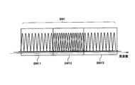
- FIG. 2 is a diagram illustrating an arrangement example of subcarriers in a frequency band transmitted by the wireless communication system 100 according to the first embodiment of the present invention.
- FIG. 3 is a diagram illustrating an example of subcarrier arrangement when the subcarrier interval according to the first embodiment of the present invention is 2 ⁇ ⁇ f.
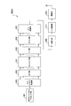
- FIG. 4 is a functional block configuration diagram of the wireless communication apparatus 300 according to the first embodiment of the present invention.
- FIG. 5 is a diagram illustrating simulation results of subcarrier states in the frequency band according to the first embodiment of the present invention.
- FIG. 6 is a diagram illustrating an arrangement example of the subcarriers S11 in the band BW1 that can be used in the wireless communication system 100 according to the second embodiment of the present invention.
- FIG. 7 is a diagram illustrating an example of the subcarrier S11 in the band BW1 and unnecessary waves radiated to the band BW2 according to the second embodiment of the present invention.
- FIG. 8 is a diagram illustrating an arrangement example of subcarriers when the transmission frame F according to the third embodiment of the present invention is divided into time domains.
- FIG. 9 is a diagram showing an example of subcarrier arrangement when the band BW1 according to the fourth embodiment of the present invention is divided into subbands BW11 to BW13.
- FIG. 10 is a diagram illustrating an arrangement example of subcarriers allocated to each user according to the fifth embodiment of the present invention.
- FIG. 11 is a functional block configuration diagram of a wireless communication apparatus 300A according to the sixth embodiment of the present invention.
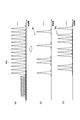
- FIG. 12 is a diagram illustrating an example of subcarrier allocation when clipping noise is superimposed on subcarriers according to the sixth embodiment of the present invention.
- FIG. 1 is an overall schematic configuration diagram of a radio communication system 1 according to the present embodiment. As shown in FIG. 1, the wireless communication system 1 includes a wireless communication system 100 and a wireless communication system 200.
- the wireless communication system 100 includes wireless base stations 110A and 110B and wireless communication terminals 160A and 160B.
- the wireless communication terminals 160A and 160B are portable wireless communication terminals.
- the wireless communication system 100 is a mobile phone system and constitutes a first wireless communication system.
- the wireless communication system 200 includes a transmission station 210 and reception devices 220A and 220B.
- Receiving devices 220A and 220B are receiving devices that are installed at predetermined locations and receive a radio signal RS transmitted from transmitting station 210.
- the wireless communication system 200 is a broadcasting system and constitutes a second wireless communication system.
- the radio base stations 110A and 110B transmit the radio signal RS to the radio communication terminals 160A and 160B.
- the radio base station 110A forms a cover area A1.
- the radio base station 110B forms a cover area A2. That is, the radio communication system 100 is a multi-cell type having a plurality of cells (radio base stations).
- orthogonal frequency division multiplexing In the radio communication system 100 and the radio communication system 200, orthogonal frequency division multiplexing (OFDM) is used.
- OFDM orthogonal frequency division multiplexing
- the radio communication system 100 and the radio communication system 200 are connected via the communication network 10.
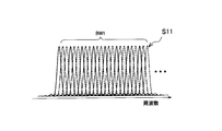
- FIG. 2 shows an example of subcarrier arrangement in a frequency band transmitted by the wireless communication system 100.
- the radio communication system 100 transmits and receives a radio signal RS using a plurality of subcarriers S11 (first subcarriers) having a predetermined frequency interval in the band BW1 (predetermined frequency band).
- the radio communication system 200 transmits and receives a radio signal RS using a plurality of subcarriers S21 (second subcarriers) in a band BW2 (adjacent frequency band) adjacent to the band BW1.
- a time signal specifically, an IFFT unit 305 (FIG. 4) is selected depending on the combination of symbols SY (not shown in FIG. 2, see FIG. 4) to be transmitted.
- a large peak component can occur in the output signal of (see).
- the peak component When the peak component is input by a non-linear element such as a power amplifier constituting the radio unit 313 (see FIG. 4), it causes signal distortion (non-linear distortion). As a result, the amount of out-of-band radiation to the band BW2 adjacent to the band BW1 is increased. As shown in FIG. 2, when all the subcarriers S11 are used, unnecessary waves that are generated outside the band BW1, that is, in the band BW2, are also generated at the frequency interval ( ⁇ f) of all the subcarriers S11.
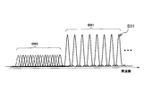
- subcarrier S11 is used at intervals of two subcarriers.
- an unnecessary wave generated on the band BW2 when a signal having two subcarrier intervals passes through a nonlinear element operating in a saturated state is also generated at 2 ⁇ ⁇ f intervals.
- FIG. 3 shows an example of subcarrier arrangement when the subcarrier interval is 2 ⁇ ⁇ f.
- the frequency of the unwanted wave (subcarrier S11) generated from the wireless communication system 100 is f + 2n ⁇ ⁇ f
- the wireless communication system 200 using the band BW2 uses the subcarrier S21 that is f + (2n + 1) ⁇ ⁇ f.
- f is a reference frequency
- ⁇ f is a subcarrier interval
- n corresponds to a subcarrier in each band (band BW1 and band BW2)
- f + 2n ⁇ ⁇ f and f + (2n + 1) ⁇ ⁇ f are the frequencies concerned It is an integer in a range within the bands (band BW1 and band BW2).
- the number of the subcarrier to be used may be fixedly set based on the result of adjustment in the radio communication system 100 and the radio communication system 200. Further, subcarriers usable in the radio communication terminals 160A and 160B constituting the radio communication system 100 may be determined, and the determined subcarrier numbers may be notified to the radio communication system 200. Furthermore, the radio communication system 200 (reception devices 220A and 220B) may transmit the radio signal RS using the notified set of subcarriers (or a part thereof).
- the same subcarrier interval ( ⁇ f) is used in the wireless communication system 100 and the wireless communication system 200.
- the wireless communication system 200 may execute single-carrier communication using a band corresponding to one subcarrier.
- the transmission timing of the symbol SY is synchronized in the radio communication system 100 and the radio communication system 200.
- FIG. 4 is a functional block configuration diagram of the wireless communication apparatus 300.
- the wireless communication device 300 has a function of transmitting a wireless signal RS.
- the wireless communication apparatus 300 includes an encoding / symbol mapping unit 301, a subcarrier processing unit 303, an IFFT unit 305, a P / S conversion unit 307, a GI addition unit 309, a D / A conversion unit 311, and a wireless unit. 313 and a network connection unit 315.
- the encoding / symbol mapping unit 301 performs encoding using an error correction code on the transmitted transmission bit string. Also, the encoding / symbol mapping unit 301 executes mapping to a symbol SY associated with a plurality of bits (for example, 0001).
- the subcarrier processing unit 303 assigns subcarriers to the symbols SY output from the encoding / symbol mapping unit 301. In particular, in the present embodiment, the subcarrier processing unit 303 selects the subcarrier S21 to be used according to the status of the subcarrier S11 used in the radio communication system 100.
- subcarrier processing section 303 constitutes a subcarrier selection section.
- the subcarrier processing unit 303 selects a subcarrier S21 located between the plurality of subcarriers S11 radiated to the band BW2. In the present embodiment, the subcarrier processing unit 303 selects a subcarrier S21 that satisfies f + (NM + m) ⁇ ⁇ f.
- M is an integer in a range where f + (NM + n) ⁇ ⁇ f, which will be described later, falls within the band BW1.
- M is a positive integer other than n and less than N.
- IFFT section 305 performs an inverse Fourier transform of subcarrier S21 output from subcarrier processing section 303, and generates a time signal corresponding to the output subcarrier S21.
- the P / S conversion unit 307 performs parallel-serial conversion of the time signal output from the IFFT unit 305.
- the GI addition unit 309 adds a guard interval, specifically, a part of the time signal to the time signal output from the P / S conversion unit 307.
- the D / A conversion unit 311 performs digital / analog conversion of the time signal in which the guard interval is inserted.
- the wireless unit 313 performs frequency conversion and power amplification of the signal output from the D / A conversion unit 311.
- the radio unit 313 transmits a radio signal RS generated by performing frequency conversion and power amplification from the antenna.
- the radio unit 313 transmits a radio signal RS using the subcarrier S21 selected by the subcarrier processing unit 303.
- a plurality of subcarriers S21 are transmitted in parallel, and each symbol SY is transmitted by one of the subcarriers S21.
- the radio unit 313 can transmit a radio signal RS using the set of subcarriers S21.
- the network connection unit 315 provides a communication interface for connecting to the communication network 10 (see FIG. 1).
- the network connection unit 315 is connected to the subcarrier processing unit 303 and transmits / receives information indicating the status of subcarriers used in the radio communication system 100 and the radio communication system 200.
- the subcarrier S11 satisfies f + (NM + n) ⁇ ⁇ f.
- f is the reference frequency in the band BW1.
- N and n are predetermined natural numbers.
- M is an integer in a range where f + (NM + n) ⁇ ⁇ f falls within the band BW1.
- subcarrier processing section 303 constitutes a used subcarrier determination section.
- the subcarrier processing unit 303 determines N based on the operation status of the wireless communication system 100 acquired by the network connection unit 315. Further, the subcarrier processing unit 303 can determine N and n based on the bandwidth of the band BW1 used in the wireless communication system 100.
- the method of determining the set of subcarriers S11 used in the radio communication system 100 according to the operation status of the radio communication system 200 has been described, but in the radio communication system 100, the operation status of the radio communication system 200 is changed. Regardless, based on a predetermined condition, for example, “select a set of N and m for which the resource usage rate of each radio base station is X% or less”, according to the traffic situation in the radio communication system 100 N and m may be determined. In addition, the radio communication system 200 may select a set of subcarriers S21 to be used according to the usage status of adjacent subcarriers S11.
- the network connection unit 315 acquires the operating status of the wireless communication system 200. Specifically, the network connection unit 315 acquires information indicating the usage status of the subcarrier S21 from the transmission station 210 connected via the communication network 10. The network connection unit 315 notifies the subcarrier processing unit 303 of the acquired information. When the wireless communication device 300 is mounted on the wireless base stations 110A and 110B, the network connection unit 315 constitutes a status acquisition unit.
- the network connection unit 315 can also acquire information indicating a propagation loss between the transmission device and the reception device included in the wireless communication system 200, that is, the transmission station 210 and the reception devices 220A and 220B.
- the band Depending on the state of the radio communication system 200 using BW2, the radio base stations 110A and 110B may control the amount of unnecessary waves transmitted out of the band.
- the radio base stations 110A and 110B when the receiving apparatuses 220A and 220B of the radio communication system 200 using the band BW2 are operating, the radio base stations 110A and 110B maintain the interval for two subcarriers, that is, use Subcarrier S11 is used in a state where the number of subcarriers to be reduced is reduced.
- the radio base stations 110A and 110B may use all the subcarriers S11.
- the position information and the operating state of the receiving apparatuses 220A and 220B may be notified from the receiving apparatuses 220A and 220B to the wireless communication system 100, for example.
- the receiving apparatuses 220A and 220B are not in an operating state, and are the amount of interference caused by the radio signal RS transmitted from the transmitting station 210 and the estimated propagation loss or interference power between the transmitting station 210 and the receiving apparatuses 220A and 220B.
- the necessary reduction amount may be notified to the wireless communication system 100.
- the estimated propagation loss may include the effects of the transmission antenna gain and the reception antenna gain, and the allowable interference level set according to the reception level of the desired wave in the receiving apparatuses 220A and 220B is notified together. May be.
- the radio base stations 110A and 110B determine N, m, and transmission power based on the notified information so that the influence on the receiving apparatuses 220A and 220B is below an allowable level. May be.
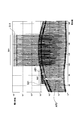
- FIG. 5 shows a simulation result of the state of subcarriers in the frequency band.
- the computer simulation was performed under the following conditions.
- the unnecessary wave level is reduced at the position of the subcarrier used by the radio communication system 200 in the band BW2.
- AR2 in the figure indicates the SIR when the subcarrier S11 and the subcarrier S21 are used by the method described above. That is, according to the present embodiment, even when a radio signal RS having a high power density is received from the radio communication system 100 in the band BW2, the radio communication system 200 reduces interference due to the subcarrier S11 and achieves good reception quality. Can be secured.
- a feature of the subcarrier allocation method according to the present embodiment is that it is effective not only for transmission spurious generated on the transmission side but also for reception intermodulation generated on the reception side.
- the radio communication system 100 and the radio communication system 200 can be avoided without performing complicated processing on the side.
- the radio base stations 110A and 110B use different subcarriers in the same frequency band, thereby reducing inter-cell interference and increasing overall. Wireless resources can be used efficiently.
- the problem to be solved in the present embodiment is likely to occur when the receiver is located at a position close to the radio base station 110A like the receiving device 220A.
- the radio communication system 100 is deployed as a multi-cell type, in general, a plurality of radio base stations are not installed at close positions.
- the reception level of the radio signal RS transmitted from 110B is relatively small. For this reason, unnecessary waves generated by reception intermodulation are also reduced, and it is difficult to be a cause of occurrence of reception intermodulation that hinders communication.
- the reception level of the radio signal RS from any of the radio base stations 110A and 110B is not as great as the receiving device 220A. it is conceivable that. Therefore, according to the present embodiment, it is considered that unnecessary waves generated by reception intermodulation can be effectively suppressed.
- a subcarrier S11 that satisfies f + (NM + n) ⁇ ⁇ f is selected.
- subcarrier S21 that satisfies f + (NM + m) ⁇ ⁇ f is selected.
- m is a positive integer other than n and less than N.
- the wireless communication system 200 selects a set of subcarriers S21 that do not affect the wireless communication system 100 in accordance with the “usage in the wireless communication system 200” and “the influence of the wireless communication system 100 on the wireless communication system 200”. You may judge.
- the radio communication system 100 and the band BW2 are used. Interference with the wireless communication system 200 can be reduced more effectively.
- the transmission timing of the symbol SY is synchronized in the radio communication system 100 and the radio communication system 200. For this reason, the out-of-band radiation amount resulting from the discontinuity of the symbol SY can be suppressed. If the symbol SY operates in the wireless communication system 100 and the wireless communication system 200 without being synchronized, the out-of-band due to distortion of the nonlinear element is more than the out-of-band radiation amount due to the discontinuity of the symbol SY.
- the subcarrier allocation method described above is effective only in a situation where the amount of radiation is large.
- the radio communication system 100 (subcarrier processing unit 303) determines N based on the operation status of the radio communication system 200 acquired via the communication network 10. For this reason, the radio
- FIG. 6 shows an arrangement example of the subcarriers S11 in the band BW1 that can be used in the wireless communication system 100.
- N 3
- radio communication system 100 uses only subcarrier S11 indicated by the solid line among subcarriers S11 shown in FIG.
- FIG. 7 shows an example of the subcarrier S11 in the band BW1 and unnecessary waves radiated to the band BW2.
- N 3
- unnecessary waves are generated at intervals of 3 ⁇ ⁇ f outside the band BW1, specifically, in the band BW2.
- the wireless communication system 200 using the band BW2 uses a subcarrier arrangement pattern indicated by a dotted line or a one-dot chain line.
- the radio communication system 200 may use both subcarrier arrangement patterns indicated by a dotted line or a one-dot chain line.
- the above-described subcarrier intervals are unified between adjacent radio base stations and adjacent to each other. It is preferable to use a subcarrier arrangement pattern different from that of the radio base station. By using such a subcarrier arrangement pattern, subcarriers that are not used at all in a specific area are generated, or by using the same subcarriers as those used by adjacent radio base stations, It is possible to prevent the efficient use of resources from being hindered.
- the interval between the subcarriers S11 set in the wireless communication system 100 may be shared via the communication network 10.
- the radio communication terminals 160A and 160B can measure the subcarrier S11 used in the radio communication system 100 and notify the measurement results to the radio base stations 110A and 110B.
- the radio communication apparatus 300 may include a reception processing unit 321 (see FIG. 1) that receives the measurement results notified from the radio base stations 110A and 110B.
- radio base stations 110A and 110B may not transmit radio signal RS.
- FIG. 8 shows an example of subcarrier arrangement when the transmission frame F is divided into time domains.
- the transmission frame F transmitted in the radio communication system 200 is divided into a plurality of time regions along the time axis, specifically, time zones TS1 and TS2.
- the radio communication system 200 can use subcarriers (subcarriers indicated by dotted lines in FIG. 8) that do not overlap with unnecessary waves due to out-of-band radiation from the radio communication system 100 in the time zone TS1. That is, in the wireless communication system 100 and the wireless communication system 200, the above-described N (subcarrier interval) is different in each time zone.
- the radio communication system 100 transmits all subcarriers in the time zone TS2. For this reason, in the band used by the wireless communication system 200, there is an unnecessary wave due to out-of-band radiation from the wireless communication system 100. That is, the receiving devices 220A and 220B may not normally receive the radio signal RS transmitted by the transmitting station 210.
- the wireless communication system 200 is not a broadcasting system but a communication system that performs communication on a one-to-one basis, such as a wireless LAN system
- a receiving apparatus that receives a large amount of interference from the wireless communication system 100 is indicated by a dotted line in FIG. Only the subcarriers shown in FIG.
- radio communication system 200 is not a broadcast system but a mobile phone system
- a subcarrier indicated by a dotted line in FIG. 8 may be assigned a notification signal or a receiving device that greatly receives interference from radio communication system 100. Good.
- the length of the time zone is determined based on, for example, (i) a pre-fixed value, (ii) an operation status of the radio communication system 200, or (iii) an operation status of the radio communication system 100. Any of the determination methods can be used.
- the radio communication system 200 When determining the length of the time zone based on the operation status of the radio communication system 200, the radio communication system 200 notifies the radio communication system 100 of the operation status.
- the combination of the length of the time zone and the subcarrier arrangement pattern may be changed based on the operation status described above.
- the frequency band that can be used in the wireless communication system 1 is divided into a plurality of continuous bands (subbands). Subcarrier allocation as described above is performed in a specific subband.
- FIG. 9 shows an example of subcarrier arrangement when the band BW1 is divided into subbands BW11 to BW13.
- the subbands located outside that is, the subband BW11 and the subband BW13 only have the intervals corresponding to a plurality of subcarriers (every N subcarriers). ) Is ensured to allocate subcarriers.
- the subband BW12 that is not directly adjacent to the frequency band used by another wireless communication system, it is necessary to use all subcarriers or a specific subcarrier in a pseudo-random manner without securing an interval for a plurality of subcarriers. it can.
- the wireless communication system 200 and the wireless communication system 100 use OFDM. For this reason, in the case of a mobile communication system such as the wireless communication system 100, in the downlink direction, when a signal is transmitted to a plurality of users (wireless communication terminals) using the same symbol SY, A signal may be transmitted using the same symbol SY.
- FIGS. 10A to 10C show examples of arrangement of subcarriers assigned to each user.
- the user 1 is assigned a subcarrier based on the subcarrier pattern P1 (see FIG. 10B).
- a subcarrier based on the subcarrier pattern P2 is assigned to the user 2 (see FIG. 10C).
- subcarrier patterns P1 and P2 can be determined based on, for example, pseudorandomly selected subcarriers or a predetermined number of consecutive subcarriers.
- clipping and filtering is known as a method for reducing the level of a peak portion generated in a transmission radio signal.
- clipping noise is generated by clipping the peak portion of the OFDM signal.
- the following method is known as a clipping noise control method in the frequency domain.
- FIG. 11 is a functional block configuration diagram of the wireless communication device 300A according to the present embodiment. As illustrated in FIG. 11, the wireless communication device 300A includes a clipping unit 331, an FFT unit 333, and a filter unit 335 as compared to the wireless communication device 300 described above.
- the clipping unit 331 executes a clipping process for the OFDM signal output from the IFFT unit 305. Specifically, the clipping unit 331 performs a known clipping processing method (for example, “Effects clipping and filtering on the performance of OFDM”, IEEE Commun. Lett., Vol.2, No.5, pp. 131-133). , May 1998), the clipping of the peak portion of the OFDM signal output from the IFFT section 305 is executed.
- a known clipping processing method for example, “Effects clipping and filtering on the performance of OFDM”, IEEE Commun. Lett., Vol.2, No.5, pp. 131-133). , May 1998)
- the FFT unit 333 performs a Fourier transform of the signal output from the clipping unit 331.
- the filter unit 335 performs filtering on clipping noise included in the signal output from the FFT unit 333.
- subcarriers that are not used in the frequency band and on which clipping noise is superimposed are limited to subcarriers that satisfy the following conditions.
- f + (NM + n) ⁇ ⁇ f N, n is a predetermined natural number M limited to subcarriers that satisfy an integer in a range where f + (NM + n) ⁇ ⁇ f is within the band of the wireless communication system 100.
- FIG. 12 shows an example of subcarrier allocation when clipping noise is superimposed on subcarriers.
- radio communication system 100 uses subcarriers every two subcarriers, when using subcarriers indicated by solid lines, clipping noise is superimposed only on subcarriers indicated by alternate long and short dash lines. Can be controlled. For this reason, it is possible to prevent a large interference from being applied to the subcarrier S21 used by the radio communication system 200.
- the subcarriers used by the radio communication system 200 in the band BW2 adjacent to the band BW1 depend on the dynamic range of the nonlinear element and the size of the input peak portion. The level of unwanted waves with respect to increases.
- an allowable clipping noise level is estimated in advance, and clipping noise is allowed up to that level. Good.
- the wireless communication system 100 and the wireless communication system 200 do not necessarily use OFDM, and use a plurality of subcarriers. It only has to be.
- the case where another radio communication system uses an adjacent frequency band has been described as an example.
- Parameters such as a subcarrier interval to be used and transmission power may be determined in consideration of a wireless communication system that uses a band (for example, a frequency band adjacent to the adjacent frequency band).
- the above-described subcarrier allocation method can be applied regardless of whether the adjacent frequency band is used by different operators or the same operator. Further, it may be a frequency band in which a license is exclusively granted to a specific operator, or a frequency band that does not require a license as used in a short-range wireless communication system such as a wireless LAN system. Also good.
- the power control of the radio signal RS to be transmitted and the adjustment of the guard band may be used in combination.
- the number of time domain segments (time zones TS) along the time axis is three or more.
- the usage rate in some of these sections may be zero.
- a notification signal such as a control signal may be transmitted during the time when the usage rate is zero.
- the wireless communication system 100 is a mobile phone system and the wireless communication system 200 is a broadcast system.
- the wireless communication system 100 and the wireless communication system 200 are not limited to such a system. It does not have to be.
- the wireless communication system 200 may be a satellite communication system or a wireless LAN system.
- the wireless communication system 100 has been described as a multi-cell type having a plurality of cells, but the wireless communication system 100 may be a single-cell type.
- the radio communication system according to the present invention can effectively reduce interference with an adjacent radio communication system using adjacent frequency bands when a multicarrier scheme is used. This is useful in wireless communication such as body communication.
Abstract
A second radio communication system selects a subcarrier S21 to be used in accordance with a subcarrier S11. The second radio communication system transmits a radio signal using the selected subcarrier S21. When selecting a subcarrier S21, the subcarrier S21 positioned between a plurality of subcarriers S11 radiated in a band BW2 is selected.
Description
本発明は、所定の周波数間隔を有する複数のサブキャリアを用いた無線信号を送受信する第1無線通信システムと、隣接周波数帯域において、複数のサブキャリアを用いた無線信号を送受信する第2無線通信システムとを含む無線通信システムに関する。
The present invention provides a first wireless communication system that transmits and receives wireless signals using a plurality of subcarriers having a predetermined frequency interval, and a second wireless communication that transmits and receives wireless signals using a plurality of subcarriers in an adjacent frequency band. And a wireless communication system including the system.
従来、無線通信システムでは、隣接する周波数帯域を使用する隣接無線通信システムとの干渉を防止するため、様々な対策がなされている。
Conventionally, in wireless communication systems, various measures have been taken to prevent interference with adjacent wireless communication systems that use adjacent frequency bands.
一般には、各無線通信システムにおいて送信される無線信号の周波数特性が、送信電力のスペクトラムマスクとして規定される。各無線通信システムは、スペクトラムマスクを超えない範囲で帯域外輻射量に抑えることによって、システム間干渉を回避する。しかしながら、当該方法は、主に送信側における相互変調歪の対策である。つまり、受信側における相互変調歪による影響を十分に抑制することが難しい。また、過度に厳しいスペクトラムマスクを規定することは、各無線通信システムを構成する装置のコストやサイズの増大に繋がるため、好ましくない。
Generally, the frequency characteristics of radio signals transmitted in each radio communication system are defined as a spectrum mask of transmission power. Each wireless communication system avoids inter-system interference by suppressing the amount of out-of-band radiation within a range not exceeding the spectrum mask. However, this method is mainly a measure against intermodulation distortion on the transmission side. That is, it is difficult to sufficiently suppress the influence of intermodulation distortion on the receiving side. Also, it is not preferable to specify an excessively strict spectrum mask because it leads to an increase in cost and size of devices constituting each wireless communication system.
また、動的にシステム間干渉を制御する方法も知られている(例えば、特許文献1)。当該方法では、データ伝送に用いられる主波が他の無線通信システムに与える影響が考慮される。なお、当該方法では、スプリアスが他の無線通信システムに与える影響については言及されていない。
Also, a method for dynamically controlling interference between systems is known (for example, Patent Document 1). In this method, the influence of the main wave used for data transmission on other wireless communication systems is considered. Note that this method does not mention the effect of spurious on other wireless communication systems.
ところで、OFDMなど、複数のサブキャリアを用いて複数の信号が並列に伝送されるマルチキャリア方式の無線通信システムでは、送信される信号の組合せによって大きなピーク成分が送信信号中に発生する場合がある。このため、受信装置の低雑音増幅器(LNA)やミキサーなどを構成する非線形素子の飽和領域における動作に起因する他の無線通信システムとの干渉(スプリアス)が問題となり易い。
By the way, in a multi-carrier wireless communication system such as OFDM in which a plurality of signals are transmitted in parallel using a plurality of subcarriers, a large peak component may be generated in the transmission signal depending on the combination of transmitted signals. . For this reason, interference (spurious) with other radio communication systems due to the operation in the saturation region of the nonlinear elements constituting the low noise amplifier (LNA), mixer, etc. of the receiving apparatus tends to be a problem.
特に、高速な通信速度を確保するため、連続した広い周波数帯域ではなく、不連続な複数の周波数帯域をまとめて利用する場合、他の無線通信システムとの干渉は深刻な問題となる。
Especially, in order to secure a high communication speed, when using a plurality of discontinuous frequency bands together instead of a continuous wide frequency band, interference with other radio communication systems becomes a serious problem.
そこで、本発明は、このような状況に鑑みてなされたものであり、マルチキャリア方式が用いられる場合において、隣接する周波数帯域を使用する隣接無線通信システムとの干渉をより効果的に低減することができる無線通信システムを提供することを目的とする。
Therefore, the present invention has been made in view of such a situation, and more effectively reduces interference with an adjacent wireless communication system using adjacent frequency bands when a multicarrier scheme is used. An object of the present invention is to provide a wireless communication system capable of
上述した問題を解決するため、本発明は、次のような特徴を有している。まず、本発明の第1の特徴は、所定の周波数帯域(帯域BW1)において、所定の周波数間隔を有する複数の第1サブキャリア(サブキャリアS11)を用いた無線信号(無線信号RS)を送受信する第1無線通信システム(無線通信システム100)と、前記所定の周波数帯域に隣接する隣接周波数帯域(帯域BW2)において、複数の第2サブキャリア(サブキャリアS21)を用いた無線信号(無線信号RS)を送受信する第2無線通信システム(無線通信システム200)とを含む無線通信システム(無線通信システム1)であって、前記第2無線通信システムは、前記第1サブキャリアの状況に応じて、使用する前記第2サブキャリアを選択するサブキャリア選択部(サブキャリア処理部303)と、前記サブキャリア選択部によって選択された前記第2サブキャリアを用いた無線信号を送信する送信部(無線部313)と備え、前記サブキャリア選択部は、前記隣接周波数帯域に輻射された複数の前記第1サブキャリアの間に位置する前記第2サブキャリアを選択することを要旨とする。
In order to solve the above-described problem, the present invention has the following features. First, the first feature of the present invention is that a radio signal (radio signal RS) using a plurality of first subcarriers (subcarriers S11) having a predetermined frequency interval is transmitted and received in a predetermined frequency band (band BW1). Wireless signals (radio signals) using a plurality of second subcarriers (subcarriers S21) in the first wireless communication system (wireless communication system 100) and the adjacent frequency band (band BW2) adjacent to the predetermined frequency band RS (radio communication system 1) including a second radio communication system (radio communication system 200) that transmits and receives (RS), wherein the second radio communication system depends on the state of the first subcarrier. A subcarrier selection unit (subcarrier processing unit 303) that selects the second subcarrier to be used, and the subcarrier selection unit. And a transmission unit (radio unit 313) for transmitting a radio signal using the second subcarrier selected in the above, wherein the subcarrier selection unit includes a plurality of the first subcarriers radiated to the adjacent frequency band. The gist is to select the second subcarrier located between them.
このような無線通信システムによれば、第2無線通信システムでは、第1無線通信システムが用いる第1サブキャリアの状況に応じて、前記隣接周波数帯域に輻射された複数の第1サブキャリアの間に位置する第2サブキャリアが選択される。
According to such a wireless communication system, in the second wireless communication system, a plurality of first subcarriers radiated to the adjacent frequency band are used depending on the state of the first subcarrier used by the first wireless communication system. The second subcarrier located at is selected.
このため、非線形素子の飽和領域における動作に起因する隣接周波数帯域への無線信号の輻射、つまり、帯域外輻射が発生した場合でも隣接周波数帯域を使用する無線通信システムとの干渉をより効果的に低減することができる。
For this reason, radio signal radiation to the adjacent frequency band due to operation in the saturation region of the nonlinear element, that is, interference with a radio communication system using the adjacent frequency band even when out-of-band radiation occurs more effectively. Can be reduced.
本発明の第2の特徴は、本発明の第1の特徴に係り、前記第1無線通信システムは、f+(NM+n)×Δfを満足し、前記fは、前記所定の周波数帯域における基準周波数、前記Δfは、前記第1サブキャリアの間隔、前記N及び前記nは、所定の自然数、Mは、f+(NM+n)×Δfが前記所定の周波数帯域内となる範囲の整数である前記第1サブキャリアを使用する使用サブキャリア決定部(サブキャリア処理部303)を備え、前記サブキャリア選択部は、f+(NM+m)×Δfを満足し、前記mは、前記n以外であって、前記N未満の正の整数である前記第2サブキャリアを選択することを要旨とする。
A second feature of the present invention relates to the first feature of the present invention, wherein the first wireless communication system satisfies f + (NM + n) × Δf, wherein f is a reference frequency in the predetermined frequency band, Δf is an interval between the first subcarriers, N and n are predetermined natural numbers, and M is an integer in a range where f + (NM + n) × Δf is within the predetermined frequency band. A subcarrier determining unit (subcarrier processing unit 303) that uses a carrier, wherein the subcarrier selecting unit satisfies f + (NM + m) × Δf, and m is other than n and less than N The second subcarrier, which is a positive integer, is selected.
本発明の第3の特徴は、本発明の第2の特徴に係り、前記第1無線通信システム及び前記第2無線通信システムでは、直交周波数分割多重が用いられることを要旨とする。
A third feature of the present invention relates to the second feature of the present invention, and is summarized in that orthogonal frequency division multiplexing is used in the first wireless communication system and the second wireless communication system.
本発明の第4の特徴は、本発明の第3の特徴に係り、前記第1無線通信システム及び前記第2無線通信システムでは、複数のビットが対応付けられたシンボル(シンボルSY)が用いられ、前記シンボルの送信タイミングは、前記第1無線通信システム及び前記第2無線通信システムにおいて同期していることを要旨とする。
A fourth feature of the present invention relates to the third feature of the present invention. In the first wireless communication system and the second wireless communication system, a symbol (symbol SY) associated with a plurality of bits is used. The symbol transmission timing is synchronized in the first wireless communication system and the second wireless communication system.
本発明の第5の特徴は、本発明の第2の特徴に係り、前記Nは、N≧2を満足し、前記サブキャリア選択部は、複数の前記mに対応する前記第2サブキャリアのセットを選択し、前記送信部は、前記サブキャリア選択部によって選択された前記第2サブキャリアのセットを用いた無線信号を送信することを要旨とする。
A fifth feature of the present invention relates to the second feature of the present invention, wherein the N satisfies N ≧ 2, and the subcarrier selection unit includes a plurality of the second subcarriers corresponding to the m. The gist is to select a set, and the transmission unit transmits a radio signal using the second subcarrier set selected by the subcarrier selection unit.
本発明の第6の特徴は、本発明の第2の特徴に係り、前記第1無線通信システムにおいて送信される送信フレーム(送信フレームF)は、時間軸に沿った複数の時間領域(時間帯TS1,TS2)に区分され、前記第1無線通信システム及び前記第2無線通信システムにおいて、前記Nは、それぞれの前記時間領域において異なることを要旨とする。
A sixth feature of the present invention relates to the second feature of the present invention, wherein a transmission frame (transmission frame F) transmitted in the first wireless communication system has a plurality of time domains (time zones) along the time axis. TS1, TS2), and in the first radio communication system and the second radio communication system, the N is different in each time domain.
本発明の第7の特徴は、本発明の第2の特徴に係り、前記第1無線通信システムは、前記第2無線通信システムの稼働状況を取得する状況取得部(例えば、ネットワーク接続部315)を備え、前記使用サブキャリア決定部は、前記状況取得部によって取得された前記稼働状況に基づいて前記Nを決定することを要旨とする。
A seventh feature of the present invention relates to the second feature of the present invention, wherein the first wireless communication system acquires a status acquisition unit (for example, a network connection unit 315) that acquires an operating status of the second wireless communication system. And the used subcarrier determining unit determines N based on the operating status acquired by the status acquiring unit.
本発明の第8の特徴は、本発明の第7の特徴に係り、前記状況取得部は、前記第2無線通信システムに含まれる送信装置と受信装置との間における伝搬損失を含むことを要旨とする。
An eighth feature of the present invention relates to the seventh feature of the present invention, wherein the status acquisition unit includes a propagation loss between a transmission device and a reception device included in the second wireless communication system. And
本発明の第9の特徴は、本発明の第2の特徴に係り、前記使用サブキャリア決定部は、前記第1無線通信システムにおいて使用される前記所定の周波数帯域の帯域幅に基づいて前記N及び前記nを決定することを要旨とする。
A ninth feature of the present invention relates to the second feature of the present invention, wherein the used subcarrier determining unit determines the N based on a bandwidth of the predetermined frequency band used in the first wireless communication system. And determining n.
本発明の特徴によれば、マルチキャリア方式が用いられる場合において、隣接する周波数帯域を使用する隣接無線通信システムとの干渉をより効果的に低減することができる無線通信システムを提供することができる。
According to the characteristics of the present invention, it is possible to provide a radio communication system that can more effectively reduce interference with an adjacent radio communication system that uses adjacent frequency bands when a multicarrier scheme is used. .
次に、本発明の実施形態について説明する。具体的には、第1実施形態~第6実施形態について説明する。
Next, an embodiment of the present invention will be described. Specifically, the first to sixth embodiments will be described.
なお、以下の図面の記載において、同一または類似の部分には、同一または類似の符号を付している。ただし、図面は模式的なものであり、各寸法の比率などは現実のものとは異なることに留意すべきである。
In the description of the drawings below, the same or similar parts are denoted by the same or similar reference numerals. However, it should be noted that the drawings are schematic and ratios of dimensions and the like are different from actual ones.
したがって、具体的な寸法などは以下の説明を参酌して判断すべきものである。また、図面相互間においても互いの寸法の関係や比率が異なる部分が含まれていることは勿論である。
Therefore, specific dimensions should be determined in consideration of the following explanation. Moreover, it is a matter of course that portions having different dimensional relationships and ratios are included between the drawings.
[第1実施形態]
まず、本発明の第1実施形態について説明する。具体的には、(1)無線通信システムの全体概略構成、(2)無線通信システムの動作概略、(3)無線通信システムの機能ブロック構成、(4)変形例、及び(5)作用・効果について説明する。 [First Embodiment]
First, a first embodiment of the present invention will be described. Specifically, (1) the overall schematic configuration of the radio communication system, (2) the outline of the operation of the radio communication system, (3) the functional block configuration of the radio communication system, (4) the modification, and (5) the operation and effect Will be described.
(1)無線通信システムの全体概略構成
図1は、本実施形態に係る無線通信システム1の全体概略構成図である。図1に示すように、無線通信システム1は、無線通信システム100と、無線通信システム200とを含む。 (1) Overall Schematic Configuration of Radio Communication System FIG. 1 is an overall schematic configuration diagram of a radio communication system 1 according to the present embodiment. As shown in FIG. 1, the wireless communication system 1 includes awireless communication system 100 and a wireless communication system 200.
図1は、本実施形態に係る無線通信システム1の全体概略構成図である。図1に示すように、無線通信システム1は、無線通信システム100と、無線通信システム200とを含む。 (1) Overall Schematic Configuration of Radio Communication System FIG. 1 is an overall schematic configuration diagram of a radio communication system 1 according to the present embodiment. As shown in FIG. 1, the wireless communication system 1 includes a
無線通信システム100は、無線基地局110A,110B及び無線通信端末160A,160Bを含む。無線通信端末160A,160Bは、携帯型の無線通信端末である。本実施形態において、無線通信システム100は、携帯電話システムであり、第1無線通信システムを構成する。
The wireless communication system 100 includes wireless base stations 110A and 110B and wireless communication terminals 160A and 160B. The wireless communication terminals 160A and 160B are portable wireless communication terminals. In the present embodiment, the wireless communication system 100 is a mobile phone system and constitutes a first wireless communication system.
無線通信システム200は、送信局210及び受信装置220A,220Bを含む。受信装置220A,220Bは、所定の場所に設置され、送信局210から送信された無線信号RSを受信する受信装置である。本実施形態において、無線通信システム200は、放送システムであり、第2無線通信システムを構成する。
The wireless communication system 200 includes a transmission station 210 and reception devices 220A and 220B. Receiving devices 220A and 220B are receiving devices that are installed at predetermined locations and receive a radio signal RS transmitted from transmitting station 210. In the present embodiment, the wireless communication system 200 is a broadcasting system and constitutes a second wireless communication system.
無線基地局110A,110Bは、無線通信端末160A,160Bに向けて無線信号RSを送信する。無線基地局110Aは、カバーエリアA1を形成する。また、無線基地局110Bは、カバーエリアA2を形成する。つまり、無線通信システム100は、複数のセル(無線基地局)を有するマルチセル型である。
The radio base stations 110A and 110B transmit the radio signal RS to the radio communication terminals 160A and 160B. The radio base station 110A forms a cover area A1. Further, the radio base station 110B forms a cover area A2. That is, the radio communication system 100 is a multi-cell type having a plurality of cells (radio base stations).
無線通信システム100及び無線通信システム200では、直交周波数分割多重(OFDM)が用いられる。また、無線通信システム100と無線通信システム200とは、通信ネットワーク10を介して接続される。
In the radio communication system 100 and the radio communication system 200, orthogonal frequency division multiplexing (OFDM) is used. The radio communication system 100 and the radio communication system 200 are connected via the communication network 10.
(2)無線通信システムの動作概略
次に、無線通信システム1の動作概略について説明する。図2は、無線通信システム100が送信する周波数帯域におけるサブキャリアの配置例を示す。 (2) Outline of Operation of Radio Communication System Next, an outline of operation of the radio communication system 1 will be described. FIG. 2 shows an example of subcarrier arrangement in a frequency band transmitted by thewireless communication system 100.
次に、無線通信システム1の動作概略について説明する。図2は、無線通信システム100が送信する周波数帯域におけるサブキャリアの配置例を示す。 (2) Outline of Operation of Radio Communication System Next, an outline of operation of the radio communication system 1 will be described. FIG. 2 shows an example of subcarrier arrangement in a frequency band transmitted by the
無線通信システム100は、帯域BW1(所定の周波数帯域)において、所定の周波数間隔を有する複数のサブキャリアS11(第1サブキャリア)を用いた無線信号RSを送受信する。
The radio communication system 100 transmits and receives a radio signal RS using a plurality of subcarriers S11 (first subcarriers) having a predetermined frequency interval in the band BW1 (predetermined frequency band).
また、無線通信システム200は、帯域BW1に隣接する帯域BW2(隣接周波数帯域)において、複数のサブキャリアS21(第2サブキャリア)を用いた無線信号RSを送受信する。
Further, the radio communication system 200 transmits and receives a radio signal RS using a plurality of subcarriers S21 (second subcarriers) in a band BW2 (adjacent frequency band) adjacent to the band BW1.
無線通信システム100及び無線通信システム200ではOFDMが用いられるため、伝送されるシンボルSY(図2において不図示、図4参照)の組合せによって、時間信号、具体的には、IFFT部305(図4参照)の出力信号において、大きなピーク成分が発生し得る。
Since OFDM is used in the radio communication system 100 and the radio communication system 200, a time signal, specifically, an IFFT unit 305 (FIG. 4) is selected depending on the combination of symbols SY (not shown in FIG. 2, see FIG. 4) to be transmitted. A large peak component can occur in the output signal of (see).
当該ピーク成分が、無線部313(図4参照)を構成する電力増幅器などの非線形素子により入力されると、信号の歪(非線形歪)の原因となる。この結果、帯域BW1に隣接する帯域BW2への帯域外輻射量を増加させる。また、図2に示すように、全てのサブキャリアS11を使用すると、帯域BW1の帯域外、つまり、帯域BW2において発生する不要波も、全てのサブキャリアS11の周波数間隔(Δf)で発生する。
When the peak component is input by a non-linear element such as a power amplifier constituting the radio unit 313 (see FIG. 4), it causes signal distortion (non-linear distortion). As a result, the amount of out-of-band radiation to the band BW2 adjacent to the band BW1 is increased. As shown in FIG. 2, when all the subcarriers S11 are used, unnecessary waves that are generated outside the band BW1, that is, in the band BW2, are also generated at the frequency interval (Δf) of all the subcarriers S11.
本実施形態では、サブキャリアS11を2サブキャリア間隔で使用する。この場合、2サブキャリア間隔を有する信号が、飽和状態で動作する非線形素子を通過することによって帯域BW2上に生じる不要波も2×Δf間隔で発生する。
In this embodiment, subcarrier S11 is used at intervals of two subcarriers. In this case, an unnecessary wave generated on the band BW2 when a signal having two subcarrier intervals passes through a nonlinear element operating in a saturated state is also generated at 2 × Δf intervals.
図3は、サブキャリアの間隔を2×Δf間隔とした場合におけるサブキャリアの配置例を示す。無線通信システム100から発生した不要波(サブキャリアS11)の周波数をf+2n×Δfとすると、帯域BW2を使用する無線通信システム200においては、f+(2n+1)×ΔfとなるサブキャリアS21を利用して通信を実行させる。ここで、fは基準となる周波数、Δfはサブキャリア間隔、nはそれぞれの帯域(帯域BW1及び帯域BW2)内のサブキャリアに対応し、f+2n×Δf及びf+(2n+1)×Δfが、当該周波数帯域(帯域BW1及び帯域BW2)内となる範囲の整数である。
FIG. 3 shows an example of subcarrier arrangement when the subcarrier interval is 2 × Δf. Assuming that the frequency of the unwanted wave (subcarrier S11) generated from the wireless communication system 100 is f + 2n × Δf, the wireless communication system 200 using the band BW2 uses the subcarrier S21 that is f + (2n + 1) × Δf. Execute communication. Here, f is a reference frequency, Δf is a subcarrier interval, n corresponds to a subcarrier in each band (band BW1 and band BW2), and f + 2n × Δf and f + (2n + 1) × Δf are the frequencies concerned It is an integer in a range within the bands (band BW1 and band BW2).
なお、使用するサブキャリアの番号は、無線通信システム100と無線通信システム200とにおける調整の結果に基づいて、固定的に設定してもよい。また、無線通信システム100を構成する無線通信端末160A,160Bにおいて使用可能なサブキャリアを判別し、判別したサブキャリアの番号を無線通信システム200に通知してもよい。さらに、無線通信システム200(受信装置220A,220B)は、通知されたサブキャリアのセット(或いはその一部)を用いて無線信号RSを送信してもよい。
Note that the number of the subcarrier to be used may be fixedly set based on the result of adjustment in the radio communication system 100 and the radio communication system 200. Further, subcarriers usable in the radio communication terminals 160A and 160B constituting the radio communication system 100 may be determined, and the determined subcarrier numbers may be notified to the radio communication system 200. Furthermore, the radio communication system 200 ( reception devices 220A and 220B) may transmit the radio signal RS using the notified set of subcarriers (or a part thereof).
本実施形態では、無線通信システム100と無線通信システム200とでは、同一のサブキャリア間隔(Δf)が用いられる。なお、無線通信システム200は、1サブキャリア分に相当する帯域を用いてシングルキャリアによる通信を実行してもよい。
In the present embodiment, the same subcarrier interval (Δf) is used in the wireless communication system 100 and the wireless communication system 200. Note that the wireless communication system 200 may execute single-carrier communication using a band corresponding to one subcarrier.
また、本実施形態では、シンボルSYの送信タイミングは、無線通信システム100及び無線通信システム200において同期している。
In the present embodiment, the transmission timing of the symbol SY is synchronized in the radio communication system 100 and the radio communication system 200.
(3)無線通信システムの機能ブロック構成
次に、無線通信システム1の機能ブロック構成について説明する。具体的には、無線通信システム1を構成する無線基地局110A,210B、或いは無線通信システム200を構成する送信局210に実装される無線通信装置300の機能ブロック構成について説明する。 (3) Functional Block Configuration of Radio Communication System Next, a functional block configuration of the radio communication system 1 will be described. Specifically, the functional block configuration of theradio communication apparatus 300 implemented in the radio base stations 110A and 210B constituting the radio communication system 1 or the transmission station 210 constituting the radio communication system 200 will be described.
次に、無線通信システム1の機能ブロック構成について説明する。具体的には、無線通信システム1を構成する無線基地局110A,210B、或いは無線通信システム200を構成する送信局210に実装される無線通信装置300の機能ブロック構成について説明する。 (3) Functional Block Configuration of Radio Communication System Next, a functional block configuration of the radio communication system 1 will be described. Specifically, the functional block configuration of the
(3.1)送信局210に実装される場合
まず、無線通信装置300が送信局210に実装される場合について説明する。図4は、無線通信装置300の機能ブロック構成図である。無線通信装置300は、無線信号RSを送信する機能を備える。具体的には、無線通信装置300は、符号化・シンボルマッピング部301、サブキャリア処理部303、IFFT部305、P/S変換部307、GI付加部309、D/A変換部311、無線部313及びネットワーク接続部315を備える。 (3.1) When Mounted on TransmittingStation 210 First, a case where the wireless communication apparatus 300 is mounted on the transmitting station 210 will be described. FIG. 4 is a functional block configuration diagram of the wireless communication apparatus 300. The wireless communication device 300 has a function of transmitting a wireless signal RS. Specifically, the wireless communication apparatus 300 includes an encoding / symbol mapping unit 301, a subcarrier processing unit 303, an IFFT unit 305, a P / S conversion unit 307, a GI addition unit 309, a D / A conversion unit 311, and a wireless unit. 313 and a network connection unit 315.
まず、無線通信装置300が送信局210に実装される場合について説明する。図4は、無線通信装置300の機能ブロック構成図である。無線通信装置300は、無線信号RSを送信する機能を備える。具体的には、無線通信装置300は、符号化・シンボルマッピング部301、サブキャリア処理部303、IFFT部305、P/S変換部307、GI付加部309、D/A変換部311、無線部313及びネットワーク接続部315を備える。 (3.1) When Mounted on Transmitting
符号化・シンボルマッピング部301は、伝送される送信ビット列に対して、誤り訂正符号による符号化を実行する。また、符号化・シンボルマッピング部301は、複数のビット(例えば、0001)が対応付けられたシンボルSYへのマッピングなどを実行する。
The encoding / symbol mapping unit 301 performs encoding using an error correction code on the transmitted transmission bit string. Also, the encoding / symbol mapping unit 301 executes mapping to a symbol SY associated with a plurality of bits (for example, 0001).
サブキャリア処理部303は、符号化・シンボルマッピング部301から出力されたシンボルSYにサブキャリアを割り当てる。特に、本実施形態では、サブキャリア処理部303は、無線通信システム100において用いられるサブキャリアS11の状況に応じて、使用するサブキャリアS21を選択する。無線通信装置300が送信局210に実装される場合、サブキャリア処理部303は、サブキャリア選択部を構成する。
The subcarrier processing unit 303 assigns subcarriers to the symbols SY output from the encoding / symbol mapping unit 301. In particular, in the present embodiment, the subcarrier processing unit 303 selects the subcarrier S21 to be used according to the status of the subcarrier S11 used in the radio communication system 100. When radio communication apparatus 300 is installed in transmitting station 210, subcarrier processing section 303 constitutes a subcarrier selection section.
具体的には、サブキャリア処理部303は、帯域BW2に輻射された複数のサブキャリアS11の間に位置するサブキャリアS21を選択する。本実施形態では、サブキャリア処理部303は、f+(NM+m)×Δfを満足するサブキャリアS21を選択する。
Specifically, the subcarrier processing unit 303 selects a subcarrier S21 located between the plurality of subcarriers S11 radiated to the band BW2. In the present embodiment, the subcarrier processing unit 303 selects a subcarrier S21 that satisfies f + (NM + m) × Δf.
なお、Nは、使用されるサブキャリアの間隔を示し、予め規定された自然数(所定の自然数)である。Nは、N≧2を満足する。例えば、N=2であれば、1サブキャリア毎にサブキャリアが使用される。より具体的には、サブキャリア#1,3,5…が使用される。
Note that N represents an interval between subcarriers to be used, and is a pre-defined natural number (predetermined natural number). N satisfies N ≧ 2. For example, if N = 2, a subcarrier is used for each subcarrier. More specifically, subcarriers # 1, 3, 5,... Are used.
Mは、後述するf+(NM+n)×Δfが帯域BW1内となる範囲の整数である。また、mは、n以外であってN未満の正の整数である。
M is an integer in a range where f + (NM + n) × Δf, which will be described later, falls within the band BW1. M is a positive integer other than n and less than N.
また、サブキャリア処理部303は、複数のmに対応するサブキャリアS21のセットを選択することができる。複数のmに対応するサブキャリアS21のセットが選択される場合、Nだけではなく、mも決定する必要がある。例えば、サブキャリア#1,3,5が使用される場合、サブキャリア#0の周波数をfとすると、m=1と決定される。
Also, the subcarrier processing unit 303 can select a set of subcarriers S21 corresponding to a plurality of m. When a set of subcarriers S21 corresponding to a plurality of m is selected, it is necessary to determine not only N but also m. For example, when subcarriers # 1, 3, and 5 are used, m = 1 is determined if the frequency of subcarrier # 0 is f.
IFFT部305は、サブキャリア処理部303から出力されたサブキャリアS21の逆フーリエ変換を実行し、出力されたサブキャリアS21に対応する時間信号を生成する。
IFFT section 305 performs an inverse Fourier transform of subcarrier S21 output from subcarrier processing section 303, and generates a time signal corresponding to the output subcarrier S21.
P/S変換部307は、IFFT部305から出力された時間信号の並直列変換を実行する。
The P / S conversion unit 307 performs parallel-serial conversion of the time signal output from the IFFT unit 305.
GI付加部309は、P/S変換部307から出力された時間信号にガードインターバル、具体的には、当該時間信号の一部を付加する。
The GI addition unit 309 adds a guard interval, specifically, a part of the time signal to the time signal output from the P / S conversion unit 307.
D/A変換部311は、ガードインターバルが挿入された時間信号のディジタル/アナログ変換を実行する。
The D / A conversion unit 311 performs digital / analog conversion of the time signal in which the guard interval is inserted.
無線部313は、D/A変換部311から出力された信号の周波数変換及び電力増幅を実行する。また、無線部313は、周波数変換及び電力増幅を実行することによって生成された無線信号RSをアンテナから送信する。
The wireless unit 313 performs frequency conversion and power amplification of the signal output from the D / A conversion unit 311. In addition, the radio unit 313 transmits a radio signal RS generated by performing frequency conversion and power amplification from the antenna.
すなわち、無線部313は、サブキャリア処理部303によって選択されたサブキャリアS21を用いた無線信号RSを送信する。複数のサブキャリアS21は並列して送信され、各シンボルSYは、何れかのサブキャリアS21によって伝送される。
That is, the radio unit 313 transmits a radio signal RS using the subcarrier S21 selected by the subcarrier processing unit 303. A plurality of subcarriers S21 are transmitted in parallel, and each symbol SY is transmitted by one of the subcarriers S21.
また、無線部313は、サブキャリア処理部303によって複数のmに対応するサブキャリアS21のセットを選択された場合、当該サブキャリアS21のセットを用いた無線信号RSを送信することができる。
Also, when the subcarrier processing unit 303 selects a set of subcarriers S21 corresponding to a plurality of m, the radio unit 313 can transmit a radio signal RS using the set of subcarriers S21.
ネットワーク接続部315は、通信ネットワーク10(図1参照)と接続するための通信インタフェースを提供する。ネットワーク接続部315は、サブキャリア処理部303と接続され、無線通信システム100及び無線通信システム200において使用されているサブキャリアの状況を示す情報などを送受信する。
The network connection unit 315 provides a communication interface for connecting to the communication network 10 (see FIG. 1). The network connection unit 315 is connected to the subcarrier processing unit 303 and transmits / receives information indicating the status of subcarriers used in the radio communication system 100 and the radio communication system 200.
(3.2)無線基地局110A,110Bに実装される場合
無線通信装置300が無線基地局110A,110Bに実装される場合、無線通信装置300は、以下に説明する機能を提供する。なお、以下、上述した無線通信装置300が送信局210に実装される場合と異なる部分について説明する。 (3.2) When Implemented in Radio Base Stations 110A and 110B When the radio communication apparatus 300 is implemented in the radio base stations 110A and 110B, the radio communication apparatus 300 provides the functions described below. Hereinafter, parts different from the case where the above-described wireless communication apparatus 300 is mounted on the transmission station 210 will be described.
無線通信装置300が無線基地局110A,110Bに実装される場合、無線通信装置300は、以下に説明する機能を提供する。なお、以下、上述した無線通信装置300が送信局210に実装される場合と異なる部分について説明する。 (3.2) When Implemented in
本実施形態では、無線基地局110A,110Bが含まれる無線通信システム100では、サブキャリアS11は、f+(NM+n)×Δfを満足する。上述したように、fは、帯域BW1における基準周波数である。N及びnは、所定の自然数である。また、Mは、f+(NM+n)×Δfが帯域BW1内となる範囲の整数である。無線通信装置300が無線基地局110A,110Bに実装される場合、サブキャリア処理部303は、使用サブキャリア決定部を構成する。
In the present embodiment, in the wireless communication system 100 including the wireless base stations 110A and 110B, the subcarrier S11 satisfies f + (NM + n) × Δf. As described above, f is the reference frequency in the band BW1. N and n are predetermined natural numbers. M is an integer in a range where f + (NM + n) × Δf falls within the band BW1. When radio communication apparatus 300 is mounted on radio base stations 110A and 110B, subcarrier processing section 303 constitutes a used subcarrier determination section.
サブキャリア処理部303は、ネットワーク接続部315によって取得された無線通信システム100の稼働状況に基づいてNを決定する。また、サブキャリア処理部303は、無線通信システム100において使用される帯域BW1の帯域幅に基づいてN及びnを決定することができる。
The subcarrier processing unit 303 determines N based on the operation status of the wireless communication system 100 acquired by the network connection unit 315. Further, the subcarrier processing unit 303 can determine N and n based on the bandwidth of the band BW1 used in the wireless communication system 100.
具体的には、無線通信システム200の稼働状況が低い場合、N=3と設定され、無線通信システム100では、1つのmに対するサブキャリアS11のセットが使用される。無線通信システム200の稼動率が上昇するに連れて、「N=2、無線通信システム100では、1つのmに対するサブキャリアS11のセットを使用」から、「N=3、無線通信システム100では、2つのmに対するサブキャリアS11のセットを使用」というように、N及びmが決定される。
Specifically, when the operation status of the radio communication system 200 is low, N = 3 is set, and the radio communication system 100 uses a set of subcarriers S11 for one m. As the operation rate of the wireless communication system 200 increases, “N = 2, the wireless communication system 100 uses a set of subcarriers S11 for one m”, and “N = 3, in the wireless communication system 100, N and m are determined, such as “use a set of subcarriers S11 for two m”.
ここでは、無線通信システム200の稼働状況に応じて、無線通信システム100において使用されるサブキャリアS11のセットを決定する方法を説明したが、無線通信システム100では、無線通信システム200の稼働状況に関わらず、所定の条件、例えば、「各無線基地局のリソース使用率がX%以下となるNとmとのセットを選択する」ことに基づいて、無線通信システム100におけるトラフィックの状況に合わせてNとmとを決定してもよい。また、無線通信システム200は、近接するサブキャリアS11の使用状況に応じて、使用するサブキャリアS21のセットを選択すればよい。
Here, the method of determining the set of subcarriers S11 used in the radio communication system 100 according to the operation status of the radio communication system 200 has been described, but in the radio communication system 100, the operation status of the radio communication system 200 is changed. Regardless, based on a predetermined condition, for example, “select a set of N and m for which the resource usage rate of each radio base station is X% or less”, according to the traffic situation in the radio communication system 100 N and m may be determined. In addition, the radio communication system 200 may select a set of subcarriers S21 to be used according to the usage status of adjacent subcarriers S11.
ネットワーク接続部315は、無線通信システム200の稼働状況を取得する。具体的には、ネットワーク接続部315は、通信ネットワーク10を介して接続される送信局210からサブキャリアS21の使用状況を示す情報を取得する。ネットワーク接続部315は、取得した当該情報をサブキャリア処理部303に通知する。無線通信装置300が無線基地局110A,110Bに実装される場合、ネットワーク接続部315は状況取得部を構成する。
The network connection unit 315 acquires the operating status of the wireless communication system 200. Specifically, the network connection unit 315 acquires information indicating the usage status of the subcarrier S21 from the transmission station 210 connected via the communication network 10. The network connection unit 315 notifies the subcarrier processing unit 303 of the acquired information. When the wireless communication device 300 is mounted on the wireless base stations 110A and 110B, the network connection unit 315 constitutes a status acquisition unit.
また、ネットワーク接続部315は、無線通信システム200に含まれる送信装置と受信装置、つまり、送信局210と受信装置220A,220Bとの間における伝搬損失を示す情報を取得することもできる。
The network connection unit 315 can also acquire information indicating a propagation loss between the transmission device and the reception device included in the wireless communication system 200, that is, the transmission station 210 and the reception devices 220A and 220B.
(4)変形例
上述した実施形態では、帯域外輻射量が、時間や無線基地局110A,110Bなどに依存せずに一定となる場合を例として説明した。しかしながら、無線通信システム100の無線基地局110A,110Bに隣接するエリアにおいて、帯域BW1に隣接する帯域BW2を使用する無線通信システム200の受信装置220A,220Bが存在しない場合には、当該受信装置が存在する場合よりも大きな帯域外輻射量が許容される。 (4) Modification In the embodiment described above, the case where the out-of-band radiation amount is constant without depending on time, the radio base stations 110A, 110B, and the like has been described as an example. However, in the area adjacent to the radio base stations 110A and 110B of the radio communication system 100, when there are no receiving devices 220A and 220B of the radio communication system 200 using the band BW2 adjacent to the band BW1, the receiving apparatus is Larger out-of-band radiation is allowed than is present.
上述した実施形態では、帯域外輻射量が、時間や無線基地局110A,110Bなどに依存せずに一定となる場合を例として説明した。しかしながら、無線通信システム100の無線基地局110A,110Bに隣接するエリアにおいて、帯域BW1に隣接する帯域BW2を使用する無線通信システム200の受信装置220A,220Bが存在しない場合には、当該受信装置が存在する場合よりも大きな帯域外輻射量が許容される。 (4) Modification In the embodiment described above, the case where the out-of-band radiation amount is constant without depending on time, the
そこで、帯域BW2を使用する無線通信システム200からフィードバック情報が得られる場合や、帯域BW2を使用する無線通信システム200の受信装置の状況(位置や距離減衰量など)が判明している場合、帯域BW2を使用する無線通信システム200の状態に応じて、無線基地局110A,110Bは、帯域外に送信される不要波の量を制御してもよい。
Therefore, when feedback information is obtained from the wireless communication system 200 using the band BW2, or when the status (position, distance attenuation, etc.) of the receiving device of the wireless communication system 200 using the band BW2 is known, the band Depending on the state of the radio communication system 200 using BW2, the radio base stations 110A and 110B may control the amount of unnecessary waves transmitted out of the band.
例えば、図1において、帯域BW2を使用する無線通信システム200の受信装置220A,220Bが稼働している場合、無線基地局110A,110Bは、2サブキャリア分の間隔を維持した状態、つまり、使用するサブキャリア数を減らした状態でサブキャリアS11を使用する。一方、何れかの無線通信端末のみが稼働している場合、無線基地局110A,110Bは、全てのサブキャリアS11を使用すればよい。
For example, in FIG. 1, when the receiving apparatuses 220A and 220B of the radio communication system 200 using the band BW2 are operating, the radio base stations 110A and 110B maintain the interval for two subcarriers, that is, use Subcarrier S11 is used in a state where the number of subcarriers to be reduced is reduced. On the other hand, when only one of the radio communication terminals is operating, the radio base stations 110A and 110B may use all the subcarriers S11.
この場合、受信装置220A,220Bの位置情報や稼働状態は、例えば受信装置220A,220Bから無線通信システム100に通知するようにすればよい。なお、受信装置220A,220Bは、稼働状態ではなく、送信局210から送信された無線信号RSによる干渉量や、送信局210と、受信装置220A,220Bとの間における推定伝搬損失または干渉電力の必要低減量を無線通信システム100に通知してもよい。
In this case, the position information and the operating state of the receiving apparatuses 220A and 220B may be notified from the receiving apparatuses 220A and 220B to the wireless communication system 100, for example. Note that the receiving apparatuses 220A and 220B are not in an operating state, and are the amount of interference caused by the radio signal RS transmitted from the transmitting station 210 and the estimated propagation loss or interference power between the transmitting station 210 and the receiving apparatuses 220A and 220B. The necessary reduction amount may be notified to the wireless communication system 100.
なお、推定伝搬損失には、送信アンテナ利得、受信アンテナ利得の影響が含まれていてもよく、受信装置220A,220Bにおける所望波の受信レベルに応じて設定される許容干渉レベルが併せて通知されてもよい。
Note that the estimated propagation loss may include the effects of the transmission antenna gain and the reception antenna gain, and the allowable interference level set according to the reception level of the desired wave in the receiving apparatuses 220A and 220B is notified together. May be.
また、無線基地局110A,110Bは、通知されたこれらの情報に基づいて、受信装置220A,220Bに与える影響が許容されるレベル以下となるように、N、m及び送信電力を決定するようにしてもよい。
Also, the radio base stations 110A and 110B determine N, m, and transmission power based on the notified information so that the influence on the receiving apparatuses 220A and 220B is below an allowable level. May be.
(5)作用・効果
次に、無線通信システム1の効果を確認するために実施した計算機シミュレーションの結果について説明する。図5は、周波数帯域におけるサブキャリアの状態のシミュレーション結果を示す。 (5) Action / Effect Next, the result of the computer simulation performed to confirm the effect of the wireless communication system 1 will be described. FIG. 5 shows a simulation result of the state of subcarriers in the frequency band.
次に、無線通信システム1の効果を確認するために実施した計算機シミュレーションの結果について説明する。図5は、周波数帯域におけるサブキャリアの状態のシミュレーション結果を示す。 (5) Action / Effect Next, the result of the computer simulation performed to confirm the effect of the wireless communication system 1 will be described. FIG. 5 shows a simulation result of the state of subcarriers in the frequency band.
計算機シミュレーションは、以下の条件下において実施した。
The computer simulation was performed under the following conditions.
・観測用FFTポイント数:256
・無線通信システム100の占有帯域における全サブキャリア数:30
・無線通信システム100の使用サブキャリア数:15
・無線通信システム200の占有帯域における全サブキャリア数:60
・無線通信システム200の使用サブキャリア数:30
・バックオフ:3.5dB
サブキャリアS11を帯域BW1においてランダムに使用した場合、帯域BW1に隣接する帯域BW2では、全ての周波数成分において不要波が比較的高いレベルで発生している。図中のAR1は、サブキャリアS11を帯域BW1においてランダムに使用した場合におけるSIRを示す。 ・ FFT points for observation: 256
The total number of subcarriers in the occupied band of the radio communication system 100: 30
-Number of subcarriers used in wireless communication system 100: 15
-Total number of subcarriers in occupied band of radio communication system 200: 60
-Number of subcarriers used in radio communication system 200: 30
・ Backoff: 3.5dB
When the subcarrier S11 is randomly used in the band BW1, unnecessary waves are generated at a relatively high level in all frequency components in the band BW2 adjacent to the band BW1. AR1 in the figure indicates the SIR when subcarrier S11 is randomly used in band BW1.
一方、本実施形態の場合、帯域BW2において無線通信システム200が使用するサブキャリアの位置では、不要波レベルが低減されている。図中のAR2は、上述した方法によってサブキャリアS11及びサブキャリアS21を使用した場合におけるSIRを示す。
すなわち、本実施形態によれば、無線通信システム100から電力密度の高い無線信号RSが帯域BW2において受信される場合でも、無線通信システム200では、サブキャリアS11による干渉が低減され、良好な受信品質を確保できる。 On the other hand, in the present embodiment, the unnecessary wave level is reduced at the position of the subcarrier used by theradio communication system 200 in the band BW2. AR2 in the figure indicates the SIR when the subcarrier S11 and the subcarrier S21 are used by the method described above.
That is, according to the present embodiment, even when a radio signal RS having a high power density is received from theradio communication system 100 in the band BW2, the radio communication system 200 reduces interference due to the subcarrier S11 and achieves good reception quality. Can be secured.
すなわち、本実施形態によれば、無線通信システム100から電力密度の高い無線信号RSが帯域BW2において受信される場合でも、無線通信システム200では、サブキャリアS11による干渉が低減され、良好な受信品質を確保できる。 On the other hand, in the present embodiment, the unnecessary wave level is reduced at the position of the subcarrier used by the
That is, according to the present embodiment, even when a radio signal RS having a high power density is received from the
なお、本実施形態に係るサブキャリアの割当方式の特徴として、送信側において発生する送信スプリアスのみならず、受信側において発生する受信相互変調に対して有効な点が挙げられる。
A feature of the subcarrier allocation method according to the present embodiment is that it is effective not only for transmission spurious generated on the transmission side but also for reception intermodulation generated on the reception side.
従来、受信相互変調を抑制するためには、送信スプリアスのように送信側で対策を講じることが難しく、ガードバンドを長くする、或いは送信電力を低減するなどの限られた方法しか適用することができなかった。
Conventionally, in order to suppress reception intermodulation, it is difficult to take measures on the transmission side like transmission spurious, and only limited methods such as extending the guard band or reducing transmission power can be applied. could not.
さらに、一度歪んだ無線信号RSの補償は、処理が複雑になり難しい。しかしながら、本実施形態に係るサブキャリアの割当方式を用いれば、受信側において無線信号RSに歪が生じていても、歪が発生する周波数成分と、変調された信号の周波数成分が異なるため、受信側において複雑な処理を行うことなく、無線通信システム100と無線通信システム200との干渉を回避することができる。
Furthermore, it is difficult to compensate for the radio signal RS once distorted because the processing becomes complicated. However, if the subcarrier allocation method according to the present embodiment is used, even if distortion occurs in the radio signal RS on the reception side, the frequency component in which the distortion is generated differs from the frequency component of the modulated signal. Interference between the radio communication system 100 and the radio communication system 200 can be avoided without performing complicated processing on the side.
また、無線通信システム100のようにマルチセル型の無線通信システムである場合、無線基地局110A,110Bが、同一の周波数帯域において異なるサブキャリアを用いることによって、セル間干渉を低減し、全体で多くの無線リソースを効率よく使用することができる。
Further, in the case of a multi-cell type radio communication system such as the radio communication system 100, the radio base stations 110A and 110B use different subcarriers in the same frequency band, thereby reducing inter-cell interference and increasing overall. Wireless resources can be used efficiently.
ここで、無線通信システム100において、複数のパターンのサブキャリア位置が用いられると、無線基地局110A,110B毎に異なるパターンが使用される。このため、無線通信システム200の受信装置220A,220Bにおいて、複数のパターンのサブキャリア位置、すなわち、全てのサブキャリアを受信する状況が発生し得るため、受信相互変調による問題は、解決されない可能性がある。
Here, when a plurality of patterns of subcarrier positions are used in the wireless communication system 100, different patterns are used for the wireless base stations 110A and 110B. For this reason, in the receiving apparatuses 220A and 220B of the wireless communication system 200, a situation in which a plurality of patterns of subcarrier positions, that is, all subcarriers may be received may occur. There is.
ところが、本実施形態において解決しようとする問題は、受信装置220Aのように、無線基地局110Aに近接した位置に存在する場合に発生し易い。しかしながら、無線通信システム100がマルチセル型のように面展開されている場合、一般的に、複数の無線基地局が近接した位置に設置されることはないため、受信装置220Aにおいては、無線基地局110Bから送信される無線信号RSの受信レベルは比較的小さくなる。このため、受信相互変調により発生する不要波も小さくなり、通信を阻害するような受信相互変調の発生要因とはなり難い。
However, the problem to be solved in the present embodiment is likely to occur when the receiver is located at a position close to the radio base station 110A like the receiving device 220A. However, when the radio communication system 100 is deployed as a multi-cell type, in general, a plurality of radio base stations are not installed at close positions. The reception level of the radio signal RS transmitted from 110B is relatively small. For this reason, unnecessary waves generated by reception intermodulation are also reduced, and it is difficult to be a cause of occurrence of reception intermodulation that hinders communication.
一方、無線基地局110A,110Bから送信される無線信号RSの受信レベルが等しくなる受信装置220Bでは、無線基地局110A,110B何れからの無線信号RSの受信レベルとも、受信装置220Aほどは大きくないと考えられる。したがって、本実施形態によれば、受信相互変調により発生する不要波についても、効果的に抑圧できると考えられる。
On the other hand, in the receiving device 220B in which the reception levels of the radio signals RS transmitted from the radio base stations 110A and 110B are equal, the reception level of the radio signal RS from any of the radio base stations 110A and 110B is not as great as the receiving device 220A. it is conceivable that. Therefore, according to the present embodiment, it is considered that unnecessary waves generated by reception intermodulation can be effectively suppressed.
すなわち、無線通信システム1によれば、無線通信システム200では、無線通信システム100が用いるサブキャリアS11の状況に応じて、帯域BW2に輻射された複数のサブキャリアS11の間に位置するサブキャリアS21が選択される。
That is, according to the wireless communication system 1, in the wireless communication system 200, the subcarrier S21 located between the plurality of subcarriers S11 radiated to the band BW2 according to the state of the subcarrier S11 used by the wireless communication system 100. Is selected.
具体的には、無線通信システム100では、f+(NM+n)×Δfを満足するサブキャリアS11が選択される。また、無線通信システム200では、f+(NM+m)×Δfを満足するサブキャリアS21が選択される。なお、mは、n以外であってN未満の正の整数である。或いは「無線通信システム200における使用状況」及び「無線通信システム100から無線通信システム200に与える影響」に応じて、無線通信システム200が、無線通信システム100に影響を与えないサブキャリアS21のセットを判断してもよい。
Specifically, in the wireless communication system 100, a subcarrier S11 that satisfies f + (NM + n) × Δf is selected. In radio communication system 200, subcarrier S21 that satisfies f + (NM + m) × Δf is selected. Note that m is a positive integer other than n and less than N. Alternatively, the wireless communication system 200 selects a set of subcarriers S21 that do not affect the wireless communication system 100 in accordance with the “usage in the wireless communication system 200” and “the influence of the wireless communication system 100 on the wireless communication system 200”. You may judge.
このため、無線通信システム100において非線形素子の飽和領域における動作に起因する帯域BW2への無線信号RSの輻射、つまり、帯域外輻射が発生した場合でも、無線通信システム100と、帯域BW2を使用する無線通信システム200との干渉をより効果的に低減することができる。
For this reason, even when radiation of the radio signal RS to the band BW2 due to the operation in the saturation region of the nonlinear element in the radio communication system 100, that is, out-of-band radiation occurs, the radio communication system 100 and the band BW2 are used. Interference with the wireless communication system 200 can be reduced more effectively.
本実施形態では、シンボルSYの送信タイミングは、無線通信システム100及び無線通信システム200において同期している。このため、シンボルSYの不連続性に起因する帯域外輻射量を抑制することができる。仮に、シンボルSYが無線通信システム100及び無線通信システム200において同期せずに動作している場合、シンボルSYの不連続性に起因する帯域外輻射量よりも、非線形素子の歪に起因する帯域外輻射量が大きい状況のみにおいて、上述したサブキャリアの割当方式が有効となる。
In this embodiment, the transmission timing of the symbol SY is synchronized in the radio communication system 100 and the radio communication system 200. For this reason, the out-of-band radiation amount resulting from the discontinuity of the symbol SY can be suppressed. If the symbol SY operates in the wireless communication system 100 and the wireless communication system 200 without being synchronized, the out-of-band due to distortion of the nonlinear element is more than the out-of-band radiation amount due to the discontinuity of the symbol SY. The subcarrier allocation method described above is effective only in a situation where the amount of radiation is large.
本実施形態では、無線通信システム100(サブキャリア処理部303)は、通信ネットワーク10を介して取得された無線通信システム200の稼働状況に基づいてNを決定する。このため、帯域外輻射量の増加による無線通信システム100と無線通信システム200との干渉を抑制しつつ、無線通信システム100及び無線通信システム200における無線リソースをさらに効率よく使用することができる。
In the present embodiment, the radio communication system 100 (subcarrier processing unit 303) determines N based on the operation status of the radio communication system 200 acquired via the communication network 10. For this reason, the radio | wireless resource in the radio | wireless communications system 100 and the radio | wireless communications system 200 can be used still more efficiently, suppressing the interference with the radio | wireless communications system 100 and the radio | wireless communications system 200 by the increase in the amount of out-of-band radiation.
[第2実施形態]
次に、本発明の第2実施形態について説明する。本実施形態では、複数のサブキャリアの配置パターンが用いられる。以下、上述した第1実施形態と異なる部分について主に説明する。 [Second Embodiment]
Next, a second embodiment of the present invention will be described. In the present embodiment, an arrangement pattern of a plurality of subcarriers is used. In the following, portions different from the above-described first embodiment will be mainly described.
第1実施形態では、無線通信システム100が、2サブキャリア分の間隔(N=2)を維持した状態でサブキャリアS11を使用する場合を例として説明した。本実施形態では、N=3の場合を例として説明する。
In the first embodiment, an example has been described in which the wireless communication system 100 uses the subcarrier S11 while maintaining an interval (N = 2) for two subcarriers. In the present embodiment, a case where N = 3 will be described as an example.
図6は、無線通信システム100において使用可能な帯域BW1におけるサブキャリアS11の配置例を示す。N=3の場合、無線通信システム100では、図6に示すサブキャリアS11のうち、実線で示すサブキャリアS11のみを使用する。
FIG. 6 shows an arrangement example of the subcarriers S11 in the band BW1 that can be used in the wireless communication system 100. When N = 3, radio communication system 100 uses only subcarrier S11 indicated by the solid line among subcarriers S11 shown in FIG.
ここで、図7は、帯域BW1におけるサブキャリアS11と、帯域BW2に輻射される不要波の例を示す。図7に示すように、N=3の場合、帯域BW1の帯域外、具体的には、帯域BW2においても3×Δf間隔で不要波が発生する。このため、帯域BW2を使用する無線通信システム200は、点線或いは一点鎖線で示すサブキャリアの配置パターンを使用する。さらに、無線通信システム200は、点線或いは一点鎖線で示す両方のサブキャリアの配置パターンを使用してもよい。
Here, FIG. 7 shows an example of the subcarrier S11 in the band BW1 and unnecessary waves radiated to the band BW2. As shown in FIG. 7, when N = 3, unnecessary waves are generated at intervals of 3 × Δf outside the band BW1, specifically, in the band BW2. For this reason, the wireless communication system 200 using the band BW2 uses a subcarrier arrangement pattern indicated by a dotted line or a one-dot chain line. Further, the radio communication system 200 may use both subcarrier arrangement patterns indicated by a dotted line or a one-dot chain line.
また、マルチセル型である無線通信システム100のように、同一周波数を地理的に離れた場所において繰り返し使用される場合、上述したサブキャリアの間隔を隣接する無線基地局相互において統一するとともに、隣接する無線基地局とは、異なるサブキャリアの配置パターンが用いられることが好ましい。このようなサブキャリアの配置パターンを用いることによって、特定のエリアにおいて全く使用されないサブキャリアが生じたり、隣接する無線基地局が使用するサブキャリアと同一のサブキャリアを使用したりすることによって、無線リソースの効率的な利用が妨げられることを防止できる。
Further, when the same frequency is repeatedly used at geographically distant locations as in the multi-cell radio communication system 100, the above-described subcarrier intervals are unified between adjacent radio base stations and adjacent to each other. It is preferable to use a subcarrier arrangement pattern different from that of the radio base station. By using such a subcarrier arrangement pattern, subcarriers that are not used at all in a specific area are generated, or by using the same subcarriers as those used by adjacent radio base stations, It is possible to prevent the efficient use of resources from being hindered.
さらに、無線通信システム100において設定されるサブキャリアS11の間隔は、通信ネットワーク10を介して共有してもよい。例えば、無線通信端末160A,160Bが無線通信システム100において使用されているサブキャリアS11を測定し、測定結果を無線基地局110A,110Bに通知することができる。この場合、無線通信装置300は、無線基地局110A,110Bから通知される測定結果を受信する受信処理部321(図1参照)を備えればよい。なお、無線通信端末160A,160Bが無線通信システム100において使用されているサブキャリアS11を測定する場合、無線基地局110A,110Bが無線信号RSを送信しないようにしてもよい。
Furthermore, the interval between the subcarriers S11 set in the wireless communication system 100 may be shared via the communication network 10. For example, the radio communication terminals 160A and 160B can measure the subcarrier S11 used in the radio communication system 100 and notify the measurement results to the radio base stations 110A and 110B. In this case, the radio communication apparatus 300 may include a reception processing unit 321 (see FIG. 1) that receives the measurement results notified from the radio base stations 110A and 110B. When radio communication terminals 160A and 160B measure subcarrier S11 used in radio communication system 100, radio base stations 110A and 110B may not transmit radio signal RS.
[第3実施形態]
次に、本発明の第3実施形態について説明する。本実施形態では、サブキャリアの送信フレームを時間領域に分割し、時間領域毎にサブキャリアの使用パターンを変更する例について説明する。 [Third Embodiment]
Next, a third embodiment of the present invention will be described. In the present embodiment, an example will be described in which a subcarrier transmission frame is divided into time domains and a subcarrier usage pattern is changed for each time domain.
図8は、送信フレームFを時間領域に分割した場合におけるサブキャリアの配置例を示す。図8に示すように、無線通信システム200において送信される送信フレームFは、時間軸に沿った複数の時間領域、具体的には、時間帯TS1,TS2に区分される。
FIG. 8 shows an example of subcarrier arrangement when the transmission frame F is divided into time domains. As shown in FIG. 8, the transmission frame F transmitted in the radio communication system 200 is divided into a plurality of time regions along the time axis, specifically, time zones TS1 and TS2.
図8に示すように、無線通信システム100は、時間帯TS1において、所定のサブキャリアの配置パターン(例えば、N=3)を用いてサブキャリアを送信する。無線通信システム200は、時間帯TS1において、無線通信システム100からの帯域外輻射による不要波と重ならないサブキャリア(図8において点線で示すサブキャリア)を使用できる。つまり、無線通信システム100及び無線通信システム200において、上述したN(サブキャリア間隔)は、それぞれの時間帯において異なる。
As shown in FIG. 8, the radio communication system 100 transmits subcarriers using a predetermined subcarrier arrangement pattern (for example, N = 3) in the time zone TS1. The radio communication system 200 can use subcarriers (subcarriers indicated by dotted lines in FIG. 8) that do not overlap with unnecessary waves due to out-of-band radiation from the radio communication system 100 in the time zone TS1. That is, in the wireless communication system 100 and the wireless communication system 200, the above-described N (subcarrier interval) is different in each time zone.
一方、無線通信システム100は、時間帯TS2において、全てのサブキャリアを送信する。このため、無線通信システム200が使用する帯域においては無線通信システム100からの帯域外輻射による不要波が存在する。つまり、受信装置220A,220Bは、送信局210が送信する無線信号RSを正常に受信できない場合がある。
Meanwhile, the radio communication system 100 transmits all subcarriers in the time zone TS2. For this reason, in the band used by the wireless communication system 200, there is an unnecessary wave due to out-of-band radiation from the wireless communication system 100. That is, the receiving devices 220A and 220B may not normally receive the radio signal RS transmitted by the transmitting station 210.
なお、無線通信システム200が放送システムではなく、無線LANシステムのように1対1で通信を実行する通信システムである場合、無線通信システム100からの干渉を大きく受ける受信装置は、図8において点線で示すサブキャリアのみを使用すればよい。
Note that when the wireless communication system 200 is not a broadcasting system but a communication system that performs communication on a one-to-one basis, such as a wireless LAN system, a receiving apparatus that receives a large amount of interference from the wireless communication system 100 is indicated by a dotted line in FIG. Only the subcarriers shown in FIG.
また、無線通信システム200が放送システムではなく、携帯電話システムである場合、図8において点線で示すサブキャリアには、報知信号や、無線通信システム100からの干渉を大きく受ける受信装置を割り当てればよい。一方、図8において実線で示すサブキャリアには、無線通信システム100から受ける干渉が小さい受信装置を割り当てることが好ましい。
If radio communication system 200 is not a broadcast system but a mobile phone system, a subcarrier indicated by a dotted line in FIG. 8 may be assigned a notification signal or a receiving device that greatly receives interference from radio communication system 100. Good. On the other hand, it is preferable to assign a receiving apparatus with small interference received from radio communication system 100 to the subcarriers indicated by the solid line in FIG.
なお、時間帯の長さは、例えば、(i)予め固定された値を用いる、(ii)無線通信システム200の稼働状況に基づいて決定する、(iii)無線通信システム100の稼働状況に基づいて決定する方法の何れかを用いることができる。また、無線通信システム200の稼働状況に基づいて時間帯の長さを決定する場合、無線通信システム200から無線通信システム100に対して稼働状況を通知する。さらに、時間帯の長さとサブキャリアの配置パターンとの組合せを上述した稼働状況に基づいて変更してもよい。
In addition, the length of the time zone is determined based on, for example, (i) a pre-fixed value, (ii) an operation status of the radio communication system 200, or (iii) an operation status of the radio communication system 100. Any of the determination methods can be used. When determining the length of the time zone based on the operation status of the radio communication system 200, the radio communication system 200 notifies the radio communication system 100 of the operation status. Furthermore, the combination of the length of the time zone and the subcarrier arrangement pattern may be changed based on the operation status described above.
[第4実施形態]
次に、本発明の第4実施形態について説明する。本実施形態では、無線通信システム1において使用できる周波数帯域が、連続する複数の帯域(サブバンド)に分割される。特定のサブバンドにおいて上述したようなサブキャリアの割り当てが実行される。 [Fourth Embodiment]
Next, a fourth embodiment of the present invention will be described. In the present embodiment, the frequency band that can be used in the wireless communication system 1 is divided into a plurality of continuous bands (subbands). Subcarrier allocation as described above is performed in a specific subband.
図9は、帯域BW1をサブバンドBW11~サブバンドBW13に分割した場合におけるサブキャリアの配置例を示す。図9に示すように、サブバンドBW11~サブバンドBW13のうち、外側に位置するサブバンド、つまり、サブバンドBW11及びサブバンドBW13のみにおいて上述したような複数サブキャリア分の間隔(Nサブキャリア毎)が確保されるサブキャリアの割り当ての割り当てが実行される。
FIG. 9 shows an example of subcarrier arrangement when the band BW1 is divided into subbands BW11 to BW13. As shown in FIG. 9, among the subbands BW11 to BW13, the subbands located outside, that is, the subband BW11 and the subband BW13 only have the intervals corresponding to a plurality of subcarriers (every N subcarriers). ) Is ensured to allocate subcarriers.
なお、他の無線通信システムが使用する周波数帯域と直接隣接しないサブバンドBW12では、複数サブキャリア分の間隔を確保せず、全てのサブキャリア、或いは擬似ランダム的に特定のサブキャリアを用いることができる。
In the subband BW12 that is not directly adjacent to the frequency band used by another wireless communication system, it is necessary to use all subcarriers or a specific subcarrier in a pseudo-random manner without securing an interval for a plurality of subcarriers. it can.
[第5実施形態]
次に、本発明の第5実施形態について説明する。上述したように、無線通信システム200及び無線通信システム100では、OFDMが用いられる。このため、無線通信システム100のような移動体通信システムの場合、下り方向において、複数のユーザ(無線通信端末)に対して同一のシンボルSYを用いて信号を送信する場合や、複数のユーザが同一のシンボルSYを用いて信号を送信する場合がある。 [Fifth Embodiment]
Next, a fifth embodiment of the present invention will be described. As described above, thewireless communication system 200 and the wireless communication system 100 use OFDM. For this reason, in the case of a mobile communication system such as the wireless communication system 100, in the downlink direction, when a signal is transmitted to a plurality of users (wireless communication terminals) using the same symbol SY, A signal may be transmitted using the same symbol SY.
次に、本発明の第5実施形態について説明する。上述したように、無線通信システム200及び無線通信システム100では、OFDMが用いられる。このため、無線通信システム100のような移動体通信システムの場合、下り方向において、複数のユーザ(無線通信端末)に対して同一のシンボルSYを用いて信号を送信する場合や、複数のユーザが同一のシンボルSYを用いて信号を送信する場合がある。 [Fifth Embodiment]
Next, a fifth embodiment of the present invention will be described. As described above, the
図10(a)~(c)は、ユーザ毎に割り当てられたサブキャリアの配置例を示す。図10(a)~(c)に示すように、無線通信システム100が使用できる帯域BW2のうち、ユーザ1には、サブキャリアパターンP1に基づくサブキャリアが割り当てられる(図10(b)参照)。また、ユーザ2には、サブキャリアパターンP2に基づくサブキャリアが割り当てられる(図10(c)参照)。
FIGS. 10A to 10C show examples of arrangement of subcarriers assigned to each user. As shown in FIGS. 10A to 10C, among the band BW2 that can be used by the radio communication system 100, the user 1 is assigned a subcarrier based on the subcarrier pattern P1 (see FIG. 10B). . Further, a subcarrier based on the subcarrier pattern P2 is assigned to the user 2 (see FIG. 10C).
なお、サブキャリアパターンP1,P2は、例えば、擬似ランダム的に選択されたサブキャリア、或いは連続した所定数のサブキャリアに基づいて決定することができる。
Note that the subcarrier patterns P1 and P2 can be determined based on, for example, pseudorandomly selected subcarriers or a predetermined number of consecutive subcarriers.
[第6実施形態]
次に、本発明の第6実施形態について説明する。本実施形態では、Peak to Average Power Ratio(PAPR)の低減手法と、上述したサブキャリアの割り当て方法とが組み合わされる。 [Sixth Embodiment]
Next, a sixth embodiment of the present invention will be described. In the present embodiment, the Peak to Average Power Ratio (PAPR) reduction technique is combined with the above-described subcarrier allocation method.
OFDMが用いられる場合、送信無線信号に発生するピーク部分のレベルを低減する方法として、クリッピング&フィルタリングが知られている。クリッピング&フィルタリングでは、OFDM信号のピーク部分のクリッピングによってクリッピングノイズが発生する。
When OFDM is used, clipping and filtering is known as a method for reducing the level of a peak portion generated in a transmission radio signal. In clipping and filtering, clipping noise is generated by clipping the peak portion of the OFDM signal.
従来、周波数領域におけるクリッピングノイズ制御方法として、例えば、次のような方法が知られている。
Conventionally, for example, the following method is known as a clipping noise control method in the frequency domain.
(i) 周波数帯域外と周波数帯域内とで許容されるクリッピングノイズレベルを変更する
(ii) 周波数帯域内において使用されているサブキャリアと使用されていないサブキャリアとで許容されるクリッピングノイズレベルを変更する
(iii) 各サブキャリアにおいて使用されている変調方式に従って、許容されるクリッピングノイズレベルを変更する。 (I) Change the clipping noise level allowed outside and within the frequency band. (Ii) Change the clipping noise level allowed between the subcarriers used and not used in the frequency band. Change (iii) Change the allowable clipping noise level according to the modulation scheme used in each subcarrier.
図11は、本実施形態に係る無線通信装置300Aの機能ブロック構成図である。図11に示すように、無線通信装置300Aは、上述した無線通信装置300と比較すると、クリッピング部331、FFT部333及びフィルタ部335を備える。
FIG. 11 is a functional block configuration diagram of the wireless communication device 300A according to the present embodiment. As illustrated in FIG. 11, the wireless communication device 300A includes a clipping unit 331, an FFT unit 333, and a filter unit 335 as compared to the wireless communication device 300 described above.
クリッピング部331は、IFFT部305から出力されたOFDM信号のクリッピング処理を実行する。具体的には、クリッピング部331は、公知のクリッピング処理方法(例えば、“Effects of clipping and filtering on the performance of OFDM”,IEEE Commun. Lett., vol.2, No.5, pp. 131-133,1998年5月)に基づいて、IFFT部305から出力されたOFDM信号のピーク部分のクリッピングを実行する。
The clipping unit 331 executes a clipping process for the OFDM signal output from the IFFT unit 305. Specifically, the clipping unit 331 performs a known clipping processing method (for example, “Effects clipping and filtering on the performance of OFDM”, IEEE Commun. Lett., Vol.2, No.5, pp. 131-133). , May 1998), the clipping of the peak portion of the OFDM signal output from the IFFT section 305 is executed.
FFT部333は、クリッピング部331から出力された信号のフーリエ変換を実行する。フィルタ部335は、FFT部333から出力された信号に含まれるクリッピングノイズに対するフィルタリングを実行する。
The FFT unit 333 performs a Fourier transform of the signal output from the clipping unit 331. The filter unit 335 performs filtering on clipping noise included in the signal output from the FFT unit 333.
本実施形態では、周波数帯域内において使用されていないサブキャリアであって、クリッピングノイズが重畳するサブキャリアが、以下の条件を満たすサブキャリアに限定される。
In the present embodiment, subcarriers that are not used in the frequency band and on which clipping noise is superimposed are limited to subcarriers that satisfy the following conditions.
すなわち、無線通信システム200及び無線通信システム100が使用する周波数帯域のうち、
f+(NM+n)×Δf
ここで、N, nは、既定の自然数
Mは、f+(NM+n)×Δfが無線通信システム100の帯域内となる範囲の整数
を満たすサブキャリアに限定する。 That is, of the frequency bands used by thewireless communication system 200 and the wireless communication system 100,
f + (NM + n) × Δf
Here, N, n is a predetermined natural number M limited to subcarriers that satisfy an integer in a range where f + (NM + n) × Δf is within the band of thewireless communication system 100.
f+(NM+n)×Δf
ここで、N, nは、既定の自然数
Mは、f+(NM+n)×Δfが無線通信システム100の帯域内となる範囲の整数
を満たすサブキャリアに限定する。 That is, of the frequency bands used by the
f + (NM + n) × Δf
Here, N, n is a predetermined natural number M limited to subcarriers that satisfy an integer in a range where f + (NM + n) × Δf is within the band of the
図12は、クリッピングノイズがサブキャリアに重畳する場合におけるサブキャリアの割当例を示す。図12に示すように、無線通信システム100が2サブキャリア毎にサブキャリアを使用している場合、実線で示すサブキャリアを使用するときには、一点鎖線で示すサブキャリアにのみクリッピングノイズが重畳するように制御することができる。このため、無線通信システム200が使用するサブキャリアS21に対して大きな干渉を与えないようにすることができる。
FIG. 12 shows an example of subcarrier allocation when clipping noise is superimposed on subcarriers. As shown in FIG. 12, when radio communication system 100 uses subcarriers every two subcarriers, when using subcarriers indicated by solid lines, clipping noise is superimposed only on subcarriers indicated by alternate long and short dash lines. Can be controlled. For this reason, it is possible to prevent a large interference from being applied to the subcarrier S21 used by the radio communication system 200.
上述した条件を満たさないサブキャリアを使用すると、非線形素子のダイナミックレンジや、入力されるピーク部分の大きさにも依存するが、帯域BW1に隣接する帯域BW2において無線通信システム200が使用するサブキャリアに対する不要波のレベルが大きくなる。
When subcarriers that do not satisfy the above-described conditions are used, the subcarriers used by the radio communication system 200 in the band BW2 adjacent to the band BW1 depend on the dynamic range of the nonlinear element and the size of the input peak portion. The level of unwanted waves with respect to increases.
なお、上述した条件を満たすサブキャリアに全くクリッピングノイズが重畳しないようにするのではなく、予め許容可能なクリッピングノイズのレベルを推定しておき、当該レベルまではクリッピングノイズを許容するようにしてもよい。
Instead of preventing clipping noise from being superimposed on subcarriers that satisfy the above-described conditions, an allowable clipping noise level is estimated in advance, and clipping noise is allowed up to that level. Good.
[その他の実施形態]
上述したように、本発明の第1~第6実施形態を通じて本発明の内容を開示したが、この開示の一部をなす論述及び図面は、本発明を限定するものであると理解すべきではない。この開示から当業者には様々な代替実施の形態が明らかとなろう。 [Other Embodiments]
As described above, the contents of the present invention have been disclosed through the first to sixth embodiments of the present invention. However, it should not be understood that the description and drawings constituting a part of this disclosure limit the present invention. Absent. From this disclosure, various alternative embodiments will be apparent to those skilled in the art.
例えば、無線通信システム100及び無線通信システム200では、OFDMが用いられていたが、無線通信システム100及び無線通信システム200は、必ずしもOFDMが用いられていなくてもよく、複数のサブキャリアが用いられていればよい。
For example, although OFDM is used in the wireless communication system 100 and the wireless communication system 200, the wireless communication system 100 and the wireless communication system 200 do not necessarily use OFDM, and use a plurality of subcarriers. It only has to be.
また、上述した第1実施形態では、隣接する周波数帯域を他の無線通信システムが使用する場合を例として説明したが、隣接する周波数帯域を使用する場合のみではなく、隣接する周波数帯域以外の周波数帯域(例えば、当該隣接周波数帯域に隣接する周波数帯域)を使用する無線通信システムについても考慮して、使用するサブキャリア間隔や送信電力などのパラメータが決定されてもよい。
Further, in the first embodiment described above, the case where another radio communication system uses an adjacent frequency band has been described as an example. However, not only the case where an adjacent frequency band is used, but also a frequency other than the adjacent frequency band. Parameters such as a subcarrier interval to be used and transmission power may be determined in consideration of a wireless communication system that uses a band (for example, a frequency band adjacent to the adjacent frequency band).
上述したサブキャリアの割当方法は、隣接周波数帯域を異なるオペレータが使用している場合、或いは同一オペレータが使用している場合に関わらず適用できる。さらに、特定のオペレータに対して独占的に免許が付与される周波数帯域であってもよいし、無線LANシステムなどの近距離無線通信システムで使用されるような免許が不要な周波数帯域であってもよい。
The above-described subcarrier allocation method can be applied regardless of whether the adjacent frequency band is used by different operators or the same operator. Further, it may be a frequency band in which a license is exclusively granted to a specific operator, or a frequency band that does not require a license as used in a short-range wireless communication system such as a wireless LAN system. Also good.
また、無線通信システム200の送信局210において、隣接周波数帯域への漏洩電力を低減するため、送信する無線信号RSの電力制御や、ガードバンドの調整が併用されてもよい。
Further, in the transmission station 210 of the wireless communication system 200, in order to reduce the leakage power to the adjacent frequency band, the power control of the radio signal RS to be transmitted and the adjustment of the guard band may be used in combination.
上述した第3実施形態では、時間領域毎にサブキャリアの使用パターンを変更する例について説明したが、時間軸に沿った複数の時間領域の区分(時間帯TS)数は、3つ以上であってもよく、これらの区分の一部における使用率は、0としてもよい。さらに、無線通信システム200では、当該使用率が0の時間において制御信号などの報知信号が送信されるようにしてもよい。
In the third embodiment described above, an example in which the subcarrier usage pattern is changed for each time domain has been described. However, the number of time domain segments (time zones TS) along the time axis is three or more. The usage rate in some of these sections may be zero. Further, in the wireless communication system 200, a notification signal such as a control signal may be transmitted during the time when the usage rate is zero.
上述した第6実施形態では、PAPRの低減方法としてクリッピング&フィルタリングを用いた例について説明したが、PTS(Partial Transmit Sequence)などの他の方法が用いられてもよい。
In the above-described sixth embodiment, an example in which clipping and filtering is used as a PAPR reduction method has been described, but other methods such as PTS (Partial Transmit Sequence) may be used.
上述した第1実施形態などでは、無線通信システム100が携帯電話システムであり、無線通信システム200が放送システムであるものとして説明したが、無線通信システム100及び無線通信システム200は、このようなシステムでなくてもよい。例えば、無線通信システム200は、衛星通信システムや無線LANシステムであってもよい。また、上述した第1実施形態などでは、無線通信システム100は、複数のセルを有するマルチセル型であるものとして説明したが、無線通信システム100は、シングルセル型であっても構わない。
In the first embodiment and the like described above, the wireless communication system 100 is a mobile phone system and the wireless communication system 200 is a broadcast system. However, the wireless communication system 100 and the wireless communication system 200 are not limited to such a system. It does not have to be. For example, the wireless communication system 200 may be a satellite communication system or a wireless LAN system. In the above-described first embodiment and the like, the wireless communication system 100 has been described as a multi-cell type having a plurality of cells, but the wireless communication system 100 may be a single-cell type.
このように、本発明は、ここでは記載していない様々な実施の形態などを含むことは勿論である。したがって、本発明の技術的範囲は、上述の説明から妥当な特許請求の範囲に係る発明特定事項によってのみ定められるものである。
Thus, it goes without saying that the present invention includes various embodiments that are not described herein. Therefore, the technical scope of the present invention is defined only by the invention specifying matters according to the scope of claims reasonable from the above description.
なお、日本国特許出願第2008-140193号(2008年5月28日出願)の全内容が、参照により、本願明細書に組み込まれている。
Note that the entire contents of Japanese Patent Application No. 2008-140193 (filed on May 28, 2008) are incorporated herein by reference.
以上のように、本発明に係る無線通信システムは、マルチキャリア方式が用いられる場合において、隣接する周波数帯域を使用する隣接無線通信システムとの干渉をより効果的に低減することができるため、移動体通信などの無線通信において有用である。
As described above, the radio communication system according to the present invention can effectively reduce interference with an adjacent radio communication system using adjacent frequency bands when a multicarrier scheme is used. This is useful in wireless communication such as body communication.
Claims (9)
- 所定の周波数帯域において、所定の周波数間隔を有する複数の第1サブキャリアを用いた無線信号を送受信する第1無線通信システムと、
前記所定の周波数帯域に隣接する隣接周波数帯域において、複数の第2サブキャリアを用いた無線信号を送受信する第2無線通信システムと
を含む無線通信システムであって、
前記第2無線通信システムは、
前記第1サブキャリアの状況に応じて、使用する前記第2サブキャリアを選択するサブキャリア選択部と、
前記サブキャリア選択部によって選択された前記第2サブキャリアを用いた無線信号を送信する送信部と
備え、
前記サブキャリア選択部は、前記隣接周波数帯域に輻射された複数の前記第1サブキャリアの間に位置する前記第2サブキャリアを選択する無線通信システム。 A first radio communication system that transmits and receives radio signals using a plurality of first subcarriers having a predetermined frequency interval in a predetermined frequency band;
A wireless communication system including a second wireless communication system that transmits and receives wireless signals using a plurality of second subcarriers in an adjacent frequency band adjacent to the predetermined frequency band;
The second wireless communication system includes:
A subcarrier selection unit that selects the second subcarrier to be used according to the state of the first subcarrier;
A transmission unit that transmits a radio signal using the second subcarrier selected by the subcarrier selection unit;
The said subcarrier selection part is a radio | wireless communications system which selects the said 2nd subcarrier located among the several said 1st subcarrier radiated | emitted to the said adjacent frequency band. - 前記第1無線通信システムは、
f+(NM+n)×Δfを満足し、
前記fは、前記所定の周波数帯域における基準周波数、
前記Δfは、前記第1サブキャリアの間隔、
前記N及び前記nは、所定の自然数、
Mは、f+(NM+n)×Δfが前記所定の周波数帯域内となる範囲の整数
である前記第1サブキャリアを使用する使用サブキャリア決定部を備え、
前記サブキャリア選択部は、
f+(NM+m)×Δfを満足し、
前記mは、前記n以外であって、前記N未満の正の整数
である前記第2サブキャリアを選択する請求項1に記載の無線通信システム。 The first wireless communication system includes:
f + (NM + n) × Δf is satisfied,
The f is a reference frequency in the predetermined frequency band,
The Δf is an interval between the first subcarriers,
N and n are predetermined natural numbers,
M includes a used subcarrier determining unit that uses the first subcarrier, where f + (NM + n) × Δf is an integer in a range within the predetermined frequency band,
The subcarrier selection unit includes:
f + (NM + m) × Δf is satisfied,
2. The radio communication system according to claim 1, wherein m is a value other than n and the second subcarrier is a positive integer less than N. 3. - 前記第1無線通信システム及び前記第2無線通信システムでは、直交周波数分割多重が用いられる請求項2に記載の無線通信システム。 The radio communication system according to claim 2, wherein orthogonal frequency division multiplexing is used in the first radio communication system and the second radio communication system.
- 前記第1無線通信システム及び前記第2無線通信システムでは、複数のビットが対応付けられたシンボルが用いられ、
前記シンボルの送信タイミングは、前記第1無線通信システム及び前記第2無線通信システムにおいて同期している請求項3に記載の無線通信システム。 In the first wireless communication system and the second wireless communication system, a symbol associated with a plurality of bits is used,
The radio communication system according to claim 3, wherein the symbol transmission timing is synchronized in the first radio communication system and the second radio communication system. - 前記Nは、N≧2を満足し、
前記サブキャリア選択部は、複数の前記mに対応する前記第2サブキャリアのセットを選択し、
前記送信部は、前記サブキャリア選択部によって選択された前記第2サブキャリアのセットを用いた無線信号を送信する請求項2に記載の無線通信システム。 N satisfies N ≧ 2, and
The subcarrier selection unit selects a set of the second subcarriers corresponding to a plurality of the m,
The radio communication system according to claim 2, wherein the transmission unit transmits a radio signal using the second set of subcarriers selected by the subcarrier selection unit. - 前記第1無線通信システムにおいて送信される送信フレームは、時間軸に沿った複数の時間領域に区分され、
前記第1無線通信システム及び前記第2無線通信システムにおいて、前記Nは、それぞれの前記時間領域において異なる請求項2に記載の無線通信システム。 The transmission frame transmitted in the first wireless communication system is divided into a plurality of time regions along the time axis,
The wireless communication system according to claim 2, wherein in the first wireless communication system and the second wireless communication system, the N is different in each of the time domains. - 前記第1無線通信システムは、
前記第2無線通信システムの稼働状況を取得する状況取得部を備え、
前記使用サブキャリア決定部は、前記状況取得部によって取得された前記稼働状況に基づいて前記Nを決定する請求項2に記載の無線通信システム。 The first wireless communication system includes:
A situation obtaining unit for obtaining an operating situation of the second wireless communication system;
The wireless communication system according to claim 2, wherein the used subcarrier determination unit determines the N based on the operation status acquired by the status acquisition unit. - 前記状況取得部は、前記第2無線通信システムに含まれる送信装置と受信装置との間における伝搬損失を含む請求項7に記載の無線通信システム。 The wireless communication system according to claim 7, wherein the status acquisition unit includes a propagation loss between a transmission device and a reception device included in the second wireless communication system.
- 前記使用サブキャリア決定部は、前記第1無線通信システムにおいて使用される前記所定の周波数帯域の帯域幅に基づいて前記N及び前記nを決定する請求項2に記載の無線通信システム。 The wireless communication system according to claim 2, wherein the used subcarrier determining unit determines the N and the n based on a bandwidth of the predetermined frequency band used in the first wireless communication system.
Priority Applications (3)
| Application Number | Priority Date | Filing Date | Title |
|---|---|---|---|
| CN2009801195521A CN102047597B (en) | 2008-05-28 | 2009-05-25 | Radio communication system |
| EP09754659.2A EP2282429B1 (en) | 2008-05-28 | 2009-05-25 | Radio communication system |
| US12/994,981 US8619885B2 (en) | 2008-05-28 | 2009-05-25 | Radio communication system |
Applications Claiming Priority (2)
| Application Number | Priority Date | Filing Date | Title |
|---|---|---|---|
| JP2008-140193 | 2008-05-28 | ||
| JP2008140193A JP5156485B2 (en) | 2008-05-28 | 2008-05-28 | Wireless communication system |
Publications (1)
| Publication Number | Publication Date |
|---|---|
| WO2009145151A1 true WO2009145151A1 (en) | 2009-12-03 |
Family
ID=41377024
Family Applications (1)
| Application Number | Title | Priority Date | Filing Date |
|---|---|---|---|
| PCT/JP2009/059541 WO2009145151A1 (en) | 2008-05-28 | 2009-05-25 | Radio communication system |
Country Status (5)
| Country | Link |
|---|---|
| US (1) | US8619885B2 (en) |
| EP (1) | EP2282429B1 (en) |
| JP (1) | JP5156485B2 (en) |
| CN (1) | CN102047597B (en) |
| WO (1) | WO2009145151A1 (en) |
Families Citing this family (6)
| Publication number | Priority date | Publication date | Assignee | Title |
|---|---|---|---|---|
| KR101524890B1 (en) * | 2007-10-04 | 2015-06-01 | 애플 인크. | Method and system for adaptive peak to average power ratio reduction in ofdm communication networks |
| CN102783077A (en) | 2010-01-12 | 2012-11-14 | 诺基亚西门子通信公司 | Apparatus and method for scheduling in carrier aggregated communication systems based on a transmit-receive-frequency gap band |
| US9838137B2 (en) | 2015-12-18 | 2017-12-05 | Fujitsu Limited | Device and method for transmitting optical signal in which a plurality of signals are multiplexed |
| CN107204825B (en) * | 2016-03-16 | 2019-07-12 | 华为技术有限公司 | Data transmission method for uplink, data receiver method, sending ending equipment and receiving device |
| EP3534656B1 (en) * | 2016-10-28 | 2022-06-22 | Ntt Docomo, Inc. | User terminal and wireless communication method |
| CN108377555B (en) * | 2017-01-31 | 2020-09-01 | 上海朗帛通信技术有限公司 | Method and device for user equipment and base station in wireless communication |
Citations (6)
| Publication number | Priority date | Publication date | Assignee | Title |
|---|---|---|---|---|
| JPH07273733A (en) * | 1994-03-31 | 1995-10-20 | Toshiba Corp | Signal multiplexing method and transmission equipment and reception equipment for multiple signal |
| JPH11215095A (en) * | 1998-01-28 | 1999-08-06 | Jisedai Digital Television Hoso System Kenkyusho:Kk | Ofdm signal transmitter |
| JP2006287624A (en) * | 2005-03-31 | 2006-10-19 | Sanyo Electric Co Ltd | Radio base station, method of assigning communication channel and program for communication channel assignment processing |
| JP2007282228A (en) | 2006-04-03 | 2007-10-25 | Toshiba Corp | Dynamic optimization of block transmissions for interference avoidance |
| JP2008140193A (en) | 2006-12-01 | 2008-06-19 | Nec Corp | Certificate stamp identification system and certificate stamp identification method |
| JP2008177842A (en) * | 2007-01-18 | 2008-07-31 | Mitsubishi Electric Corp | Receiver, transmitter, and communication system |
Family Cites Families (8)
| Publication number | Priority date | Publication date | Assignee | Title |
|---|---|---|---|---|
| JPS5698957A (en) * | 1980-01-11 | 1981-08-08 | Mitsubishi Electric Corp | Spectral diffusion communication system |
| DE19616829C1 (en) * | 1996-04-26 | 1997-04-24 | Siemens Ag | Radio transfer system for digital signals between several subscriber terminals and base station |
| JP2000269917A (en) * | 1999-03-12 | 2000-09-29 | Sony Corp | Method and unit for transmission and distributing medium |
| US7012912B2 (en) * | 2003-05-14 | 2006-03-14 | Qualcomm Incorporated | Power control and scheduling in an OFDM system |
| KR100713528B1 (en) * | 2004-03-12 | 2007-05-02 | 삼성전자주식회사 | Apparatus and method for transmitting sub-channel signal in a communication system using orthogonal frequency division multiple access scheme |
| WO2006077696A1 (en) * | 2005-01-18 | 2006-07-27 | Sharp Kabushiki Kaisha | Wireless communication apparatus, mobile terminal and wireless communication method |
| US8144658B2 (en) * | 2005-02-11 | 2012-03-27 | Qualcomm Incorporated | Method and apparatus for mitigating interference in a wireless communication system |
| EP1739909A1 (en) * | 2005-06-30 | 2007-01-03 | STMicroelectronics N.V. | Method and apparatus for reducing the interferences between a wide band device and a narrow band device interfering with said wide band device |
-
2008
- 2008-05-28 JP JP2008140193A patent/JP5156485B2/en not_active Expired - Fee Related
-
2009
- 2009-05-25 EP EP09754659.2A patent/EP2282429B1/en not_active Not-in-force
- 2009-05-25 CN CN2009801195521A patent/CN102047597B/en not_active Expired - Fee Related
- 2009-05-25 WO PCT/JP2009/059541 patent/WO2009145151A1/en active Application Filing
- 2009-05-25 US US12/994,981 patent/US8619885B2/en not_active Expired - Fee Related
Patent Citations (6)
| Publication number | Priority date | Publication date | Assignee | Title |
|---|---|---|---|---|
| JPH07273733A (en) * | 1994-03-31 | 1995-10-20 | Toshiba Corp | Signal multiplexing method and transmission equipment and reception equipment for multiple signal |
| JPH11215095A (en) * | 1998-01-28 | 1999-08-06 | Jisedai Digital Television Hoso System Kenkyusho:Kk | Ofdm signal transmitter |
| JP2006287624A (en) * | 2005-03-31 | 2006-10-19 | Sanyo Electric Co Ltd | Radio base station, method of assigning communication channel and program for communication channel assignment processing |
| JP2007282228A (en) | 2006-04-03 | 2007-10-25 | Toshiba Corp | Dynamic optimization of block transmissions for interference avoidance |
| JP2008140193A (en) | 2006-12-01 | 2008-06-19 | Nec Corp | Certificate stamp identification system and certificate stamp identification method |
| JP2008177842A (en) * | 2007-01-18 | 2008-07-31 | Mitsubishi Electric Corp | Receiver, transmitter, and communication system |
Non-Patent Citations (1)
| Title |
|---|
| "Effects of clipping and filtering on the performance of OFDM", IEEE COMMUN. LETT., vol. 2, no. 5, May 1998 (1998-05-01), pages 131 - 133 |
Also Published As
| Publication number | Publication date |
|---|---|
| US8619885B2 (en) | 2013-12-31 |
| EP2282429A4 (en) | 2016-05-18 |
| EP2282429B1 (en) | 2018-02-28 |
| JP2009290493A (en) | 2009-12-10 |
| JP5156485B2 (en) | 2013-03-06 |
| CN102047597B (en) | 2013-11-13 |
| CN102047597A (en) | 2011-05-04 |
| US20110182377A1 (en) | 2011-07-28 |
| EP2282429A1 (en) | 2011-02-09 |
Similar Documents
| Publication | Publication Date | Title |
|---|---|---|
| EP1843536B1 (en) | A method of reducing a peak to average power ratio of a modulated signal | |
| TWI383604B (en) | Constrained hopping in wireless communication systems | |
| US8774728B2 (en) | Method for managing the operation of a wireless device, in particular for reducing interferences with a potential victim device | |
| EP2504940B1 (en) | Wireless data communications | |
| EP1897312B1 (en) | Method and apparatus for reducing the interferences between a wide band device and a narrow band interferer | |
| EP1897313B1 (en) | Method and apparatus for reducing the interference between a wide band device and a narrow band device interfering with said wide band device | |
| JP5156485B2 (en) | Wireless communication system | |
| Kryszkiewicz et al. | Protection of primary users in dynamically varying radio environment: practical solutions and challenges | |
| JP2013153445A (en) | Device performing wireless network communication | |
| MXPA06014776A (en) | Method of obtaining spectral voids in the transmission of signals over the electric network. | |
| JP4611842B2 (en) | Repeater device | |
| JP2016531527A (en) | Transmission end, reception end, and coexistence method of single carrier system and multicarrier system | |
| CN107371383B (en) | Method and apparatus for reducing peak-to-average power in a wireless communication system using spectral mask filling | |
| Mizutani et al. | Comprehensive performance evaluation of universal Time-domain windowed OFDM-based LTE downlink system | |
| Rajbanshi et al. | OFDM-based cognitive radios for dynamic spectrum access networks | |
| JP2006222516A (en) | Transmission method of terrestrial digital television broadcast, and relay apparatus | |
| JP2009201105A (en) | Method and apparatus adapted for localized hopping ofdma and ofdm transmissions with power efficient multiplexing | |
| JP2007243236A (en) | Wireless communication system, wireless communication apparatus, and wireless communication method, and computer/program | |
| JP2010199923A (en) | Radio communication device | |
| JP2004254335A (en) | Radio base station and radio terminal | |
| JP2010141801A (en) | Transmission device, base station, and transmission method | |
| Choi | FD-FBMC: A Solution for Multicarrier Full Duplex Cellular Systems | |
| CN109076049B (en) | Method and apparatus for transmitting signals | |
| Takakusaki et al. | Implementation of experimental equipment with Wideband Non-Contiguous OFDM | |
| JP4246925B2 (en) | Multi-carrier transmission method and transmission apparatus |
Legal Events
| Date | Code | Title | Description |
|---|---|---|---|
| WWE | Wipo information: entry into national phase |
Ref document number: 200980119552.1 Country of ref document: CN |
|
| 121 | Ep: the epo has been informed by wipo that ep was designated in this application |
Ref document number: 09754659 Country of ref document: EP Kind code of ref document: A1 |
|
| NENP | Non-entry into the national phase |
Ref country code: DE |
|
| WWE | Wipo information: entry into national phase |
Ref document number: 2009754659 Country of ref document: EP |
|
| WWE | Wipo information: entry into national phase |
Ref document number: 12994981 Country of ref document: US |