WO2009145100A1 - Plate for printing press and printing press - Google Patents
Plate for printing press and printing press Download PDFInfo
- Publication number
- WO2009145100A1 WO2009145100A1 PCT/JP2009/059311 JP2009059311W WO2009145100A1 WO 2009145100 A1 WO2009145100 A1 WO 2009145100A1 JP 2009059311 W JP2009059311 W JP 2009059311W WO 2009145100 A1 WO2009145100 A1 WO 2009145100A1
- Authority
- WO
- WIPO (PCT)
- Prior art keywords
- plate
- plate cylinder
- sheet
- cylindrical
- printing press
- Prior art date
Links
- 238000007639 printing Methods 0.000 title claims abstract description 37
- 239000013013 elastic material Substances 0.000 claims abstract description 6
- 230000002093 peripheral effect Effects 0.000 claims description 18
- 238000005452 bending Methods 0.000 claims description 8
- 238000005304 joining Methods 0.000 claims description 6
- 239000000853 adhesive Substances 0.000 description 3
- 230000001070 adhesive effect Effects 0.000 description 3
- 230000015572 biosynthetic process Effects 0.000 description 3
- 238000004891 communication Methods 0.000 description 3
- 238000003466 welding Methods 0.000 description 3
- 229910000831 Steel Inorganic materials 0.000 description 2
- 229910000746 Structural steel Inorganic materials 0.000 description 2
- 238000004519 manufacturing process Methods 0.000 description 2
- 239000002184 metal Substances 0.000 description 2
- 239000010959 steel Substances 0.000 description 2
- 238000007789 sealing Methods 0.000 description 1
Images

Classifications
-
- B—PERFORMING OPERATIONS; TRANSPORTING
- B41—PRINTING; LINING MACHINES; TYPEWRITERS; STAMPS
- B41N—PRINTING PLATES OR FOILS; MATERIALS FOR SURFACES USED IN PRINTING MACHINES FOR PRINTING, INKING, DAMPING, OR THE LIKE; PREPARING SUCH SURFACES FOR USE AND CONSERVING THEM
- B41N1/00—Printing plates or foils; Materials therefor
- B41N1/16—Curved printing plates, especially cylinders
-
- B—PERFORMING OPERATIONS; TRANSPORTING
- B41—PRINTING; LINING MACHINES; TYPEWRITERS; STAMPS
- B41F—PRINTING MACHINES OR PRESSES
- B41F27/00—Devices for attaching printing elements or formes to supports
- B41F27/10—Devices for attaching printing elements or formes to supports for attaching non-deformable curved printing formes to forme cylinders
- B41F27/105—Devices for attaching printing elements or formes to supports for attaching non-deformable curved printing formes to forme cylinders for attaching cylindrical printing formes
-
- B—PERFORMING OPERATIONS; TRANSPORTING
- B41—PRINTING; LINING MACHINES; TYPEWRITERS; STAMPS
- B41F—PRINTING MACHINES OR PRESSES
- B41F27/00—Devices for attaching printing elements or formes to supports
- B41F27/12—Devices for attaching printing elements or formes to supports for attaching flexible printing formes
- B41F27/1281—Devices for attaching printing elements or formes to supports for attaching flexible printing formes details of the printing plate ends
Definitions
- the present invention relates to a printing plate and a printing press.
- a sheet-like plate may be wound around and mounted on a plate cylinder fixed to the plate drive shaft. In that case, it is difficult to mount the plate in the printing press, and it is difficult to accurately attach the plate to the plate cylinder.
- the plate cylinder may be fixed to the plate drive shaft after the sheet-like plate is wound around the plate cylinder removed from the plate drive shaft. In this case, since the plate cylinder has a considerable weight, it is difficult to remove and attach the plate cylinder to the plate drive shaft.
- An object of the present invention is to provide a printing press plate and a printing press that can solve the above-described problems and can easily and accurately attach a printing plate to the printing press.
- the plate according to the present invention has a cylindrical plate body formed by a rectangular elastic material sheet formed in a cylindrical shape and overlapped and joined at both ends, and the end of the sheet positioned inside the joined portion.
- the portion is bent inward to form an engaging portion, and the plate portion is provided at a predetermined position on the outer peripheral surface of the plate main body excluding the joint portion.
- plate part refers to a part where a plate has already been formed (a part that has been made) and a part for forming a plate that has not yet been formed (before the plate making). Part) is used to include both.
- the plate according to the present invention is used by being mounted on a plate mounting device of a printing press.
- the plate mounting apparatus includes a plate cylinder portion fixedly provided on the plate drive shaft, and the plate is fitted to the plate cylinder portion from one end side. If a circumferential positioning groove in which the engaging portion is fitted from one end side and an axial positioning stopper that contacts the end of the plate are provided on the outer periphery of the plate cylinder portion, the plate is placed at a predetermined position of the plate cylinder portion. Can be mounted accurately and easily. Further, the plate can be easily removed from one end side of the plate cylinder portion.
- the bending angle of the engaging portion is preferably larger than 90 degrees.
- the “bending angle” is an angle at which the engaging portion is actually bent from a flat sheet state. Therefore, the angle formed between the engaging portion and the adjacent sheet portion (the angle between the sheet and the engaging portion) is a value obtained by subtracting the folding angle from 180 degrees.
- the angle between the sheet and the engaging portion is smaller than 90 degrees.
- the plate cylinder portion is rotated in a direction in which the end portion side where the sheet engaging portion constituting the plate main body is located is the front side in the rotation direction. If it does so, the front end side of an engaging part will face the rotation direction rear side, and if a plate cylinder rotates, an engaging part will bite into a slot and the position of a plate will not shift.
- the folding angle is preferably 125 ° to 145 ° (the angle between the sheet and the engaging portion is 55 ° to 35 °), and the bending angle is most preferably 135 ° (the angle between the sheet and the engaging portion is 45 °).
- the printing press includes a plate mounting device on which a cylindrical plate is mounted, and the plate is formed by forming a rectangular elastic material sheet into a cylindrical shape, and both ends thereof are overlapped and joined.
- a cylindrical plate body is configured, and an end portion of the sheet located inside the joint portion is bent inward to form an engagement portion, and a predetermined portion of the outer peripheral surface of the plate body excluding the joint portion is formed.
- the plate portion on which the plate is formed is provided, and the plate mounting device is provided with a plate cylinder portion fixedly provided on the plate drive shaft and mounted on the outer periphery from the front end side of the plate drive shaft.
- a circumferential positioning groove in which an engagement portion of the plate is fitted from the front end side of the plate driving shaft and an axial positioning stopper with which the end portion of the plate abuts are provided on the outer periphery of the plate cylinder portion. It is characterized by being.
- the plate is fitted from one end to the outer periphery of the plate cylinder portion so that the plate engaging portion fits into the groove of the plate cylinder portion, and the one end portion of the plate is brought into contact with the stopper,
- the plate can be accurately and easily attached to a predetermined position of the plate cylinder portion.
- an air chamber to which compressed air is supplied by the air supply means is formed inside the plate cylinder portion, and the outer diameter on the tip side of the plate cylinder portion becomes smaller toward the tip.
- An air outflow hole communicating with the air chamber is formed at a plurality of locations in the axial direction and the circumferential direction of the outer peripheral surface of the plate cylinder portion including a portion where the outer diameter is reduced.
- the outer diameter of the portion of the plate cylinder where the plate is mounted is slightly larger than the inner diameter of the plate, and the most advanced outer diameter of the plate cylinder is slightly smaller than the inner diameter of the plate.
- the plate expands in the radial direction by the pressure of this air.
- the inner diameter of the plate becomes larger than the outer diameter of the plate cylinder portion, and the plate can be easily removed from the plate cylinder portion.
- the plate can be easily and accurately mounted and fixed on the plate cylinder and removed easily.
- the bending angle of the plate engaging portion is larger than 90 degrees, and the plate cylinder portion rotates in the direction in which the end portion side where the sheet engaging portion constituting the plate main body is the front side in the rotation direction. Be made.
- the front end side of the engaging portion faces the rear side in the rotation direction, and when the plate cylinder rotates, the engaging portion bites into the groove and the position of the plate does not shift.
- the cylindrical plate can be easily and accurately attached to the plate cylinder portion fixed to the plate drive shaft of the printing press.
- the cylindrical plate can be easily removed from the plate cylinder portion.
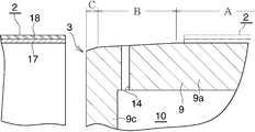
- FIG. 1 is a longitudinal sectional view of a plate mounting apparatus for a printing press showing an embodiment of the present invention.
- FIG. 2 is an enlarged longitudinal sectional view showing a part of the plate mounting apparatus and a part of the plate (2) before being mounted on the plate mounting apparatus.
- FIG. 3 is a cross-sectional view taken along line III-III in FIG.
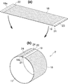
- FIG. 4 is a perspective view showing a plate and its manufacturing process.
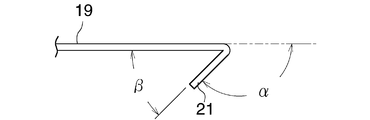
- FIG. 5 is an enlarged side view showing a part of the sheet before plate formation in FIG.
- FIG. 1 is a longitudinal sectional view of a plate mounting device (3) mounted on a plate driving shaft (1) of a printing press and mounted with a plate (2)
- FIG. 2 is a part of the plate mounting device (3) and the mounting thereof.
- FIG. 3 is a cross-sectional view (transverse view) taken along the line III-III in FIG. 1
- FIG. 4 is a view of the plate (2) and its part.
- FIG. 5 is an enlarged side view showing a part of the state before the plate formation of FIG. 4.
- the top and bottom of FIG. 1 are the top and bottom, the left side of FIG. 1 is the front, the right side is the back, and the left and right when viewing from the front to the back is the left and right.
- (4) is a thick plate-like machine frame of the printing machine that spreads up, down, left and right
- (5) is a bearing housing provided on the rear side of the machine frame (4).
- the front portion of the plate drive shaft (1) is rotatably supported by the bearing housing (5), and the rear portion is rotatably supported by a bearing housing (not shown).
- the shaft (1) is rotated at a predetermined speed in a predetermined direction (clockwise as viewed from the front in this example) by known driving means.
- the portion near the front end of the shaft (1) passes through the inside of the circular hole (6) formed in the machine frame (4) and protrudes forward from the machine frame (4), and the inner periphery of the hole (6) Is provided with an oil seal (7) for sealing between the shaft (1).
- a tapered taper portion (1a) is formed at the front end portion of the shaft (1) in front of the machine frame (4).
- a short cylindrical portion (8) protruding forward is formed concentrically with the hole (6) at a portion outside the hole (6) on the front surface of the machine frame.
- the plate mounting device (3) is fixed to the shaft taper portion (1a) so as to be detachable.
- the plate mounting device (3) includes a plate cylinder portion (9) fixed to the shaft taper portion (1a).
- the plate cylinder part (9) includes an outer cylindrical part (9a) concentric with the shaft (1), an inner tapered cylindrical part (9b) concentric with the cylindrical part (9a) and having a small front diameter, and a tapered part with the cylindrical part (9a). Consists of a front end wall (9c) connecting the front end portions of the cylindrical portion (9b) and a rear end wall (9d) connecting the rear end portions, and an annular space surrounded by these is an air chamber (10) It has become.
- the plate cylinder portion (9) is fitted to the shaft taper portion (1a) so that the inner peripheral surface of the taper tube portion (9b) is in close contact with the outer peripheral surface of the shaft taper portion (1a), and is fixed by an appropriate means (not shown).
- the plate cylinder part (9) is made of an appropriate magnetic or non-magnetic metal. In this example, it is made of SS steel, which is a general structural steel. Further, the cylindrical portion (9a), the tapered cylindrical portion (9b), and the front and rear end walls (9c) and (9d) are relatively thick in terms of strength.
- the rear part of the cylindrical part (9a) extends rearward from the rear end wall (9d) and projects outside the short cylindrical part (8) of the machine frame (4).
- An oil seal (11) is provided on the inner periphery of the rear end of the cylindrical portion (9a) to seal the space between the short cylindrical portion (8), and an annular shape is provided between the rear end wall (9d) and the machine frame (4).
- a sealed space (12) is formed.
- a plurality of communication holes (13) for communicating the air chamber (10) and the sealed space (12) are formed in the rear end wall (9d).
- a plurality of air outlet holes (14) are provided in the circumferential direction in two or more places in the front and rear portions of the cylindrical portion (9a) facing the air chamber (10), in this example, the front end portion and the rear end portion. It is formed at intervals.
- the machine frame (4) of the printing press has an air passage (16) connected to the compressed air source (15) and communicating with the sealed space (12).
- the compressed air source (15), the air passage (16), the sealed space (12) and the communication hole (13) constitute an air supply means.
- the outer diameter of the portion A of the cylindrical portion 9a on the rear side from the position slightly rearward of the front outflow hole 14 is uniform, and the front end of the portion A and the outflow hole 14 )
- the outer diameter of the part B between the positions closer to the front is gradually smaller as it goes forward, and the outer diameter of the part C on the front side of the part B is smaller as it goes further forward.
- the outer diameter of the portion A of the cylindrical portion (9a) is 220 mm
- the difference between the outer diameters of the front ends of the portion A and the portion B is about 0.2 mm.
- Plate (2) has a cylindrical shape.
- the plate (2) is composed of a cylindrical plate body (17) and a plate portion (18).
- the plate body (17) is formed in a cylindrical shape by overlapping and joining both ends of a rectangular elastic material sheet (19) as shown in FIG. 4 (a).
- the thickness of the sheet (19) may be such that it can be formed in a cylindrical shape and can be held by an elastic force. In this example, it is about 0.24 mm.
- the inner diameter of the plate body (17) is slightly smaller than the outer diameter of the portion A of the cylindrical portion (9a) of the plate cylinder portion (9), and is almost equal to the outer diameter of the portion immediately after the outflow hole (14) of the portion B. equal.
- the plate body (17) is made of a suitable metal that is magnetic or non-magnetic. In this example, it is made of SS steel, which is a general structural steel.
- the joining means of the sheet (19) is arbitrary, but in this example, an adhesive and spot welding are used.
- the plate portion (18) is provided at a predetermined position on the outer periphery excluding the joint portion (20) of the plate body (17), and the outer peripheral surface of the plate portion (18) is the plate surface.
- the end portion of the sheet (19) located inside the joining portion (20) is bent inward to form the engaging portion (21).
- the angle ⁇ at which the engaging portion (21) is actually bent from the flat state of the sheet (19) indicated by the broken line in FIG. 5 is the bending angle, and the engagement portion (21) and the adjacent portion of the sheet (19)
- the angle ⁇ formed is referred to as a seat / engagement portion angle.
- the folding angle ⁇ is preferably larger than 90 degrees (the sheet-engaging portion angle ⁇ is smaller than 90 degrees), and the folding angle ⁇ is 125 degrees to 145 degrees (the sheet-engaging section angle ⁇ is 55 degrees to 35 degrees).
- the bending angle ⁇ is most preferably 135 degrees (the sheet-engaging portion angle ⁇ is 45 degrees).
- the folding angle ⁇ is about 135 degrees
- the sheet-engaging portion angle ⁇ is about 45 degrees.
- a step portion is formed between the end portion (19a) of the sheet (19) located outside the joining portion (20) of the plate (2) and the central portion of the sheet (19). (22) is formed, and the inner diameter of the end (19a) is larger than the inner diameter of the other part of the sheet (19).
- the size of the step of the step portion (22) is not more than the thickness of the sheet (19).
- an engaging portion (21) is formed at one end of a rectangular sheet (19), and a step portion (22) is formed at the other end to form a sheet (19
- the plate portion (18) is formed in a predetermined portion excluding the portion near the both ends of ().
- an appropriate adhesive (23) is applied to the surface opposite to the engaging portion (21) at the end of the sheet (19) on the engaging portion (21) side.
- the sheet (19) is formed in a cylindrical shape, and the end (19a) of the opposite sheet (19) is superimposed on the outside of the adhesive (23). Further, the joined portion (20) is firmly joined by spot welding.
- (24) has shown the spot welding part.
- Formation of the plate on the plate portion (28), that is, plate making, may be performed on the plate portion (18) in the state of the sheet (19) in FIG. 4 (a), or the cylindrical shape in FIG. 4 (b). You may perform with respect to the plate part (18) of the plate (2).
- a circumferential positioning groove (25) into which the engaging portion (21) of the plate (2) is fitted is formed on the entire outer circumference of the cylindrical portion (9a) of the plate cylinder portion (9). Yes.
- the angle ⁇ formed by the groove (25) and the outer peripheral surface of the cylindrical portion (9a) is equal to the sheet-engaging portion angle ⁇ of the engaging portion (21) of the plate (2).
- the groove (25) is formed so that its bottom (25a) is located behind the opening (25b) in the rotation direction of the plate cylinder (9) (direction indicated by ⁇ R in FIG. 3).
- annular axial positioning stopper projecting radially outward from the outer peripheral surface of the cylindrical portion (9a) on the outer peripheral portion of the rear end surface of the cylindrical portion (9a) of the plate cylinder portion (9). 26) is fixed.
- Compressed air is supplied to the air chamber (10) of the plate cylinder (9) when the plate (2) is mounted on the plate cylinder (9).
- the air flows outward from the air outflow hole (14) on the outer peripheral surface of the cylindrical portion (9a).
- the outlet hole (14) When the engaging portion (21) is fitted into the groove (25) and the cylindrical plate (2) is fitted onto the outer peripheral surface of the plate cylinder portion (9), the outlet hole (14)
- the plate (2) expands in the radial direction due to the pressure of the outflowing air, the inner diameter of the plate (2) becomes larger than the outer diameter of the plate cylinder (9), and the plate is easily placed on the outer periphery of the plate cylinder (9). (2) can be fitted.
- the plate (2) comes into contact with the stopper (26) and stops, the supply of compressed air to the air chamber (10) is stopped. Then, the plate (2) contracts, comes into close contact with the outer peripheral surface of the cylindrical portion (9a), and is fixed in a press-fitted state at a position in contact with the stopper (26). At this time, the plate (2) is accurately positioned with respect to the plate cylinder portion (9) in the circumferential direction by the groove (25) and in the axial direction by the stopper (26).
- the plate cylinder part (9) is rotated while the plate (2) is fixed to the plate cylinder part (9) as described above.
- the front end side of the engaging portion (21) of the plate (2) faces the rear side in the rotation direction R, the engaging portion (21) bites into the groove (25), and the position of the plate (2) shifts. There is nothing.
- the overall configuration of the printing press, the plate mounting device (3), and the plate (2) and the configuration of each unit are not limited to those of the above-described embodiment, and can be changed as appropriate.
- the present invention is suitable for use in a printing plate and a printing press.
- the cylindrical plate can be easily and accurately attached to the plate cylinder portion fixed to the plate drive shaft of the printing press.
- the cylindrical plate can be easily removed from the part.
Landscapes
- Engineering & Computer Science (AREA)
- Mechanical Engineering (AREA)
- Supply, Installation And Extraction Of Printed Sheets Or Plates (AREA)
- Printing Plates And Materials Therefor (AREA)
- Details Of Cutting Devices (AREA)
Abstract
Description
(3) 版装着装置
(9) 版シリンダ部
(10) 空気室
(12) 密閉空間
(13) 連通穴
(14) 空気流出穴
(15) 圧縮空気源
(16) 空気通路
(17) 版本体
(18) 版部
(19) シート
(20) 接合部分
(21) 係合部
(25) 周方向位置決め用みぞ
(26) 軸方向位置決め用ストッパ (1) Plate drive shaft
(3) Plate mounting device
(9) Plate cylinder
(10) Air chamber
(12) Sealed space
(13) Communication hole
(14) Air outflow hole
(15) Compressed air source
(16) Air passage
(17) Version body
(18) Print part
(19) Seat
(20) Joint part
(21) Engagement part
(25) Groove for circumferential positioning
(26) Axial positioning stopper
Claims (5)
- 長方形状の弾性材料製シートが円筒状に形成されて両端部が重ね合わされて接合されることにより、円筒状版本体が構成され、接合部分の内側に位置するシートの端部が内側に折り曲げられて、係合部が形成されており、接合部分を除く版本体の外周面の所定箇所に、版部が設けられていることを特徴とする印刷機用版。 A rectangular elastic material sheet is formed in a cylindrical shape and both ends are overlapped and joined to form a cylindrical plate body, and the end of the sheet located inside the joined portion is folded inward. A printing plate characterized in that an engagement portion is formed, and a plate portion is provided at a predetermined location on the outer peripheral surface of the plate main body excluding the joining portion.
- 係合部の折り曲げ角度が90度より大きいことを特徴とする請求項1の印刷機用版。 2. The printing press plate according to claim 1, wherein a bending angle of the engaging portion is larger than 90 degrees.
- 円筒状の版が装着される版装着装置を備えており、
版が、長方形状の弾性材料製シートが円筒状に形成されて両端部が重ね合わされて接合されることにより、円筒状版本体が構成され、接合部分の内側に位置するシートの端部が内側に折り曲げられて、係合部が形成されており、接合部分を除く版本体の外周面の所定箇所に、版が形成された版部が設けられているものであり、
版装着装置が、版駆動軸に固定状に設けられて外周に版駆動軸の先端側から版が装着される版シリンダ部を備えており、版シリンダ部の外周に、版駆動軸の先端側から版の係合部がはめられる周方向位置決め用みぞと、版の端部が当接する軸方向位置決め用ストッパとが設けられていることを特徴とする印刷機。 Equipped with a plate mounting device on which a cylindrical plate is mounted;
The plate is formed by forming a rectangular elastic material sheet into a cylindrical shape and both ends are overlapped and joined to form a cylindrical plate body, and the end of the sheet located inside the joint is inside Are bent to form an engaging portion, and a plate portion on which a plate is formed is provided at a predetermined location on the outer peripheral surface of the plate main body excluding the joining portion,
The plate mounting device includes a plate cylinder portion that is fixed to the plate drive shaft and on which the plate is mounted from the front end side of the plate drive shaft. The front end side of the plate drive shaft is disposed on the outer periphery of the plate cylinder portion. A printing machine comprising: a circumferential positioning groove into which a plate engaging portion is fitted; and an axial positioning stopper with which an end portion of the plate abuts. - 版シリンダ部の内部に、空気供給手段により圧縮空気が供給される空気室が形成されており、版シリンダ部の先端側の外径が、先端に行くにつれて小さくなっており、この外径が小さくなった部分を含む版シリンダ部の外周面の軸方向および周方向の複数箇所に、空気室と連通する空気流出穴が形成されていることを特徴とする請求項3の印刷機。 An air chamber to which compressed air is supplied by air supply means is formed inside the plate cylinder portion, and the outer diameter on the tip side of the plate cylinder portion becomes smaller toward the tip, and this outer diameter is reduced. 4. The printing press according to claim 3, wherein air outflow holes communicating with the air chamber are formed at a plurality of locations in the axial direction and the circumferential direction of the outer peripheral surface of the plate cylinder portion including the formed portion.
- 版の係合部の折り曲げ角度が90度より大きく、版シリンダ部が、版本体を構成するシートの係合部のある端部側が回転方向前側となる方向に回転させられることを特徴とする請求項3または4の印刷機。 The folding angle of the plate engaging portion is larger than 90 degrees, and the plate cylinder portion is rotated in a direction in which an end portion side having an engaging portion of a sheet constituting the plate main body is a front side in the rotation direction. Item 3. A printing machine according to item 3 or 4.
Priority Applications (3)
| Application Number | Priority Date | Filing Date | Title |
|---|---|---|---|
| EP09754608A EP2286997A4 (en) | 2008-05-27 | 2009-05-21 | Plate for printing press and printing press |
| US12/736,913 US8635952B2 (en) | 2008-05-27 | 2009-05-21 | Machine plate for printer and printer |
| CN2009801253033A CN102076499A (en) | 2008-05-27 | 2009-05-21 | Plate for printing press and printing press |
Applications Claiming Priority (2)
| Application Number | Priority Date | Filing Date | Title |
|---|---|---|---|
| JP2008137766A JP2009285861A (en) | 2008-05-27 | 2008-05-27 | Printing plate and press |
| JP2008-137766 | 2008-05-27 |
Publications (1)
| Publication Number | Publication Date |
|---|---|
| WO2009145100A1 true WO2009145100A1 (en) | 2009-12-03 |
Family
ID=41376978
Family Applications (1)
| Application Number | Title | Priority Date | Filing Date |
|---|---|---|---|
| PCT/JP2009/059311 WO2009145100A1 (en) | 2008-05-27 | 2009-05-21 | Plate for printing press and printing press |
Country Status (7)
| Country | Link |
|---|---|
| US (1) | US8635952B2 (en) |
| EP (1) | EP2286997A4 (en) |
| JP (1) | JP2009285861A (en) |
| KR (1) | KR101618894B1 (en) |
| CN (1) | CN102076499A (en) |
| MY (2) | MY160398A (en) |
| WO (1) | WO2009145100A1 (en) |
Cited By (2)
| Publication number | Priority date | Publication date | Assignee | Title |
|---|---|---|---|---|
| CN102179992A (en) * | 2011-03-03 | 2011-09-14 | 高斯图文印刷系统(中国)有限公司 | Printing plate of flexo printing machine and installing method thereof |
| CN103153622A (en) * | 2010-10-06 | 2013-06-12 | 昭和铝罐株式会社 | Plate attachment device and method for attaching/removing printing plate |
Families Citing this family (10)
| Publication number | Priority date | Publication date | Assignee | Title |
|---|---|---|---|---|
| JP4925470B2 (en) | 2008-07-01 | 2012-04-25 | 雅幸 井爪 | Plate making machine for printing press |
| JP4925471B2 (en) | 2008-08-11 | 2012-04-25 | 雅幸 井爪 | Plate mounting apparatus for printing press and printing press |
| WO2013171818A1 (en) | 2012-05-14 | 2013-11-21 | Izume Masayuki | Printing plate unit, printing plate mounting device, and printing machine |
| JP5501486B2 (en) * | 2013-01-11 | 2014-05-21 | 昭和アルミニウム缶株式会社 | Printing method, printing plate manufacturing method and printing plate |
| RU2664239C2 (en) * | 2013-09-04 | 2018-08-15 | Ай. МЕР КО., ЛТД. | Printing plate unit, plate cylinder device and printing plate unit automatic attachment device for printer |
| JP6316121B2 (en) * | 2014-06-30 | 2018-04-25 | 昭和アルミニウム缶株式会社 | Plate cylinder, plate mounting device |
| JP6499841B2 (en) * | 2014-09-12 | 2019-04-10 | 株式会社コムラテック | Flexographic printing plate |
| JP6559411B2 (en) * | 2014-11-04 | 2019-08-14 | 昭和アルミニウム缶株式会社 | Method for forming printing plate and cylindrical forming apparatus for printing plate |
| CN105730002B (en) * | 2016-04-13 | 2019-02-05 | 上悦(上海)印刷有限公司 | A kind of soft version pastes version device automatically |
| CN106004012B (en) * | 2016-07-12 | 2019-03-08 | 云维健 | The pressure roller of adagio printing machine improves structure and its flexo method of plate installation |
Citations (4)
| Publication number | Priority date | Publication date | Assignee | Title |
|---|---|---|---|---|
| JPH05116271A (en) * | 1991-10-28 | 1993-05-14 | Toppan Printing Co Ltd | Printing cylinder of sleeve type printing press |
| JPH06328657A (en) * | 1993-05-13 | 1994-11-29 | Man Roland Druckmas Ag | Registering device for sleeve-form offset plate |
| JP2000103036A (en) * | 1998-09-29 | 2000-04-11 | Man Roland Druckmas Ag | Method for fitting printing plate to plate cylinder and fitting device |
| JP2000508983A (en) * | 1996-04-26 | 2000-07-18 | ハイデルベルガー ドルツクマシーネン アクチエンゲゼルシヤフト | Plate cylinder with plate mounting device for fixed fastening |
Family Cites Families (11)
| Publication number | Priority date | Publication date | Assignee | Title |
|---|---|---|---|---|
| US3639959A (en) * | 1970-03-23 | 1972-02-08 | Armstrong Cork Co | Glass fiber cord rubber roller |
| IN146438B (en) * | 1976-01-08 | 1979-06-02 | Strachan & Henshaw Ltd | |
| JPS63293058A (en) * | 1987-05-25 | 1988-11-30 | Mitsubishi Paper Mills Ltd | Plate bending shaft for offset rotary printing press and press plate setting method using said shaft |
| IT1231223B (en) | 1987-09-11 | 1991-11-26 | Cerutti Spa Off Mec | METHOD FOR JOINING THE ENDS OF A SHEET FOR ROTARY PRINTING AND JOINTING SO OBTAINED |
| JPH0511627A (en) | 1991-06-28 | 1993-01-22 | Nec Corp | Electrophotographic recorder |
| DE4341262C2 (en) * | 1993-01-22 | 1999-04-08 | Heidelberger Druckmasch Ag | Device for reducing bulges of material on a tubular pressure sleeve |
| US5535674A (en) * | 1994-06-24 | 1996-07-16 | Heidelberger Druckmaschinen Ag | Distortion-reduced lithographic printing press |
| DE19524707C2 (en) * | 1995-07-10 | 2001-03-01 | Polywest Kunststofftechnik | Process for producing a seamless printing sleeve, in particular for a flexographic printing cylinder |
| US5711222A (en) * | 1996-06-14 | 1998-01-27 | Heidelberger Druckmaschinen Ag | Method and apparatus for mounting a flat printing plate on a cantilevered plate cylinder of a printing press |
| US6394943B1 (en) * | 2000-05-19 | 2002-05-28 | Steven Cormier | Image transfer drum for document printer/copier |
| EP1362697B1 (en) * | 2002-05-18 | 2005-04-06 | Fischer & Krecke Gmbh & Co. | Device for handling printing sleeves |
-
2008
- 2008-05-27 JP JP2008137766A patent/JP2009285861A/en active Pending
-
2009
- 2009-05-21 EP EP09754608A patent/EP2286997A4/en not_active Withdrawn
- 2009-05-21 MY MYPI2011000193A patent/MY160398A/en unknown
- 2009-05-21 US US12/736,913 patent/US8635952B2/en not_active Expired - Fee Related
- 2009-05-21 WO PCT/JP2009/059311 patent/WO2009145100A1/en active Application Filing
- 2009-05-21 CN CN2009801253033A patent/CN102076499A/en active Pending
- 2009-05-21 MY MYPI2010005595A patent/MY154231A/en unknown
- 2009-05-21 KR KR1020107027977A patent/KR101618894B1/en active IP Right Grant
Patent Citations (4)
| Publication number | Priority date | Publication date | Assignee | Title |
|---|---|---|---|---|
| JPH05116271A (en) * | 1991-10-28 | 1993-05-14 | Toppan Printing Co Ltd | Printing cylinder of sleeve type printing press |
| JPH06328657A (en) * | 1993-05-13 | 1994-11-29 | Man Roland Druckmas Ag | Registering device for sleeve-form offset plate |
| JP2000508983A (en) * | 1996-04-26 | 2000-07-18 | ハイデルベルガー ドルツクマシーネン アクチエンゲゼルシヤフト | Plate cylinder with plate mounting device for fixed fastening |
| JP2000103036A (en) * | 1998-09-29 | 2000-04-11 | Man Roland Druckmas Ag | Method for fitting printing plate to plate cylinder and fitting device |
Non-Patent Citations (1)
| Title |
|---|
| See also references of EP2286997A4 * |
Cited By (2)
| Publication number | Priority date | Publication date | Assignee | Title |
|---|---|---|---|---|
| CN103153622A (en) * | 2010-10-06 | 2013-06-12 | 昭和铝罐株式会社 | Plate attachment device and method for attaching/removing printing plate |
| CN102179992A (en) * | 2011-03-03 | 2011-09-14 | 高斯图文印刷系统(中国)有限公司 | Printing plate of flexo printing machine and installing method thereof |
Also Published As
| Publication number | Publication date |
|---|---|
| EP2286997A4 (en) | 2012-02-22 |
| MY154231A (en) | 2015-05-15 |
| JP2009285861A (en) | 2009-12-10 |
| KR20110016939A (en) | 2011-02-18 |
| US20110061551A1 (en) | 2011-03-17 |
| CN102076499A (en) | 2011-05-25 |
| KR101618894B1 (en) | 2016-05-09 |
| EP2286997A1 (en) | 2011-02-23 |
| MY160398A (en) | 2017-03-15 |
| US8635952B2 (en) | 2014-01-28 |
Similar Documents
| Publication | Publication Date | Title |
|---|---|---|
| WO2009145100A1 (en) | Plate for printing press and printing press | |
| WO2010018702A1 (en) | Device for attaching plate to printing press and printing press | |
| JP5722586B2 (en) | Plate mounting apparatus and printing plate attaching / detaching method | |
| JP2767619B2 (en) | Small-diameter piping end mutual connector | |
| WO2010001667A1 (en) | Printer plate manufacturing apparatus | |
| JP2009285861A5 (en) | ||
| JP2000103036A (en) | Method for fitting printing plate to plate cylinder and fitting device | |
| JP5560000B2 (en) | Plate for printing press and plate mounting device | |
| KR20180042959A (en) | Printer Unit | |
| JP5501486B2 (en) | Printing method, printing plate manufacturing method and printing plate | |
| JP2004090877A (en) | Fuel feed pipe | |
| JP5468520B2 (en) | Plate mounting apparatus and plate mounting method | |
| JP2019202892A (en) | Winding core, winding core rotation device, and winding method | |
| JP3956140B2 (en) | Thermal transfer printer and image forming apparatus | |
| JPH04128849A (en) | Image forming device | |
| JP2010038195A (en) | Torque rod and manufacturing method therefor | |
| JP4918309B2 (en) | Film forming roll, outer cylinder for film forming roll, and film forming machine | |
| JP2008064289A (en) | Spring clamp | |
| JP2005313176A (en) | Method for manufacturing silencer for vehicle | |
| JP2015189335A (en) | Housing structure of steering column | |
| JP2005337036A (en) | Connecting method of exhaust pipe in vehicular muffler | |
| JP5636197B2 (en) | Pipe end straightening device | |
| JP2005201151A (en) | Method of manufacturing muffler for vehicle | |
| JPS6221654A (en) | Lug installation structure for tape taking-up apparatus | |
| JP2002235732A (en) | Roller and manufacturing method for roller |
Legal Events
| Date | Code | Title | Description |
|---|---|---|---|
| WWE | Wipo information: entry into national phase |
Ref document number: 200980125303.3 Country of ref document: CN |
|
| 121 | Ep: the epo has been informed by wipo that ep was designated in this application |
Ref document number: 09754608 Country of ref document: EP Kind code of ref document: A1 |
|
| WWE | Wipo information: entry into national phase |
Ref document number: 12736913 Country of ref document: US |
|
| WWE | Wipo information: entry into national phase |
Ref document number: 4431/KOLNP/2010 Country of ref document: IN |
|
| WWE | Wipo information: entry into national phase |
Ref document number: 2009754608 Country of ref document: EP |
|
| NENP | Non-entry into the national phase |
Ref country code: DE |
|
| ENP | Entry into the national phase |
Ref document number: 20107027977 Country of ref document: KR Kind code of ref document: A |