WO2009128400A1 - Device and method for altering the crank arm radius of gyration, and drive apparatus comprising the device - Google Patents
Device and method for altering the crank arm radius of gyration, and drive apparatus comprising the device Download PDFInfo
- Publication number
- WO2009128400A1 WO2009128400A1 PCT/JP2009/057345 JP2009057345W WO2009128400A1 WO 2009128400 A1 WO2009128400 A1 WO 2009128400A1 JP 2009057345 W JP2009057345 W JP 2009057345W WO 2009128400 A1 WO2009128400 A1 WO 2009128400A1
- Authority
- WO
- WIPO (PCT)
- Prior art keywords
- crank arm
- arm
- crank
- drive shaft
- engagement
- Prior art date
Links
Images


Classifications
-
- F—MECHANICAL ENGINEERING; LIGHTING; HEATING; WEAPONS; BLASTING
- F16—ENGINEERING ELEMENTS AND UNITS; GENERAL MEASURES FOR PRODUCING AND MAINTAINING EFFECTIVE FUNCTIONING OF MACHINES OR INSTALLATIONS; THERMAL INSULATION IN GENERAL
- F16H—GEARING
- F16H21/00—Gearings comprising primarily only links or levers, with or without slides
- F16H21/10—Gearings comprising primarily only links or levers, with or without slides all movement being in, or parallel to, a single plane
- F16H21/40—Gearings comprising primarily only links or levers, with or without slides all movement being in, or parallel to, a single plane for interconverting rotary motion and oscillating motion
- F16H21/42—Gearings comprising primarily only links or levers, with or without slides all movement being in, or parallel to, a single plane for interconverting rotary motion and oscillating motion with adjustable throw
-
- B—PERFORMING OPERATIONS; TRANSPORTING
- B60—VEHICLES IN GENERAL
- B60S—SERVICING, CLEANING, REPAIRING, SUPPORTING, LIFTING, OR MANOEUVRING OF VEHICLES, NOT OTHERWISE PROVIDED FOR
- B60S1/00—Cleaning of vehicles
- B60S1/02—Cleaning windscreens, windows or optical devices
- B60S1/04—Wipers or the like, e.g. scrapers
- B60S1/06—Wipers or the like, e.g. scrapers characterised by the drive
- B60S1/16—Means for transmitting drive
- B60S1/18—Means for transmitting drive mechanically
- B60S1/24—Means for transmitting drive mechanically by rotary cranks
- B60S1/245—Means for transmitting drive mechanically by rotary cranks with particular rod arrangements between the motor driven axle and the wiper arm axle
-
- F—MECHANICAL ENGINEERING; LIGHTING; HEATING; WEAPONS; BLASTING
- F16—ENGINEERING ELEMENTS AND UNITS; GENERAL MEASURES FOR PRODUCING AND MAINTAINING EFFECTIVE FUNCTIONING OF MACHINES OR INSTALLATIONS; THERMAL INSULATION IN GENERAL
- F16C—SHAFTS; FLEXIBLE SHAFTS; ELEMENTS OR CRANKSHAFT MECHANISMS; ROTARY BODIES OTHER THAN GEARING ELEMENTS; BEARINGS
- F16C3/00—Shafts; Axles; Cranks; Eccentrics
- F16C3/04—Crankshafts, eccentric-shafts; Cranks, eccentrics
- F16C3/22—Cranks; Eccentrics
-
- F—MECHANICAL ENGINEERING; LIGHTING; HEATING; WEAPONS; BLASTING
- F16—ENGINEERING ELEMENTS AND UNITS; GENERAL MEASURES FOR PRODUCING AND MAINTAINING EFFECTIVE FUNCTIONING OF MACHINES OR INSTALLATIONS; THERMAL INSULATION IN GENERAL
- F16C—SHAFTS; FLEXIBLE SHAFTS; ELEMENTS OR CRANKSHAFT MECHANISMS; ROTARY BODIES OTHER THAN GEARING ELEMENTS; BEARINGS
- F16C2326/00—Articles relating to transporting
- F16C2326/01—Parts of vehicles in general
- F16C2326/09—Windscreen wipers, e.g. pivots therefore
Definitions
- the present invention relates to a crank arm turning radius changing device, a changing method thereof, and a driving device including the changing device.
- the crank mechanism converts the rotational driving force of a driving means such as a motor into a reciprocating linear motion of a link arm connected to the crank arm.
- crank arm rotation radius changing device for changing the rotation radius of the crank arm by moving the position of the connecting shaft during rotation of the crank arm (see, for example, Patent Documents 1 to 5).
- JP 2006-161999 A paragraphs 0009 to 0017, paragraph 0029, FIGS. 1 and 2) Japanese Patent Laying-Open No. 2005-80993 (paragraphs 0049 to 0067, FIGS. 2 to 4) JP-T-2001-519690 (9th page, 24th line to 11th page, 17th line, FIG. 2) Japanese Patent Laid-Open No. 10-169745 (paragraphs 0011 to 0015, FIGS. 1 to 4) Japanese Utility Model Publication No. 3-125655 (page 9, line 10 to page 11, line 17, Fig. 2)
- the crank arm turning radius changing device described in Patent Documents 1 and 2 includes a guide member on which a surface for restraining the position of the connecting shaft is formed, and the turning radius is changed by the guide member.
- the guide member faces the crank member and is installed independently from the crank member, there is a problem that a space for installation becomes large.
- the turning radius changing devices described in Patent Documents 3 to 5 change the turning radius by forcibly moving the connecting shaft using a driving device different from the driving device that rotates the crank member. Since a large axial force acts on the axis of the crank member, the connecting shaft and the link arm, it is great for forcibly moving the connecting shaft when the crank member rotates and the link arm reciprocates linearly. In addition to requiring power, the apparatus is operated against the axial force, so that the apparatus is liable to break down.
- the object of the present invention was made in view of such a problem.
- a natural force acting on the crank mechanism is used.
- the required power is reduced, the structure is simplified, and the installation space is suppressed.
- the crank arm rotation radius changing device is a rotation of the crank arm in a crank mechanism that converts the rotational driving force of the drive shaft into the reciprocating linear motion of the link arm by the rotation of the crank arm.
- a radius changing device wherein the turning radius changing device has a function of displacing a rotation center position of the crank arm in a length direction of the crank arm by a natural force acting on the crank mechanism. The rotation radius of the crank arm is changed, and the reciprocating linear motion stroke of the link arm is changed.
- the displacement function is fixed to the drive shaft and applied with a rotational force, and supports the crank arm so as to freely reciprocate, and restricts the reciprocating movement of the crank arm, And changing means for changing a fixing position for fixing the crank arm.
- the changing means can be configured to change the fixed position of the crank arm with respect to the support member by switching the engagement position between the crank arm and the support member.
- the changing means includes a moving body that is movably supported by the support member, an urging means that urges the moving body in an engagement direction with the crank arm, and an urging force of the urging means. And you may employ
- the support member may be configured to include a rotating body that contacts the edge of the crank arm and guides the movement of the crank arm.
- a drive device is characterized by comprising a rotation radius changing device for the crank arm and drive means for rotating the drive shaft to which the support member is fixed.
- the drive device reduces the rotational speed of the drive shaft by the drive means as the distance between the drive shaft transmitting the rotational force in the crank arm and the drive shaft increases.
- Drive control means for increasing the rotational speed of the drive shaft by the drive means as the distance from the drive shaft becomes shorter may be provided.
- a crank arm turning radius changing method is a crank arm turning radius changing method in a crank mechanism for converting a rotational driving force of a drive shaft into a reciprocating linear motion of a link arm by rotating the crank arm,
- the rotation radius changing method changes the rotation radius of the crank arm by displacing the rotation center position of the crank arm in the length direction of the crank arm by a natural force acting on the crank mechanism.
- the reciprocating linear motion stroke is changed.
- the present invention uses the natural force acting on the crank mechanism to change the rotation center position of the crank arm, so the structure is simple and the installation space can be suppressed, and the power required for moving the connecting shaft is reduced. it can.
- FIG. 5 is a plan view showing a state where the other locking member is engaged with the crank arm.
- FIG. 5 is a plan view showing a state where the other locking member is engaged with the crank arm. It is a schematic diagram showing the state of a crank arm, (a) shows the angle between the link arm and 0 °, and (b) shows the time from 0 ° to 90 °. It is a schematic diagram showing the state of a crank arm, (a) shows the angle between the link arm and 90 °, and (b) shows the interval from 90 ° to 180 °.
- FIG. 1 It is a schematic diagram showing the state of a crank arm, (a) shows the angle between the link arm and 180 °, and (b) shows the interval from 180 ° to 270 °. It is a schematic diagram showing a state of a crank arm, (a) shows the angle between the link arm and 270 °, and (b) shows the interval from 270 ° to 360 °. It is a figure which shows the example which applied the rotating radius change apparatus of the crank arm which concerns on this invention to the nozzle apparatus. It is the 1st figure which shows the further another example of application of the rotation radius change apparatus of the crank arm of this invention. It is a 2nd figure which shows the further another example of application of the rotating radius change apparatus of the crank arm of this invention. FIG.
- FIG. 17A is a side view of a crank arm turning radius changing device according to another embodiment
- FIG. 16B is a plan view of the crank arm turning radius changing device of FIG. (A) is a side view of the crank-arm turning radius changing device according to another embodiment
- (b) is a plan view of the crank-arm turning radius changing device of FIG. 17 (a).
- (a) is a top view of the apparatus
- (b) is a side view of the apparatus
- (c) is the front of the apparatus Figure.
- FIG. 19 is a cross-sectional view showing an example of a connection structure between a drive shaft and a substrate of a holder in the changing device of FIG.
- FIG. 19 is an explanatory diagram of an example in which a commercially available bearing is used instead of the roller 7 in FIG. 19 in the changing device of FIG.
- FIG. 19 is a plan view of the device to which the bearing is applied, and (b) is a bearing applied.
- FIG. 18 (a) and FIG. 24 (a) and FIG. 4 (b) are explanatory views of an example in which a motor driving device is employed instead of the solenoid shown in FIG.
- FIG. 27 is a detailed explanatory view of the motor drive device shown in FIG. 26, in which (a) is a plan view of a cross section of the motor drive device, and (b) is a cross-sectional view taken along line AA.
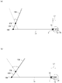
- FIG. 1 is a schematic view of an example in which a turning radius changing device (hereinafter referred to as changing device 10) of a crank arm 1 according to the present invention is applied to a wiper device 100 of an automobile.
- the changing device 10 of the present invention can be applied to various devices such as, for example, other devices for automobiles, vehicles and processing devices other than automobiles, and game machines, in addition to the wiper device 100 for automobiles.
- a wiper device 100 is installed in, for example, a body A of an automobile, and the power of a motor (driving means) 2 fixed to any part of the body A is connected to a crank arm 1.
- the wiper arm 13 is converted to reciprocating swing, and the windshield 19 is wiped by the wiping body 14 connected to the tip of the wiper arm 13.
- the crank arm 1 is rotatably connected to the link arm 11 by a connecting shaft 16 and supported by a holder (support member) 3.
- the crank arm 1 rotates together with the holder 3 to which a rotational force is applied to the drive shaft 21 of the motor 2,
- the arm 11 is reciprocated linearly along its length.
- the link plate 12 is integrally connected or joined to the base of the wiper arm 13.
- the link plate 12 is rotatably supported by a pivot shaft 17 fixed to the body A. When a linear motion is transmitted from the link arm 11, the link plate 12 swings around the pivot shaft 17 and swings the wiper arm 13.
- the wiper arm 13A disposed on the passenger seat side and the wiper arm 13B disposed on the driver seat side are provided side by side.
- a connecting link arm 15 is provided between the link plates 12A and 12B connected to the wiper arms 13A and 13B.
- the link plate 12A is rotatably supported on the link arm 11 by a pin 18A at one end, and is rotatably supported by the body A by a pivot shaft 17A, integrated with the wiper arm 13A at the other end.
- the link plate 12B is rotatably supported on the connecting link arm 15 at one end by a pin 18B, and is integrated with the wiper arm 13B at the other end to be rotatably supported on the body A by a pivot shaft 17B.
- the connecting link arm 15 is rotatably supported by the pin 18A together with the link plate 12B, linearly moves together with the link arm 11, and rotates the link plate 12B in conjunction with the swing of the link plate 12A.
- the changing device 10 has a function of displacing the rotation center position of the crank arm 1 in the crank arm length direction, and changes the rotation radius of the crank arm 1 by the displacement, thereby linking the link arm. 11 reciprocating linear motion strokes are changed.
- the displacement function of the changing device 10 is fixed to the drive shaft 21 of the motor 2 and is given a rotational force, and a holder 3 as a support member that supports the crank arm 1 so as to be reciprocally movable in its length direction; And changing means 4 for changing the fixed position of the crank arm 1 with respect to the holder 3.
- the changing means 4 is activated by operation of a switching operation device 20 electrically connected to a power supply source.
- the “width direction” of the holder 3 means a direction (left-right direction in the drawing) orthogonal to the length direction of the crank arm 1 in plan view.
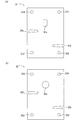
- crank arm 1 other than the relative movement in the length direction with respect to the holder 3 is constrained in a state where the crank arm 1 is inserted into the holder 3, and rotates integrally with the holder 3 by the rotation of the drive shaft 21.
- the crank arm 1 is formed with an insertion hole 1a that is inserted through the drive shaft 21 so as to be long in the length direction of the crank arm 1, for example.
- the crank arm 1 rotates around the drive shaft 21 and moves in the length direction of the crank arm 1 with respect to the drive shaft 21.
- the insertion hole 1 a is formed between a substantially middle point in the length direction of the crank arm 1 and the connecting shaft 16.
- arc-shaped convex portions 1 c are formed on both edges of the crank arm 1. Therefore, friction between the holder 3 and the crank arm 1 is reduced, and the movement of the crank arm 1 in the length direction is performed smoothly.
- the crank arm 1 includes a connecting portion 1A connected to the link arm 11 via a connecting shaft 16 and an insertion portion 1B inserted into the holder 3.
- the connecting portion 1A has, for example, an L shape, and includes a side wall 1d erected from one end of the insertion portion 1B and a top wall 1e formed from the side wall 1d toward the center of the crank arm 1.
- An insertion hole 1f into which the connecting shaft 16 is inserted is formed in the top wall 1e.
- the connecting shaft 16 is a ball joint.
- the insertion portion 1B and the top wall 1e of the connecting portion 1A are separated from each other in the axial direction of the drive shaft 21, and when the drive shaft 21 is located at the end portion closer to the connecting portion 1A of the insertion hole 1a, the top wall 1e
- the holder 3 overlaps in plan view.
- the rotation radius of the crank arm 1 can be reduced, and the installation space for the changing device 10 can be reduced.
- the movement of the crank arm 1 in the length direction relatively moves the drive shaft 21 between both end portions of the insertion hole 1a.
- the rotation center position of the crank arm 1 is displaced in the length direction of the crank arm, and the rotation radius of the crank arm 1 is the position of the drive shaft 21 in the insertion hole 1a formed in the crank arm 1, that is, the connecting shaft. 16 and the drive shaft 21 are changed according to the positional relationship.
- the distance (rotational radius) L1 from the driving shaft 21 to the connecting shaft 16 is minimized.
- the turning radius of is minimal.
- the swing range of the wiper arms 13A and 13B is twice the swing range before the change. Therefore, the maximum range in which the distance between the drive shaft 21 and the connecting shaft 16 (the rotation radius of the crank arm 1) is changed is determined according to the length and the formation position of the insertion hole 1a. For this reason, the length and formation position of the insertion hole 1a are appropriately set according to the target wiping ranges of the wiping bodies 14A and 14B.
- the formation position of the insertion hole 1a with respect to the width direction of the crank arm 1 is not limited, but when it is formed at the center in the width direction as shown in the drawing, the drive shaft 21 should not be eccentric to the crank arm 1 and the holder 3. Therefore, the region through which these rotations pass is minimum in the crank arm 1 and the holder 3 having the same size, which is preferable.
- a plurality of engagement notches 1b are formed on the edge (outer side surface) of the crank arm 1, and engagement members (moving bodies) 41 and 42 constituting the changing means 4 described later are engaged with the engagement notches 1b.
- the mating pieces 41a and 42a are engaged.
- the engagement notch 1b is formed at the edge.
- the engagement pieces 41a and 42a are separately provided on both sides of the crank arm 1, the engagement notches 1b are also formed on both edges. That is, the shape / position of the engagement notch 1b corresponds to the shape / position of the engagement pieces 41a, 42a.
- the holder 3 is nipped and fixed by, for example, two bolts 22 attached to the drive shaft 21, and is driven while being inserted through the drive shaft 21.
- Two flat substrates 31 and 32 arranged in parallel in the axial direction of the shaft 21 (vertical direction in the figure), and a rotating body 34 in contact with the edge of the crank arm 1 are provided.
- the board 31 and the board 32 have insertion holes 31 a and 32 a that are inserted into the drive shaft 21, and engagement pieces 41 a and 42 a of the engagement members 41 and 42, respectively.
- Insertion notches 31b and 32b to be inserted and rotation shaft member holes 31d and 32d to be inserted into the rotation shaft member 34A of the rotating body 34 are formed at predetermined positions.
- the opposite ends of the predetermined section in the axial direction from the tip of the drive shaft 21 are cut in the axial direction.
- the insertion hole 31 a of the substrate 31 is formed in a shape that can be fitted to the drive shaft 21.
- the rotating body 34 includes a rotating shaft member 34A that is fixed between the substrates 31 and 32, and a rotating member 34B that is rotatably supported by the rotating shaft member 34A. At least one rotating body 34 is disposed on each edge of the crank arm 1.
- the rotating shaft member 34A includes a pair of male screws and female screws, and a washer 34C is disposed as appropriate.
- an arc-shaped recess 34a is formed inward on the outer peripheral surface of the rotating member 34B over the entire circumference.
- the crank arm 1 moves in the width direction and moves in the axial direction of the rotating shaft member 34A. The movement of is restricted.
- the rotating member 34B is made of a bearing such as a ball bearing, for example. Therefore, the movement of the crank arm 1 in the length direction is smoothly performed. Further, for example, a washer is interposed between the inner ring (not shown) constituting the bearing and the substrates 31 and 32, and the male screw and the female screw are screwed together, whereby the rotating member 34B can be rotated. While maintaining, the substrates 31 and 32 can be firmly fixed to improve the structural stability of the holder 3.
- the rotation member 34B is made of a bearing, the rotation of the rotation member 34B in the axial direction of the rotation shaft member 34A is eliminated. Therefore, the crank arm 1 restrained by the rotation member 34B in the axial direction of the rotation shaft member 34A is eliminated. Restraint is also ensured.
- the convex part 1c of the crank arm 1 and the concave part 34a of the rotating member 34B are fitted, it is desirable because the restraint by the rotating body 34 of the crank arm 1 is further ensured.
- the change means 4 regulates the reciprocation of the crank arm 1 with respect to the drive shaft 21 by switching the engagement pieces 41a, 42a and the engagement notches 1b to be engaged, thereby fixing the crank arm 1 with respect to the holder 3. That is, the rotation radius of the crank arm 1 is changed.
- the changing means 4 is installed on the upper surface of the substrate 31 and moves the engaging members 41 and 42 for locking the crank arm 1 in its length direction, and the engaging members 41 and 42 in a direction away from the crank arm 1.
- a bistable self-holding solenoid hereinafter referred to as solenoid) (moving means) 43, a fixing portion 44 for fixing the solenoid 43 to the holder 3, and engaging members 41, 42 in a direction to engage the crank arm 1.
- a biasing member 45 for biasing.
- the solenoid 43 is supported and fixed by a fixing portion 44 fixed to the substrate 31.
- the fixing portion 44 includes, for example, a plurality of (two in the drawing) fixing members 44A and 44B having an L-shape, and the fixing members 44A and 44B have a length direction aligned with the width direction of the crank arm 1. Are arranged side by side in the longitudinal direction of the crank arm 1.
- Each of the fixing members 44A and 44B includes a bottom portion 44a and a side portion 44b provided continuously from the bottom portion 44a.
- the bottom portion 44a is disposed on the outer side in the longitudinal direction of the crank arm 1, and the side portion 44b is disposed on the inner side. Has been.
- Both the fixing members 44A and 44B are fixed to the substrate 31 at the bottom 44a and supported with the solenoid 43 sandwiched between the side portions 44b.
- the bottom portions 44a of the fixing members 44A and 44B are sandwiched between the female screw of the fixed shaft member 34A and the substrate 31 and fixed by screwing.
- a predetermined male screw 44C is fitted into the side portion 44b from the outside and protrudes inward, and is screwed into a housing 43c that accommodates the solenoid 43 to support the housing 43c.
- a notch 44c is formed in the bottom 44a of the fixing member 44A, and the drive shaft 21 is disposed in the notch 44c. This is because the size of the holder 3 is reduced by consolidating the drive shaft 21 and the changing means 4.
- a restraining member 46 having an L shape is disposed between the fixing members 44A and 44B in a state where the length direction thereof coincides with the length direction of the fixing members 44A and 44B.
- the restraining member 46 is connected to the bottom plate 46a located at a predetermined distance from the substrate 31 between the solenoid 43 and the substrate 31, and the side plate 44b of either one of the fixing members 44A and 44B and the housing. 43c and a side plate 46b positioned between 43c and supported by male screws 44C. It is desirable that the distance between the bottom plate 46a of the restraining member 46 and the substrate 31 matches the thickness of the insertion pieces 41b and 42b of the engaging members 41 and 42 described later. This is to restrain the movement of the drive shaft 21 of the engaging members 41 and 42 in the axial direction.
- the changing means 4 has two engaging members 41 and 42, and each has the same shape and structure.
- One engagement member 41 is disposed on the other engagement member 42 in a state of being rotated 180 degrees in plan view.
- the engaging members 41 and 42 are inserted between the restraining member 46 and the substrate 31, for example, insertion pieces 41b and 42b having a rectangular shape in plan view, and one end.
- insertion pieces 41b and 42b having a rectangular shape in plan view, and one end.
- transmission pieces 41 c and 42 c that receive the load of the solenoid 43.
- the insertion pieces 41b and 42b are inserted between the restraining member 46 and the substrate 31 so that the long side direction thereof coincides with the width direction of the crank arm 1,
- the crank arm 1 is juxtaposed in the length direction. Since the distance between the side portions 44b and 44b of the fixing members 44A and 44B is equal to the sum of the short side lengths of the insertion pieces 41b and 42b arranged side by side, the insertion pieces 41b and 42b are mutually connected on the inner surface.
- the insertion pieces 41b and 42b are constrained in the length direction of the crank arm 1 because they are in contact with and contact the side portions 44b of the fixing members 44A and 44B facing each other on the outer surface.
- the insertion pieces 41 b and 42 b are also restrained in the axial direction of the drive shaft 21. It is movable only in the long side direction (width direction of the crank arm 1).
- arc-shaped convex portions 41d and 42d are formed outwardly at both edges of the insertion pieces 41b and 42b.
- the engagement pieces 41 a and 42 a are located on the outer side in the length direction of the crank arm 1, and the engagement piece of one engagement member 41 A predetermined distance is secured between 41 a and the engagement piece 42 a of the other engagement member 42. Further, the engagement pieces 41 a and 42 a protrude toward the base end side of the drive shaft 21 and intersect the axial direction of the crank arm 1.
- the engagement piece 41a and the engagement piece 42a are disposed at a predetermined distance in the length direction of the crank arm 1, whereas the engagement notch 1b is the length of the crank arm 1. They are formed at substantially the same position in the vertical direction. That is, the positional relationship between the engagement pieces 41a and 41b is different from the positional relationship between the engagement notches 1b and 1b. Accordingly, the two engagement pieces 41a and 42a are not inserted into the engagement notch 1b at the same time. Further, the fixed position of the crank arm 1 with respect to the holder 3, that is, the distance between the drive shaft 21 and the connecting shaft 16 is determined by the positional relationship between the engagement notch 1b and the engagement pieces 41a and 42a in the length direction of the crank arm 1. Is done.
- the engagement pieces 41 a and 42 a are formed longer than the axial length of the drive shaft 21 of the holder 3 and are inserted into the insertion cutouts 31 b and 32 b of both the boards 31 and 32 and the engagement cutout 1 b of the crank arm 1. .
- the engagement pieces 41 a and 42 a may be shorter than the axial length of the drive shaft 21 of the holder 3 as long as the engagement pieces 41 a and 42 a are inserted and engaged with the engagement notches 1 b of the crank arm 1.
- the engagement pieces 41a and 42a are fixed when the engagement pieces 41a are inserted into the insertion notches 31b and 32b of the two substrates 31 and 32 having a predetermined distance. This is preferable because it can be ensured.
- Arc-shaped convex portions 41e and 42e are formed outward on the side surfaces of the engagement pieces 41a and 42a that face the crank arm 1, and the friction coefficient between the engagement pieces 41a and 42a and the crank arm 1 is reduced.
- the transmission pieces 41c and 42c protrude in the opposite direction (upper side in the drawing) to the engagement pieces 41a and 42a and face the solenoid 43.
- the transmission pieces 41c and 42c may be constituted by a single piece, and as shown in FIGS. 6A to 6D, the transmission pieces 41c and 42c are connected and transmitted to the transmission pieces 41c and 42c by, for example, a set of bolts and nuts. It is also possible to fix the pieces 41f and 42f and form them integrally.
- the transmission pieces 41c and 42c protrude outward from the positions of the side walls 44b of both the fixing members 44A and 44B in the length direction of the crank arm 1, and the protruding portion (hereinafter referred to as the protruding portion) has a biasing member 45.
- the urging member 45 is composed of, for example, an elastic body such as a spring, and is laid between opposing projecting portions.
- the urging direction of the urging member 45 coincides with the long side direction of the insertion pieces 41b and 42b. Therefore, the long side direction movement of the insertion pieces 41a and 42a of the engaging members 41 and 42 is performed smoothly.
- the solenoid 43 is connected to a movable iron core (not shown) and has output shafts 43a and 43b arranged coaxially, and the output shaft 43a, 43b moves integrally in the axial direction.
- the axial direction of the output shafts 43a and 43b is orthogonal to the length direction of the crank arm 1 in plan view, and is opposed to one of the transmission pieces 41c and 42c of the engaging members 41 and 42, respectively. .
- the output shafts 43a and 43b protrude from both end faces of a housing 43c that houses a movable iron core and a fixed iron core (not shown).
- the output shaft is oriented in a direction corresponding to the flowing current. 43a and 43b move, and either one of the output shafts 43a and 43b protrudes from the end face of the housing 43c.
- a lead wire (not shown) connected to the solenoid 43 is inserted into a through hole (not shown) formed in the drive shaft 21, and a base end portion (for example, the drive shaft 21) This is performed by being connected to a rotating contact conductor (brush) (not shown) such as a copper plate / copper foil installed in the worm gear).
- the connecting conductor is electrically connected to a predetermined power supply source via a switching operation unit 20 such as a switching switch for switching the direction of the current flowing through the solenoid 43.
- the output shaft 43a protrudes from the end face of the housing 43c so as to abut against the transmission piece 41c of the engagement member 41, and the engagement piece 41a of the engagement member 41 is released.
- the biasing member 45 is in a biased state, and biases the engaging member 41 inward in the width direction of the crank arm 1.
- the transmission piece 42c of the engagement member 42 is located away from the tip of the output shaft 43b, and the engagement piece 41a and the engagement notch 1b face each other. It is not opposed to 1 b, and is biased by the biasing member 45 and locked to the edge of the crank arm 1.
- the engaging member 41 is locked to the output shaft 43a, and the engaging member 42 is locked to the crank arm 1 outward in the width direction of the crank arm 1, and at the same time, the biasing member 45 is applied inward in the width direction of the crank arm 1. Therefore, it is restrained by the crank arm 1 restrained by the holder 3 or the moving means 43 fixed to the holder 3, so that the engagement members 41, 42 are prevented from being detached from the changing means 4.
- the engagement notch 1 b formed on the engagement piece 42 a side of the engagement member 42 is an engagement piece of the engagement member 42 in the length direction of the crank arm 1.
- the engaging member 41 is locked to the output shaft 43a, so that only the engaging member 42 of the crank arm 1 is moved by the biasing member 45 as shown in FIG. It moves inward in the width direction, and the engagement piece 42a is inserted into the engagement notch 1b and engaged.
- the crank arm 1 is engaged with the engagement piece 41a, and the movement of the crank arm 1 in the length direction is restricted.
- the urging member 45 is in the urging state in order to prevent the engagement members 41 and 42 from being detached from the changing means 4.
- the crank arm 1 moves in the length direction, and the engagement piece 41a and the engagement notch formed at the edge of the crank arm 1 facing the engagement piece 41a. 1b and the crank arm 1 at the same position in the length direction, the engagement piece 41a is inserted into the engagement notch 1b by the urging force of the urging member 45 as shown in FIG. Engage with the arm 1.
- crank arm 1 and the link arm 11 are rotatably connected via the connecting shaft 16, the crank arm 1 rotates about the connecting shaft 16 with respect to the link arm 11. That is, the angle ⁇ between the crank arm 1 and the link arm 11 changes from 0 ° to 360 ° with the connecting shaft 16 as the apex.
- crank arm 1 and the link arm 11 When the angle ⁇ between the crank arm 1 and the link arm 11 is 0 ° (360 °), the crank arm 1 and the link arm 11 are coaxial, and the drive shaft 21 is between the pin 18A and the connecting shaft 16. Is located, and the turning radius of the crank arm 1 is minimum.
- crank arm 1 When the driving means 2 is driven and the crank arm 1 starts to rotate clockwise, the crank arm 1 is connected to the connecting shaft 16 by the frictional force between the wiping bodies 14A and 14B and the windshield 19 as shown in FIG. As a result, the crank arm 1 moves in the length direction so that the drive shaft 21 moves to the end of the insertion hole 1a opposite to the connecting shaft 16. Thereby, the rotation center position of the crank arm 1 is displaced in the crank arm length direction (specifically, the direction in which the drive shaft 21 is relatively separated from the connecting shaft 16), and the rotation radius of the crank arm 1 is increased. .
- crank arm 1 when the angle ⁇ between the crank arm 1 and the link arm 11 is 270 °, the turning radius of the crank arm 1 is maximum. Until the angle ⁇ between the crank arm 1 and the link arm 11 reaches 360 ° (0 °), the crank arm 1 is linked to the link arm via the connecting shaft 16 by the frictional force between the wiping bodies 14A and 14B and the windshield 19. 11, the crank arm 1 moves in the length direction so that the drive shaft 21 moves to the end portion of the insertion hole 1 a near the connecting shaft 16 as shown in FIG. The turning radius of 1 becomes smaller. Thereafter, the crank arm 1 repeats the same operation.
- the crank arm 1 can be used by using the rotational movement of the crank arm 1 for reciprocating linear movement of the link arm 1. It is possible to change the rotation radius of the.
- the resistance force when transmitting through the link arm 11 is large, which is optimal for the automobile wiper device 100 of this application example. It is.
- the crank unit 1 makes one rotation by the driving unit 2 and performs two reciprocations in the length direction
- the above-described changing unit 4 when the above-described changing unit 4 is operated, the positions of the engagement pieces 41a and 42a and the engagement disengagement are determined. It can be changed to the turning radius of the crank arm 1 determined by the position of the notch 1b. Since the engagement pieces 41a and 42a to be engaged with the crank arm 1 can be selected by the switching operation device 20, the turning radius of the crank arm 1 can be automatically changed from the outside.
- the existing crank mechanism for transmitting the power of the driving means 2 to the link arm 11 and the changing device 10 are exchanged, the existing link mechanism for transmitting the power by the link arm 11 can be used, which is economical.
- the wiping body 14 does not cause an overload on the drive unit 2. It is possible to increase the number of wiping operations per unit time. Specifically, the longer the distance between the connecting shaft 16 that is the transmission position of the rotational force by the crank arm 1 and the driving shaft 21, the lower the rotational speed of the driving shaft 21 by the driving means 2 and the driving of the connecting shaft 16 and the driving shaft 21. Increasing the number of reciprocating motions of the link arm 11 while suppressing a significant increase in the load of the driving means 2 by increasing the rotational speed of the driving shaft 21 by the driving means 2 as the distance from the shaft 21 becomes shorter. Can do.
- the drive shaft 21 is driven by the drive means 2.
- the number of wiping operations of the wiping body 14 per unit time can be doubled while keeping the load of the driving means 2 as it is.
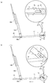
- FIG. 13 is a view showing an example in which the turning radius changing device 10 for the crank arm 1 according to the present invention is applied to the nozzle device 200.
- the same names and symbols are used for portions common to the first embodiment, and description thereof is omitted.
- the nozzle device 200 of this application example shown in FIG. 13 is an artificial rain device that sprays water on the windshield of an automobile.
- the changing device 10 a nozzle 61 that is connected to a hose and injects water, and moves the nozzle 61.
- the rails 63 are arranged such that their length directions coincide with the horizontal direction, and are connected to each other.
- the rail 63 is composed of a pair of angles (equal side angle or unequal side angle) of the same standard, and the side plate of each angle is disposed on the outside and the bottom plate is disposed on the inside.
- a guide portion 64 that guides the movable frame body 62 is formed in the length direction of the rail 63.
- the guide portion 64 is a round bar, but is set appropriately.
- the movable frame body 62 includes a pulley 621 that is movable along the guide portion 64.
- the movable frame body 62 is mounted so that the pulley 621 is fitted to a pair of guide portions 64 provided in the rail 63 and linearly movable in the length direction of the rail 63 so that the plane on which the nozzle 61 is installed intersects the horizontal plane. Has been.
- the holder 3 is supported by the drive shaft 21 of the motor 2 disposed at one end of the rail 63 so that the rotation surface of the crank arm 1 intersects the horizontal plane.
- the link arm 11 is rotatably supported on the crank arm 1 by a connecting shaft 16 at one end, and is rotatably connected to the movable frame body 62 via a pin 18A at the other end.
- movable frame bodies 62A and 62B and nozzles 61A and 61B arranged on the driver's seat side and movable frame body 62C and nozzle 61C arranged on the passenger seat side are arranged in parallel.
- a connecting link arm 65 is installed between the movable frame bodies 62A and 62B and between the movable frame bodies 62B and 62C, and the movable frame bodies 62A to 62C are connected.
- the movable frame 62C and the crank arm 1 are connected via the link arm 11, and the movable frame 62C performs a reciprocating linear motion as the crank arm 1 rotates. Therefore, the movable frame bodies 62A and 62B perform the reciprocating linear motion in conjunction with the reciprocating linear motion of the movable frame body 62C.
- crank arm 1 reciprocates once in the length direction during one rotation. This is because the rotation surface of the crank arm 1 intersects the horizontal plane, and the movable frame 62 moves using the pulley 621 and the guide portion 64, so there is almost no resistance when the movable frame 62 moves. This is because there is almost no axial force acting on the crank arm 1.
- the crank arm 11 swings around the pin 18A. Therefore, the crank arm 1 moves downward also by the weight of the link arm 11. Specifically, when the connecting shaft 16 is positioned below the drive shaft 21, as shown by an arrow in FIG. 9B, the link shaft 11 moves downward due to the weight of the link arm 11, and the drive shaft 21 is inserted into the insertion hole 1a. Even when the connecting shaft 16 is located above the drive shaft 21, it is moved downward by its own weight of the crank arm 1 as shown by an arrow in FIG. The drive shaft 21 is located at the end near the connecting shaft 16.
- the drive shaft 21 comes into contact with the end of the insertion hole 1 a far from the connecting shaft 16, and the rotation radius of the crank arm 1 is maximized.
- the drive shaft 21 comes into contact with the end of the insertion hole 1 a near the connecting shaft 16, and the rotation radius of the crank arm 1 is minimized. That is, each time the crank arm 1 makes one rotation with the holder 3 around the drive shaft 21, the crank arm 1 reciprocates once between a position where the rotation radius is maximum and a position where the rotation radius is minimum.
- the crank arm 1 By restricting the reciprocating movement and fixing the rotation radius of the crank arm 1 around the drive shaft 21, the crank arm 1 can be used by using the rotational movement of the crank arm 1 for reciprocating linear movement of the link arm 1. It is possible to change the rotation radius of the. When the rotation radius of the crank arm 1 is changed using this phenomenon, it is preferable that the resistance force when power is transmitted via the link arm 11 is small.
- the rotation radius of the crank arm 1 can be changed to be determined by the positions of the engagement pieces 41a and 42a and the position of the engagement notch 1b. Since the engagement pieces 41a and 42a to be engaged with the crank arm 1 can be selected by the switching operation device 20, the turning radius of the crank arm 1 can be automatically changed from the outside.
- the crank arm 1 is rotated vertically or obliquely with respect to the horizontal direction. Therefore, as in the second embodiment, the connection is made under the influence of gravity acting on the crank arm 1 and the link arm 11. A force acts to move the crank arm 1 with the shaft 16 positioned above or below the drive shaft 21 downward. However, when the resistance force acting via the link arm 11 is larger than that in the second embodiment, the downward movement of the crank arm 1 may be hindered by this resistance force.
- the effect of resistance increases as the number of revolutions of the crank arm 1 increases. This is because the crank arm 1 is rotated against the resistance transmitted through the link arm 11, and the crank arm 1 can move in the vertical direction without being affected by the resistance. Since the rotational position of 1 is limited, if the rotational speed is too high, the crank arm 1 will rotate to the rotational position that is greatly affected by the resistance force again before the crank arm 1 is sufficiently moved downward. It is believed that there is.
- a biasing member such as a spring may be used to constantly bias the crank arm 1 downward so that the crank arm 1 can be reliably moved downward.
- the downward urging of the crank arm 1 is preferably performed via the link arm 11. This is because when the urging member is attached to the crank arm 1 that rotates around the drive shaft 21, the arrangement and mounting structure of the urging member are limited so as to avoid contact with the holder 3 and the drive shaft 21. On the other hand, when the urging member is attached to the link arm 1, there is no such limitation.
- FIG. 14A shows a state of 90 ° while the angle between the crank arm 1 and the link arm 11 is changed from 0 ° to 90 °.
- FIG. 15A shows a state of 270 ° while the angle between the crank arm 1 and the link arm is changed from 180 ° to 270 °.
- the changing device 10 according to the present embodiment has a configuration in which the changing device 10 according to the first embodiment includes an urging member 5 installed on the link arm 11 and the body A.
- the urging member 5 is formed of an elastic body such as a spring, for example, and has one end on the crank arm 1 side from the center in the length direction of the link arm 11, and the other end at a position substantially lower than the link arm 11.
- the link arms 11 are always urged downwards, respectively.
- the crank arm 1 whose angle rotates clockwise from 0 ° to 90 ° includes the gravity acting on the crank arm 1 and the link arm 11, the tensile force of the link arm 11, and the biasing member. 5, the end of the insertion hole 1a opposite to the connecting shaft 16 is moved closer to the drive shaft 21, and the rotation radius of the crank arm 1 is increased. As shown in FIG. 14B, when the end of the insertion hole 1a opposite to the connecting shaft 16 comes into contact with the drive shaft 21, the turning radius of the crank arm 1 is maximized.
- crank arm 1 that rotates clockwise from 180 ° to 270 ° has the gravity acting on the crank arm 1 and the link arm 11 due to the tensile force of the link arm 11.
- the end of the insertion hole 1a opposite to the connecting shaft 16 moves against the driving shaft 21 against the urging force of the urging member 5, and the turning radius of the crank arm 1 increases.
- the connecting shaft 16 is positioned below the drive shaft 21 while the crank arm 1 makes one rotation with the holder 3 around the drive shaft 21.
- the urging force exerted on the crank arm 1 by the urging member 5 can be set as appropriate. For example, when the crank arm 1 rotates clockwise from 180 ° to 270 °, it is opposite to the connecting shaft 16 of the insertion hole 1a. The urging force may be applied so that the side end moves as it is without approaching the drive shaft 21.
- the mounting position of the urging member 5 can also be set as appropriate so that a sufficient urging force can be applied to the crank arm 1 via the link arm 11.
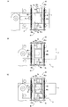
- FIG. 18 is an explanatory diagram of another embodiment of the crank arm turning radius changing device according to the present invention.
- the same names and symbols are used for portions common to the first embodiment, and description thereof is omitted.
- the strength of the rotating member 34B is improved by adopting a metal bearing such as a ball bearing as an example of the rotating member 34B described in the first embodiment.
- a metal bearing is configured such that the inner peripheral surface of the inner ring is fixed to the outer peripheral surface of the rotating shaft member 34 ⁇ / b> A, and the outer peripheral surface of the outer ring is in contact with the edge of the crank arm 1.
- the first and second substrates 31 and 32 are configured so as to restrain the movement of the crank arm 1 in the axial direction of the rotating shaft member 34A with the adoption of the bearing 34B-1.
- a plurality of rollers 7 shown in FIG. 19 are provided on the inner surface (the surface facing the crank arm 1), and a part of the outer peripheral surface of these rollers 7 is in contact with the crank arm 1 from the front and back sides of the crank arm 1.
- the plurality of rollers 7 provided on the first substrate 31 are arranged side by side along the crank arm length direction (arrow Y direction) as shown in FIGS. This also applies to the plurality of rollers 7 provided on the second substrate 32.
- the roller 7 (7A) located on the distal end side of the crank arm 1 is provided so as to be in contact with the substantially central portion in the width direction of the crank arm 1.
- two rollers 7 (7B, 7B) positioned on the rear end side of the crank arm 1 are arranged side by side in the width direction of the crank arm 11 so as to contact both edges of the insertion hole 1a of the crank arm 1. It is provided as follows. This is because the rollers 7 (7B, 7B) can reliably contact the crank arm 1 while avoiding the insertion hole 1a of the crank arm 1.
- FIG. 19 is an explanatory diagram of the roller 7 employed in the changing device 10 of FIG.
- the roller 7 in the figure has a cylindrical shape and is rotatably held by upper and lower cages 71 and 72.
- the upper cage 71 includes a recess 71A for accommodating the upper half of the roller 7 in the radial direction, an opening 71B for exposing the outer peripheral surface of the roller 7 to the outside from the bottom of the recess 71A, A bearing groove 71C that rotatably supports a shaft (hereinafter referred to as a roller shaft 70) is configured.
- the lower retainer 72 includes a recess 72 ⁇ / b> A for accommodating the lower half of the roller 7 in the radial direction.
- the upper and lower cages 71 and 72 are The upper and lower cages 71 and 12 are integrated by being fixed by a fixing means (not shown). Thereby, the roller 7 is held rotatably about the roller shaft 70, and a part of the outer peripheral surface of the roller is exposed to the outside from the opening 71 ⁇ / b> B of the upper cage 71.
- FIG. 20 is a plan view of the first and second substrates 31 and 32 used when the roller 7 of FIG. 19 is employed.
- a plurality of windows 8 for inserting the rollers 7 and the retainers 71 on the upper side thereof are opened on the substrates 31 and 32 in FIG. 20, and these windows 8 are both front and back surfaces of the substrates 31 and 32. It is formed so as to penetrate.
- FIG. 21 is an explanatory diagram showing a state in which the roller 7 is attached to installation plates 8A and 8B for installing the roller 7 of FIG. 19 on the inner surfaces of the substrates 31 and 32 of FIG.
- roller mounting recesses 80 corresponding to the window 8 of FIG. 20, as shown in FIGS. Then, by inserting the lower cage 72 of the roller 7 into the respective roller mounting recesses 80 by press-fitting, the roller 7 is integrally mounted on the installation plates 8A and 8B.
- a method of attaching the roller 7 to the installation plates 8A and 8B a method different from the above-described press fitting may be adopted.
- the installation plate 8A to which the roller 7 is attached is screwed and fixed to the substrate 31 in a state where the roller 7 and the upper retainer 71 are inserted into the window 8 of the substrate 31. Thereby, a part of the outer peripheral surface of the roller 7 (a portion exposed from the opening of the upper retainer 71 ⁇ / b> A) is exposed from the window 8 and can come into contact with the crank arm 1.
- the installation plate 8B to which the roller 7 is attached is also fixed to the substrate 32 in the same manner as the installation plate 8A described above.
- the rollers 7 of the first substrate 31 and the rollers 8 of the second substrate 32 are shown in FIGS. ) And FIG. 18B, and a part of the outer peripheral surface of the roller 7 comes into contact with the crank arm 1 from both the front and back sides of the crank arm 1. This contact restrains the movement of the crank arm 1 in the axial direction of the rotating shaft member 34A.
- roller 7 ⁇ Comparison of roller 7 and bearing BR>
- a commercially available bearing BR as shown in FIG.
- the roller 7 is compared with a bearing (commercially available product) having a load resistance specification comparable to that of the roller 7, the roller 7 has a smaller diameter and is not bulky in the thickness direction of the substrates 31 and 32, and the number of components is small and inexpensive.
- the engaging members 41 and 42 in FIG. 22 are inserted into the long holes 31f and 32f (see FIGS. 18A and 20A and 20B) of the substrates 31 and 32 to engage with the crank arm 1.
- the coupling pieces 41a, 42a, transmission pieces 41c, 42c formed integrally with the engagement pieces 41a, 42a and receiving the load of the solenoid 43, and rotating bodies 41g, 42g attached to the engagement pieces 41a, 42a. .
- the engaging members 41 and 42 in FIG. 22 are the same as the engagement members 41 and 42 in FIG. 6, and the long holes 31f and 32f of the substrates 41 and 42 (the insertion notches 31b in the engagement members 41 and 42 in FIG. 32b), and the engagement pieces 41a and 42a engage with the engagement notches 1b and 1b of the crank arm 1, thereby locking the crank arm 1 in its length direction.
- the engaging members 41 and 42 in FIG. 22 have a structure in which the convex portions 41h and 42h provided at the ends of the engaging pieces 41a and 42a engage with the engaging notches 1b and 1b of the crank arm 1, respectively.
- the shape without the convex portions 41h and 42h may be used.
- Rotating bodies 41g and 42g of the engaging members 41 and 42 are disposed between the two substrates 31 and 32. As described above, when the engaging members 41 and 42 slide along the long holes 31f and 32f, the rotating bodies 41g and 42g rotate while contacting the inner surfaces of both the boards 31 and 32, thereby It plays the role which makes the sliding operation
- rotating bodies 41g and 42g of the engaging members 41 and 42 for example, metal ball bearings or other rolling bearings can be employed, and the rollers 7 shown in FIG. 19 can also be employed. .
- each of the engaging members 41, 42 has kick springs 45 ⁇ / b> A, 45 ⁇ / b> B corresponding to the vicinity thereof.
- a configuration is adopted in which the two engaging members 41 and 42 are individually biased by the kick springs 45A and 45B.
- the urging directions of the engaging members 41 and 42 by the kick springs 45A and 45B are the same as those of the urging member 45 including one spring shown in FIG.
- FIG. 23 is a cross-sectional view showing an example of a connection structure between the drive shaft 21 and the substrates 31 and 32 of the holder 3 in the changing device 10 of FIG.
- two steps 21A and 21B are formed at the end of the drive shaft 21 in the connection structure of FIG.
- the upper and lower steps 21A and 21B have a shape in which both sides of the outer periphery opposite to the drive shaft 21 are cut in the axial direction, similarly to the drive shaft 21 described in the first embodiment (see FIG. 4).
- the portion is referred to as a first cut shape portion 21C), and the shape from the upper step to the tip of the drive shaft 21 is similarly cut (hereinafter, this shape portion is referred to as a second cut shape portion 21D) and the male screw 21E. It is formed continuously. Further, as shown in FIGS.
- the insertion hole 31a of the first substrate 31 is formed in accordance with the radial cross-sectional shape of the first cut shape portion 21C, and
- the insertion hole 32a is formed according to the radial cross-sectional shape of the second cut shape portion 21D.
- the operation of connecting the drive shaft 21 and the holder 3 is an operation of fitting the second cut-shaped portion 21D of the drive shaft 21 into the insertion hole 32a (see FIG. 20B) of the second substrate 32.
- a nut 22G is attached and tightened to the male screw 21E of the drive shaft 21. Accordingly, the first substrate 31 is fixed to the upper stage 21A of the drive shaft 21 by the tightening force of the nut 22G, and the drive shaft 21 and the holder 3 are firmly connected and integrated.
- FIG. 25 is an external view in which covers C1 to C4 are attached to the changing device 10 of FIG.
- the first cover C1 is configured to cover the solenoid 43, kick springs 45A and 45b as the biasing member 45, and the long hole 31f (see FIG. 18) of the substrate 31, and the solenoid 43 and the spring 45A It plays the role of preventing foreign matter such as dust and water from coming into direct contact and the role of preventing foreign matter from entering the device 10 through the long hole 31f.
- the second cover C2 covers the outer clearance formed between the first and second substrates 31 and 32, thereby preventing foreign matter from entering the apparatus 10 from the outer clearance.
- the third cover C3 has a bellows shape that can be expanded and contracted following the reciprocating movement of the crank arm, and covers the outer periphery of the rear end side of the crank arm 1 so that the substrate 31, The foreign matter is prevented from entering the inside of the apparatus 10 through the gap between 32.
- the fourth cover C ⁇ b> 4 covers the tip side of the crank arm 1 that protrudes and protrudes between the substrates 31 and 32.
- a protective cover made of rubber or the like for covering the entire substrates 31 and 32 may be further attached in order to reliably prevent intrusion of dust, water and the like.
- FIG. 26 shows another example of the means for moving the engaging members 41 and 42 away from the crank arm 1 in the changing device 10 shown in FIGS. 18 (a), 24 (a) and 4 (b).
- FIG. 25 is an explanatory diagram of an example in which a motor driving device 430 is employed instead of the solenoid 43 shown in FIGS. 18 (a), 24 (a), and 4 (b).
- the motor driving device 430 includes a small motor M shown in FIG. 27, a reduction gear DG for reducing the rotational speed of the motor M, a pinion P connected to the reduction gear DG, a rack R engaged with the pinion P, And it is comprised from the housing 43C which accommodates these.
- Rotational force of the motor M is transmitted to the pinion P through the reduction gear DG, and the rack R moves linearly by the rotation of the pinion P.
- the direction of the linear movement is a direction in which the engaging members 41 and 42 are separated from the crank arm 1.
- the rack R is provided so as to be orthogonal to the length direction of the crank arm 1 in the same manner as the output shafts 43a and 43b of the solenoid 43 shown in FIGS. 18 (a), 24 (a) and 4 (b).
- the rack ends R1, R2 are configured to face either of the transmission pieces 41c, 42c of the engaging members 41, 42, respectively. This is also the same as the output shafts 43a and 43b of the solenoid 43 shown in FIG.
- the motor M is not overloaded, the life of the motor M is extended, and the gears of the pinion P and the rack R can be prevented from being damaged. Durability can be improved.
- FIG. 26A shows a state where the rack R has linearly moved to the right at the maximum.
- the operation form of the engaging members 41 and 42 when the rack R in FIG. 26A linearly moves to the left side is the solenoid 43 in FIGS. 18A, 24A, and 4B. This is the same as the operation mode of the engaging members 41 and 42 when the output shaft 43a protrudes leftward from the housing 43c.
- the operation mode of the engaging members 41 and 42 when the rack R of FIG. 26A linearly moved to the left as shown in FIG. 26A linearly moves to the right as shown in FIG. 24 (a), FIG. 4 (b), the operation form of the engaging members 41, 42 when the output shaft 43b of the solenoid 43 protrudes to the right side from the housing 43c is the same. Detailed description is omitted.
- the motor driving device 430 can easily adjust the stroke for moving the engaging members 41 and 42, although the number of parts is increased as compared with the solenoid 43 shown in FIG. Further, the force for moving the engaging members 41 and 42 is stronger in the motor driving device 430, and the motor driving device 430 can keep the state after the engaging members 41 and 42 are moved strongly.
- the driving device 430 is preferable.
- the engagement notches 1b and 1b are substantially the same position and the engagement pieces 41a and 42a are different positions in the length direction of the crank arm 1, but FIG.
- the engagement pieces 51a, 51a are formed on one engagement member 51, and are arranged at the same position in the length direction of the crank arm 1 on both edges of the crank arm 1 ′. It is also possible to arrange the engagement notches 1 ′ b at different positions in the length direction of the crank arm 1. Further, as shown in FIGS. 17A and 17B, when the crank arm 1 ′ and the locking member 51 are combined, the engagement notch 1b ′ differs in the length direction of the crank arm 1 ′.
- the joining pieces 41a and 42a can also be in different positions.
- the rotation radius of the crank arm 1 can be changed in two steps of maximum and minimum.
- the present invention is not limited to this.
- the maximum, middle, minimum and three steps are four steps. It is also possible to change to the above.
- the changing means 4 or the engagement notch (engaged portion) 1b is added.
- the changing means 4 may be installed in the holder 3 using, for example, a dry battery as a power supply source of the added changing means 4 and the changing means 4 may be operated by remote control operation.
- the holder 3 is made of a plastic having a smaller frictional resistance than metal.
- the four corners of the holder 3 in contact with the crank arm 1 may be rounded in addition to using the rotating body or the bearing as described above.
- Insertion notch 34 Rotating body 41 ... Engagement member 41a ... Engagement piece (engagement part) 41b ... insertion piece 41c ... transmission piece 41f ... connection transmission piece 42 ... engagement member 42a ... engagement piece (engagement part) 42b ... insertion piece 42c ... transmission piece 42f ... connection transmission piece 43 ... bistable self-holding solenoid (moving means) 43a ... output shaft 43b ... output shaft 44 ... fixed portion 45,5 ... biasing member 46 ... restraining member 100 ... wiper device A ......... body ⁇ ......... angle between crank arm and link arm
Abstract
Disclosed is a device having a simplified structure and occupying less space, for altering the crank arm radius of gyration utilizes the natural forces acting on a crank mechanism to alter the position of the center of gyration. The device of the crank arm and reduce the motive power required to move a connecting shaft. A radius of gyration altering device (10) comprises a holder (3) fixed to a drive shaft (21) to receive the rotational force therefrom, a crank arm (1) which is supported on the holder (3) so as to be able to move reciprocally with respect to the holder (3) and which transmits the rotational force exerted upon the holder (3) while rotating together with the holder (3), and altering means (4) for altering the fixed position of the crank arm (1) with respect to the holder (3). The altering means (4) includes engaging members (41), (42) supported on the holder (3) so as to be able to move, an urging member (45) for urging the engaging members (41), (42) in the direction of engagement with the crank arm (1), and moving means (43) for moving the engaging members (41), (42) in the direction of disengagement from the crank arm (1) in resistance to the urging force of the urging member (45).
Description
本発明は、クランクアームの回転半径変更装置とその変更方法、及び該変更装置を備えた駆動装置に関する。
The present invention relates to a crank arm turning radius changing device, a changing method thereof, and a driving device including the changing device.
クランク機構は、モータ等の駆動手段の回転駆動力を、クランクアームに連結されたリンクアームの往復直線運動に変換する。
The crank mechanism converts the rotational driving force of a driving means such as a motor into a reciprocating linear motion of a link arm connected to the crank arm.
リンクアームの往復直線運動の範囲(ストローク)は、クランクアームとリンクアームとの連結軸と、クランクアームの回転中心との距離によって定まるクランクアームの回転半径に起因する。このため、クランクアームの回転中に上記連結軸の位置を移動させてクランクアームの回転半径を可変するクランクアームの回転半径変更装置が提案されている(例えば、特許文献1~5参照)。
The range (stroke) of the reciprocating linear movement of the link arm is caused by the rotation radius of the crank arm determined by the distance between the connecting shaft of the crank arm and the link arm and the rotation center of the crank arm. For this reason, there has been proposed a crank arm rotation radius changing device for changing the rotation radius of the crank arm by moving the position of the connecting shaft during rotation of the crank arm (see, for example, Patent Documents 1 to 5).
特許文献1、2に記載のクランクアームの回転半径変更装置は、連結軸の位置を拘束する面が形成されたガイド部材を具備し、ガイド部材によって回転半径を変更する。しかし、ガイド部材は、クランク部材に対向し、クランク部材から離れて独立して設置されるため、設置するための空間が大きくなるという問題があった。
The crank arm turning radius changing device described in Patent Documents 1 and 2 includes a guide member on which a surface for restraining the position of the connecting shaft is formed, and the turning radius is changed by the guide member. However, since the guide member faces the crank member and is installed independently from the crank member, there is a problem that a space for installation becomes large.
一方、特許文献3~5に記載の回転半径変更装置は、クランク部材を回転させる駆動装置とは別の駆動装置を用いて連結軸を強制的に移動させることで、回転半径を変更する。クランク部材、連結軸及びリンクアームの軸線上には大きな軸力が作用するので、クランク部材が回転し、リンクアームが往復直線運動しているときに、連結軸を強制的に移動させるには大きな動力を必要とする他、軸力に逆らって装置を作動させるので装置が故障し易いという問題があった。
On the other hand, the turning radius changing devices described in Patent Documents 3 to 5 change the turning radius by forcibly moving the connecting shaft using a driving device different from the driving device that rotates the crank member. Since a large axial force acts on the axis of the crank member, the connecting shaft and the link arm, it is great for forcibly moving the connecting shaft when the crank member rotates and the link arm reciprocates linearly. In addition to requiring power, the apparatus is operated against the axial force, so that the apparatus is liable to break down.
本発明の目的は斯かる課題に鑑みてなされたもので、クランクアームの回転半径を変更し、リンクアームの往復直線運動ストロークを変化させるのにあたり、クランク機構に作用する自然の力を利用してクランクアームの回転中心位置を変更して連結軸との距離を可変することによって、必要な動力を削減し、構造を簡素にし、設置空間を抑制することである。
The object of the present invention was made in view of such a problem. In changing the rotation radius of the crank arm and changing the reciprocating linear motion stroke of the link arm, a natural force acting on the crank mechanism is used. By changing the rotation center position of the crank arm and changing the distance from the connecting shaft, the required power is reduced, the structure is simplified, and the installation space is suppressed.
前記目的を達成するために、本発明に係るクランクアームの回転半径変更装置は、クランクアームの回転により駆動軸の回転駆動力をリンクアームの往復直線運動に変換するクランク機構における当該クランクアームの回転半径変更装置であって、前記回転半径変更装置は、前記クランク機構に作用する自然の力によって前記クランクアームの回転中心位置をそのクランクアーム長さ方向に変位させる機能を有し、その変位によって、前記クランクアームの回転半径を変更し、前記リンクアームの往復直線運動ストロークを変化させることを特徴とする。
In order to achieve the above object, the crank arm rotation radius changing device according to the present invention is a rotation of the crank arm in a crank mechanism that converts the rotational driving force of the drive shaft into the reciprocating linear motion of the link arm by the rotation of the crank arm. A radius changing device, wherein the turning radius changing device has a function of displacing a rotation center position of the crank arm in a length direction of the crank arm by a natural force acting on the crank mechanism. The rotation radius of the crank arm is changed, and the reciprocating linear motion stroke of the link arm is changed.
前記変位機能は、前記駆動軸に固定されて回転力を付与されるとともに、前記クランクアームを往復移動自在に支持する支持部材と、前記クランクアームの往復移動を規制して、前記支持部材に前記クランクアームを固定する固定位置を変更する変更手段と、により実現することができる。
The displacement function is fixed to the drive shaft and applied with a rotational force, and supports the crank arm so as to freely reciprocate, and restricts the reciprocating movement of the crank arm, And changing means for changing a fixing position for fixing the crank arm.
前記変更手段については、前記クランクアームと前記支持部材との係合位置を切り替えることで、前記支持部材に対する前記クランクアームの固定位置を変更するように構成することができる。
The changing means can be configured to change the fixed position of the crank arm with respect to the support member by switching the engagement position between the crank arm and the support member.
前記変更手段については、前記支持部材に移動自在に支持された移動体と、前記クランクアームとの係合方向に前記移動体を付勢する付勢手段と、前記付勢手段の付勢力に抗して、前記クランクアームとの係合の解除方向に、前記移動体を移動させる移動手段とを備える構成を採用してもよい。
The changing means includes a moving body that is movably supported by the support member, an urging means that urges the moving body in an engagement direction with the crank arm, and an urging force of the urging means. And you may employ | adopt the structure provided with the moving means to which the said mobile body is moved in the cancellation | release direction of engagement with the said crank arm.
前記支持部材については、前記クランクアームの縁に接して、前記クランクアームの移動をガイドする回転体を備える構成を採用することができる。
The support member may be configured to include a rotating body that contacts the edge of the crank arm and guides the movement of the crank arm.
本発明に係る駆動装置は、上記クランクアームの回転半径変更装置と、前記支持部材の固定された駆動軸を回転させる駆動手段とを備えることを特徴とする。
A drive device according to the present invention is characterized by comprising a rotation radius changing device for the crank arm and drive means for rotating the drive shaft to which the support member is fixed.
前記本発明に係る駆動装置は、前記クランクアームにおける回転力を伝達する連結軸と前記駆動軸との距離が長くなる程、前記駆動手段による前記駆動軸の回転速度を減少させ、前記連結軸と前記駆動軸との距離が短くなる程、前記駆動手段による前記駆動軸の回転速度を増加させる駆動制御手段を備えるように構成してもよい。
The drive device according to the present invention reduces the rotational speed of the drive shaft by the drive means as the distance between the drive shaft transmitting the rotational force in the crank arm and the drive shaft increases. Drive control means for increasing the rotational speed of the drive shaft by the drive means as the distance from the drive shaft becomes shorter may be provided.
本発明に係るクランクアームの回転半径変更方法は、クランクアームの回転により駆動軸の回転駆動力をリンクアームの往復直線運動に変換するクランク機構における当該クランクアームの回転半径変更方法であって、前記回転半径変更方法は、前記クランク機構に作用する自然の力により前記クランクアームの回転中心位置をそのクランクアーム長さ方向に変位させることによって、前記クランクアームの回転半径を変更し、前記リンクアームの往復直線運動ストロークを変化させることを特徴とする。
A crank arm turning radius changing method according to the present invention is a crank arm turning radius changing method in a crank mechanism for converting a rotational driving force of a drive shaft into a reciprocating linear motion of a link arm by rotating the crank arm, The rotation radius changing method changes the rotation radius of the crank arm by displacing the rotation center position of the crank arm in the length direction of the crank arm by a natural force acting on the crank mechanism. The reciprocating linear motion stroke is changed.
本発明は上記の通り、クランク機構に作用する自然の力を利用してクランクアームの回転中心位置を変更するため、構造が簡素で設置空間が抑制でき、連結軸の移動に必要な動力を削減できる。
As described above, the present invention uses the natural force acting on the crank mechanism to change the rotation center position of the crank arm, so the structure is simple and the installation space can be suppressed, and the power required for moving the connecting shaft is reduced. it can.
以下、図面に基づいて本発明の実施の形態を詳細に説明する。
(実施の形態1)
図1は、本発明に係るクランクアーム1の回転半径変更装置(以下、変更装置10という)を自動車のワイパー装置100に適用した例の概要図である。本発明の変更装置10は、自動車のワイパー装置100以外にも、例えば、自動車のその他の装置、自動車以外の乗り物及び加工装置、遊戯装置等の種々の装置にも適用できる。 Hereinafter, embodiments of the present invention will be described in detail with reference to the drawings.
(Embodiment 1)
FIG. 1 is a schematic view of an example in which a turning radius changing device (hereinafter referred to as changing device 10) of acrank arm 1 according to the present invention is applied to a wiper device 100 of an automobile. The changing device 10 of the present invention can be applied to various devices such as, for example, other devices for automobiles, vehicles and processing devices other than automobiles, and game machines, in addition to the wiper device 100 for automobiles.
(実施の形態1)
図1は、本発明に係るクランクアーム1の回転半径変更装置(以下、変更装置10という)を自動車のワイパー装置100に適用した例の概要図である。本発明の変更装置10は、自動車のワイパー装置100以外にも、例えば、自動車のその他の装置、自動車以外の乗り物及び加工装置、遊戯装置等の種々の装置にも適用できる。 Hereinafter, embodiments of the present invention will be described in detail with reference to the drawings.
(Embodiment 1)
FIG. 1 is a schematic view of an example in which a turning radius changing device (hereinafter referred to as changing device 10) of a
図1に示すように、ワイパー装置100は例えば自動車のボディAに設置されており、ボディAのいずれかの部分に固定されたモータ(駆動手段)2の動力を、クランクアーム1に連結されたリンクアーム11の往復直線運動に変換した後、ワイパーアーム13の往復揺動に変換し、ワイパーアーム13の先端部に接続された払拭体14でフロントガラス19を払拭する。
As shown in FIG. 1, a wiper device 100 is installed in, for example, a body A of an automobile, and the power of a motor (driving means) 2 fixed to any part of the body A is connected to a crank arm 1. After converting to the reciprocating linear motion of the link arm 11, the wiper arm 13 is converted to reciprocating swing, and the windshield 19 is wiped by the wiping body 14 connected to the tip of the wiper arm 13.
クランクアーム1は、連結軸16によりリンクアーム11に回転自在に連結されてホルダ(支持部材)3に支持され、モータ2の駆動軸21に回転力を付与されたホルダ3と共に回転して、リンクアーム11をその長さ方向に往復直線運動させる。
The crank arm 1 is rotatably connected to the link arm 11 by a connecting shaft 16 and supported by a holder (support member) 3. The crank arm 1 rotates together with the holder 3 to which a rotational force is applied to the drive shaft 21 of the motor 2, The arm 11 is reciprocated linearly along its length.
ワイパーアーム13の基部には、リンクプレート12が一体的に連結もしくは接合されている。リンクプレート12は、ボディAに固定されたピボット軸17に回転自在に支持され、リンクアーム11から直線運動を伝達されるとピボット軸17の周りに揺動し、ワイパーアーム13を揺動させる。
The link plate 12 is integrally connected or joined to the base of the wiper arm 13. The link plate 12 is rotatably supported by a pivot shaft 17 fixed to the body A. When a linear motion is transmitted from the link arm 11, the link plate 12 swings around the pivot shaft 17 and swings the wiper arm 13.
本実施の形態では、助手席側に配設されるワイパーアーム13Aと運転席側に配設されるワイパーアーム13Bとが並設されている。各ワイパーアーム13A、13Bに連結されている両リンクプレート12A、12B間には、連結リンクアーム15が架設されている。
In the present embodiment, the wiper arm 13A disposed on the passenger seat side and the wiper arm 13B disposed on the driver seat side are provided side by side. A connecting link arm 15 is provided between the link plates 12A and 12B connected to the wiper arms 13A and 13B.
リンクプレート12Aは、一端部においてリンクアーム11にピン18Aで回転自在に支持され、他端部においてワイパーアーム13Aと一体化されてピボット軸17AでボディAに回転自在に支持されている。
The link plate 12A is rotatably supported on the link arm 11 by a pin 18A at one end, and is rotatably supported by the body A by a pivot shaft 17A, integrated with the wiper arm 13A at the other end.
リンクプレート12Bは、一端部において連結リンクアーム15にピン18Bで回転自在に支持され、他端部においてワイパーアーム13Bと一体化されてピボット軸17BでボディAに回転自在に支持されている。
The link plate 12B is rotatably supported on the connecting link arm 15 at one end by a pin 18B, and is integrated with the wiper arm 13B at the other end to be rotatably supported on the body A by a pivot shaft 17B.
連結リンクアーム15は、リンクプレート12Bと共にピン18Aで回転自在に支持されており、リンクアーム11と共に直線運動し、リンクプレート12Aの揺動に連動してリンクプレート12Bを回動させる。
The connecting link arm 15 is rotatably supported by the pin 18A together with the link plate 12B, linearly moves together with the link arm 11, and rotates the link plate 12B in conjunction with the swing of the link plate 12A.
次に、変更装置10について説明する。図1に示すように、変更装置10は、クランクアーム1の回転中心位置をそのクランクアーム長さ方向に変位させる機能を有し、その変位によって、クランクアーム1の回転半径を変更し、リンクアーム11の往復直線運動ストロークを変化させる。
Next, the changing device 10 will be described. As shown in FIG. 1, the changing device 10 has a function of displacing the rotation center position of the crank arm 1 in the crank arm length direction, and changes the rotation radius of the crank arm 1 by the displacement, thereby linking the link arm. 11 reciprocating linear motion strokes are changed.
変更装置10の前記変位機能は、モータ2の駆動軸21に固定されて回転力を付与されるとともに、クランクアーム1をその長さ方向に往復移動自在に支持する支持部材としてのホルダ3と、ホルダ3に対するクランクアーム1の固定位置を変更する変更手段4と、により実現される。前記変更手段4は、電力供給源に電気的に接続された切り換え操作器20の操作によって作動する。なお、ホルダ3の「幅方向」とは、平面視においてクランクアーム1の長さ方向に直交する方向(図において左右方向)のことを意味する。
The displacement function of the changing device 10 is fixed to the drive shaft 21 of the motor 2 and is given a rotational force, and a holder 3 as a support member that supports the crank arm 1 so as to be reciprocally movable in its length direction; And changing means 4 for changing the fixed position of the crank arm 1 with respect to the holder 3. The changing means 4 is activated by operation of a switching operation device 20 electrically connected to a power supply source. The “width direction” of the holder 3 means a direction (left-right direction in the drawing) orthogonal to the length direction of the crank arm 1 in plan view.
クランクアーム1は、ホルダ3に挿通した状態で、ホルダ3に対する長さ方向の相対移動以外の移動が拘束されており、駆動軸21の回転によってホルダ3と一体的に回転する。
The movement of the crank arm 1 other than the relative movement in the length direction with respect to the holder 3 is constrained in a state where the crank arm 1 is inserted into the holder 3, and rotates integrally with the holder 3 by the rotation of the drive shaft 21.
図2(a)に示すように、クランクアーム1には駆動軸21に挿通される挿通孔1aが、例えばクランクアーム1の長さ方向に長く形成されている。クランクアーム1は、駆動軸21を中心に回転し、駆動軸21に対しクランクアーム1の長さ方向に移動する。図面では、挿通孔1aは、クランクアーム1の長さ方向の略中点と連結軸16との間に形成されている。
As shown in FIG. 2 (a), the crank arm 1 is formed with an insertion hole 1a that is inserted through the drive shaft 21 so as to be long in the length direction of the crank arm 1, for example. The crank arm 1 rotates around the drive shaft 21 and moves in the length direction of the crank arm 1 with respect to the drive shaft 21. In the drawing, the insertion hole 1 a is formed between a substantially middle point in the length direction of the crank arm 1 and the connecting shaft 16.
図2(b)に示すように、クランクアーム1の両縁には円弧状の凸部1cが形成されている。したがって、ホルダ3とクランクアーム1との摩擦が軽減され、クランクアーム1の長さ方向の移動が円滑に行われる。
As shown in FIG. 2 (b), arc-shaped convex portions 1 c are formed on both edges of the crank arm 1. Therefore, friction between the holder 3 and the crank arm 1 is reduced, and the movement of the crank arm 1 in the length direction is performed smoothly.
図2(a)~(c)に示すように、クランクアーム1は、連結軸16を介してリンクアーム11に連結される連結部1Aと、ホルダ3に挿通する挿通部1Bとからなる。連結部1Aは、例えばL字状を呈し、挿通部1Bの一端部からから立設される側壁1dと、側壁1dからクランクアーム1の中心に向かって形成される天壁1eとからなる。天壁1eには、連結軸16が挿入される挿入孔1fが形成されている。本実施の形態では連結軸16はボールジョイントからなっている。
2 (a) to 2 (c), the crank arm 1 includes a connecting portion 1A connected to the link arm 11 via a connecting shaft 16 and an insertion portion 1B inserted into the holder 3. The connecting portion 1A has, for example, an L shape, and includes a side wall 1d erected from one end of the insertion portion 1B and a top wall 1e formed from the side wall 1d toward the center of the crank arm 1. An insertion hole 1f into which the connecting shaft 16 is inserted is formed in the top wall 1e. In the present embodiment, the connecting shaft 16 is a ball joint.
挿通部1Bと連結部1Aの天壁1eとは駆動軸21の軸線方向に離れており、駆動軸21が挿通孔1aの連結部1Aに近い方の端部に位置するときには、天壁1eとホルダ3とが平面視において重なる。この結果、クランクアーム1の回転半径を小さくすることができるとともに、変更装置10の設置空間を抑えることができる。これは、仮に連結部1Aがなく、挿入孔1fが挿通部1Bに形成されていると、連結軸16とホルダ3の挿入孔1f側端面との間にリンクアーム11を配設させる必要があることから、クランクアーム1の最小の回転半径が規制されてしまうと同時に、変更装置10の設置空間が大きくなってしまうからである。
The insertion portion 1B and the top wall 1e of the connecting portion 1A are separated from each other in the axial direction of the drive shaft 21, and when the drive shaft 21 is located at the end portion closer to the connecting portion 1A of the insertion hole 1a, the top wall 1e The holder 3 overlaps in plan view. As a result, the rotation radius of the crank arm 1 can be reduced, and the installation space for the changing device 10 can be reduced. If there is no connecting portion 1A and the insertion hole 1f is formed in the insertion portion 1B, it is necessary to dispose the link arm 11 between the connecting shaft 16 and the end surface on the insertion hole 1f side of the holder 3. This is because the minimum turning radius of the crank arm 1 is restricted, and at the same time, the installation space for the changing device 10 is increased.
クランクアーム1の長さ方向の移動によって、駆動軸21が挿通孔1aの両端部間を相対的に移動する。これにより、クランクアーム1の回転中心位置はそのクランクアーム長さ方向に変位し、クランクアーム1の回転半径は、クランクアーム1に形成された挿通孔1aにおける駆動軸21の位置、つまり、連結軸16と駆動軸21との位置関係に応じて変更される。図3(a)に示すように駆動軸21が挿通孔1aの連結軸16寄りに位置したときには、駆動軸21から連結軸16までの距離(回転半径)L1が最小になるため、クランクアーム1の回転半径は最小になる。このとき、リンクアーム11の往復直線運動の距離(ストローク)が最小になるため、両ワイパーアーム13A、13Bが揺動し、払拭体14A、払拭体14Bが払拭する領域は最小になる。
The movement of the crank arm 1 in the length direction relatively moves the drive shaft 21 between both end portions of the insertion hole 1a. As a result, the rotation center position of the crank arm 1 is displaced in the length direction of the crank arm, and the rotation radius of the crank arm 1 is the position of the drive shaft 21 in the insertion hole 1a formed in the crank arm 1, that is, the connecting shaft. 16 and the drive shaft 21 are changed according to the positional relationship. As shown in FIG. 3A, when the drive shaft 21 is positioned closer to the connecting shaft 16 of the insertion hole 1a, the distance (rotational radius) L1 from the driving shaft 21 to the connecting shaft 16 is minimized. The turning radius of is minimal. At this time, since the distance (stroke) of the reciprocating linear motion of the link arm 11 is minimized, the wiper arms 13A and 13B are swung, and the area where the wiping body 14A and the wiping body 14B are wiped is minimized.
一方、図3(b)に示すように駆動軸21が挿通孔1aの連結軸16から遠い方の端部に位置したときには、駆動軸21から連結軸16までの距離L1が最大になるため、クランクアーム1の回転半径は最大になる。このとき、リンクアーム11の往復直線運動の距離(ストローク)が最大になるため、両ワイパーアーム13A、13Bが揺動し、払拭体14A、払拭体14Bが払拭する領域も最大になる。
On the other hand, as shown in FIG. 3B, when the drive shaft 21 is located at the end of the insertion hole 1a far from the connecting shaft 16, the distance L1 from the driving shaft 21 to the connecting shaft 16 is maximized. The turning radius of the crank arm 1 is maximized. At this time, since the distance (stroke) of the reciprocating linear motion of the link arm 11 is maximized, both wiper arms 13A and 13B are swung, and the area wiped by the wiping body 14A and the wiping body 14B is also maximized.
例えば、図3(a)の状態から図3(b)の状態に移行するように、駆動軸21と連結軸16との距離L1が2倍になると、クランクアーム1の回転半径変更後における両ワイパーアーム13A、13Bの揺動範囲は、変更前の揺動範囲の2倍になる。したがって、挿通孔1aの長さ及び形成位置に応じて、駆動軸21と連結軸16との距離(クランクアーム1の回転半径)が変更される最大範囲が決定される。このため、挿通孔1aの長さ及び形成位置は、両払拭体14A、14Bの目標の払拭範囲によって適宜に設定される。
For example, when the distance L1 between the drive shaft 21 and the connecting shaft 16 is doubled so as to shift from the state of FIG. 3A to the state of FIG. The swing range of the wiper arms 13A and 13B is twice the swing range before the change. Therefore, the maximum range in which the distance between the drive shaft 21 and the connecting shaft 16 (the rotation radius of the crank arm 1) is changed is determined according to the length and the formation position of the insertion hole 1a. For this reason, the length and formation position of the insertion hole 1a are appropriately set according to the target wiping ranges of the wiping bodies 14A and 14B.
クランクアーム1の幅方向に対する挿通孔1aの形成位置は問われないが、図面のように幅方向の中央に形成されている場合には、駆動軸21がクランクアーム1及びホルダ3に偏心しないことから、これらの回転よって通過する領域が同一の大きさのクランクアーム1及びホルダ3の中では最小となるので好適である。
The formation position of the insertion hole 1a with respect to the width direction of the crank arm 1 is not limited, but when it is formed at the center in the width direction as shown in the drawing, the drive shaft 21 should not be eccentric to the crank arm 1 and the holder 3. Therefore, the region through which these rotations pass is minimum in the crank arm 1 and the holder 3 having the same size, which is preferable.
クランクアーム1の縁(外側面)には係合切欠き1bが複数形成されており、係合切り欠き1bには、後述の変更手段4を構成する係合部材(移動体)41、42の係合片41a、42aが係合する。本実施の形態では、図4(a)~(c)に示すように、クランクアーム1の外側から係合片41a、42aが係合切欠き1bに挿入するので、係合切欠き1bは縁に形成されている。また、係合片41a、42aがクランクアーム1の両側に分かれて配設されているので、係合切欠き1bも両縁に形成されている。つまり、係合切欠き1bの形状・位置と係合片41a、42aの形状・位置とは対応している。
A plurality of engagement notches 1b are formed on the edge (outer side surface) of the crank arm 1, and engagement members (moving bodies) 41 and 42 constituting the changing means 4 described later are engaged with the engagement notches 1b. The mating pieces 41a and 42a are engaged. In the present embodiment, as shown in FIGS. 4A to 4C, since the engagement pieces 41a and 42a are inserted into the engagement notch 1b from the outside of the crank arm 1, the engagement notch 1b is formed at the edge. Has been. Since the engagement pieces 41a and 42a are separately provided on both sides of the crank arm 1, the engagement notches 1b are also formed on both edges. That is, the shape / position of the engagement notch 1b corresponds to the shape / position of the engagement pieces 41a, 42a.
図4(a)~(c)に示すように、ホルダ3は例えば、駆動軸21に取り付けられた2つのボルト22に狭持されて固定されており、駆動軸21に挿通された状態で駆動軸21の軸線方向(図において上下方向)に並設される2枚の平板状の基板31、32と、クランクアーム1の縁に接する回転体34とを備える。
As shown in FIGS. 4A to 4C, the holder 3 is nipped and fixed by, for example, two bolts 22 attached to the drive shaft 21, and is driven while being inserted through the drive shaft 21. Two flat substrates 31 and 32 arranged in parallel in the axial direction of the shaft 21 (vertical direction in the figure), and a rotating body 34 in contact with the edge of the crank arm 1 are provided.
図5(a)、(b)に示すように、基板31、基板32にはそれぞれ駆動軸21に挿通される挿通孔31a、32aと、係合部材41、42の係合片41a、42aが挿入する挿入切欠き31b、32bと、回転体34の回転軸部材34Aに挿入される回転軸部材孔31d、32dとが所定の位置に形成されている。駆動軸21の回転をホルダ3に確実に伝えるために、駆動軸21の先端から軸線方向に所定区間は、対極する両端が軸線方向に切断されている。基板31の挿通孔31aは駆動軸21に嵌合されるような形状に形成されている。
As shown in FIGS. 5A and 5B, the board 31 and the board 32 have insertion holes 31 a and 32 a that are inserted into the drive shaft 21, and engagement pieces 41 a and 42 a of the engagement members 41 and 42, respectively. Insertion notches 31b and 32b to be inserted and rotation shaft member holes 31d and 32d to be inserted into the rotation shaft member 34A of the rotating body 34 are formed at predetermined positions. In order to reliably transmit the rotation of the drive shaft 21 to the holder 3, the opposite ends of the predetermined section in the axial direction from the tip of the drive shaft 21 are cut in the axial direction. The insertion hole 31 a of the substrate 31 is formed in a shape that can be fitted to the drive shaft 21.
回転体34は、基板31、32間に介在して固定されている回転軸部材34Aと、回転軸部材34Aに回転自在に支持された回転部材34Bとを備える。回転体34は、クランクアーム1の各縁に少なくとも一つは配設されている。本実施の形態では、回転軸部材34Aは、1組の雄螺子と雌螺子とで構成され、適宜にワッシャー34Cが配設される。
The rotating body 34 includes a rotating shaft member 34A that is fixed between the substrates 31 and 32, and a rotating member 34B that is rotatably supported by the rotating shaft member 34A. At least one rotating body 34 is disposed on each edge of the crank arm 1. In the present embodiment, the rotating shaft member 34A includes a pair of male screws and female screws, and a washer 34C is disposed as appropriate.
図面では、回転部材34Bの外周面には全周に亘って円弧状の凹部34aが内向きに形成されている。ここで、回転部材34Bの凹部34aの壁面が、ホルダ3に挿通しているクランクアーム1に接しているので、クランクアーム1は、その幅方向への移動、及び回転軸部材34Aの軸線方向への移動が拘束される。
In the drawing, an arc-shaped recess 34a is formed inward on the outer peripheral surface of the rotating member 34B over the entire circumference. Here, since the wall surface of the recess 34a of the rotating member 34B is in contact with the crank arm 1 inserted through the holder 3, the crank arm 1 moves in the width direction and moves in the axial direction of the rotating shaft member 34A. The movement of is restricted.
回転部材34Bは、例えば、ボールベアリング等の軸受けからなる。したがって、クランクアーム1の長さ方向の移動が円滑に行われる。また、例えば軸受けを構成する内輪(図示せず)と基板31、32との間にワッシャーを介在させて、雄螺子と雌螺子とを螺合することによって、回転部材34Bの回転自在の状態を維持しつつ、基板31、32を強固に固定してホルダ3の構造的安定性を向上させることができる。
The rotating member 34B is made of a bearing such as a ball bearing, for example. Therefore, the movement of the crank arm 1 in the length direction is smoothly performed. Further, for example, a washer is interposed between the inner ring (not shown) constituting the bearing and the substrates 31 and 32, and the male screw and the female screw are screwed together, whereby the rotating member 34B can be rotated. While maintaining, the substrates 31 and 32 can be firmly fixed to improve the structural stability of the holder 3.
さらに、回転部材34Bが軸受けからなることで、回転部材34Bの、回転軸部材34Aの軸線方向のガタツキがなくなるので、回転部材34Bに拘束されるクランクアーム1の、回転軸部材34Aの軸線方向の拘束も確実になる。ここで、クランクアーム1の凸部1cと回転部材34Bの凹部34aとが嵌合すれば、クランクアーム1の回転体34による拘束が一層確実になるので望ましい。
Furthermore, since the rotation member 34B is made of a bearing, the rotation of the rotation member 34B in the axial direction of the rotation shaft member 34A is eliminated. Therefore, the crank arm 1 restrained by the rotation member 34B in the axial direction of the rotation shaft member 34A is eliminated. Restraint is also ensured. Here, if the convex part 1c of the crank arm 1 and the concave part 34a of the rotating member 34B are fitted, it is desirable because the restraint by the rotating body 34 of the crank arm 1 is further ensured.
変更手段4は、係合片41a、42aと係合切欠き1bとを切り替えて係合させることによって、駆動軸21に対するクランクアーム1の往復移動を規制して、ホルダ3に対するクランクアーム1の固定位置、つまりクランクアーム1の回転半径を変更する。変更手段4は、基板31の上面に設置され、クランクアーム1をその長さ方向に係止させる係合部材41、42と、係合部材41、42をクランクアーム1から離隔する向きに移動させる双安定型自己保持ソレノイド(以下、ソレノイドという)(移動手段)43と、ソレノイド43をホルダ3に固定するための固定部44と、係合部材41、42をクランクアーム1に係合する方向に付勢する付勢部材45とを有する。
The change means 4 regulates the reciprocation of the crank arm 1 with respect to the drive shaft 21 by switching the engagement pieces 41a, 42a and the engagement notches 1b to be engaged, thereby fixing the crank arm 1 with respect to the holder 3. That is, the rotation radius of the crank arm 1 is changed. The changing means 4 is installed on the upper surface of the substrate 31 and moves the engaging members 41 and 42 for locking the crank arm 1 in its length direction, and the engaging members 41 and 42 in a direction away from the crank arm 1. A bistable self-holding solenoid (hereinafter referred to as solenoid) (moving means) 43, a fixing portion 44 for fixing the solenoid 43 to the holder 3, and engaging members 41, 42 in a direction to engage the crank arm 1. And a biasing member 45 for biasing.
ソレノイド43は、基板31に固定された固定部44に支持されて固定されている。固定部44は、例えば複数(図において2つ)のL字形状を呈した固定部材44A、44Bを備え、固定部材44A、44Bは、その長さ方向がクランクアーム1の幅方向に一致した状態でクランクアーム1の長さ方向に並設されている。固定部材44A、44Bはそれぞれ、底部44aと底部44aから連設される側部44bとからなり、クランクアーム1の長さ方向の外側に底部44aが配設され、内側に側部44bが配設されている。
The solenoid 43 is supported and fixed by a fixing portion 44 fixed to the substrate 31. The fixing portion 44 includes, for example, a plurality of (two in the drawing) fixing members 44A and 44B having an L-shape, and the fixing members 44A and 44B have a length direction aligned with the width direction of the crank arm 1. Are arranged side by side in the longitudinal direction of the crank arm 1. Each of the fixing members 44A and 44B includes a bottom portion 44a and a side portion 44b provided continuously from the bottom portion 44a. The bottom portion 44a is disposed on the outer side in the longitudinal direction of the crank arm 1, and the side portion 44b is disposed on the inner side. Has been.
両固定部材44A、44Bは、底部44aで基板31に固定され、側部44bでソレノイド43を挟んだ状態で支持している。図面では、固定部材44A、44Bの底部44aはそれぞれ固定軸部材34Aの雌螺子と、基板31とに挟まれて螺合によって固定されている。側部44bには外側から所定の雄ねじ44Cが嵌入して内側に突出しており、ソレノイド43を収容するハウジング43cに螺合してハウジング43cを支持している。固定部材44Aの底部44aには切欠部44cが形成されており、切欠部44c内に駆動軸21が配設されている。これは、駆動軸21と変更手段4とを集約することによってホルダ3の大きさを縮小するためである。
Both the fixing members 44A and 44B are fixed to the substrate 31 at the bottom 44a and supported with the solenoid 43 sandwiched between the side portions 44b. In the drawing, the bottom portions 44a of the fixing members 44A and 44B are sandwiched between the female screw of the fixed shaft member 34A and the substrate 31 and fixed by screwing. A predetermined male screw 44C is fitted into the side portion 44b from the outside and protrudes inward, and is screwed into a housing 43c that accommodates the solenoid 43 to support the housing 43c. A notch 44c is formed in the bottom 44a of the fixing member 44A, and the drive shaft 21 is disposed in the notch 44c. This is because the size of the holder 3 is reduced by consolidating the drive shaft 21 and the changing means 4.
固定部材44A、44B間にはL字形状を呈する拘束部材46が、その長さ方向が固定部材44A、44Bの長さ方向に一致した状態で配設されている。拘束部材46は、ソレノイド43と基板31との間で基板31から所定距離をおいて位置する底板46aと、底板46aから連設され、いずれか一方の固定部材44A、44Bの側部44bとハウジング43cとの間に位置する側板46bとからなり、雄ねじ44Cによって支持されている。拘束部材46の底板46aと基板31との間の距離は、後述する係合部材41、42の挿通片41b、42bの厚さに一致していることが望ましい。係合部材41、42の駆動軸21の軸線方向の移動を拘束するためである。
A restraining member 46 having an L shape is disposed between the fixing members 44A and 44B in a state where the length direction thereof coincides with the length direction of the fixing members 44A and 44B. The restraining member 46 is connected to the bottom plate 46a located at a predetermined distance from the substrate 31 between the solenoid 43 and the substrate 31, and the side plate 44b of either one of the fixing members 44A and 44B and the housing. 43c and a side plate 46b positioned between 43c and supported by male screws 44C. It is desirable that the distance between the bottom plate 46a of the restraining member 46 and the substrate 31 matches the thickness of the insertion pieces 41b and 42b of the engaging members 41 and 42 described later. This is to restrain the movement of the drive shaft 21 of the engaging members 41 and 42 in the axial direction.
本実施の形態では、変更手段4は、2つの係合部材41、42を有し、それぞれの形状と構造は同一である。一方の係合部材41は他方の係合部材42に平面視において180度回転した状態で配設されている。図6(a)~(d)に示すように、各係合部材41、42は、拘束部材46と基板31との間に挿通する、例えば平面視矩形状の挿通片41b、42bと、一端部で挿通片41b、42bに連設され、クランクアーム1に係合する係合片41a、42aと、係合片41a、42aが形成されている端部で挿通片41b、42bに連設され、ソレノイド43の荷重を受ける伝達片41c、42cとを有する。
In the present embodiment, the changing means 4 has two engaging members 41 and 42, and each has the same shape and structure. One engagement member 41 is disposed on the other engagement member 42 in a state of being rotated 180 degrees in plan view. As shown in FIGS. 6A to 6D, the engaging members 41 and 42 are inserted between the restraining member 46 and the substrate 31, for example, insertion pieces 41b and 42b having a rectangular shape in plan view, and one end. Are connected to the insertion pieces 41b and 42b, and are connected to the insertion pieces 41b and 42b at the ends where the engagement pieces 41a and 42a are engaged with the crank arm 1 and the engagement pieces 41a and 42a are formed. And transmission pieces 41 c and 42 c that receive the load of the solenoid 43.
図4(a)~(c)に示すように、挿通片41b、42bはその長辺方向とクランクアーム1の幅方向とが一致するように拘束部材46と基板31との間に挿通し、クランクアーム1の長さ方向に並設されている。固定部材44A、44Bの側部44b、44b間距離が、並設された挿通片41b、42bの短辺長さの総和に一致しているので、挿通片41b、42bは、内側面でお互いに接し、外側面で対面する固定部材44A、44Bの側部44bに接するので、挿通片41b、42bはクランクアーム1の長さ方向において拘束される。挿通片41b、42bの厚さが、拘束部材46の底板46aと基板31との間の距離に一致していることから、挿通片41b、42bは駆動軸21の軸線方向においても拘束されるので、その長辺方向(クランクアーム1の幅方向)にのみ移動可能である。ここでは、挿通片41b、42bの長辺方向の移動を円滑にするために、挿通片41b、42bの両縁部に円弧状の凸部41d、42dが外向きに形成されている。
As shown in FIGS. 4A to 4C, the insertion pieces 41b and 42b are inserted between the restraining member 46 and the substrate 31 so that the long side direction thereof coincides with the width direction of the crank arm 1, The crank arm 1 is juxtaposed in the length direction. Since the distance between the side portions 44b and 44b of the fixing members 44A and 44B is equal to the sum of the short side lengths of the insertion pieces 41b and 42b arranged side by side, the insertion pieces 41b and 42b are mutually connected on the inner surface. The insertion pieces 41b and 42b are constrained in the length direction of the crank arm 1 because they are in contact with and contact the side portions 44b of the fixing members 44A and 44B facing each other on the outer surface. Since the thicknesses of the insertion pieces 41 b and 42 b coincide with the distance between the bottom plate 46 a of the restraining member 46 and the substrate 31, the insertion pieces 41 b and 42 b are also restrained in the axial direction of the drive shaft 21. It is movable only in the long side direction (width direction of the crank arm 1). Here, in order to smoothly move the insertion pieces 41b and 42b in the long side direction, arc-shaped convex portions 41d and 42d are formed outwardly at both edges of the insertion pieces 41b and 42b.
挿通部41b、42bが基板31と拘束部材46との間に挿通したときに、係合片41a、42aはクランクアーム1の長さ方向外側に位置し、一方の係合部材41の係合片41aと他方の係合部材42の係合片42aとの間には所定距離が確保されている。また、係合片41a、42aは駆動軸21の基端部側に突出し、クランクアーム1の軸線方向に交差している。
When the insertion portions 41 b and 42 b are inserted between the substrate 31 and the restraining member 46, the engagement pieces 41 a and 42 a are located on the outer side in the length direction of the crank arm 1, and the engagement piece of one engagement member 41 A predetermined distance is secured between 41 a and the engagement piece 42 a of the other engagement member 42. Further, the engagement pieces 41 a and 42 a protrude toward the base end side of the drive shaft 21 and intersect the axial direction of the crank arm 1.
本実施の形態では、係合片41aと係合片42aとはクランクアーム1の長さ方向に所定距離をおいて配設されているのに対して、係合切欠き1bはクランクアーム1の長さ方向において略同一の位置に形成されている。つまり、係合片41a、41b間の位置関係と係合切欠き1b、1b間の位置関係は相違する。従って、2つの係合片41a、42aが同時に係合切欠き1bに挿入することはない。また、係合切欠き1bと係合片41a、42aとのクランクアーム1の長さ方向の位置関係によって、ホルダ3に対するクランクアーム1の固定位置、つまり駆動軸21と連結軸16との距離が決定される。
In the present embodiment, the engagement piece 41a and the engagement piece 42a are disposed at a predetermined distance in the length direction of the crank arm 1, whereas the engagement notch 1b is the length of the crank arm 1. They are formed at substantially the same position in the vertical direction. That is, the positional relationship between the engagement pieces 41a and 41b is different from the positional relationship between the engagement notches 1b and 1b. Accordingly, the two engagement pieces 41a and 42a are not inserted into the engagement notch 1b at the same time. Further, the fixed position of the crank arm 1 with respect to the holder 3, that is, the distance between the drive shaft 21 and the connecting shaft 16 is determined by the positional relationship between the engagement notch 1b and the engagement pieces 41a and 42a in the length direction of the crank arm 1. Is done.
係合片41a、42aは、ホルダ3の駆動軸21の軸線方向長さより長く形成されて、両基板31、32の挿入切欠き31b、32b及びクランクアーム1の係合切欠き1bに挿入している。係合片41a、42aは、クランクアーム1の係合切欠き1bに挿入して係合すれば、ホルダ3の駆動軸21の軸線方向長さより短くてもよい。しかしながら、本実施の形態のように、係合片41aが所定距離をおいた2枚の基板31、32の挿入切欠き31b、32bに挿入した方が、係合片41a、42aの固定状態を確実にすることができるので好ましい。
The engagement pieces 41 a and 42 a are formed longer than the axial length of the drive shaft 21 of the holder 3 and are inserted into the insertion cutouts 31 b and 32 b of both the boards 31 and 32 and the engagement cutout 1 b of the crank arm 1. . The engagement pieces 41 a and 42 a may be shorter than the axial length of the drive shaft 21 of the holder 3 as long as the engagement pieces 41 a and 42 a are inserted and engaged with the engagement notches 1 b of the crank arm 1. However, as in the present embodiment, the engagement pieces 41a and 42a are fixed when the engagement pieces 41a are inserted into the insertion notches 31b and 32b of the two substrates 31 and 32 having a predetermined distance. This is preferable because it can be ensured.
係合片41a、42aのクランクアーム1に対向する側面には円弧状の凸部41e、42eが外向きに形成されており、係合片41a、42aとクランクアーム1との摩擦係数が軽減される。
Arc-shaped convex portions 41e and 42e are formed outward on the side surfaces of the engagement pieces 41a and 42a that face the crank arm 1, and the friction coefficient between the engagement pieces 41a and 42a and the crank arm 1 is reduced. The
一方、伝達片41c、42cは、係合片41a、42aとは反対向き(図において上側)に突出しており、ソレノイド43に対向している。伝達片41c、42cは一枚で構成されていてもよく、また、図6(a)~(d)に示すように、伝達片41c、42cに、例えば1組のボルト・ナット等によって連結伝達片41f、42fを固定して一体的に形成させることも可能である。
On the other hand, the transmission pieces 41c and 42c protrude in the opposite direction (upper side in the drawing) to the engagement pieces 41a and 42a and face the solenoid 43. The transmission pieces 41c and 42c may be constituted by a single piece, and as shown in FIGS. 6A to 6D, the transmission pieces 41c and 42c are connected and transmitted to the transmission pieces 41c and 42c by, for example, a set of bolts and nuts. It is also possible to fix the pieces 41f and 42f and form them integrally.
伝達片41c、42cは、クランクアーム1の長さ方向において両固定部材44A、44Bの側壁44bの位置より外側に突出しており、当該突出した部分(以下、突出部分という)には付勢部材45が設置されている。付勢部材45は例えばばね等の弾性体で構成され、対向する突出部分間に架設され、付勢部材45の付勢方向は挿通片41b、42bの長辺方向に一致している。したがって、係合部材41、42の挿通片41a、42aの長辺方向移動が円滑に行われる。
The transmission pieces 41c and 42c protrude outward from the positions of the side walls 44b of both the fixing members 44A and 44B in the length direction of the crank arm 1, and the protruding portion (hereinafter referred to as the protruding portion) has a biasing member 45. Is installed. The urging member 45 is composed of, for example, an elastic body such as a spring, and is laid between opposing projecting portions. The urging direction of the urging member 45 coincides with the long side direction of the insertion pieces 41b and 42b. Therefore, the long side direction movement of the insertion pieces 41a and 42a of the engaging members 41 and 42 is performed smoothly.
図4(a)~(c)に示すように、ソレノイド43は、可動鉄心(図示せず)に接続され、同軸線状に配設された出力軸43a、43bを有し、出力軸43a、43bはその軸方向に一体的に移動する。本実施の形態では、平面視において出力軸43a、43bの軸線方向はクランクアーム1の長さ方向に直交し、それぞれ係合部材41、42の伝達片41c、42cのいずれかに対向している。
As shown in FIGS. 4A to 4C, the solenoid 43 is connected to a movable iron core (not shown) and has output shafts 43a and 43b arranged coaxially, and the output shaft 43a, 43b moves integrally in the axial direction. In the present embodiment, the axial direction of the output shafts 43a and 43b is orthogonal to the length direction of the crank arm 1 in plan view, and is opposed to one of the transmission pieces 41c and 42c of the engaging members 41 and 42, respectively. .
出力軸43a、43bは、可動鉄心や固定鉄心(図示せず)を収納するハウジング43cの両端面から突出し、ソレノイド43に流れる電流の方向が切り換えられると、流れた電流に対応する向きに出力軸43a、43bが移動して、出力軸43a、43bのいずれか一方がハウジング43cの端面から偏って突出する。
The output shafts 43a and 43b protrude from both end faces of a housing 43c that houses a movable iron core and a fixed iron core (not shown). When the direction of the current flowing through the solenoid 43 is switched, the output shaft is oriented in a direction corresponding to the flowing current. 43a and 43b move, and either one of the output shafts 43a and 43b protrudes from the end face of the housing 43c.
ソレノイド43への電力供給は、ソレノイド43に接続されたリード線(図示せず)が駆動軸21に形成された貫通孔(図示せず)内に挿入され、駆動軸21の基端部(例えばウオームギア部)に設置された銅板・銅箔等の回転接触導体(ブラシ)(図示せず)に接続されることによって行われる。接続導体は、所定の電力供給源と、上記のソレノイド43に流れる電流の向きを切り換える切り換えスイッチ等の切り換え操作器20を介して電気的に接続されている。
In order to supply power to the solenoid 43, a lead wire (not shown) connected to the solenoid 43 is inserted into a through hole (not shown) formed in the drive shaft 21, and a base end portion (for example, the drive shaft 21) This is performed by being connected to a rotating contact conductor (brush) (not shown) such as a copper plate / copper foil installed in the worm gear). The connecting conductor is electrically connected to a predetermined power supply source via a switching operation unit 20 such as a switching switch for switching the direction of the current flowing through the solenoid 43.
図7(a)~(c)及び図8(a)~(c)を用いて変更手段4の動作を説明する。初期状態として、図7(a)に示すように、出力軸43aがハウジング43cの端面から偏って突出して、係合部材41の伝達片41cに当接し、係合部材41の係合片41aを係合切欠き1bから引き抜いた状態を想定する。このとき、付勢部材45は付勢状態にあり、係合部材41をクランクアーム1の幅方向内向きに付勢している。
The operation of the changing means 4 will be described with reference to FIGS. 7 (a) to (c) and FIGS. 8 (a) to (c). As an initial state, as shown in FIG. 7A, the output shaft 43a protrudes from the end face of the housing 43c so as to abut against the transmission piece 41c of the engagement member 41, and the engagement piece 41a of the engagement member 41 is released. Assume a state of being pulled out from the engagement notch 1b. At this time, the biasing member 45 is in a biased state, and biases the engaging member 41 inward in the width direction of the crank arm 1.
一方、係合部材42の伝達片42cは、出力軸43bの先端から離れた位置にあり、係合片41aと係合切欠き1bとが対向していることから、係合片42aは係合切欠き1bとは対向しておらず、付勢部材45に付勢されてクランクアーム1の縁に係止している。
On the other hand, the transmission piece 42c of the engagement member 42 is located away from the tip of the output shaft 43b, and the engagement piece 41a and the engagement notch 1b face each other. It is not opposed to 1 b, and is biased by the biasing member 45 and locked to the edge of the crank arm 1.
つまり、係合部材41は出力軸43aに、係合部材42はクランクアーム1にクランクアーム1の幅方向外向きに係止すると同時に、付勢部材45によってクランクアーム1の幅方向内向きに付勢されているので、ホルダ3に拘束されたクランクアーム1又はホルダ3に固定された移動手段43に拘束されて、変更手段4からの係合部材41,42の脱着が阻止されている。
That is, the engaging member 41 is locked to the output shaft 43a, and the engaging member 42 is locked to the crank arm 1 outward in the width direction of the crank arm 1, and at the same time, the biasing member 45 is applied inward in the width direction of the crank arm 1. Therefore, it is restrained by the crank arm 1 restrained by the holder 3 or the moving means 43 fixed to the holder 3, so that the engagement members 41, 42 are prevented from being detached from the changing means 4.
ここで、図7(b)に示すように、係合部材42の係合片42a側に形成されている係合切欠き1bが、クランクアーム1の長さ方向において係合部材42の係合片42aと同一の位置に移動すると、係合部材41は出力軸43aに係止しているので、図7(c)に示すように、係合部材42のみが付勢部材45によってクランクアーム1の幅方向内向きに移動し、係合片42aが係合切欠き1bに挿入して係合する。この結果、クランクアーム1が係合片41aに係合し、クランクアーム1の長さ方向の移動が拘束される。
Here, as shown in FIG. 7B, the engagement notch 1 b formed on the engagement piece 42 a side of the engagement member 42 is an engagement piece of the engagement member 42 in the length direction of the crank arm 1. When moved to the same position as 42a, the engaging member 41 is locked to the output shaft 43a, so that only the engaging member 42 of the crank arm 1 is moved by the biasing member 45 as shown in FIG. It moves inward in the width direction, and the engagement piece 42a is inserted into the engagement notch 1b and engaged. As a result, the crank arm 1 is engaged with the engagement piece 41a, and the movement of the crank arm 1 in the length direction is restricted.
この状態においても、両係合部材41、42の変更手段4からの脱着を阻止するために、付勢部材45が付勢状態にあることが好適である。
Even in this state, it is preferable that the urging member 45 is in the urging state in order to prevent the engagement members 41 and 42 from being detached from the changing means 4.
移動手段4の電流の流れが切り換えられると、図8(a)に示すように、クランクアーム1に係合している係合部材42の伝達片42cに対向する他方の出力軸43bがハウジング43cの端面から偏って突出した状態になり、係合片42aが係合切欠き1bから引き抜かれる。
When the current flow of the moving means 4 is switched, as shown in FIG. 8A, the other output shaft 43b facing the transmission piece 42c of the engaging member 42 engaged with the crank arm 1 is moved to the housing 43c. The engagement piece 42a is pulled out from the engagement notch 1b.
この時、出力軸43aはクランクアーム1の幅方向内向きに移動するので、出力軸43aの先端と係合部材41の伝達片41cとが離れる。したがって、係合片41aは、対向するクランクアーム1の縁に係止する。
At this time, since the output shaft 43a moves inward in the width direction of the crank arm 1, the tip of the output shaft 43a and the transmission piece 41c of the engaging member 41 are separated. Therefore, the engagement piece 41a is locked to the edge of the opposing crank arm 1.
ここで、図8(b)に示すように、クランクアーム1が長さ方向に移動し、係合片41aと、係合片41aに対向するクランクアーム1の縁に形成されている係合切欠き1bとがクランクアーム1の長さ方向において同一の位置になるとき、図8(c)に示すように、係合片41aは付勢部材45の付勢力によって係合切欠き1bに挿入し、クランクアーム1に係合する。
Here, as shown in FIG. 8B, the crank arm 1 moves in the length direction, and the engagement piece 41a and the engagement notch formed at the edge of the crank arm 1 facing the engagement piece 41a. 1b and the crank arm 1 at the same position in the length direction, the engagement piece 41a is inserted into the engagement notch 1b by the urging force of the urging member 45 as shown in FIG. Engage with the arm 1.
次に、変更手段4が設置されていないと想定した場合のワイパー装置100の動作を説明する。説明を容易にするために、ホルダ3は図示しない。駆動手段2の駆転軸21の回転によるクランクアーム1の回転に連動してリンクアーム11、ワイパーアーム13A、13Bが往復運動をするので、クランクアーム1の1回転は、リンクアーム11、ワイパーアーム13の1往復に相当する。
Next, the operation of the wiper device 100 when it is assumed that the changing means 4 is not installed will be described. For ease of explanation, the holder 3 is not shown. Since the link arm 11 and the wiper arms 13A and 13B reciprocate in conjunction with the rotation of the crank arm 1 due to the rotation of the drive shaft 21 of the driving means 2, one rotation of the crank arm 1 causes the link arm 11 and the wiper arm to rotate once. This corresponds to 13 round trips.
クランクアーム1とリンクアーム11とが連結軸16を介して回転自在に連結されていることから、クランクアーム1はリンクアーム11に対して連結軸16を中心に回転する。つまり、クランクアーム1とリンクアーム11との角度θは連結軸16を頂点として0°~360°まで変化する。
Since the crank arm 1 and the link arm 11 are rotatably connected via the connecting shaft 16, the crank arm 1 rotates about the connecting shaft 16 with respect to the link arm 11. That is, the angle θ between the crank arm 1 and the link arm 11 changes from 0 ° to 360 ° with the connecting shaft 16 as the apex.
クランクアーム1とリンクアーム11との角度θが0°(360°)の場合、クランクアーム1とリンクアーム11とが同軸線状になって、ピン18Aと連結軸16との間に駆動軸21が位置し、クランクアーム1の回転半径が最小となっている。
When the angle θ between the crank arm 1 and the link arm 11 is 0 ° (360 °), the crank arm 1 and the link arm 11 are coaxial, and the drive shaft 21 is between the pin 18A and the connecting shaft 16. Is located, and the turning radius of the crank arm 1 is minimum.
駆動手段2が駆動され、クランクアーム1が時計回りに回転し始めると、図9(b)に示すように、払拭体14A、14Bとフロントガラス19との摩擦力によってクランクアーム1が連結軸16を介してリンクアーム11に引っ張られるので、駆動軸21が挿通孔1aの連結軸16と反対側の端部に移動するようにクランクアーム1がその長さ方向に移動する。これにより、クランクアーム1の回転中心位置はクランクアーム長さ方向(具体的には駆動軸21が連結軸16から相対的に離れる方向)に変位し、クランクアーム1の回転半径が大きくなっている。
When the driving means 2 is driven and the crank arm 1 starts to rotate clockwise, the crank arm 1 is connected to the connecting shaft 16 by the frictional force between the wiping bodies 14A and 14B and the windshield 19 as shown in FIG. As a result, the crank arm 1 moves in the length direction so that the drive shaft 21 moves to the end of the insertion hole 1a opposite to the connecting shaft 16. Thereby, the rotation center position of the crank arm 1 is displaced in the crank arm length direction (specifically, the direction in which the drive shaft 21 is relatively separated from the connecting shaft 16), and the rotation radius of the crank arm 1 is increased. .
図10(a)に示すように、クランクアーム1とリンクアーム11との角度θが90°になるとき、クランクアーム1の回転半径は最大となっている。クランクアーム1とリンクアーム11との角度θが180°になるまでの間では、払拭体14A、14Bとフロントガラス19との摩擦力によってクランクアーム1が連結軸16を介してリンクアーム11に押されるので、図10(b)に示すように、駆動軸21が挿通孔1aの連結軸16寄りの端部に移動するようにクランクアーム1がその長さ方向に移動する。これにより、クランクアーム1の回転中心位置はクランクアーム長さ方向(具体的には駆動軸21が連結軸16に相対的に近づく方向)に変位し、クランクアーム1の回転半径が小さくなる。
As shown in FIG. 10A, when the angle θ between the crank arm 1 and the link arm 11 is 90 °, the turning radius of the crank arm 1 is maximum. Until the angle θ between the crank arm 1 and the link arm 11 reaches 180 °, the crank arm 1 is pressed against the link arm 11 via the connecting shaft 16 by the frictional force between the wiping bodies 14A, 14B and the windshield 19. Therefore, as shown in FIG. 10B, the crank arm 1 moves in the length direction so that the drive shaft 21 moves to the end of the insertion hole 1a near the connecting shaft 16. Thereby, the rotation center position of the crank arm 1 is displaced in the crank arm length direction (specifically, the direction in which the drive shaft 21 is relatively close to the connecting shaft 16), and the rotation radius of the crank arm 1 is reduced.
図11(a)に示すように、クランクアーム1とリンクアーム11との角度θが180°の場合、クランクアーム1とリンクアーム11とが同軸線状になって、ピン18Aと駆動軸16の間に連結軸21が位置し、クランクアーム1の回転半径が最小となっている。クランクアーム1とリンクアーム11との角度θが270°になるまでの間では、払拭体14A、14Bとフロントガラス19との摩擦力によってクランクアーム1が連結軸16を介してリンクアーム11に引っ張られるので、図11(b)に示すように、クランクアーム1は再度、駆動軸21が挿通孔1aの連結軸16と反対側の端部に移動するように長さ方向に移動し、クランクアーム1の回転半径が大きくなる。
As shown in FIG. 11A, when the angle θ between the crank arm 1 and the link arm 11 is 180 °, the crank arm 1 and the link arm 11 are coaxial, and the pin 18A and the drive shaft 16 The connecting shaft 21 is located between them, and the rotation radius of the crank arm 1 is minimum. Until the angle θ between the crank arm 1 and the link arm 11 reaches 270 °, the crank arm 1 is pulled to the link arm 11 via the connecting shaft 16 by the frictional force between the wiping bodies 14A, 14B and the windshield 19. Therefore, as shown in FIG. 11B, the crank arm 1 again moves in the length direction so that the drive shaft 21 moves to the end opposite to the connecting shaft 16 of the insertion hole 1a. The turning radius of 1 increases.
その後、同様に図12(a)に示すように、クランクアーム1とリンクアーム11との角度θが270°になるとき、クランクアーム1の回転半径は最大となっている。クランクアーム1とリンクアーム11との角度θが360°(0°)になるまでの間、払拭体14A、14Bとフロントガラス19との摩擦力によってクランクアーム1が連結軸16を介してリンクアーム11に押されるので、図12(b)に示すように、駆動軸21が挿通孔1aの連結軸16寄りの端部に移動するように、クランクアーム1が長さ方向に移動し、クランクアーム1の回転半径が小さくなる。その後、クランクアーム1は同様の動作を繰り返す。
Thereafter, similarly, as shown in FIG. 12A, when the angle θ between the crank arm 1 and the link arm 11 is 270 °, the turning radius of the crank arm 1 is maximum. Until the angle θ between the crank arm 1 and the link arm 11 reaches 360 ° (0 °), the crank arm 1 is linked to the link arm via the connecting shaft 16 by the frictional force between the wiping bodies 14A and 14B and the windshield 19. 11, the crank arm 1 moves in the length direction so that the drive shaft 21 moves to the end portion of the insertion hole 1 a near the connecting shaft 16 as shown in FIG. The turning radius of 1 becomes smaller. Thereafter, the crank arm 1 repeats the same operation.
このように、本適用例の変更装置10では、リンクアーム11を介して伝達される抵抗力の影響で、クランクアーム1は、駆動軸21よりも下側で連結軸16を下方に移動させる際、及び、駆動軸21よりも上側で連結軸16を上方に移動させる際に、挿通孔1aの連結軸16から遠い方の端部を、駆動軸21に接近する方向に移動させる。また、駆動軸21よりも下側で連結軸16を上方に移動させる際、及び、駆動軸21よりも上側で連結軸16を下方に移動させる際に、挿通孔1aの連結軸16寄りの端部を、駆動軸21に接近する方向に移動させる。
Thus, in the changing device 10 of this application example, when the crank arm 1 moves the connecting shaft 16 below the drive shaft 21 due to the influence of the resistance force transmitted through the link arm 11. When the connecting shaft 16 is moved upward above the drive shaft 21, the end of the insertion hole 1 a far from the connecting shaft 16 is moved in a direction approaching the drive shaft 21. Further, when the connecting shaft 16 is moved upward below the drive shaft 21 and when the connecting shaft 16 is moved downward above the drive shaft 21, the end of the insertion hole 1 a near the connecting shaft 16. The part is moved in a direction approaching the drive shaft 21.
挿通孔1aの連結軸16から遠い方の端部が駆動軸21に当接すると、クランクアーム1の回転半径が最大となり、挿通孔1aの連結軸16寄りの端部が駆動軸21に当接すると、クランクアーム1の回転半径が最小となる。つまり、クランクアーム1は、駆動軸21を中心としてホルダ3と共に1回転する度に、回転半径が最大となる位置と、最小となる位置との間で2回の往復移動を行う。
When the end of the insertion hole 1a far from the connecting shaft 16 comes into contact with the drive shaft 21, the rotation radius of the crank arm 1 becomes maximum, and the end of the insertion hole 1a near the connecting shaft 16 comes into contact with the drive shaft 21. Then, the turning radius of the crank arm 1 is minimized. That is, every time the crank arm 1 rotates together with the holder 3 around the drive shaft 21, the crank arm 1 reciprocates twice between a position where the rotation radius is maximum and a position where the rotation radius is minimum.
この往復移動を規制して、駆動軸21を中心としたクランクアーム1の回転半径を固定することで、リンクアーム1を往復直線運動させるためのクランクアーム1の回転運動を用いて、クランクアーム1の回転半径を変更することが可能となる。この現象を利用して、クランクアーム1の回転半径を変更する場合には、リンクアーム11を介して伝達する際の抵抗力が大きいことが好ましく、本適用例の自動車のワイパー装置100等に最適である。
By restricting the reciprocating movement and fixing the rotation radius of the crank arm 1 around the drive shaft 21, the crank arm 1 can be used by using the rotational movement of the crank arm 1 for reciprocating linear movement of the link arm 1. It is possible to change the rotation radius of the. When the rotation radius of the crank arm 1 is changed by utilizing this phenomenon, it is preferable that the resistance force when transmitting through the link arm 11 is large, which is optimal for the automobile wiper device 100 of this application example. It is.
本適用例では、クランクアーム1が駆動手段2によって1回転して長さ方向の移動を2往復行う際に、上述した変更手段4を作動させると、係合片41a、42aの位置と係合切欠き1bの位置とによって定められるクランクアーム1の回転半径に変更することができる。切り換え操作器20によってクランクアーム1に係合する係合片41a、42aを選択することができるので、外部から自動的にクランクアーム1の回転半径を変更することができる。
In this application example, when the crank unit 1 makes one rotation by the driving unit 2 and performs two reciprocations in the length direction, when the above-described changing unit 4 is operated, the positions of the engagement pieces 41a and 42a and the engagement disengagement are determined. It can be changed to the turning radius of the crank arm 1 determined by the position of the notch 1b. Since the engagement pieces 41a and 42a to be engaged with the crank arm 1 can be selected by the switching operation device 20, the turning radius of the crank arm 1 can be automatically changed from the outside.
クランクアーム1の回転半径を変更するためには、付勢部材45の付勢力による係合片41aまたは係合片42aとクランクアーム1との係合を解除するのみであるので、クランクアーム1の回転半径を変更する動力は小さい。また、ホルダ3に設置された変更手段4によってクランクアーム1の回転半径を変更することができるので、クランクアーム1の回転半径を変更するための設置空間を小さく抑えることができる。
In order to change the rotation radius of the crank arm 1, it is only necessary to release the engagement between the engagement piece 41 a or the engagement piece 42 a and the crank arm 1 by the urging force of the urging member 45. The power to change the turning radius is small. Moreover, since the rotation radius of the crank arm 1 can be changed by the changing means 4 installed in the holder 3, the installation space for changing the rotation radius of the crank arm 1 can be kept small.
また、駆動手段2の動力をリンクアーム11へ伝達する既存のクランク機構と変更装置10とを交換すれば、リンクアーム11による動力伝達を行う既存のリンク機構を利用できるので経済的である。
Further, if the existing crank mechanism for transmitting the power of the driving means 2 to the link arm 11 and the changing device 10 are exchanged, the existing link mechanism for transmitting the power by the link arm 11 can be used, which is economical.
また、切り換え操作器20の操作で変更手段4を作動させるのに合わせて、駆動手段2による駆動軸21の回転速度を変更することにより、駆動手段2に過負荷を生じさせずに払拭体14による単位時間当たりの払拭回数を増加させることが可能となる。具体的には、クランクアーム1による回転力の伝達位置である連結軸16と駆動軸21との距離が長くなる程、駆動手段2による駆動軸21の回転速度を減少させ、連結軸16と駆動軸21との距離が短くなる程、駆動手段2による駆動軸21の回転速度を増加させることで、駆動手段2の負荷の大幅な増加を抑えつつ、リンクアーム11の往復運動回数を増加させることができる。例えば、図3(b)の状態から図3(a)の状態に移行して駆動軸21と連結軸16との距離L1が1/2倍になるのに伴い、駆動手段2による駆動軸21の回転速度を2倍に増加させることで、駆動手段2の負荷をそのままに、単位時間当たりの払拭体14の払拭回数を2倍に増加させることができる。
Further, by changing the rotational speed of the drive shaft 21 by the drive unit 2 in accordance with the operation of the change unit 4 by the operation of the switching operation unit 20, the wiping body 14 does not cause an overload on the drive unit 2. It is possible to increase the number of wiping operations per unit time. Specifically, the longer the distance between the connecting shaft 16 that is the transmission position of the rotational force by the crank arm 1 and the driving shaft 21, the lower the rotational speed of the driving shaft 21 by the driving means 2 and the driving of the connecting shaft 16 and the driving shaft 21. Increasing the number of reciprocating motions of the link arm 11 while suppressing a significant increase in the load of the driving means 2 by increasing the rotational speed of the driving shaft 21 by the driving means 2 as the distance from the shaft 21 becomes shorter. Can do. For example, as the distance L1 between the drive shaft 21 and the connecting shaft 16 is halved from the state shown in FIG. 3B to the state shown in FIG. 3A, the drive shaft 21 is driven by the drive means 2. By increasing the rotation speed of the wiping body 2 twice, the number of wiping operations of the wiping body 14 per unit time can be doubled while keeping the load of the driving means 2 as it is.
(実施の形態2)
図13は本発明に係るクランクアーム1の回転半径変更装置10をノズル装置200に適用した例を示す図である。同図において、実施の形態1と共通する部分については、同一の名称・符号を用い、説明を省略する。 (Embodiment 2)
FIG. 13 is a view showing an example in which the turningradius changing device 10 for the crank arm 1 according to the present invention is applied to the nozzle device 200. In the figure, the same names and symbols are used for portions common to the first embodiment, and description thereof is omitted.
図13は本発明に係るクランクアーム1の回転半径変更装置10をノズル装置200に適用した例を示す図である。同図において、実施の形態1と共通する部分については、同一の名称・符号を用い、説明を省略する。 (Embodiment 2)
FIG. 13 is a view showing an example in which the turning
図13に示す本適用例のノズル装置200は、自動車のフロントガラスに水を吹き付ける人工降雨装置であり、変更装置10と、ホースに接続されて水を噴射させるノズル61と、ノズル61を移動させるための可動枠体62と、可動枠体62の移動方向を規制するレール63と、クランクアーム1と可動枠体62とを連結するリンクアーム11とを備える。
The nozzle device 200 of this application example shown in FIG. 13 is an artificial rain device that sprays water on the windshield of an automobile. The changing device 10, a nozzle 61 that is connected to a hose and injects water, and moves the nozzle 61. A movable frame body 62, a rail 63 that regulates the moving direction of the movable frame body 62, and a link arm 11 that connects the crank arm 1 and the movable frame body 62.
レール63は、その長さ方向が水平方向と一致するように配設されて、互いが連結されている。レール63は同一規格の一対のアングル(等辺アングル又は不等辺アングル)からなり、それぞれのアングルの側板が外側に、底板が内側に配設されている。レール63の側板の内面には、可動枠体62を誘導するガイド部64が、レール63の長さ方向に形成されている。本実施の形態では、ガイド部64は丸棒からなっているが適宜に設定される。
The rails 63 are arranged such that their length directions coincide with the horizontal direction, and are connected to each other. The rail 63 is composed of a pair of angles (equal side angle or unequal side angle) of the same standard, and the side plate of each angle is disposed on the outside and the bottom plate is disposed on the inside. On the inner surface of the side plate of the rail 63, a guide portion 64 that guides the movable frame body 62 is formed in the length direction of the rail 63. In the present embodiment, the guide portion 64 is a round bar, but is set appropriately.
可動枠体62は、ガイド部64に沿って移動自在にするための滑車621を備える。可動枠体62は、レール63の備える一対のガイド部64に滑車621を嵌め合わせ、ノズル61の設置される平面が水平面に交差するように、レール63の長さ方向に直線運動自在に載置されている。
The movable frame body 62 includes a pulley 621 that is movable along the guide portion 64. The movable frame body 62 is mounted so that the pulley 621 is fitted to a pair of guide portions 64 provided in the rail 63 and linearly movable in the length direction of the rail 63 so that the plane on which the nozzle 61 is installed intersects the horizontal plane. Has been.
変更装置10は、クランクアーム1の回転面が水平面に交差するように、レール63の一端部に配設されたモータ2の駆動軸21にホルダ3を支持されている。リンクアーム11は、一端部で連結軸16によりクランクアーム1に回転自在に支持され、他端部でピン18Aを介して可動枠体62に回動自在に連結されている。
In the changing device 10, the holder 3 is supported by the drive shaft 21 of the motor 2 disposed at one end of the rail 63 so that the rotation surface of the crank arm 1 intersects the horizontal plane. The link arm 11 is rotatably supported on the crank arm 1 by a connecting shaft 16 at one end, and is rotatably connected to the movable frame body 62 via a pin 18A at the other end.
本実施の形態では、運転席側に配設される可動枠体62A、62B、ノズル61A、61Bと助手席側に配設される可動枠体62C、ノズル61Cとが並設されている。可動枠体62A,62B間、及び、可動枠体62B,62C間には連結リンクアーム65が架設されて、各可動枠体62A~62Cが連結されている。
In the present embodiment, movable frame bodies 62A and 62B and nozzles 61A and 61B arranged on the driver's seat side and movable frame body 62C and nozzle 61C arranged on the passenger seat side are arranged in parallel. A connecting link arm 65 is installed between the movable frame bodies 62A and 62B and between the movable frame bodies 62B and 62C, and the movable frame bodies 62A to 62C are connected.
図面では、可動枠体62Cとクランクアーム1とがリンクアーム11を介して連結されており、クランクアーム1の回転に伴って可動枠体62Cが往復直線運動を行う。したがって、可動枠体62Cの往復直線運動に連動して可動枠体62A、62Bが往復直線運動を行う。
In the drawing, the movable frame 62C and the crank arm 1 are connected via the link arm 11, and the movable frame 62C performs a reciprocating linear motion as the crank arm 1 rotates. Therefore, the movable frame bodies 62A and 62B perform the reciprocating linear motion in conjunction with the reciprocating linear motion of the movable frame body 62C.
変更手段4が作動していないとき、クランクアーム1は1回転する間に長さ方向に1往復移動する。これは、クランクアーム1の回転面が水平面に交差し、滑車621とガイド部64とを用いて可動枠体62が移動することから可動枠体62が移動する際にほとんど抵抗が生じないので、クランクアーム1に作用する軸力がほとんどないからである。
When the changing means 4 is not operating, the crank arm 1 reciprocates once in the length direction during one rotation. This is because the rotation surface of the crank arm 1 intersects the horizontal plane, and the movable frame 62 moves using the pulley 621 and the guide portion 64, so there is almost no resistance when the movable frame 62 moves. This is because there is almost no axial force acting on the crank arm 1.
すなわち、図9(b)に示すように、クランクアーム1が水平面の上側を回転しているとき(連結軸16が駆動軸21より下側に位置するとき)は、クランクアーム1が自重で下向きに移動(落下)して、図10(a)に示すように、駆動軸21が挿通孔1aの連結軸16から遠い方の端部に位置し、図11(b)に示すように、水平面の下側を回転しているとき(連結軸16が駆動軸21より上側に位置するとき)も、クランクアーム1の自重で下向きに移動して駆動軸21が連結軸16寄りの端部に位置する。
That is, as shown in FIG. 9B, when the crank arm 1 rotates on the upper side of the horizontal plane (when the connecting shaft 16 is positioned below the drive shaft 21), the crank arm 1 faces downward with its own weight. As shown in FIG. 10A, the drive shaft 21 is positioned at the end of the insertion hole 1a far from the coupling shaft 16, and as shown in FIG. When the lower side is rotating (when the connecting shaft 16 is positioned above the drive shaft 21), the crankshaft 1 moves downward due to its own weight, and the drive shaft 21 is positioned at the end near the connecting shaft 16. To do.
また、クランクアーム1の回転に伴って、リンクアーム11はピン18Aを中心に揺動する。したがって、クランクアーム1はリンクアーム11の自重によっても下向きに移動する。具体的には、連結軸16が駆動軸21より下側に位置するときは、図9(b)に矢印で示すようにリンクアーム11の自重で下向きに移動して駆動軸21が挿通孔1aの連結軸16から遠い方の端部に位置し、連結軸16が駆動軸21より上側に位置するときも図12(b)に矢印で示すようにクランクアーム1の自重で下向きに移動して駆動軸21が連結軸16寄りの端部に位置する。
Further, as the crank arm 1 rotates, the link arm 11 swings around the pin 18A. Therefore, the crank arm 1 moves downward also by the weight of the link arm 11. Specifically, when the connecting shaft 16 is positioned below the drive shaft 21, as shown by an arrow in FIG. 9B, the link shaft 11 moves downward due to the weight of the link arm 11, and the drive shaft 21 is inserted into the insertion hole 1a. Even when the connecting shaft 16 is located above the drive shaft 21, it is moved downward by its own weight of the crank arm 1 as shown by an arrow in FIG. The drive shaft 21 is located at the end near the connecting shaft 16.
このように、本適用例では、クランクアーム1を垂直回転あるいは水平方向に対して斜めに回転させると、クランクアーム1及びリンクアーム11に働く重力の影響により、連結軸16を駆動軸21よりも上側又は下側に位置させたクランクアーム1が、下方に移動する。このため、クランクアーム1は、駆動軸21を中心としてホルダ3と共に1回転する間に、連結軸16を駆動軸21よりも下側に移動させる際に1回目、連結軸16を駆動軸21よりも上側に移動させる際に2回目の下方に向けた移動を行う。
As described above, in this application example, when the crank arm 1 is rotated vertically or obliquely with respect to the horizontal direction, the connecting shaft 16 is more than the drive shaft 21 due to the influence of gravity acting on the crank arm 1 and the link arm 11. The crank arm 1 positioned on the upper side or the lower side moves downward. For this reason, the crank arm 1 moves the connecting shaft 16 below the driving shaft 21 for the first time when the connecting shaft 16 is moved below the driving shaft 21 during one rotation with the holder 3 around the driving shaft 21. When moving to the upper side, the second downward movement is performed.
1回目の下方へのクランクアーム1の移動では、挿通孔1aの連結軸16から遠い方の端部に駆動軸21が当接して、クランクアーム1の回転半径が最大となる。また、2回目の下方へのクランクアーム1の移動では、挿通孔1aの連結軸16寄りの端部に駆動軸21が当接して、クランクアーム1の回転半径が最小となる。つまり、クランクアーム1は、駆動軸21を中心としてホルダ3と共に1回転する度に、回転半径が最大となる位置と、最小となる位置との間で1回の往復移動を行う。
In the first downward movement of the crank arm 1, the drive shaft 21 comes into contact with the end of the insertion hole 1 a far from the connecting shaft 16, and the rotation radius of the crank arm 1 is maximized. In the second downward movement of the crank arm 1, the drive shaft 21 comes into contact with the end of the insertion hole 1 a near the connecting shaft 16, and the rotation radius of the crank arm 1 is minimized. That is, each time the crank arm 1 makes one rotation with the holder 3 around the drive shaft 21, the crank arm 1 reciprocates once between a position where the rotation radius is maximum and a position where the rotation radius is minimum.
この往復移動を規制して、駆動軸21を中心としたクランクアーム1の回転半径を固定することで、リンクアーム1を往復直線運動させるためのクランクアーム1の回転運動を用いて、クランクアーム1の回転半径を変更することが可能となる。この現象を利用して、クランクアーム1の回転半径を変更する場合には、リンクアーム11を介して動力を伝達する際の抵抗力が小さいことが好ましい。
By restricting the reciprocating movement and fixing the rotation radius of the crank arm 1 around the drive shaft 21, the crank arm 1 can be used by using the rotational movement of the crank arm 1 for reciprocating linear movement of the link arm 1. It is possible to change the rotation radius of the. When the rotation radius of the crank arm 1 is changed using this phenomenon, it is preferable that the resistance force when power is transmitted via the link arm 11 is small.
本適用例では、上述した変更手段4を作動させると、係合片41a、42aの位置と係合切欠き1bの位置とによって定められるクランクアーム1の回転半径に変更することができる。切り換え操作器20によってクランクアーム1に係合する係合片41a、42aを選択することができるので、外部から自動的にクランクアーム1の回転半径を変更することができる。
In this application example, when the changing means 4 described above is operated, the rotation radius of the crank arm 1 can be changed to be determined by the positions of the engagement pieces 41a and 42a and the position of the engagement notch 1b. Since the engagement pieces 41a and 42a to be engaged with the crank arm 1 can be selected by the switching operation device 20, the turning radius of the crank arm 1 can be automatically changed from the outside.
上記実施の形態1では、クランクアーム1を垂直回転あるいは水平方向に対して斜めに回転させることから、上記実施の形態2と同様に、クランクアーム1及びリンクアーム11に働く重力の影響で、連結軸16を駆動軸21よりも上側又は下側に位置させたクランクアーム1を、下方に移動させようとする力が働く。但し、リンクアーム11を介して働く抵抗力が上記実施の形態2と比べて大きい場合は、この抵抗力によりクランクアーム1の下方への移動が阻害される虞がある。
In the first embodiment, the crank arm 1 is rotated vertically or obliquely with respect to the horizontal direction. Therefore, as in the second embodiment, the connection is made under the influence of gravity acting on the crank arm 1 and the link arm 11. A force acts to move the crank arm 1 with the shaft 16 positioned above or below the drive shaft 21 downward. However, when the resistance force acting via the link arm 11 is larger than that in the second embodiment, the downward movement of the crank arm 1 may be hindered by this resistance force.
抵抗力の影響は、クランクアーム1の回転数が多いほど大きくなる。これは、リンクアーム11を介して伝達される抵抗力に抗してクランクアーム1が回転運動させられており、この抵抗力の影響をそれほど受けずにクランクアーム1が垂直方向に移動できるクランクアーム1の回転位置が制限されるため、回転速度が速すぎるとクランクアーム1が下方に十分に移動する前に、再び抵抗力の影響を大きく受ける回転位置までクランクアーム1が回転してしまうためであると考えられる。
The effect of resistance increases as the number of revolutions of the crank arm 1 increases. This is because the crank arm 1 is rotated against the resistance transmitted through the link arm 11, and the crank arm 1 can move in the vertical direction without being affected by the resistance. Since the rotational position of 1 is limited, if the rotational speed is too high, the crank arm 1 will rotate to the rotational position that is greatly affected by the resistance force again before the crank arm 1 is sufficiently moved downward. It is believed that there is.
このため、スプリングなどの付勢部材を用いて、クランクアーム1を常時下側に付勢して、クランクアーム1の下方への移動を確実に行えるようにしてもよい。クランクアーム1の下方への付勢は、リンクアーム11を介して行うことが好ましい。これは、駆動軸21を中心として回転運動を行うクランクアーム1に付勢部材を取り付ける場合には、ホルダ3や駆動軸21との接触を避けるように付勢部材の配置や取り付けの構造が制限されるのに対し、リンクアーム1に付勢部材を取り付ける場合には、このような制限がないからである。
For this reason, a biasing member such as a spring may be used to constantly bias the crank arm 1 downward so that the crank arm 1 can be reliably moved downward. The downward urging of the crank arm 1 is preferably performed via the link arm 11. This is because when the urging member is attached to the crank arm 1 that rotates around the drive shaft 21, the arrangement and mounting structure of the urging member are limited so as to avoid contact with the holder 3 and the drive shaft 21. On the other hand, when the urging member is attached to the link arm 1, there is no such limitation.
以下、付勢部材を用いてクランクアーム1を下方へ付勢する変更装置10の他の適用例を説明する。
Hereinafter, another application example of the changing device 10 that biases the crank arm 1 downward using a biasing member will be described.
(実施の形態3)
図14及び図15は、本実施形態のワイパー装置100での変更装置10の構成及び動作を示す概要図である。図14(a)はクランクアーム1とリンクアーム11との角度が0°から90°になる間、(b)は90°の状態を示す。また、図15(a)はクランクアーム1とリンクアームとの角度が180°から270°になる間、(b)は270°の状態を示す。 (Embodiment 3)
14 and 15 are schematic diagrams showing the configuration and operation of the changingdevice 10 in the wiper device 100 of the present embodiment. FIG. 14A shows a state of 90 ° while the angle between the crank arm 1 and the link arm 11 is changed from 0 ° to 90 °. FIG. 15A shows a state of 270 ° while the angle between the crank arm 1 and the link arm is changed from 180 ° to 270 °.
図14及び図15は、本実施形態のワイパー装置100での変更装置10の構成及び動作を示す概要図である。図14(a)はクランクアーム1とリンクアーム11との角度が0°から90°になる間、(b)は90°の状態を示す。また、図15(a)はクランクアーム1とリンクアームとの角度が180°から270°になる間、(b)は270°の状態を示す。 (Embodiment 3)
14 and 15 are schematic diagrams showing the configuration and operation of the changing
本実施形態の変更装置10は、上記実施の形態1の変更装置10が、リンクアーム11とボディAとに架設された付勢部材5を備える構成を有する。付勢部材5は、例えばばね等の弾性体で構成され、リンクアーム11の長さ方向の中央よりクランクアーム1側の部分に一端を、他端をほぼ同位置でリンクアーム11よりも下側に位置するボディAにそれぞれ連結されて、リンクアーム11を下方に向けて常時付勢している。以下、変更手段4が作動していないと想定した場合のワイパー装置100の動作を説明する。
The changing device 10 according to the present embodiment has a configuration in which the changing device 10 according to the first embodiment includes an urging member 5 installed on the link arm 11 and the body A. The urging member 5 is formed of an elastic body such as a spring, for example, and has one end on the crank arm 1 side from the center in the length direction of the link arm 11, and the other end at a position substantially lower than the link arm 11. The link arms 11 are always urged downwards, respectively. Hereinafter, the operation of the wiper device 100 when it is assumed that the changing unit 4 is not operating will be described.
図14(a)に示すように、角度が0°から90°まで時計回りに回転するクランクアーム1は、クランクアーム1並びにリンクアーム11に働く重力、リンクアーム11の引張力、及び付勢部材5の付勢力により、挿通孔1aの連結軸16と反対側の端部を駆動軸21に接近させるように移動し、クランクアーム1の回転半径が大きくなる。図14(b)に示すように、挿通孔1aの連結軸16と反対側の端部が駆動軸21に当接すると、クランクアーム1の回転半径が最大となる。
As shown in FIG. 14 (a), the crank arm 1 whose angle rotates clockwise from 0 ° to 90 ° includes the gravity acting on the crank arm 1 and the link arm 11, the tensile force of the link arm 11, and the biasing member. 5, the end of the insertion hole 1a opposite to the connecting shaft 16 is moved closer to the drive shaft 21, and the rotation radius of the crank arm 1 is increased. As shown in FIG. 14B, when the end of the insertion hole 1a opposite to the connecting shaft 16 comes into contact with the drive shaft 21, the turning radius of the crank arm 1 is maximized.
また、図15(a)に示すように、角度が180°から270°まで時計回りに回転するクランクアーム1は、リンクアーム11の引張力により、クランクアーム1並びにリンクアーム11に働く重力及び付勢部材5の付勢力に抗して、挿通孔1aの連結軸16と反対側の端部を駆動軸21に接近させるように移動し、クランクアーム1の回転半径が大きくなる。
Further, as shown in FIG. 15A, the crank arm 1 that rotates clockwise from 180 ° to 270 ° has the gravity acting on the crank arm 1 and the link arm 11 due to the tensile force of the link arm 11. The end of the insertion hole 1a opposite to the connecting shaft 16 moves against the driving shaft 21 against the urging force of the urging member 5, and the turning radius of the crank arm 1 increases.
リンクアーム11に対するクランクアーム1の角度が270°に近づくと、付勢部材5の付勢力が増大すると共に、クランクアーム1並びにリンクアーム11に働く重力及び付勢部材5の付勢力に抗してクランクアーム1を上方に移動させようと働くリンクアーム11の引張力の影響が小さくなり、図15(b)に示すように、挿通孔1aの連結軸16寄りの端部が駆動軸21に当接するまで、クランクアーム1が下方に移動する。
When the angle of the crank arm 1 with respect to the link arm 11 approaches 270 °, the urging force of the urging member 5 increases, against the gravity acting on the crank arm 1 and the link arm 11 and the urging force of the urging member 5. The influence of the tensile force of the link arm 11 that works to move the crank arm 1 upward is reduced, and the end of the insertion hole 1a near the connecting shaft 16 contacts the drive shaft 21 as shown in FIG. The crank arm 1 moves downward until it comes into contact.
このように、本適用例でも、実施の形態2の場合と同様に、クランクアーム1が駆動軸21を中心としてホルダ3と共に1回転する間に、連結軸16を駆動軸21よりも下側に移動させる際に1回目、連結軸16を駆動軸21よりも上側に移動させる際に2回目の下方に向けた移動を行わせ、クランクアーム1の回転半径を最大と最小との間で確実に変化させることができる。従って、変更手段4を作動させると、係合片41a、42aの位置と係合切欠き1bの位置とで定められるクランクアーム1の回転半径に変更することができる。
Thus, in this application example as well, in the same manner as in the second embodiment, the connecting shaft 16 is positioned below the drive shaft 21 while the crank arm 1 makes one rotation with the holder 3 around the drive shaft 21. The first time when moving, and the second time when moving the connecting shaft 16 upward from the drive shaft 21, the rotation radius of the crank arm 1 is reliably between the maximum and minimum. Can be changed. Therefore, when the changing means 4 is operated, the turning radius of the crank arm 1 determined by the positions of the engaging pieces 41a and 42a and the position of the engaging notch 1b can be changed.
なお、付勢部材5によりクランクアーム1に働かせる付勢力は適宜設定でき、例えば、クランクアーム1が角度が180°から270°まで時計回りに回転する際に、挿通孔1aの連結軸16と反対側の端部を駆動軸21に接近させずにそのまま下方に移動するように、付勢力を働かせてもよい。また、付勢部材5の取付位置も、リンクアーム11を介してクランクアーム1に十分な付勢力を働かせることができるよ
うに、適宜設定できる。 The urging force exerted on thecrank arm 1 by the urging member 5 can be set as appropriate. For example, when the crank arm 1 rotates clockwise from 180 ° to 270 °, it is opposite to the connecting shaft 16 of the insertion hole 1a. The urging force may be applied so that the side end moves as it is without approaching the drive shaft 21. The mounting position of the urging member 5 can also be set as appropriate so that a sufficient urging force can be applied to the crank arm 1 via the link arm 11.
うに、適宜設定できる。 The urging force exerted on the
(実施の形態4)
図18は、本発明に係るクランクアームの回転半径変更装置の他の実施の形態の説明図である。同図において、実施の形態1と共通する部分については、同一の名称・符号を用い、説明を省略する。 (Embodiment 4)
FIG. 18 is an explanatory diagram of another embodiment of the crank arm turning radius changing device according to the present invention. In the figure, the same names and symbols are used for portions common to the first embodiment, and description thereof is omitted.
<回転部材34Bについて金属製軸受けの採用による強度向上>
図18の変更装置10では、実施の形態1で説明した回転部材34Bの一例として、ボールベアリング等の金属製の軸受けを採用することにより、回転部材34Bの強度向上を図っている。かかる金属製の軸受けは、その内輪の内周面を回転軸部材34Aの外周面に固定し、その外輪の外周面がクランクアーム1の縁に接して回転できるように構成してある。 <Strength improvement by adopting metal bearing for rotatingmember 34B>
In the changingdevice 10 of FIG. 18, the strength of the rotating member 34B is improved by adopting a metal bearing such as a ball bearing as an example of the rotating member 34B described in the first embodiment. Such a metal bearing is configured such that the inner peripheral surface of the inner ring is fixed to the outer peripheral surface of the rotating shaft member 34 </ b> A, and the outer peripheral surface of the outer ring is in contact with the edge of the crank arm 1.
図18の変更装置10では、実施の形態1で説明した回転部材34Bの一例として、ボールベアリング等の金属製の軸受けを採用することにより、回転部材34Bの強度向上を図っている。かかる金属製の軸受けは、その内輪の内周面を回転軸部材34Aの外周面に固定し、その外輪の外周面がクランクアーム1の縁に接して回転できるように構成してある。 <Strength improvement by adopting metal bearing for rotating
In the changing
<軸受け34B-1の採用に伴う複数のコロ7の導入>
また、図18の変更装置10においては、前記軸受け34B-1の採用に伴い、回転軸部材34A軸線方向へのクランクアーム1の移動を拘束する構成として、第1及び第2の基板31、32の内面(クランクアーム1との対向面)に図19のコロ7を複数設け、これらのコロ7外周面の一部がクランクアーム1の表裏面側からクランクアーム1に接触する構成を採用した。回転部材34としての軸受けの外輪の外周面は凹部のないフラットな円弧面であるため、その軸受けだけで回転軸部材34A軸線方向へのクランクアーム1の移動を拘束することは困難だからである。 <Introduction ofmultiple rollers 7 with the use of the bearing 34B-1>
Further, in the changingdevice 10 of FIG. 18, the first and second substrates 31 and 32 are configured so as to restrain the movement of the crank arm 1 in the axial direction of the rotating shaft member 34A with the adoption of the bearing 34B-1. A plurality of rollers 7 shown in FIG. 19 are provided on the inner surface (the surface facing the crank arm 1), and a part of the outer peripheral surface of these rollers 7 is in contact with the crank arm 1 from the front and back sides of the crank arm 1. This is because the outer peripheral surface of the outer ring of the bearing as the rotating member 34 is a flat circular arc surface having no recess, and therefore it is difficult to restrain the movement of the crank arm 1 in the axial direction of the rotating shaft member 34A only by the bearing.
また、図18の変更装置10においては、前記軸受け34B-1の採用に伴い、回転軸部材34A軸線方向へのクランクアーム1の移動を拘束する構成として、第1及び第2の基板31、32の内面(クランクアーム1との対向面)に図19のコロ7を複数設け、これらのコロ7外周面の一部がクランクアーム1の表裏面側からクランクアーム1に接触する構成を採用した。回転部材34としての軸受けの外輪の外周面は凹部のないフラットな円弧面であるため、その軸受けだけで回転軸部材34A軸線方向へのクランクアーム1の移動を拘束することは困難だからである。 <Introduction of
Further, in the changing
第1の基板31に設けた複数のコロ7は、図18(a)(b)のようにクランクアーム長さ方向(矢印Y方向)に沿って並べて配置してある。この点は第2の基板32に設けた複数のコロ7についても同様である。各基板31、32の複数のコロ7のうち、クランクアーム1の先端側に位置するコロ7(7A)は、クランクアーム1の幅方向ほぼ中央部に接触するように設けている。一方、クランクアーム1の後端側に位置するコロ7(7B、7B)は、クランクアーム11の幅方向に並べて2つ配置することで、クランクアーム1の挿通孔1aの両縁部に接触するように設けている。これは、コロ7(7B、7B)がクランクアーム1の挿通孔1aを避けて、確実にクランクアーム1に接触できるようにするためである。
The plurality of rollers 7 provided on the first substrate 31 are arranged side by side along the crank arm length direction (arrow Y direction) as shown in FIGS. This also applies to the plurality of rollers 7 provided on the second substrate 32. Of the plurality of rollers 7 on each of the substrates 31 and 32, the roller 7 (7A) located on the distal end side of the crank arm 1 is provided so as to be in contact with the substantially central portion in the width direction of the crank arm 1. On the other hand, two rollers 7 (7B, 7B) positioned on the rear end side of the crank arm 1 are arranged side by side in the width direction of the crank arm 11 so as to contact both edges of the insertion hole 1a of the crank arm 1. It is provided as follows. This is because the rollers 7 (7B, 7B) can reliably contact the crank arm 1 while avoiding the insertion hole 1a of the crank arm 1.
図19は、図18の変更装置10で採用したコロ7の説明図である。
FIG. 19 is an explanatory diagram of the roller 7 employed in the changing device 10 of FIG.
同図のコロ7は円柱形状で、上下の保持器71、72によって回転可能に保持されている。上側の保持器71は、コロ7の径方向約上半分を収容するための凹部71Aと、この凹部71Aの底からコロ7の外周面を外部に露出させるための開口部71Bと、コロ7の軸(以下、コロ軸70という)を回転可能に支持する軸受け溝71Cとを備えて構成される。一方、下側の保持器72は、コロ7の径方向約下半分を収容するための凹部72Aを備えている。
The roller 7 in the figure has a cylindrical shape and is rotatably held by upper and lower cages 71 and 72. The upper cage 71 includes a recess 71A for accommodating the upper half of the roller 7 in the radial direction, an opening 71B for exposing the outer peripheral surface of the roller 7 to the outside from the bottom of the recess 71A, A bearing groove 71C that rotatably supports a shaft (hereinafter referred to as a roller shaft 70) is configured. On the other hand, the lower retainer 72 includes a recess 72 </ b> A for accommodating the lower half of the roller 7 in the radial direction.
そして、上側の保持器71の凹部71Aと下側の保持器72の凹部72Aとを互いに対向させ、その両凹部71A、72A間にコロ7を配置した状態で、上下の保持器71、72を図示しない固定手段で固定することにより、上下の保持器71、12は、一体化される。これにより、コロ7は、コロ軸70を中心として回転可能に保持され、そのコロ外周面の一部が上側の保持器71の開口部71Bから外部に露出する。
Then, with the concave portion 71A of the upper cage 71 and the concave portion 72A of the lower cage 72 facing each other, with the rollers 7 disposed between the concave portions 71A and 72A, the upper and lower cages 71 and 72 are The upper and lower cages 71 and 12 are integrated by being fixed by a fixing means (not shown). Thereby, the roller 7 is held rotatably about the roller shaft 70, and a part of the outer peripheral surface of the roller is exposed to the outside from the opening 71 </ b> B of the upper cage 71.
図20は、図19のコロ7を採用する場合に使用する第1及び第2の基板31、32の平面図である。
FIG. 20 is a plan view of the first and second substrates 31 and 32 used when the roller 7 of FIG. 19 is employed.
図20の基板31、32には、コロ7とその上側の保持器71を挿入するための複数の窓8が開設されており、これらの複数の窓8はいずれも基板31、32の表裏面を貫通するように形成してある。
A plurality of windows 8 for inserting the rollers 7 and the retainers 71 on the upper side thereof are opened on the substrates 31 and 32 in FIG. 20, and these windows 8 are both front and back surfaces of the substrates 31 and 32. It is formed so as to penetrate.
図21は、図19のコロ7を図20の基板31、32の内面に設置するための設置板8A、8Bに、当該コロ7を取り付けた状態の説明図である。
FIG. 21 is an explanatory diagram showing a state in which the roller 7 is attached to installation plates 8A and 8B for installing the roller 7 of FIG. 19 on the inner surfaces of the substrates 31 and 32 of FIG.
図21の設置板8A、8Bには、同図(c)(f)のように、図20の窓8と対応するコロ取付け用凹部80を複数形成してある。そして、その各コロ取付け用凹部80にコロ7の下側の保持器72を圧入で嵌め込むことによって、当該コロ7は、設置板8A、8Bに一体に取り付けられるようになっている。コロ7を設置板8A、8Bに取り付ける方式としては、前記のような圧入による嵌め込みとは別の方式を採用してもよい。
21 are provided with a plurality of roller mounting recesses 80 corresponding to the window 8 of FIG. 20, as shown in FIGS. Then, by inserting the lower cage 72 of the roller 7 into the respective roller mounting recesses 80 by press-fitting, the roller 7 is integrally mounted on the installation plates 8A and 8B. As a method of attaching the roller 7 to the installation plates 8A and 8B, a method different from the above-described press fitting may be adopted.
コロ7を取り付けた前記設置板8Aは、コロ7とその上側の保持器71を基板31の窓8に挿入した状態で、同基板31にネジ止め固定される。これにより、コロ7外周面の一部(上側の保持器71Aの開口部から露出している部分)が窓8から露出し、クランクアーム1に接触できるようになる。
The installation plate 8A to which the roller 7 is attached is screwed and fixed to the substrate 31 in a state where the roller 7 and the upper retainer 71 are inserted into the window 8 of the substrate 31. Thereby, a part of the outer peripheral surface of the roller 7 (a portion exposed from the opening of the upper retainer 71 </ b> A) is exposed from the window 8 and can come into contact with the crank arm 1.
コロ7を取り付けた設置板8Bも、先に説明した設置板8Aと同様に、基板32に固定される。以上のようにして2つの設置板8A、8Bがそれぞれの基板31、32に取り付けられると、第1の基板31のコロ7と第2の基板32のコロ8は、図21(c)(f)及び図18(b)のように対向して配置され、クランクアーム1の表裏両面側から当該クランクアーム1にコロ7外周面の一部が接触する。この接触によって回転軸部材34A軸線方向へのクランクアーム1の移動が拘束される。
The installation plate 8B to which the roller 7 is attached is also fixed to the substrate 32 in the same manner as the installation plate 8A described above. When the two installation plates 8A and 8B are attached to the respective substrates 31 and 32 as described above, the rollers 7 of the first substrate 31 and the rollers 8 of the second substrate 32 are shown in FIGS. ) And FIG. 18B, and a part of the outer peripheral surface of the roller 7 comes into contact with the crank arm 1 from both the front and back sides of the crank arm 1. This contact restrains the movement of the crank arm 1 in the axial direction of the rotating shaft member 34A.
<コロ7とベアリングBRの比較>
前記コロ7に代えて図24のように市販のベアリングBRを採用することもできる。しかし、変更装置10全体のコスト低減と薄型化を図るならば、コロ7を採用するのが好適である。コロ7とこれと同程度の耐荷重仕様のベアリング(市販品)とを比較すると、コロ7の方が、小径で基板31、32の厚み方向に嵩張らないし、部品点数も少なく安価だからである。 <Comparison ofroller 7 and bearing BR>
Instead of theroller 7, a commercially available bearing BR as shown in FIG. However, if the cost of the changing device 10 as a whole is reduced and the thickness thereof is reduced, it is preferable to employ the roller 7. This is because when the roller 7 is compared with a bearing (commercially available product) having a load resistance specification comparable to that of the roller 7, the roller 7 has a smaller diameter and is not bulky in the thickness direction of the substrates 31 and 32, and the number of components is small and inexpensive.
前記コロ7に代えて図24のように市販のベアリングBRを採用することもできる。しかし、変更装置10全体のコスト低減と薄型化を図るならば、コロ7を採用するのが好適である。コロ7とこれと同程度の耐荷重仕様のベアリング(市販品)とを比較すると、コロ7の方が、小径で基板31、32の厚み方向に嵩張らないし、部品点数も少なく安価だからである。 <Comparison of
Instead of the
<基板31、32の強度向上>
図18の変更装置10においては、図5に示す基板31、32の挿入切欠き31b、32bに代えて、その挿入切欠き31b、32bと同じ方向性の長孔31f、32f(図20(a)(b)参照)を採用した。挿入切欠き31b、32bや、長孔31f、32fに直角に作用する曲げ力に対する基板31、32の強度は、長孔31f、32fの方が強いため、長孔31f、32fの採用によって基板31、32全体の強度向上を図ることができる。 <Improvement of strength of substrates 31 and 32>
In the changingdevice 10 of FIG. 18, instead of the insertion notches 31b and 32b of the substrates 31 and 32 shown in FIG. 5, long holes 31f and 32f having the same direction as the insertion notches 31b and 32b (FIG. 20A ) (See b)). The strength of the substrates 31 and 32 with respect to the bending force acting at right angles to the insertion notches 31b and 32b and the long holes 31f and 32f is stronger in the long holes 31f and 32f. , 32 can improve the overall strength.
図18の変更装置10においては、図5に示す基板31、32の挿入切欠き31b、32bに代えて、その挿入切欠き31b、32bと同じ方向性の長孔31f、32f(図20(a)(b)参照)を採用した。挿入切欠き31b、32bや、長孔31f、32fに直角に作用する曲げ力に対する基板31、32の強度は、長孔31f、32fの方が強いため、長孔31f、32fの採用によって基板31、32全体の強度向上を図ることができる。 <Improvement of strength of
In the changing
<係合部材41、42の動作のスムーズ化>
図18の変更装置10においては、図6に示す係合部材41、42の他の実施の形態として、図22に示す係合部材41、42を採用した。 <Smooth operation of the engaging members 41, 42>
18, the engaging members 41 and 42 shown in FIG. 22 are employed as another embodiment of the engaging members 41 and 42 shown in FIG.
図18の変更装置10においては、図6に示す係合部材41、42の他の実施の形態として、図22に示す係合部材41、42を採用した。 <Smooth operation of the engaging
18, the engaging
図22の係合部材41、42は、基板31、32の長孔31f、32f(図18(a)と図20(a)(b)参照)に挿入されてクランクアーム1に係合する係合片41a、42aと、係合片41a、42aに一体に形成されてソレノイド43の荷重を受ける伝達片41c、42cと、係合片41a、42aに取り付けられた回転体41g、42gとからなる。
The engaging members 41 and 42 in FIG. 22 are inserted into the long holes 31f and 32f (see FIGS. 18A and 20A and 20B) of the substrates 31 and 32 to engage with the crank arm 1. The coupling pieces 41a, 42a, transmission pieces 41c, 42c formed integrally with the engagement pieces 41a, 42a and receiving the load of the solenoid 43, and rotating bodies 41g, 42g attached to the engagement pieces 41a, 42a. .
図22の係合部材41、42も、図6の係合部材41、42と同様に、基板41、42の長孔31f、32f(図6の係合部材41、42では挿入切欠き31b、32b)に沿ってスライドでき、その係合片41a、42aがクランクアーム1の係合切欠き1b、1bに係合することで、クランクアーム1をその長さ方向に係止させる。なお、図22の係合部材41、42は、係合片41a、42aの端部に設けた凸部41h、42h側がクランクアーム1の係合切欠き1b、1bに係合する構造になっているが、凸部41h、42hのない形状でもよい。
22 are the same as the engagement members 41 and 42 in FIG. 6, and the long holes 31f and 32f of the substrates 41 and 42 (the insertion notches 31b in the engagement members 41 and 42 in FIG. 32b), and the engagement pieces 41a and 42a engage with the engagement notches 1b and 1b of the crank arm 1, thereby locking the crank arm 1 in its length direction. Note that the engaging members 41 and 42 in FIG. 22 have a structure in which the convex portions 41h and 42h provided at the ends of the engaging pieces 41a and 42a engage with the engaging notches 1b and 1b of the crank arm 1, respectively. However, the shape without the convex portions 41h and 42h may be used.
前記係合部材41、42の回転体41g、42gは、2枚の基板31、32間に配置される。そして、前記のように係合部材41、42が長孔31f、32fに沿ってスライドするとき、この回転体41g、42gは、両基板31、32の内面に接触しながら回転することによって、係合部材41、42のスライド動作を安定させる役割と円滑にする役割を果たし、係合部材41、42のスライド動作をスムーズなものにする。
Rotating bodies 41g and 42g of the engaging members 41 and 42 are disposed between the two substrates 31 and 32. As described above, when the engaging members 41 and 42 slide along the long holes 31f and 32f, the rotating bodies 41g and 42g rotate while contacting the inner surfaces of both the boards 31 and 32, thereby It plays the role which makes the sliding operation | movement of the joint members 41 and 42 stable and smoothes, and makes the sliding operation | movement of the engaging members 41 and 42 smooth.
前記係合部材41、42の回転体41g、42gとしては、例えば金属製のボールベアリングや、それ以外の転がり軸受けを採用することができ、また、図19に示すコロ7を採用することもできる。
As the rotating bodies 41g and 42g of the engaging members 41 and 42, for example, metal ball bearings or other rolling bearings can be employed, and the rollers 7 shown in FIG. 19 can also be employed. .
<付勢部材45の分離>
図18の変更装置10では、更に図4に示す付勢部材45の他の実施の形態として、図18に示すように、係合部材41、42ごとにその近傍に対応するキックバネ45A、45Bを配置し、その各キックバネ45A、45Bによって2つの係合部材41、42を個別に付勢する構成を採用した。なお、前記キックバネ45A、45Bによる係合部材41、42の付勢方向などについては、図4に示す一つのばねからなる付勢部材45と同様であるため、その詳細説明は省略する。 <Separation of the urgingmember 45>
18, as another embodiment of the urgingmember 45 shown in FIG. 4, as shown in FIG. 18, each of the engaging members 41, 42 has kick springs 45 </ b> A, 45 </ b> B corresponding to the vicinity thereof. A configuration is adopted in which the two engaging members 41 and 42 are individually biased by the kick springs 45A and 45B. The urging directions of the engaging members 41 and 42 by the kick springs 45A and 45B are the same as those of the urging member 45 including one spring shown in FIG.
図18の変更装置10では、更に図4に示す付勢部材45の他の実施の形態として、図18に示すように、係合部材41、42ごとにその近傍に対応するキックバネ45A、45Bを配置し、その各キックバネ45A、45Bによって2つの係合部材41、42を個別に付勢する構成を採用した。なお、前記キックバネ45A、45Bによる係合部材41、42の付勢方向などについては、図4に示す一つのばねからなる付勢部材45と同様であるため、その詳細説明は省略する。 <Separation of the urging
18, as another embodiment of the urging
<駆動軸21とホルダ3の基板31、32との連結構造>
図23は、図18の変更装置10において、駆動軸21とホルダ3の基板31、32との連結構造の一例を示した断面図である。 <Connection structure ofdrive shaft 21 and substrates 31 and 32 of holder 3>
FIG. 23 is a cross-sectional view showing an example of a connection structure between thedrive shaft 21 and the substrates 31 and 32 of the holder 3 in the changing device 10 of FIG.
図23は、図18の変更装置10において、駆動軸21とホルダ3の基板31、32との連結構造の一例を示した断面図である。 <Connection structure of
FIG. 23 is a cross-sectional view showing an example of a connection structure between the
図23の連結構造では駆動軸21の端部に段差21A、21Bを2段形成している。また、上下の段差21A、21B間は、実施の形態1で説明した駆動軸21(図4参照)と同じく、駆動軸21の対極する外周両側を軸線方向に切断した形状とし(以下、この形状部分を第1の切断形状部21Cという)、上段の段差から駆動軸21の先端までは、同様に切断した形状(以下、この形状部分を第2の切断形状部21Dという)と雄ねじ21Eとを連続して形成してある。さらに、図20(a)(b)のように、第1の基板31の挿通孔31aは、前記第1の切断形状部21Cの径方向断面形状に合わせて形成し、第2の基板32の挿通孔32aは、前記第2の切断形状部21Dの径方向断面形状に合わせて形成してある。
23, two steps 21A and 21B are formed at the end of the drive shaft 21 in the connection structure of FIG. Also, the upper and lower steps 21A and 21B have a shape in which both sides of the outer periphery opposite to the drive shaft 21 are cut in the axial direction, similarly to the drive shaft 21 described in the first embodiment (see FIG. 4). The portion is referred to as a first cut shape portion 21C), and the shape from the upper step to the tip of the drive shaft 21 is similarly cut (hereinafter, this shape portion is referred to as a second cut shape portion 21D) and the male screw 21E. It is formed continuously. Further, as shown in FIGS. 20A and 20B, the insertion hole 31a of the first substrate 31 is formed in accordance with the radial cross-sectional shape of the first cut shape portion 21C, and The insertion hole 32a is formed according to the radial cross-sectional shape of the second cut shape portion 21D.
駆動軸21とホルダ3を連結する作業は、駆動軸21の第2の切断形状部21Dを第2の基板32の挿通孔32a(図20(b)参照)に嵌め込む作業、駆動軸21の第1の切断形状部21Cを第1の基板31の挿通孔31a(図20(a)参照)に嵌め込む作業、及び、上下の基板31、32間にこれらを連結するスペーサ22Fを介在させる作業を行った後、駆動軸21の雄ねじ21Eにナット22Gを取り付け締め付ける。これにより、第1の基板31がナット22Gの締め付け力で駆動軸21の上段21Aに固定され、駆動軸21とホルダ3が堅固に連結し一体化される。
The operation of connecting the drive shaft 21 and the holder 3 is an operation of fitting the second cut-shaped portion 21D of the drive shaft 21 into the insertion hole 32a (see FIG. 20B) of the second substrate 32. The operation of fitting the first cut shape portion 21C into the insertion hole 31a (see FIG. 20A) of the first substrate 31, and the operation of interposing the spacer 22F connecting the upper and lower substrates 31, 32 between them. Then, a nut 22G is attached and tightened to the male screw 21E of the drive shaft 21. Accordingly, the first substrate 31 is fixed to the upper stage 21A of the drive shaft 21 by the tightening force of the nut 22G, and the drive shaft 21 and the holder 3 are firmly connected and integrated.
<異物の混入防止>
図25は、図18の変更装置10にカバーC1~C4を取付けた外観図である。図25において、第1のカバーC1は、ソレノイド43、付勢部材45としてのキックバネ45A、45b及び基板31の長孔31f(図18参照)を覆う形状になっていて、ソレノイド43やばね45Aに塵埃、水等の異物が直接接触するのを防止する役割と、長孔31fから装置10内部に異物が入り込むのを防止する役割を果たしている。また、第2のカバーC2は、第1と第2の基板31、32間にできる外周の隙間を覆うことにより、その外周の隙間から装置10内部へ異物が入り込むのを防止している。第3のカバーC3は、クランクアームの往復移動に追従して伸縮可能な蛇腹形状になっていて、クランクアーム1の後端側外周を覆うことにより、クランクアーム1の後端側から基板31、32間の隙間を通じて装置10内部に異物が入り込むのを防止している。第4のカバーC4は、基板31、32間から出没するクランクアーム1の先端側を覆うようになっている。また、図示は省略するが、塵埃や水などの浸入を確実に防止するため、更に基板31、32全体を覆うゴムなどによる保護カバーを取り付けても良い。 <Prevention of foreign matter>
FIG. 25 is an external view in which covers C1 to C4 are attached to the changingdevice 10 of FIG. In FIG. 25, the first cover C1 is configured to cover the solenoid 43, kick springs 45A and 45b as the biasing member 45, and the long hole 31f (see FIG. 18) of the substrate 31, and the solenoid 43 and the spring 45A It plays the role of preventing foreign matter such as dust and water from coming into direct contact and the role of preventing foreign matter from entering the device 10 through the long hole 31f. Further, the second cover C2 covers the outer clearance formed between the first and second substrates 31 and 32, thereby preventing foreign matter from entering the apparatus 10 from the outer clearance. The third cover C3 has a bellows shape that can be expanded and contracted following the reciprocating movement of the crank arm, and covers the outer periphery of the rear end side of the crank arm 1 so that the substrate 31, The foreign matter is prevented from entering the inside of the apparatus 10 through the gap between 32. The fourth cover C <b> 4 covers the tip side of the crank arm 1 that protrudes and protrudes between the substrates 31 and 32. Although illustration is omitted, a protective cover made of rubber or the like for covering the entire substrates 31 and 32 may be further attached in order to reliably prevent intrusion of dust, water and the like.
図25は、図18の変更装置10にカバーC1~C4を取付けた外観図である。図25において、第1のカバーC1は、ソレノイド43、付勢部材45としてのキックバネ45A、45b及び基板31の長孔31f(図18参照)を覆う形状になっていて、ソレノイド43やばね45Aに塵埃、水等の異物が直接接触するのを防止する役割と、長孔31fから装置10内部に異物が入り込むのを防止する役割を果たしている。また、第2のカバーC2は、第1と第2の基板31、32間にできる外周の隙間を覆うことにより、その外周の隙間から装置10内部へ異物が入り込むのを防止している。第3のカバーC3は、クランクアームの往復移動に追従して伸縮可能な蛇腹形状になっていて、クランクアーム1の後端側外周を覆うことにより、クランクアーム1の後端側から基板31、32間の隙間を通じて装置10内部に異物が入り込むのを防止している。第4のカバーC4は、基板31、32間から出没するクランクアーム1の先端側を覆うようになっている。また、図示は省略するが、塵埃や水などの浸入を確実に防止するため、更に基板31、32全体を覆うゴムなどによる保護カバーを取り付けても良い。 <Prevention of foreign matter>
FIG. 25 is an external view in which covers C1 to C4 are attached to the changing
(実施の形態5)
図26は、図18(a)、図24(a)、図4(b)の変更装置10において、係合部材41、42をクランクアーム1から離隔する向きに移動させる手段についての他の例として、図18(a)、図24(a)、図4(b)に示すソレノイド43の代わりに、モータ駆動装置430を採用した例の説明図である。 (Embodiment 5)
FIG. 26 shows another example of the means for moving the engaging members 41 and 42 away from the crank arm 1 in the changing device 10 shown in FIGS. 18 (a), 24 (a) and 4 (b). FIG. 25 is an explanatory diagram of an example in which a motor driving device 430 is employed instead of the solenoid 43 shown in FIGS. 18 (a), 24 (a), and 4 (b).
図26は、図18(a)、図24(a)、図4(b)の変更装置10において、係合部材41、42をクランクアーム1から離隔する向きに移動させる手段についての他の例として、図18(a)、図24(a)、図4(b)に示すソレノイド43の代わりに、モータ駆動装置430を採用した例の説明図である。 (Embodiment 5)
FIG. 26 shows another example of the means for moving the engaging
図26において、モータ駆動装置430は、図27に示す小型のモータM、モータMの回転数を減速する減速ギアDG、減速ギアDGに連結されたピニオンP、ピニオンPに係合するラックR、並びに、これらを収容するハウジング43Cから構成されている。
26, the motor driving device 430 includes a small motor M shown in FIG. 27, a reduction gear DG for reducing the rotational speed of the motor M, a pinion P connected to the reduction gear DG, a rack R engaged with the pinion P, And it is comprised from the housing 43C which accommodates these.
モータMの回転力は、減速ギアDGを介してピニオンPに伝達され、ピニオンPの回転によりラックRは直線移動する。その直線移動の方向は、係合部材41、42をクランクアーム1から離隔する向きである。
Rotational force of the motor M is transmitted to the pinion P through the reduction gear DG, and the rack R moves linearly by the rotation of the pinion P. The direction of the linear movement is a direction in which the engaging members 41 and 42 are separated from the crank arm 1.
また、ラックRは、図18(a)、図24(a)、図4(b)に示すソレノイド43の出力軸43a、43bと同様に、クランクアーム1の長さ方向に直交するように設けられており、そのラック両端R1、R2は、それぞれ係合部材41、42の伝達片41c、42cのいずれかに対向するように構成してある。この点も図18(a)などのソレノイド43の出力軸43a、43bと同様である。
Further, the rack R is provided so as to be orthogonal to the length direction of the crank arm 1 in the same manner as the output shafts 43a and 43b of the solenoid 43 shown in FIGS. 18 (a), 24 (a) and 4 (b). The rack ends R1, R2 are configured to face either of the transmission pieces 41c, 42c of the engaging members 41, 42, respectively. This is also the same as the output shafts 43a and 43b of the solenoid 43 shown in FIG.
ピニオンPとラックRの各ギアどうしの噛み合わせについて説明すると、図26のモータ駆動装置430では、図27(a)(b)のようにラックRの一部のみにピニオンPのギアと噛み合うギアGを設ける構成の採用により、ラックRが所定距離移動した後は、ピニオンPとラックRの各ギアどうしの噛み合わせがフリーとなって、ピニオンPが空転するように構成してある。
The meshing between the gears of the pinion P and the rack R will be described. In the motor drive device 430 of FIG. 26, the gear that meshes with the gear of the pinion P only in a part of the rack R as shown in FIGS. By adopting a configuration in which G is provided, after the rack R has moved a predetermined distance, the gears of the pinion P and the rack R are free to mesh with each other and the pinion P is idled.
前記のような空転機構の採用により、モータMには過負荷がかからず、モータMの寿命が延びる、及び、ピニオンPやラックRのギア破損を防止できる等、モータ駆動装置430の信頼性、耐久性の向上を図ることができる。
By adopting the idling mechanism as described above, the motor M is not overloaded, the life of the motor M is extended, and the gears of the pinion P and the rack R can be prevented from being damaged. Durability can be improved.
図26(a)は、ラックRが右側に最大に直線移動したときの状態を示している。この図26(a)のラックRが左側へ直線移動するときの係合部材41、42の動作形態などは、図18(a)、図24(a)、図4(b)において、ソレノイド43の出力軸43aがハウジング43cから左側へ突出するときの係合部材41、42の動作形態などと同様である。また、そのように左側へ直線移動した図26(a)のラックRが同図(a)のように右側へ最大に直線移動するときの係合部材41、42の動作形態などは、図18(a)、図24(a)、図4(b)において、ソレノイド43の出力軸43bがハウジング43cから右側へ突出するときの係合部材41、42の動作形態などと同様であるため、その詳細説明は省略する。
FIG. 26A shows a state where the rack R has linearly moved to the right at the maximum. The operation form of the engaging members 41 and 42 when the rack R in FIG. 26A linearly moves to the left side is the solenoid 43 in FIGS. 18A, 24A, and 4B. This is the same as the operation mode of the engaging members 41 and 42 when the output shaft 43a protrudes leftward from the housing 43c. The operation mode of the engaging members 41 and 42 when the rack R of FIG. 26A linearly moved to the left as shown in FIG. 26A linearly moves to the right as shown in FIG. 24 (a), FIG. 4 (b), the operation form of the engaging members 41, 42 when the output shaft 43b of the solenoid 43 protrudes to the right side from the housing 43c is the same. Detailed description is omitted.
<モータ駆動装置430とソレノイド43との比較>
モータ駆動装置430は、図18(a)などのソレノイド43に比べて、部品点数は増加するものの、係合部材41、42を移動させるストロークの調整が容易である。また、その係合部材41、42を移動させる力はモータ駆動装置430の方が強く、かつ、モータ駆動装置430は係合部材41、42を移動させた後の状態を強くキープできることから、モータ駆動装置430の方が好適である。 <Comparison betweenMotor Drive Device 430 and Solenoid 43>
Themotor driving device 430 can easily adjust the stroke for moving the engaging members 41 and 42, although the number of parts is increased as compared with the solenoid 43 shown in FIG. Further, the force for moving the engaging members 41 and 42 is stronger in the motor driving device 430, and the motor driving device 430 can keep the state after the engaging members 41 and 42 are moved strongly. The driving device 430 is preferable.
モータ駆動装置430は、図18(a)などのソレノイド43に比べて、部品点数は増加するものの、係合部材41、42を移動させるストロークの調整が容易である。また、その係合部材41、42を移動させる力はモータ駆動装置430の方が強く、かつ、モータ駆動装置430は係合部材41、42を移動させた後の状態を強くキープできることから、モータ駆動装置430の方が好適である。 <Comparison between
The
(その他の実施の形態)
なお、本発明は、上記各実施の形態に限定されるものではない。上記実施の形態は、例示であり、本発明の特許請求の範囲に記載された技術的思想と実質的に同一な構成を有し、同様な作用効果を奏するものは、いかなるものであっても本発明の技術的範囲に包含される。 (Other embodiments)
The present invention is not limited to the above embodiments. The above-described embodiment is merely an example, and any structure having substantially the same configuration as the technical idea described in the claims of the present invention and having the same function and effect can be used. It is included in the technical scope of the present invention.
なお、実施の形態1、2では、クランクアーム1の長さ方向において、係合切欠き1b、1bが略同一の位置、係合片41a、42aが異なる位置であるが、図16(a)、(b)に示すように、係合片51a、51aが一の係合部材51に形成され、クランクアーム1'の両縁側でクランクアーム1の長さ方向において同一の位置に配設されて、係合切欠き1'bがクランクアーム1の長さ方向において異なる位置に配設されるようにすることも可能である。また、図17(a)、(b)に示すように、クランクアーム1'と係止部材51とを組み合わせて、クランクアーム1'の長さ方向において、係合切欠き1b'が異なる位置、係合片41a、42aも異なる位置とすることも可能である。
In the first and second embodiments, the engagement notches 1b and 1b are substantially the same position and the engagement pieces 41a and 42a are different positions in the length direction of the crank arm 1, but FIG. As shown in (b), the engagement pieces 51a, 51a are formed on one engagement member 51, and are arranged at the same position in the length direction of the crank arm 1 on both edges of the crank arm 1 ′. It is also possible to arrange the engagement notches 1 ′ b at different positions in the length direction of the crank arm 1. Further, as shown in FIGS. 17A and 17B, when the crank arm 1 ′ and the locking member 51 are combined, the engagement notch 1b ′ differs in the length direction of the crank arm 1 ′. The joining pieces 41a and 42a can also be in different positions.
また、実施の形態1、2では、クランクアーム1の回転半径は最大と最小の2段階で変更できるが、これに限るものではなく、例えば最大、中間、最小と3段階でも、さらには4段階以上にも変更することも可能である。この場合、変更手段4又は係合切欠き(被係合部)1bを増設する。さらに、増設された変更手段4の電力供給源として例えば乾電池等を用いてホルダ3に設置し、リモコン操作で変更手段4を作動させてもよい。
Further, in the first and second embodiments, the rotation radius of the crank arm 1 can be changed in two steps of maximum and minimum. However, the present invention is not limited to this. For example, the maximum, middle, minimum and three steps are four steps. It is also possible to change to the above. In this case, the changing means 4 or the engagement notch (engaged portion) 1b is added. Further, the changing means 4 may be installed in the holder 3 using, for example, a dry battery as a power supply source of the added changing means 4 and the changing means 4 may be operated by remote control operation.
上記各実施の形態では、クランクアーム1を移動自在に保持するために、クランクアーム1とホルダ3との摩擦抵抗を少なくすることが好ましい。例えば、クランクアーム1を箱型のホルダ3で移動自在に保持する場合は、金属よりも摩擦抵抗の小さなプラスチックでホルダ3を構成することが好ましい。また、クランクアーム1とホルダ3との摩擦抵抗をより小さくするために、上述のように回転体あるいはベアリングを用いる他に、クランクアーム1と接するホルダ3の4隅を丸形にしてもよい。
In the above embodiments, it is preferable to reduce the frictional resistance between the crank arm 1 and the holder 3 in order to hold the crank arm 1 movably. For example, when the crank arm 1 is movably held by the box-shaped holder 3, it is preferable that the holder 3 is made of a plastic having a smaller frictional resistance than metal. Further, in order to further reduce the frictional resistance between the crank arm 1 and the holder 3, the four corners of the holder 3 in contact with the crank arm 1 may be rounded in addition to using the rotating body or the bearing as described above.
1………クランクアーム
1A……連結部
1B……挿通部
1a……挿通孔
1b……係合切欠き(被係合部)
1f……挿入孔
2………モータ(駆動手段)
3………ホルダ(支持部材)
4………変更手段
10……クランクアームの変更装置
11……リンクアーム
12,12A,12B…リンクプレート
13,13A,13B…ワイパーアーム
15……連結リンクアーム
16……連結軸
21……駆動軸
31……基板(第1の基板)
31a…挿通孔
31b…挿入切欠き
32……基板(第2の基板)
32a…挿通孔
32b…挿入切欠き
34……回転体
41……係合部材
41a…係合片(係合部)
41b…挿通片
41c…伝達片
41f…連結伝達片
42……係合部材
42a…係合片(係合部)
42b…挿通片
42c…伝達片
42f…連結伝達片
43……双安定型自己保持ソレノイド(移動手段)
43a…出力軸
43b…出力軸
44……固定部
45,5……付勢部材
46……拘束部材
100…ワイパー装置
A………ボディ
θ………クランクアームとリンクアームとの角度 DESCRIPTION OFSYMBOLS 1 ......... Crank arm 1A ...... Connecting part 1B ... Insertion part 1a ... Insertion hole 1b ... Engagement notch (engaged part)
1f ……Insertion hole 2 ………… Motor (drive means)
3 ... Holder (supporting member)
4 ......... Change means 10 ... Crankarm changing device 11 ... Link arms 12, 12A, 12B ... Link plates 13, 13A, 13B ... Wiper arm 15 ... Linking link arm 16 ... Linking shaft 21 ... Drive Axis 31 ... Substrate (first substrate)
31a ...Insertion hole 31b ... Insertion notch 32 ... Substrate (second substrate)
32a ...Insertion hole 32b ... Insertion notch 34 ... Rotating body 41 ... Engagement member 41a ... Engagement piece (engagement part)
41b ...insertion piece 41c ... transmission piece 41f ... connection transmission piece 42 ... engagement member 42a ... engagement piece (engagement part)
42b ...insertion piece 42c ... transmission piece 42f ... connection transmission piece 43 ... bistable self-holding solenoid (moving means)
43a ...output shaft 43b ... output shaft 44 ... fixed portion 45,5 ... biasing member 46 ... restraining member 100 ... wiper device A ......... body θ ......... angle between crank arm and link arm
1A……連結部
1B……挿通部
1a……挿通孔
1b……係合切欠き(被係合部)
1f……挿入孔
2………モータ(駆動手段)
3………ホルダ(支持部材)
4………変更手段
10……クランクアームの変更装置
11……リンクアーム
12,12A,12B…リンクプレート
13,13A,13B…ワイパーアーム
15……連結リンクアーム
16……連結軸
21……駆動軸
31……基板(第1の基板)
31a…挿通孔
31b…挿入切欠き
32……基板(第2の基板)
32a…挿通孔
32b…挿入切欠き
34……回転体
41……係合部材
41a…係合片(係合部)
41b…挿通片
41c…伝達片
41f…連結伝達片
42……係合部材
42a…係合片(係合部)
42b…挿通片
42c…伝達片
42f…連結伝達片
43……双安定型自己保持ソレノイド(移動手段)
43a…出力軸
43b…出力軸
44……固定部
45,5……付勢部材
46……拘束部材
100…ワイパー装置
A………ボディ
θ………クランクアームとリンクアームとの角度 DESCRIPTION OF
1f ……
3 ... Holder (supporting member)
4 ......... Change means 10 ... Crank
31a ...
32a ...
41b ...
42b ...
43a ...
Claims (8)
- クランクアームの回転により駆動軸の回転駆動力をリンクアームの往復直線運動に変換するクランク機構における当該クランクアームの回転半径変更装置であって、
前記回転半径変更装置は、前記クランク機構に作用する自然の力によって前記クランクアームの回転中心位置をそのクランクアーム長さ方向に変位させる機能を有し、その変位によって、前記クランクアームの回転半径を変更し、前記リンクアームの往復直線運動ストロークを変化させること
を特徴とするクランクアームの回転半径変更装置。 A rotation radius changing device for the crank arm in a crank mechanism that converts the rotational driving force of the drive shaft into the reciprocating linear motion of the link arm by the rotation of the crank arm,
The turning radius changing device has a function of displacing a rotation center position of the crank arm in a length direction of the crank arm by a natural force acting on the crank mechanism, and by the displacement, the turning radius of the crank arm is changed. A crank arm turning radius changing device, characterized in that the reciprocating linear motion stroke of the link arm is changed. - 前記変位機能は、
前記駆動軸に固定されて回転力を付与されるとともに、前記クランクアームを往復移動自在に支持する支持部材と、
前記クランクアームの往復移動を規制して、前記支持部材に前記クランクアームを固定する固定位置を変更する変更手段と、により実現されること
を特徴とする請求項1に記載のクランクアームの回転半径変更装置。 The displacement function is
A support member that is fixed to the drive shaft and is given a rotational force, and that supports the crank arm in a reciprocating manner;
The rotation radius of the crank arm according to claim 1, characterized in that it is realized by changing means for restricting reciprocating movement of the crank arm and changing a fixing position for fixing the crank arm to the support member. Change device. - 前記変更手段は、
前記クランクアームと前記支持部材との係合位置を切り替えることで、前記支持部材に対する前記クランクアームの固定位置を変更すること
を特徴とする請求項2に記載のクランクアームの回転半径変更装置。 The changing means is
The turning radius changing device for a crank arm according to claim 2, wherein a fixing position of the crank arm with respect to the support member is changed by switching an engagement position between the crank arm and the support member. - 前記変更手段は、
前記支持部材に移動自在に支持された移動体と、
前記クランクアームとの係合方向に前記移動体を付勢する付勢手段と、
前記付勢手段の付勢力に抗して、前記クランクアームとの係合の解除方向に、前記移動体を移動させる移動手段とを備えること
を特徴とする請求項2又は3に記載のクランクアームの回転半径変更装置。 The changing means is
A movable body movably supported by the support member;
Biasing means for biasing the movable body in the direction of engagement with the crank arm;
The crank arm according to claim 2, further comprising: a moving unit that moves the moving body in a direction in which the engagement with the crank arm is released against a biasing force of the biasing unit. Turning radius changing device. - 前記支持部材は、前記クランクアームの縁に接して、前記クランクアームの移動をガイドする回転体を備えていること
を特徴とする請求項2乃至4のいずれかに記載のクランクアームの回転半径変更装置。 5. The rotation radius change of the crank arm according to claim 2, wherein the support member includes a rotating body that contacts an edge of the crank arm and guides the movement of the crank arm. apparatus. - 請求項2乃至5のいずれかに記載のクランクアームの回転半径変更装置と、
前記支持部材の固定された駆動軸を回転させる駆動手段と、を備えることを特徴とする駆動装置。 The turning radius changing device for a crank arm according to any one of claims 2 to 5,
Drive means for rotating a drive shaft to which the support member is fixed. - 前記クランクアームにおける回転力を伝達する連結軸と前記駆動軸との距離が長くなる程、前記駆動手段による前記駆動軸の回転速度を減少させ、前記連結軸と前記駆動軸との距離が短くなる程、前記駆動手段による前記駆動軸の回転速度を増加させる駆動制御手段を備えることを特徴とする請求項6に記載の駆動装置。 The longer the distance between the connecting shaft that transmits the rotational force in the crank arm and the driving shaft, the lower the rotational speed of the driving shaft by the driving means, and the shorter the distance between the connecting shaft and the driving shaft. The drive device according to claim 6, further comprising drive control means for increasing a rotational speed of the drive shaft by the drive means.
- クランクアームの回転により駆動軸の回転駆動力をリンクアームの往復直線運動に変換するクランク機構における当該クランクアームの回転半径変更方法であって、
前記回転半径変更方法は、前記クランク機構に作用する自然の力により前記クランクアームの回転中心位置をそのクランクアーム長さ方向に変位させることによって、前記クランクアームの回転半径を変更し、前記リンクアームの往復直線運動ストロークを変化させること
を特徴とするクランクアームの回転半径変更方法。 A method for changing the rotation radius of the crank arm in a crank mechanism that converts the rotational driving force of the drive shaft into reciprocating linear motion of the link arm by rotation of the crank arm,
The rotation radius changing method changes the rotation radius of the crank arm by displacing the rotation center position of the crank arm in the length direction of the crank arm by a natural force acting on the crank mechanism, and the link arm A method for changing the turning radius of a crank arm, characterized in that the reciprocating linear motion stroke is changed.
Priority Applications (1)
| Application Number | Priority Date | Filing Date | Title |
|---|---|---|---|
| JP2009554247A JP4536154B2 (en) | 2008-04-15 | 2009-04-10 | Crank arm turning radius changing device and driving device provided with the changing device |
Applications Claiming Priority (2)
| Application Number | Priority Date | Filing Date | Title |
|---|---|---|---|
| JP2008105895 | 2008-04-15 | ||
| JP2008-105895 | 2008-04-15 |
Publications (1)
| Publication Number | Publication Date |
|---|---|
| WO2009128400A1 true WO2009128400A1 (en) | 2009-10-22 |
Family
ID=41199093
Family Applications (1)
| Application Number | Title | Priority Date | Filing Date |
|---|---|---|---|
| PCT/JP2009/057345 WO2009128400A1 (en) | 2008-04-15 | 2009-04-10 | Device and method for altering the crank arm radius of gyration, and drive apparatus comprising the device |
Country Status (2)
| Country | Link |
|---|---|
| JP (1) | JP4536154B2 (en) |
| WO (1) | WO2009128400A1 (en) |
Cited By (3)
| Publication number | Priority date | Publication date | Assignee | Title |
|---|---|---|---|---|
| CN103101623A (en) * | 2013-01-21 | 2013-05-15 | 王志成 | Annular flat flapping wing lift generating device |
| CN107339391A (en) * | 2017-07-10 | 2017-11-10 | 湖南农业大学 | A kind of stroke adjustable intermittent formula reciprocating mechanism |
| CN111746470A (en) * | 2020-07-01 | 2020-10-09 | 吉利汽车研究院(宁波)有限公司 | Wiper assembly and vehicle |
Citations (4)
| Publication number | Priority date | Publication date | Assignee | Title |
|---|---|---|---|---|
| JPS5125670Y1 (en) * | 1970-12-30 | 1976-06-30 | ||
| JPH0373746U (en) * | 1989-11-20 | 1991-07-24 | ||
| JP2000335375A (en) * | 1999-05-31 | 2000-12-05 | Shin Caterpillar Mitsubishi Ltd | Link mechanism of wiper device |
| JP2001026257A (en) * | 1999-07-13 | 2001-01-30 | Jidosha Denki Kogyo Co Ltd | Wiper control device |
Family Cites Families (3)
| Publication number | Priority date | Publication date | Assignee | Title |
|---|---|---|---|---|
| FR853328A (en) * | 1939-04-22 | 1940-03-15 | Improvements to wiper control devices | |
| DE3738434C2 (en) * | 1987-11-12 | 1996-09-05 | Bosch Gmbh Robert | Wiper device for windows of motor vehicles |
| JP2559620Y2 (en) * | 1990-04-02 | 1998-01-19 | 自動車電機工業株式会社 | Wiper device |
-
2009
- 2009-04-10 JP JP2009554247A patent/JP4536154B2/en not_active Expired - Fee Related
- 2009-04-10 WO PCT/JP2009/057345 patent/WO2009128400A1/en active Application Filing
Patent Citations (4)
| Publication number | Priority date | Publication date | Assignee | Title |
|---|---|---|---|---|
| JPS5125670Y1 (en) * | 1970-12-30 | 1976-06-30 | ||
| JPH0373746U (en) * | 1989-11-20 | 1991-07-24 | ||
| JP2000335375A (en) * | 1999-05-31 | 2000-12-05 | Shin Caterpillar Mitsubishi Ltd | Link mechanism of wiper device |
| JP2001026257A (en) * | 1999-07-13 | 2001-01-30 | Jidosha Denki Kogyo Co Ltd | Wiper control device |
Cited By (4)
| Publication number | Priority date | Publication date | Assignee | Title |
|---|---|---|---|---|
| CN103101623A (en) * | 2013-01-21 | 2013-05-15 | 王志成 | Annular flat flapping wing lift generating device |
| CN103101623B (en) * | 2013-01-21 | 2015-03-25 | 佛山市神风航空科技有限公司 | Annular flat flapping wing lift generating device |
| CN107339391A (en) * | 2017-07-10 | 2017-11-10 | 湖南农业大学 | A kind of stroke adjustable intermittent formula reciprocating mechanism |
| CN111746470A (en) * | 2020-07-01 | 2020-10-09 | 吉利汽车研究院(宁波)有限公司 | Wiper assembly and vehicle |
Also Published As
| Publication number | Publication date |
|---|---|
| JP4536154B2 (en) | 2010-09-01 |
| JPWO2009128400A1 (en) | 2011-08-04 |
Similar Documents
| Publication | Publication Date | Title |
|---|---|---|
| JP5882946B2 (en) | Swivel actuator | |
| KR101837755B1 (en) | Outside mirror device for vehicle | |
| CN1331621A (en) | Hair clipper | |
| JP2005113555A (en) | Automatic opening/closing apparatus for vehicle | |
| CN102862518A (en) | Vehicle outside mirror device | |
| WO2009128400A1 (en) | Device and method for altering the crank arm radius of gyration, and drive apparatus comprising the device | |
| CN113320480B (en) | Rotary adjusting mechanism | |
| CN109050354B (en) | Electric sliding rail | |
| US7427142B2 (en) | Vehicle outside mirror | |
| JP2008167585A (en) | Electric motor with reduction gear | |
| KR20030081806A (en) | Rack bar support device of steering system for vehicle | |
| US7568811B2 (en) | Vehicle mirror device | |
| KR101716453B1 (en) | A transmission device for converting a torque | |
| US7562992B2 (en) | Vehicle mirror device | |
| JP4973604B2 (en) | Parking device structure | |
| JP2010274702A (en) | Parking device structure | |
| JP5617474B2 (en) | Lever switch for vehicle | |
| JP6527752B2 (en) | Support device and wiper device | |
| JP5088858B2 (en) | Sheet punching device | |
| JP3925270B2 (en) | Motor drive device | |
| KR100837953B1 (en) | Rack bar supporting yoke structure in steering device | |
| JP2014031818A (en) | Bidirectional linear motion mechanism | |
| CN215007454U (en) | Automatic switching advertisement banister | |
| CN111720538B (en) | Parking mechanism and vehicle | |
| JP3780275B2 (en) | Automatic switchgear for vehicles |
Legal Events
| Date | Code | Title | Description |
|---|---|---|---|
| 121 | Ep: the epo has been informed by wipo that ep was designated in this application |
Ref document number: 09732244 Country of ref document: EP Kind code of ref document: A1 |
|
| WWE | Wipo information: entry into national phase |
Ref document number: 2009554247 Country of ref document: JP |
|
| NENP | Non-entry into the national phase |
Ref country code: DE |
|
| 122 | Ep: pct application non-entry in european phase |
Ref document number: 09732244 Country of ref document: EP Kind code of ref document: A1 |