WO2009101800A1 - Information processor - Google Patents
Information processor Download PDFInfo
- Publication number
- WO2009101800A1 WO2009101800A1 PCT/JP2009/000546 JP2009000546W WO2009101800A1 WO 2009101800 A1 WO2009101800 A1 WO 2009101800A1 JP 2009000546 W JP2009000546 W JP 2009000546W WO 2009101800 A1 WO2009101800 A1 WO 2009101800A1
- Authority
- WO
- WIPO (PCT)
- Prior art keywords
- hand
- notebook computer
- surface portion
- processing apparatus
- information processing
- Prior art date
Links
Images


Classifications
-
- G—PHYSICS
- G06—COMPUTING; CALCULATING OR COUNTING
- G06F—ELECTRIC DIGITAL DATA PROCESSING
- G06F1/00—Details not covered by groups G06F3/00 - G06F13/00 and G06F21/00
- G06F1/16—Constructional details or arrangements
- G06F1/1613—Constructional details or arrangements for portable computers
- G06F1/1626—Constructional details or arrangements for portable computers with a single-body enclosure integrating a flat display, e.g. Personal Digital Assistants [PDAs]
-
- G—PHYSICS
- G06—COMPUTING; CALCULATING OR COUNTING
- G06F—ELECTRIC DIGITAL DATA PROCESSING
- G06F1/00—Details not covered by groups G06F3/00 - G06F13/00 and G06F21/00
- G06F1/16—Constructional details or arrangements
- G06F1/1613—Constructional details or arrangements for portable computers
- G06F1/1615—Constructional details or arrangements for portable computers with several enclosures having relative motions, each enclosure supporting at least one I/O or computing function
- G06F1/1616—Constructional details or arrangements for portable computers with several enclosures having relative motions, each enclosure supporting at least one I/O or computing function with folding flat displays, e.g. laptop computers or notebooks having a clamshell configuration, with body parts pivoting to an open position around an axis parallel to the plane they define in closed position
-
- G—PHYSICS
- G06—COMPUTING; CALCULATING OR COUNTING
- G06F—ELECTRIC DIGITAL DATA PROCESSING
- G06F1/00—Details not covered by groups G06F3/00 - G06F13/00 and G06F21/00
- G06F1/16—Constructional details or arrangements
- G06F1/1613—Constructional details or arrangements for portable computers
- G06F1/1633—Constructional details or arrangements of portable computers not specific to the type of enclosures covered by groups G06F1/1615 - G06F1/1626
- G06F1/1656—Details related to functional adaptations of the enclosure, e.g. to provide protection against EMI, shock, water, or to host detachable peripherals like a mouse or removable expansions units like PCMCIA cards, or to provide access to internal components for maintenance or to removable storage supports like CDs or DVDs, or to mechanically mount accessories
-
- A—HUMAN NECESSITIES
- A45—HAND OR TRAVELLING ARTICLES
- A45F—TRAVELLING OR CAMP EQUIPMENT: SACKS OR PACKS CARRIED ON THE BODY
- A45F2200/00—Details not otherwise provided for in A45F
- A45F2200/05—Holder or carrier for specific articles
- A45F2200/0525—Personal portable computing devices, e.g. laptop, tablet, netbook, game boy, navigation system, calculator
Definitions
- the present invention relates to a portable information processing apparatus such as a notebook computer, and in particular, a belt (also referred to as a hanging cord, a hand strap, etc.) for improving portability by manually instructing the information processing apparatus.
- a portable information processing apparatus such as a notebook computer
- a belt also referred to as a hanging cord, a hand strap, etc.
- the present invention relates to an information processing apparatus provided with a hand strap.
- a hinge is connected to the rear case unit containing the computer main unit and the keyboard as an input device and the front case unit containing the flat display etc. by folding the front case unit as a whole.
- a notebook type is generally used.
- the hand strap is a mere belt-like belt whose both ends are fixed to the rear case portion of the notebook computer, and for holding the notebook computer.
- the contact area between the back of the hand and the hand strap is small.
- the laptop can rock or slip off without the inserted hand holding the laptop firmly.
- the key of the keyboard is pressed, it has a problem that it swings unstably and the key input tends to be uncertain.
- the information processing apparatus covers the rear case, the front case facing the rear case, a convex portion provided to the outside of the rear case to protrude to the rear, and the convex portion. And a belt fixed to the rear case portion.
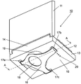
- FIG. 1A is a perspective view of a notebook computer, which is an information processing apparatus according to a first embodiment of the present invention, viewed from the lower back side.
- FIG. 1B is a cross-sectional view taken along the line AA, which is a line parallel to the longitudinal direction of the rear case 13 of FIG. 1A.
- FIG. 2 is a perspective view showing a state in which the notebook computer, which is the information processing apparatus in the first embodiment of the present invention, is held by one hand.
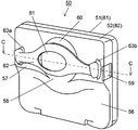
- FIG. 3A is a perspective view showing a state in which the notebook computer of the information processing apparatus in the second embodiment of the present invention is held with one hand.
- FIG. 3B is a cross-sectional view taken along the line BB, which is a line parallel to the longitudinal direction of the rear case portion of FIG. 3A.
- FIG. 4 is a perspective view of an information processing apparatus according to a third embodiment of the present invention as viewed from the front side.
- FIG. 5 is a perspective view of the information processing apparatus as viewed from the back side.
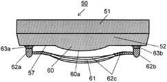
- 6 is a cross-sectional view taken along the line CC of FIG.
- FIG. 7 is a perspective view showing another example of the information processing apparatus.
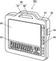
- FIG. 8 is a perspective view of an information processing apparatus according to a fourth embodiment of the present invention as viewed from the front side.
- FIG. 9 is a perspective view showing another example of the information processing apparatus.
- FIG. 1A is a perspective view of a notebook computer as an information processing apparatus according to Embodiment 1 of the present invention as viewed from the lower rear side, and FIG. 1B is a line parallel to the longitudinal direction of the rear case 13 of FIG. 1A. 1 is a cross-sectional view taken along the line AA.
- the notebook computer main body 10 has a front case 11 on which a display unit such as a liquid crystal display (not shown) as a display unit is arranged, an input device such as a keyboard 12 facing the front case 11 and a CPU or HDD And the like, and is constituted by a rear case 13 containing the same.
- the rear case 13 and the front case 11 are configured to be foldable by the hinges 14.
- FIG. 1A shows a state in which the front housing unit 11 is opened so that a display device disposed in the front housing unit 11 can be seen visually.
- a belt (hereinafter referred to as a hand strap) 16 for supporting the notebook computer main body 10 is provided on the back surface portion 15 of the back surface housing portion 13.
- the hand strap 16 is a substantially T-shaped belt fixed to the back housing 13 at three points of the fixing portions 17a, 17b and 17c, and a substantially circular penetrating portion 18 is provided at a substantially central portion thereof.
- substantially T-shaped indicates that the fixing portion 17c is provided in a position parallel to the hinge portion 14 and perpendicular to the line connecting the fixing portion 17a and the fixing portion 17b.
- the back surface portion 15 is provided with a convex portion 19 having a substantially spherical shape, and the through portion 18 of the hand strap 16 is provided corresponding to the position of the top 19 a of the convex portion 19.
- the hand strap 16 is made of an elastic hard rubber or a resin such as polybutylene terephthalate or an elastic material such as an elastic material.
- the fixing portion position adjusting portion can be adapted to the size and arrangement of the user's hand, and can change the positions of the fixing portions 17a, 17b and 17c of the hand strap 16 and can remove the hand strap 16. 20 are provided.
- the pair of fixed ends 16a and 16b of the hand strap 16 engaged with the fixed parts 17a and 17b are formed to be thicker than the sliding part 16d sliding on the back of the hand of the operator.
- FIG. 2 is a perspective view showing a state in which the notebook computer main body 10 of the information processing apparatus according to the first embodiment of the present invention is held with one hand.
- the one hand 21 is inserted between the hand strap 16 and the back surface portion 15 of the notebook computer main body 10, and the palm of the one hand 21 holds the spherical shaped convex portion 19 so as to wrap and hold it.
- the third joint 22 such as the forefinger, the middle finger, or the ring finger of the one hand 21 protrudes from the penetrating portion 18. Therefore, the contact area between the convex portion 19 of the notebook computer body 10 and the palm of the one hand 21 and the contact area between the hand strap 16 and the back of the hand of the one hand 21 are increased by such a holding form.
- the close contact of the personal computer 10 can be made firm.
- the laptop personal computer 10 can be stably supported in a desired direction. Furthermore, the laptop computer 10 can be held without the need for extra power.
- the hand strap 16 is substantially T-shaped, and the notebook computer main body 10 can be held at an inclination angle of about 45 degrees with respect to the direction of the inserted one hand 21. Therefore, the notebook computer main body 10 can be made to face the operator while being held in one hand in a natural state, and operability such as key input can be improved without fatigue.
- the hand strap 16 is substantially T-shaped, fixed to the back surface portion 15 of the notebook computer main body 10 at three points, and provided with a substantially circular through portion 18 at a substantially central portion. Therefore, one hand can be positioned by inserting the one hand 21 for holding between the adjacent two fixing parts 17b and 17c. Furthermore, the outer peripheral portion of the penetrating portion 18 can be pressed against the back of the hand near the third joint 22 of the one hand 21 protruding from the penetrating portion 18 to limit the rotational freedom of the one hand.
- the hand strap 16 is made of an elastic material such as rubber or elastomer, it is possible to hold the notebook computer body 10 more firmly together with the one hand 21 which is held using its elastic force. Is possible.
- the hand strap 16 in a symmetrical T-shape, it can be used as a left-handed and right-handed person. Furthermore, by inserting one hand between the adjacent fixing portions 17b and 17c of the hand strap 16 having a substantially T shape, the direction of the notebook computer body 10 is inclined at about 45 degrees on the palm of the inserted one hand. The setting can be made, and the operator can improve the input operability and the visibility of the display device.
- the notebook computer 10 when the notebook computer 10 is used in a standing posture, etc., the notebook computer 10 can be held with one hand more firmly and without feeling of fatigue, so the notebook computer 10 is accidentally dropped. There is also less risk of causing problems, and operability and visibility can be improved.
- the pair of fixed ends 16a and 16b of the hand strap 16 it is preferable to configure the pair of fixed ends 16a and 16b of the hand strap 16 to be thicker than the thickness of the sliding portion 16d.
- the distance between the front end of the pair of fixed ends 16 a and 16 b and the back surface 15 may be equal to or greater than the distance between the most projecting top 19 a of the projection 19 and the back surface 15. That is, the sliding portion 16d of the hand strap 16 is an elastic body, and even if the fixed ends 16a and 16b are the same elastic body, the thickness is thickened to have rigidity. In this way, when the notebook computer main body 10 is placed on a flat desk and used, the back of the notebook computer main body 10, that is, the hinge portion 14 side in FIG.
- the keyboard 12 is more preferably inclined.
- the fixed ends 16a, 16b and 16c also play the role of foot rubber of the notebook computer main body 10, so that the shock when placing the notebook computer main body 10 on a flat surface can be further mitigated. it can.
- the heights of the fixing portion 17a and the fixing portion 17b from the back surface portion 15 are the same, and the height is higher than the height of the top portion 19a of the convex portion 19, and the fixing portions 17a and 17b
- the keyboard 12 can also be tilted by attaching a rigid resin or metal leg or the like. At this time, the keyboard 12 can be inclined by configuring the height of the fixing portion 17c from the back surface portion 15 lower than the heights of the fixing portions 17a and 17b.
- the fixing portions 17a and 17b are made of an elastic material, an effect as a foot rubber can be obtained as described above.
- the notebook computer main body 10 can be held with the palm and back of the hand 21 so that the finger can be used freely. Therefore, the holding stability of the notebook computer main body 10 is further improved by making the finger tips of the open hand of the one hand 21 to be held along the surface provided with the hinge portion 14 of the notebook computer main body 10 as shown in FIG. can do.
- the operability can be further improved.
- the notebook computer main body can be stably held with one hand, and operability and visibility such as key input operation with one hand can be improved. .
- FIGS. 3A and 3B are diagrams for explaining the second embodiment of the present invention
- FIG. 3A is a perspective view showing a state in which the notebook computer of the information processing apparatus in the second embodiment of the present invention is held with one hand.
- FIG. 3B is a cross-sectional view taken along the line BB, which is a line parallel to the longitudinal direction of the rear case portion of FIG. 3A.
- the same components as the components used in FIGS. 1A, 1B and 2 are denoted by the same reference numerals, and the description thereof is omitted.
- the basic configuration of the notebook computer main body 101 which is an information processing apparatus according to the present embodiment, is the same as that of the first embodiment, and as shown in FIG.
- a spherical convex 19 similar to that shown in FIG. 1B is provided.
- the configuration of the hand strap 30 is different from that of the first embodiment. That is, in the present embodiment, the hand strap 30 is a two-point fixing type belt, and has a substantially elliptical penetrating portion 31 corresponding to the top 19 a of the convex portion 19, and both ends thereof are provided on the back surface 15. It is fixed to the fixed parts 32a and 32b.
- the shape of the through portion 31 is not limited to an elliptical shape, and may be a shape or a size that allows the back of the hand 21 holding the notebook computer main body 101 to protrude.
- the positions and the length of the hand strap 30 can be adjusted so that the fixing portions 32a and 32b can be adjusted according to the size of the hand 21 of the user and the desired angle to be supported.
- the hand strap 30 is made of an elastic hard rubber, or a resin such as polybutylene terephthalate or an elastic resin such as an elastomeric material.
- the fixed ends 30a and 30b of the hand strap 30 engaged with the fixed parts 32a and 32b provided on the back face part 15 are thicker than the sliding part 30c sliding on the back of the hand of the operator. Further, the height from the back surface portion 15 to the tip end portions of the fixed ends 30 a and 30 b is configured to be larger than the height from the back surface portion 15 of the top portion 19 a of the convex portion 19.
- One hand 21 is inserted between the hand strap 30 and the back surface 15 of the notebook computer main body 101, and held along the outer periphery of the projection 19 so that the palm 19 of the hand 21 grips the projection 19.
- the notebook computer body 101 is held by projecting the third joint 22 of the index finger, the middle finger and the ring finger. With such a holding form, the contact area between the convex portion 19 of the notebook computer main body 101 and the palm of the one hand 21 and the contact area between the hand strap 30 and the back of the hand of the one hand 21 increase.
- the adhesion of 101 can be strengthened.
- the laptop computer body 101 can be stably supported in a desired direction, and no extra force is required. Can be held in
- the hand strap 30 is a two-point fixed type belt
- the occupied area of the belt is small, for example, a smaller portable information processing apparatus having a liquid crystal display size of 8.9 inches or the like or Adaptable to game machines etc.
- the hand strap 30 is in the form of a two-point fixed belt, the palm is pressed while being bent along the outer periphery of the convex portion 19, and the forefinger, middle finger and ring finger from the penetrating portion 31
- the bent third joint portion 22 is in a projecting state, and the notebook computer main body 101 can be firmly held. Therefore, when the notebook computer main body 101 is used in a standing posture, etc., the notebook computer main body 101 can be held more firmly with one hand 21, so the danger of causing the notebook computer main body 101 to fall by mistake etc. Sex also decreases.
- the sliding portion 30c of the hand strap 30 made of rubber, elastomer or the like is bent and the tip end of the fixed ends 30a and 30b abuts against the flat surface on the desk It can be done.
- the keyboard 12 can be placed on a desk in an inclined state to enhance the operability of key input, and the fixed ends 30a and 30b can also function as foot rubber as in the first embodiment. it can.
- the through portion 31 is provided in the hand strap 30 so that the third joint portion 22 of the one hand 21 enters the through portion 31. Therefore, even if the one hand 21 is held at an inclination angle of, for example, 45 degrees with respect to the notebook computer main body 101, it can be held stably. Therefore, it is possible to hold the notebook computer main body 101 with one hand in a natural state so as to face the operator, and to improve operability such as key input and visibility of the display.
- the notebook computer main body 101 can be held with the palm and the back of the hand, and the finger can be used freely. Therefore, the holding stability of the notebook computer main body 101 is achieved by keeping the fingertip of the open finger of the one hand to be held along the surface provided with the hinge portion 14 (see FIG. 1) of the notebook computer main body 101 as shown in FIG. 3A. Sex can be further improved. Further, even if a second auxiliary key having the same function as the auxiliary key on the keyboard 12 is provided at a position where it can be touched with a fingertip, the operability can be further improved.
- the information processing apparatus is described in which the front case unit 11 for arranging the display device and the rear case unit 13 for arranging the input device are pivotally supported by the hinge unit 14. .
- FIG. 4 is a perspective view of the information processing apparatus according to the third embodiment of the present invention as viewed from the front side
- FIG. 5 is a perspective view of the same information processing apparatus as viewed from the back side
- FIG. FIG. 4 is a perspective view of the information processing apparatus according to the third embodiment of the present invention as viewed from the front side
- FIG. 5 is a perspective view of the same information processing apparatus as viewed from the back side
- the information processing apparatus includes a display unit 53 as a display unit on the front side and an operation button 55.
- a portable navigation system hereinafter referred to as NAVI
- a personal digital assistant hereinafter referred to as a PDA
- a game console etc.
- NAVI will be described as an example.
- the NAVI 50 is composed of a front case 51 and a rear case 52 formed by molding a resin or the like.
- the front case unit 51 has a display unit 53 such as a liquid crystal display which is a display unit for displaying visual information and an operation as a control button for controlling visual information for selecting a menu on a display screen.
- a button 55 and the like are disposed, and all operations of the NAVI 50 are configured on the front side.
- the molded rear housing portion 52 has a substantially rectangular low surface portion 56 and a high surface portion 57 that is thicker than the low surface portion 56 connected to the low surface portion 56.
- the boundary between the low surface portion 56 and the high surface portion 57 is configured to have a step portion 58 with an inclined surface.
- a battery or the like as a power source of the NAVI 50 can be incorporated in the internal space of the thick high surface portion 57.
- the side surface of the rear case 52 has a lid 59 for battery replacement, For example, connection terminals with an external device such as USB are also provided as needed.
- a convex portion 60 having a spherical shape is provided substantially at the center of the high surface portion 57, and the convex portion 60 is configured such that a part of the bottom thereof crosses the step portion 58 and protrudes in the direction of the low surface portion 56 There is.
- a hand strap 62 having a penetrating portion 61 at a position covering the convex portion 60 and facing the top portion 60 a of the convex portion 60 is provided. Both ends of the hand strap 62 are fixed to the rear case 52 by fixing portions 63a and 63b.
- the fixing portions 63a and 63b can be adjusted in position, and the length of the hand strap 62 can be adjusted. Furthermore, as in the first embodiment and the second embodiment, the hand strap 62 is made of an elastic resin such as stretchable rubber, polybutylene terephthalate, or an elastomeric material.
- the fixed ends 62a and 62b of the hand strap 62 are formed thicker than the thickness of the sliding portion 62c on which the back of the hand of the hand strap 62 slides. Further, the heights of the fixed ends 62a and 62b from the high surface portion 57 are the same, and the heights of the top portion 60a of the convex portion 60 from the high surface portion 57 are set higher. In such a case, when the NAVI 50 is used by placing it on a flat desk, the sliding portion 62c of the hand strap 62 is elastically deformed with the mass of the NAVI 50 because the thickness is thinner than the fixed ends 62a and 62b. The moving part 62c is flattened.
- the fixed ends 62a and 62b are formed thicker than the sliding portion 62c and therefore have rigidity, and the height of the fixed ends 62a and 62b from the high surface portion 57 is the height of the top portion 60a of the convex portion 60. It is over the height. Therefore, the NAVI 50 can be inclined and stably mounted on a desk. Further, when the fixed ends 62a and 62b are inclined so as to be lower from the high surface portion 57 to the low surface portion 56 as shown in FIG. 5, the NAVI 50 is further inclined and stably mounted on a desk. Can. Therefore, when the NAVI 50 is placed on a desk, the display unit 53 can be inclined to enhance the visibility, and the operability of the operation button 55 can be enhanced.
- the fixed ends 62a and 62b When the fixed ends 62a and 62b are made of a material having the same elasticity as that of the sliding portion 62c, the fixed ends 62a and 62b exhibit the function as the foot rubber of the NAVI 50. That is, when the rear case 52 is placed on a flat surface such as a desk, or when the display unit 53 is touched, or when the operation button 55 is pressed, the impact applied to the NAVI 50 is alleviated. The operability can be further improved.
- the hand since the back of the hand corresponding to the convex portion 60 in one hand inserted between the hand strap 62 and the rear housing portion 52 can be projected from the penetrating portion 61, the hand is squeezed and, for example, occurrence of numbness and the like is alleviated. Ru.
- a frictional force is generated between the outline of the penetrating portion 61 and the back of the one hand exposed to the outside, and the frictional force can stably support the NAVI 50 in a desired direction. Furthermore, the NAVI 50 can be held without the need for extra power.
- the hand strap 62 is a two-point fixed type belt, the occupied area of the belt is small, and it is particularly applicable to a smaller NAVI or game machine.
- the hand strap 62 is a single belt shape, the palm is pressed while being bent along the outer periphery of the convex portion 60, and the third joint portion obtained by bending the forefinger, the middle finger or the ring finger from the penetrating portion 61 is Being in a state of protrusion, the risk of the NAVI 50 slipping is reduced. Therefore, when using the NAVI 50 in a standing posture, etc., the NAVI 50 can be held more firmly and stably with one hand, and the risk of dropping the NAVI 50 by mistake or the like is reduced.
- the NAVI 50 can be held with the palm and back of one hand, and the finger can be used freely. Therefore, the holding stability of the NAVI 50 can be further improved by making the fingertip of the open finger of one hand to be held, for example, along the upper end face of the rear case 52 similarly to FIG. 3A.
- an auxiliary button can be provided on the side portion or the like that can be touched with a fingertip, and the operability of the NAVI 50 can be further improved.
- the through portion 61 is provided in the hand strap 62 so that the third joint of one hand enters the through portion 61. Therefore, even if one hand is inclined at an arbitrary angle (for example, 45 degrees) with respect to the NAVI 50, it can be stably held.
- the NAVI 50 can be held in a natural state in which the operator faces the operator so that operability such as key input and visibility of the display unit 53 can be improved.
- the rear surface portion of the rear housing portion 52 is inclined at the boundary between the low surface portion 56 having a substantially rectangular shape, the high surface portion 57 connected to the low surface portion 56, the low surface portion 56 and the high surface portion 57 And the step portion 58 is provided. Furthermore, a portion of the bottom of the convex portion 60 provided on the high surface portion 57 crosses the step portion 58 and protrudes in the direction of the low surface portion 56. Therefore, when the inserted palm is bent along the convex portion 60, the low surface portion 56 can be shaped to extend from the third joint of the hand to the wrist, and the angle in the direction orthogonal to the palm to be held The degree of freedom can be improved to further reduce the feeling of fatigue.
- FIG. 7 is a perspective view showing another example of the NAVI 50 according to the embodiment of the present invention.
- the NAVI 501 shown in FIG. 7 is the same as the NAVI 50 shown in FIG. 4, but the NAVI 501 is provided with a handle 64 provided with a grip 66 via a space 65 at the top, that is, the top of the display 53.
- the handle 64 By providing the handle 64, it is convenient to carry the NAVI 501, shift from the state where the NAVI 501 is supported by the hand strap 62 to the state where the NAVI 501 is placed on a desk, and the like. Further, when the rear case 52 is held by one hand as described above, the finger of the held one hand can be inserted into the space 65 and held more stably.
- NAVI 50 and NAVI 501 in the present embodiment can be stably held by one hand inserted between the hand strap 62 and the rear case 52, and by the operation button 55 with the other hand.
- the operability of operation and the like and the visibility of the display unit 53 can be improved.
- FIG. 8 is a perspective view of a PDA 80 according to a fourth embodiment of the present invention as viewed from the front side
- FIG. 9 is a perspective view of a PDA 801 of another example of the PDA 80.
- PDAs 80 and 801 in the present embodiment have a display unit 83 as a display unit on the front side, and a keyboard 84 and operation buttons 85.
- the PDA 80 is composed of a front case 81 and a rear case 82 obtained by molding a resin or the like.
- a display unit 83 such as a liquid crystal display, a keyboard 84 having an input function, an operation button 85 for controlling visual information by selecting a menu on a display screen, and the like are arranged on the front case 81. Is configured to be able to perform all operations.
- a handle 86 is provided on the top of the PDA 80, that is, on the top of the display unit 83.
- the handle 86 has a grip 88 having a space 87.
- back case section 82 of PDA 80 in the present embodiment is the same as the configuration shown in FIGS. 5 and 6 described in the third embodiment, and the back case section using FIGS. 5 and 6 The configuration of 82 will be described.
- the rear surface portion of the rear housing portion 82 includes the substantially rectangular low surface portion 56, the high surface portion 57 connected to the low surface portion 56, and the step portion 58 at the boundary between the low surface portion 56 and the high surface portion 57.
- a battery as a power source of the PDA 80 can be incorporated in the internal space of the thick high surface portion 57.
- the side wall of the rear case 52 has a lid 89 for battery replacement, USB, or the like. And other connection terminals with external devices.
- a convex portion 60 having a spherical shape is provided substantially at the center of the high surface portion 57, and the convex portion 60 is configured such that a part of the bottom thereof crosses the step portion 58 and protrudes in the direction of the low surface portion 56 There is.
- a hand strap 62 having a through portion 61 at a position covering the convex portion 60 and facing the top of the convex portion 60 is provided. Both ends of the hand strap 62 are fixed to the rear case 52 by fixing portions 63a and 63b.
- the fixing portions 63a and 63b can be adjusted in position, and the length of the hand strap 62 can be adjusted. Further, the hand strap 62 is made of elastic resin such as stretchable rubber, polybutylene terephthalate, or a material having an elastomeric property.
- the fixed ends 62a and 62b of the hand strap 62 are respectively formed thicker than the thickness of the sliding portion 62c on which the back of the hand of the hand strap 62 slides, and the fixed ends 62a and 62b.
- the height from the upper surface portion 57 is made the same, and is made higher than the height from the upper surface portion 57 of the top 60 a of the convex portion 60.
- the sliding portion 62c of the hand strap 62 is elastically deformed by the mass of the PDA 80 because the thickness is smaller than the fixed ends 62a and 62b.
- the sliding portion 62c When the PDA 80 is placed on a flat surface, the sliding portion 62c is flattened.
- the fixed ends 62a and 62b are formed to be thicker than the sliding portion 62c and therefore have rigidity, and the height of the fixed ends 62a and 62b from the high surface portion 57 is the height of the top 60a of the convex portion 60. Because it is higher than the height, the PDA 80 can be inclined and stably placed on the desk. Therefore, the display unit 83 can be inclined to improve the visibility, and the operability of the keyboard 84 and the operation button 85 can be improved.
- the fixed ends 62a and 62b exhibit the function as the foot rubber of the PDA 80, and when the PDA 80 is placed on a desk, when the display unit 83 is touched, the keyboard 84 or the operation is performed.
- pressing the button 85 or the like it is possible to absorb an impact such as a placement operation and / or an operation operation to improve stability and / or operability.
- the hand is squeezed and, for example, occurrence of numbness and the like is alleviated.
- a friction force is generated between the outline of the penetrating portion 61 and the back of the hand of the one hand exposed to the outside, and this friction force can stably support the PDA 80 in a desired direction, and also an extra force.
- the PDA 80 can be held without the need.
- the hand strap 62 is a two-point fixed type belt, the occupied area of the belt is small, and it can be particularly applied to a smaller PDA, a game machine, or the like.
- the hand strap 62 is simply in the form of a single belt.
- the palm is pressed while being bent along the outer periphery of the convex portion 60, and the forefinger, the middle finger and the ring finger are bent from the penetrating portion 61
- the three joints are in a projecting state, and the risk of the PDA 80 slipping is reduced. Therefore, in the case where the PDA 80 is used in the standing posture, the PDA 80 can be held more firmly and stably with one hand, so that the risk of accidentally dropping the PDA 80 is reduced.
- the PDA 80 can be held with the palm and back of one hand, and the finger can be used freely. Therefore, the holding stability of the PDA 80 can be further improved by making the fingertip of the open finger of one hand to be held, for example, along the upper end face of the rear case 52 as in FIG. 3A. By providing an auxiliary button that can be touched, the operability of the PDA 80 can be further improved.
- the through portion 61 is provided in the hand strap 62 so that the third joint of one hand enters the through portion 61. Therefore, even if one hand is inclined at an arbitrary angle (for example, 45 degrees) with respect to the PDA 80, it can be stably held, and the PDA 80 is held in a natural state facing the operator and key input And the like, and the visibility of the display unit 83 can be improved.
- an arbitrary angle for example, 45 degrees
- the rear surface portion of the rear housing portion 52 is inclined at the boundary between the low surface portion 56 having a substantially rectangular shape, the high surface portion 57 connected to the low surface portion 56, the low surface portion 56 and the high surface portion 57
- a step portion 58 is provided on the surface, and a part of the bottom of the convex portion 60 crosses the step portion 58 and protrudes in the direction of the low surface portion 56. Therefore, when the inserted palm of one hand is bent along the convex portion 60, the low surface portion 56 can be made to run from the third joint of the hand to the wrist. Therefore, the degree of freedom of the angle in the direction orthogonal to the palm to be held can be improved, and the feeling of fatigue can be further reduced.
- the PDA 80 which is the information processing apparatus in the present embodiment, it can be stably held by one hand inserted between the hand strap 62 and the rear case 82, and the operation by the other one hand is also possible.
- the operability such as the operation of the button 85 and the visibility of the display unit 83 can be improved.
- the display unit 83 and the keyboard 84 can be viewed in a comfortable posture and operated.
- FIG. 9 is a perspective view showing another example of the PDA 80 in the fourth embodiment.
- the PDA 801 shown in FIG. 9 has the same basic configuration as the PDA 80 shown in FIG. 8, but the PDA 801 is provided with a handle 86 provided with a grip 88 via a space 87 at the top, ie, the top of the display 83. .
- the handle 86 By providing the handle 86, it is convenient to carry the PDA 801 or shift from a state in which the PDA 801 is supported by the hand strap 62 to a state in which the PDA 801 is placed on a desk. Further, when the rear case 82 is held by one hand as described above, the finger of the one hand to be held can be inserted into the space 87 and held more stably.
- the PDA 801 in the present embodiment can be stably held with one hand inserted between the hand strap 62 and the rear housing portion 82, and the input operation from the keyboard 84 with the other one hand or
- the operability of the operation button 85 can be stably enhanced, and the visibility of the display unit 83 can be improved.
- the present invention can be applied to a game machine, a portable terminal used for inventory management or nursing of a patient, and the like.
- the control unit is not limited to the control button, and can be applied to a touch panel in which the display surface is touched with a hand or the like.
- the information processing apparatus According to the information processing apparatus according to the present invention, it is possible to realize an information processing apparatus which is firmly and stably held with one hand and improves operability such as key input operation. It is useful.
Landscapes
- Engineering & Computer Science (AREA)
- Computer Hardware Design (AREA)
- Theoretical Computer Science (AREA)
- Physics & Mathematics (AREA)
- General Engineering & Computer Science (AREA)
- Human Computer Interaction (AREA)
- General Physics & Mathematics (AREA)
- Mathematical Physics (AREA)
- Casings For Electric Apparatus (AREA)
Abstract
A notebook-sized personal computer main body (10) is provided with a front case body (11), and a rear case body (13) wherein a keyboard (12) and the like are arranged. On a rear surface section (15) of the notebook-sized personal computer main body, a substantially spherical protruding section (19) is arranged, and furthermore, a hand strap (16) having a penetrating section (18) for covering the protruding section (19) is arranged. Thus, the notebook-sized personal computer main body (10) is surely held by one hand.
Description
本発明は、ノートパソコンのような携帯型の情報処理装置に関し、特に、情報処理装置を手で指示することで携帯性を向上させるベルト(吊り紐、ハンドストラップ等とも称され、以下総称してハンドストラップと呼ぶ)を備えた情報処理装置に関するものである。
The present invention relates to a portable information processing apparatus such as a notebook computer, and in particular, a belt (also referred to as a hanging cord, a hand strap, etc.) for improving portability by manually instructing the information processing apparatus. The present invention relates to an information processing apparatus provided with a hand strap.
近年、パーソナルコンピュータでもノートパソコンのような携帯性に優れた情報処理装置が普及し、より携帯性を向上するためにハンドストラップを装着した携帯型のノートパソコンなどが市販されている。
In recent years, an information processing apparatus having excellent portability, such as a notebook computer, is widely used as a personal computer, and a portable notebook computer equipped with a hand strap has been marketed in order to improve portability.
ノートパソコンはコンピュータ本体と入力装置としてのキーボードなどが収納された背面筐体部と、平面ディスプレイなどが収納された前面筐体部とをヒンジ部で結合し、前面筐体部を折り畳んで全体としてノート型としたものが一般的である。
In the notebook computer, a hinge is connected to the rear case unit containing the computer main unit and the keyboard as an input device and the front case unit containing the flat display etc. by folding the front case unit as a whole. A notebook type is generally used.
近年は、これらのノートパソコンの軽量化、小型化が進展し、使用者がノートパソコンを携帯しながら立ったまま操作する場面が多くなっている。このような場合には、ノートパソコンの筐体部の端部を片手で保持しながら、もう一方の片手でキーボードなどを操作することになる。しかしながら、この構成ではノートパソコンを保持する片手に負担が掛かると共に、キーボードなどの操作を行う際にノートパソコンの保持が不安定なため入力操作をし難かった。
In recent years, weight reduction and miniaturization of these notebook computers have progressed, and there are many cases where a user operates while standing while carrying the notebook computer. In such a case, while holding the end of the case unit of the notebook computer with one hand, the keyboard or the like is operated with the other hand. However, in this configuration, a load is placed on one hand holding the notebook computer, and when the keyboard is operated, the input operation is difficult because the holding of the notebook computer is unstable.
この課題は、ノートパソコンを片手でしっかり保持することで解決でき、背面筐体部の背面部にハンドストラップを設け、そのハンドストラップに片手を差し込んで保持を確実に行う例が開示されている(例えば、特許文献1、2参照)。
This problem can be solved by holding the notebook PC firmly with one hand, and an example is disclosed in which a hand strap is provided on the back surface of the rear case, and one hand is inserted in the hand strap to hold it securely (see See, for example, Patent Documents 1 and 2).
しかしながら、上記の特許文献1または特許文献2に記載の従来の構成では、ハンドストラップはその両端部をノートパソコンの背面筐体部に固定した単なる帯状のベルトであり、ノートパソコンを保持するための手の甲とハンドストラップとの接触面積が小さい。そのために、挿入した手によってノートパソコンをしっかりと保持することができずに、ノートパソコンが揺動したり滑り落ちたりする。また、キーボードのキーを押圧した場合にも不安定に揺動してキー入力が不確実になり易いといった課題を有していた。
However, in the conventional configuration described in Patent Document 1 or Patent Document 2 described above, the hand strap is a mere belt-like belt whose both ends are fixed to the rear case portion of the notebook computer, and for holding the notebook computer. The contact area between the back of the hand and the hand strap is small. As a result, the laptop can rock or slip off without the inserted hand holding the laptop firmly. In addition, when the key of the keyboard is pressed, it has a problem that it swings unstably and the key input tends to be uncertain.
また、片手でノートパソコンを保持し、他方の片手でノートパソコンのキーボードなどを操作する場合などには、キーボードへの入力操作やディスプレイの視認性から、保持する片手に対してノートパソコンを傾斜した状態で保持できる状態とすることが望ましい。しかしながら、特許文献1または特許文献2に記載の従来のハンドストラップの構成では、ノートパソコンに対して傾斜した状態で保持すると、ノートパソコンの保持が不安定になるといった課題を有していた。
特開2000-105630号公報
特開2007-102532号公報
In addition, when holding the notebook computer with one hand and operating the keyboard of the notebook computer with the other hand, etc., the notebook computer was inclined to the holding one hand from the input operation to the keyboard and the visibility of the display. It is desirable to be able to hold in the state. However, the conventional hand strap configuration described in Patent Document 1 or Patent Document 2 has a problem that holding the notebook computer in an inclined state makes the holding of the notebook computer unstable.
JP 2000-105630 A JP 2007-102532 A
本発明の情報処理装置は、背面筐体部と、背面筐体部と対向する前面筐体部と、背面筐体部の背面部に外部に突出して設けた凸部と、凸部を覆うように背面筐体部に固定したベルトとを備えている。
The information processing apparatus according to the present invention covers the rear case, the front case facing the rear case, a convex portion provided to the outside of the rear case to protrude to the rear, and the convex portion. And a belt fixed to the rear case portion.
このような構成により、片手を背面筐体部とベルトの間に挿入すると、挿入した片手のひらが凸部に沿うことで、ベルトの押圧力で挿入した片手は疲労感なく背面筐体部を固定することができ、ノートパソコンの保持を確実に行うことができる。
With such a configuration, when one hand is inserted between the back housing portion and the belt, the inserted palm follows the convex portion, and the one hand inserted by the pressing force of the belt does not feel fatigue and fixes the back housing portion. It is possible to hold the notebook computer securely.
10,101 ノートパソコン本体
11,51,81 前面筐体部
12,84 キーボード
13,52,82 背面筐体部
14 ヒンジ部
15 背面部
16,30,62 ベルト(ハンドストラップ)
16a,16b,16c,30a,30b,62a,62b 固定端
16d,30c,62c 摺動部
17a,17b,17c,32a,32b,63a,63b 固定部
18,31,61 貫通部
19,60 凸部
19a,60a 頂部
20 固定部位置調整部
21 片手
22 第3関節部
50,501 NAVI
53,83 ディスプレイ部
55,85 操作ボタン
56 低面部
57 高面部
58 段差部
59,89 蓋部
64,86 把手
65,87 空間部
66,88 握り部
80,801 PDA DESCRIPTION OF SYMBOLS 10, 101 Notebook PC main body 11, 51, 81 Front case part 12, 84 Keyboard 13, 52, 82 Back case part 14 Hinge part 15 Back part 16, 30, 62 Belt (hand strap)
16a, 16b, 16c, 30a, 30b, 62a, 62b Fixed end 16d, 30c, 62c Sliding portion 17a, 17b, 17c, 32a, 32b, 63a, 63b Fixing portion 18, 31, 61 Through portion 19, 60 Convex portion 19a, 60a top 20 fixed part position adjustment part 21 one hand 22 third joint part 50, 501 NAVI
53, 83 Display 55, 85 Operation button 56 Low surface 57 High surface 58 Stepped portion 59, 89 Lid 64, 86 Handle 65, 87 Space 66, 88 Grip 80, 801 PDA
11,51,81 前面筐体部
12,84 キーボード
13,52,82 背面筐体部
14 ヒンジ部
15 背面部
16,30,62 ベルト(ハンドストラップ)
16a,16b,16c,30a,30b,62a,62b 固定端
16d,30c,62c 摺動部
17a,17b,17c,32a,32b,63a,63b 固定部
18,31,61 貫通部
19,60 凸部
19a,60a 頂部
20 固定部位置調整部
21 片手
22 第3関節部
50,501 NAVI
53,83 ディスプレイ部
55,85 操作ボタン
56 低面部
57 高面部
58 段差部
59,89 蓋部
64,86 把手
65,87 空間部
66,88 握り部
80,801 PDA DESCRIPTION OF
16a, 16b, 16c, 30a, 30b, 62a, 62b Fixed
53, 83
以下、本発明の実施の形態について、図面を参照しながら説明する。
Hereinafter, embodiments of the present invention will be described with reference to the drawings.
(実施の形態1)
図1Aは本発明の実施の形態1における情報処理装置であるノートパソコンを下方の背面側から見た斜視図であり、図1Bは図1Aの背面筐体部13の長手方向に平行な線であるA-A線断面図である。ノートパソコン本体10は表示部である液晶ディスプレイ(不図示)などのディスプレイ装置が配置された前面筐体部11と、前面筐体部11に対向しキーボード12などの入力装置が配置されCPUやHDDなどを内蔵した背面筐体部13とにより構成されている。背面筐体部13と前面筐体部11とはヒンジ部14によって折り畳み可能に構成される。図1Aは前面筐体部11を、前面筐体部11に配置されたディスプレイ装置が視認可能なように開いた状態を示している。 Embodiment 1
FIG. 1A is a perspective view of a notebook computer as an information processing apparatus according to Embodiment 1 of the present invention as viewed from the lower rear side, and FIG. 1B is a line parallel to the longitudinal direction of therear case 13 of FIG. 1A. 1 is a cross-sectional view taken along the line AA. The notebook computer main body 10 has a front case 11 on which a display unit such as a liquid crystal display (not shown) as a display unit is arranged, an input device such as a keyboard 12 facing the front case 11 and a CPU or HDD And the like, and is constituted by a rear case 13 containing the same. The rear case 13 and the front case 11 are configured to be foldable by the hinges 14. FIG. 1A shows a state in which the front housing unit 11 is opened so that a display device disposed in the front housing unit 11 can be seen visually.
図1Aは本発明の実施の形態1における情報処理装置であるノートパソコンを下方の背面側から見た斜視図であり、図1Bは図1Aの背面筐体部13の長手方向に平行な線であるA-A線断面図である。ノートパソコン本体10は表示部である液晶ディスプレイ(不図示)などのディスプレイ装置が配置された前面筐体部11と、前面筐体部11に対向しキーボード12などの入力装置が配置されCPUやHDDなどを内蔵した背面筐体部13とにより構成されている。背面筐体部13と前面筐体部11とはヒンジ部14によって折り畳み可能に構成される。図1Aは前面筐体部11を、前面筐体部11に配置されたディスプレイ装置が視認可能なように開いた状態を示している。 Embodiment 1
FIG. 1A is a perspective view of a notebook computer as an information processing apparatus according to Embodiment 1 of the present invention as viewed from the lower rear side, and FIG. 1B is a line parallel to the longitudinal direction of the
一方、背面筐体部13の背面部15にはノートパソコン本体10を支持するベルト(以下、ハンドストラップと呼ぶ)16が設けられている。ハンドストラップ16は固定部17a、17b、17cの3点で背面筐体部13と固定された略T字形状のベルトであり、その略中央部に略円形の貫通部18を設けた構成としている。ここで、略T字形状とは、ヒンジ部14に平行で固定部17aと固定部17bとを結ぶ線分に垂直な位置に、固定部17cが設けられて構成されている状態を示している。
On the other hand, a belt (hereinafter referred to as a hand strap) 16 for supporting the notebook computer main body 10 is provided on the back surface portion 15 of the back surface housing portion 13. The hand strap 16 is a substantially T-shaped belt fixed to the back housing 13 at three points of the fixing portions 17a, 17b and 17c, and a substantially circular penetrating portion 18 is provided at a substantially central portion thereof. . Here, substantially T-shaped indicates that the fixing portion 17c is provided in a position parallel to the hinge portion 14 and perpendicular to the line connecting the fixing portion 17a and the fixing portion 17b. .
また、図1Bに示すように、背面部15には略球面形状の凸部19が設けられ、ハンドストラップ16の貫通部18が、その凸部19の頂部19aの位置に対応して設けられている。なお、ハンドストラップ16は、伸縮自在な硬質ゴムや、ポリブチレンテレフタレートやエラストマー性を有する素材などの弾性を備える樹脂などの素材によって構成されている。さらに、使用者の手の大きさや配置に対応でき、ハンドストラップ16の固定部17a、17b、17cの位置を可変したり、ハンドストラップ16を取り外したりすることができるように、固定部位置調整部20が設けられている。また、固定部17aおよび17bに係合するハンドストラップ16の一対の固定端16aおよび16bは、操作者の手の甲と摺動する摺動部16dよりも肉厚になるように形成されている。
Further, as shown in FIG. 1B, the back surface portion 15 is provided with a convex portion 19 having a substantially spherical shape, and the through portion 18 of the hand strap 16 is provided corresponding to the position of the top 19 a of the convex portion 19. There is. The hand strap 16 is made of an elastic hard rubber or a resin such as polybutylene terephthalate or an elastic material such as an elastic material. Further, the fixing portion position adjusting portion can be adapted to the size and arrangement of the user's hand, and can change the positions of the fixing portions 17a, 17b and 17c of the hand strap 16 and can remove the hand strap 16. 20 are provided. The pair of fixed ends 16a and 16b of the hand strap 16 engaged with the fixed parts 17a and 17b are formed to be thicker than the sliding part 16d sliding on the back of the hand of the operator.
次に、本実施の形態において、ノートパソコン本体10を片手で保持して使用する場合の保持方法について説明する。図2は本発明の実施の形態1における情報処理装置のノートパソコン本体10を片手で保持した状態を示す斜視図である。
Next, in the present embodiment, a method of holding and using the notebook computer main body 10 with one hand will be described. FIG. 2 is a perspective view showing a state in which the notebook computer main body 10 of the information processing apparatus according to the first embodiment of the present invention is held with one hand.
図2に示すように、ハンドストラップ16とノートパソコン本体10の背面部15との間に片手21を挿入し、片手21の手のひらで球面形状の凸部19を包み込んで握るように保持する。このとき、貫通部18から片手21の人差し指、中指あるいは薬指などの第3関節部22が突出した状態となる。したがって、このような保持形態により、ノートパソコン本体10の凸部19と片手21の手のひらとの接触面積、およびハンドストラップ16と片手21の手の甲との接触面積が増加することで、片手21に対するノートパソコン本体10の密着を強固にできる。さらに、ハンドストラップ16と背面部15との間に挿入した片手21の凸部19に対応する手の甲の一部は貫通部18から外側に突出できる。そのため、片手2が圧迫されてしびれなどを発生することが緩和される。また、貫通部18の輪郭と外側に露出する片手21の手の甲との間の摩擦力によりノートパソコン本体10を所望の方向に安定して支持することができる。さらに、余分な力を必要とせずにノートパソコン本体10を保持することができる。
As shown in FIG. 2, the one hand 21 is inserted between the hand strap 16 and the back surface portion 15 of the notebook computer main body 10, and the palm of the one hand 21 holds the spherical shaped convex portion 19 so as to wrap and hold it. At this time, the third joint 22 such as the forefinger, the middle finger, or the ring finger of the one hand 21 protrudes from the penetrating portion 18. Therefore, the contact area between the convex portion 19 of the notebook computer body 10 and the palm of the one hand 21 and the contact area between the hand strap 16 and the back of the hand of the one hand 21 are increased by such a holding form. The close contact of the personal computer 10 can be made firm. Furthermore, a part of the back of the hand corresponding to the convex portion 19 of the one hand 21 inserted between the hand strap 16 and the back surface portion 15 can project outward from the penetration portion 18. Therefore, it is relieved that the one hand 2 is compressed to cause numbness and the like. Further, due to the frictional force between the outline of the penetrating portion 18 and the back of the hand of the one hand 21 exposed to the outside, the laptop personal computer 10 can be stably supported in a desired direction. Furthermore, the laptop computer 10 can be held without the need for extra power.
さらに、本実施の形態ではハンドストラップ16を略T字形状としており、挿入した片手21の向きに対してノートパソコン本体10を45度程度の傾斜角度で保持することができる。そのため、ノートパソコン本体10を自然な状態で片手保持しながら操作者に対して正対させることができ、疲労感がない状態でキー入力などの操作性を向上させることができる。
Furthermore, in the present embodiment, the hand strap 16 is substantially T-shaped, and the notebook computer main body 10 can be held at an inclination angle of about 45 degrees with respect to the direction of the inserted one hand 21. Therefore, the notebook computer main body 10 can be made to face the operator while being held in one hand in a natural state, and operability such as key input can be improved without fatigue.
また、ハンドストラップ16を略T字形状とし、3点でノートパソコン本体10の背面部15に固定して、しかも略中央部に略円形の貫通部18を備えている。そのため、保持するための片手21を隣接する2点の固定部17b、17c間に挿入して片手の位置決めができる。さらに、貫通部18から突出した片手21の第3関節22近傍の手の甲に貫通部18の外周部を押し当てて片手の回転自由度を制限することもできる。また、ハンドストラップ16を伸縮自在なゴムやエラストマーなどの素材によって構成しているために、その弾性力を利用して保持する片手21と一体となってノートパソコン本体10をさらに強固に保持することが可能となる。さらに、ハンドストラップ16を左右対称なT字形状とすることで、左利き、右利き兼用にすることができる。さらに、略T字形状を有するハンドストラップ16の隣接する固定部17bと17c間に片手を挿入することにより、挿入した片手の手のひら上でノートパソコン本体10の向きは略45度程度の傾斜角度に設定でき、操作者が入力操作性およびディスプレイ装置の視認性を向上させることができる。
The hand strap 16 is substantially T-shaped, fixed to the back surface portion 15 of the notebook computer main body 10 at three points, and provided with a substantially circular through portion 18 at a substantially central portion. Therefore, one hand can be positioned by inserting the one hand 21 for holding between the adjacent two fixing parts 17b and 17c. Furthermore, the outer peripheral portion of the penetrating portion 18 can be pressed against the back of the hand near the third joint 22 of the one hand 21 protruding from the penetrating portion 18 to limit the rotational freedom of the one hand. In addition, since the hand strap 16 is made of an elastic material such as rubber or elastomer, it is possible to hold the notebook computer body 10 more firmly together with the one hand 21 which is held using its elastic force. Is possible. Furthermore, by forming the hand strap 16 in a symmetrical T-shape, it can be used as a left-handed and right-handed person. Furthermore, by inserting one hand between the adjacent fixing portions 17b and 17c of the hand strap 16 having a substantially T shape, the direction of the notebook computer body 10 is inclined at about 45 degrees on the palm of the inserted one hand. The setting can be made, and the operator can improve the input operability and the visibility of the display device.
したがって、ノートパソコン本体10を立った姿勢のままで使用する場合などには、片手でより強固に、さらに疲労感なくノートパソコン本体10を保持することができるため、ノートパソコン本体10を誤って落下させるなどの危険性も少なくなり、操作性および視認性を高めることができる。
Therefore, when the notebook computer 10 is used in a standing posture, etc., the notebook computer 10 can be held with one hand more firmly and without feeling of fatigue, so the notebook computer 10 is accidentally dropped. There is also less risk of causing problems, and operability and visibility can be improved.
また、図1Bに示すように、ハンドストラップ16の一対の固定端16aおよび16bを摺動部16dの厚みよりも肉厚に構成すれば好ましい。かつ、一対の固定端16aおよび16bの先端部と背面部15との距離を、凸部19の最も突出している頂部19aと背面部15との距離以上としてもよい。すなわち、ハンドストラップ16の摺動部16dが弾性体であり、固定端16a、16bが同じ弾性体でも肉厚を厚く構成して剛性を有するようにしている。このようにすると、ノートパソコン本体10を平坦な机上に置いて使用する場合には、ノートパソコン本体10の後部、すなわち、図1のヒンジ部14側が高くなってキーボード12を傾斜させることができる。この構成により、キー入力の際に加わる押圧力は固定端16aおよび16bにより吸収されるため、操作性を高めることができる。さらに、摺動部16dの弾性によりノートパソコン本体10を机上に載置する際の衝撃を吸収することができる。
Further, as shown in FIG. 1B, it is preferable to configure the pair of fixed ends 16a and 16b of the hand strap 16 to be thicker than the thickness of the sliding portion 16d. In addition, the distance between the front end of the pair of fixed ends 16 a and 16 b and the back surface 15 may be equal to or greater than the distance between the most projecting top 19 a of the projection 19 and the back surface 15. That is, the sliding portion 16d of the hand strap 16 is an elastic body, and even if the fixed ends 16a and 16b are the same elastic body, the thickness is thickened to have rigidity. In this way, when the notebook computer main body 10 is placed on a flat desk and used, the back of the notebook computer main body 10, that is, the hinge portion 14 side in FIG. 1 becomes high, and the keyboard 12 can be inclined. With this configuration, the pressing force applied at the time of key input is absorbed by the fixed ends 16a and 16b, so that the operability can be improved. Furthermore, due to the elasticity of the sliding portion 16d, it is possible to absorb an impact when placing the notebook computer main body 10 on a desk.
このとき、固定部17cと係合するハンドストラップ16の固定端16cは、例えば摺動部16dと同等の肉厚とすると、キーボード12の傾斜が確実になりより好ましい。このような構成によれば、固定端16a、16bおよび16cが、ノートパソコン本体10の足ゴムの役割も奏するため、ノートパソコン本体10を平坦面に載置する際の衝撃をより緩和することもできる。
At this time, if the fixed end 16c of the hand strap 16 engaged with the fixed portion 17c has, for example, a thickness equal to that of the sliding portion 16d, the keyboard 12 is more preferably inclined. According to such a configuration, the fixed ends 16a, 16b and 16c also play the role of foot rubber of the notebook computer main body 10, so that the shock when placing the notebook computer main body 10 on a flat surface can be further mitigated. it can.
なお、固定部17aと固定部17bの背面部15からの高さを同一とし、その高さを凸部19の頂部19aの高さよりも高い構成とし、固定部17a、17bに、ハンドストラップ16よりも剛性の高い樹脂製や金属製の脚などを取り付けることでも、キーボード12を傾斜させることができる。このとき、固定部17cの背面部15からの高さを、固定部17aおよび17bの高さよりも低く構成することで、キーボード12を傾斜させることができる。なお、固定部17aおよび17bを弾性材料で構成すると、上述と同様に足ゴムとしての効果が得ることができる。
The heights of the fixing portion 17a and the fixing portion 17b from the back surface portion 15 are the same, and the height is higher than the height of the top portion 19a of the convex portion 19, and the fixing portions 17a and 17b The keyboard 12 can also be tilted by attaching a rigid resin or metal leg or the like. At this time, the keyboard 12 can be inclined by configuring the height of the fixing portion 17c from the back surface portion 15 lower than the heights of the fixing portions 17a and 17b. When the fixing portions 17a and 17b are made of an elastic material, an effect as a foot rubber can be obtained as described above.
なお、本実施の形態における情報処理装置によれば、ノートパソコン本体10の保持を片手21の手のひらおよび手の甲で行うことができ、指部が自由に使える状態となる。そのため、保持する片手21の開放されている指の指先を、図2に示すようにノートパソコン本体10のヒンジ部14を備える面に沿わせることで、ノートパソコン本体10の保持安定性をより向上することができる。また指先で触れることができる位置に例えばキーボード12上の補助キーと同じ機能を有する第2の補助キーなどを設けることで、その操作性をさらに向上させることができる。
According to the information processing apparatus in the present embodiment, the notebook computer main body 10 can be held with the palm and back of the hand 21 so that the finger can be used freely. Therefore, the holding stability of the notebook computer main body 10 is further improved by making the finger tips of the open hand of the one hand 21 to be held along the surface provided with the hinge portion 14 of the notebook computer main body 10 as shown in FIG. can do. In addition, by providing a second auxiliary key or the like having the same function as the auxiliary key on the keyboard 12 at a position where it can be touched with a fingertip, for example, the operability can be further improved.
以上のように、本実施の形態における情報処理装置によれば、ノートパソコン本体を片手で安定して保持できるとともに、片手でのキー入力操作などの操作性と視認性とを向上させることができる。
As described above, according to the information processing apparatus in the present embodiment, the notebook computer main body can be stably held with one hand, and operability and visibility such as key input operation with one hand can be improved. .
(実施の形態2)
図3A、Bは本発明の実施の形態2を説明する図で、図3Aは本発明の実施の形態2における情報処理装置のノートパソコンを片手で保持した状態を示す斜視図であり、図3Bは図3Aの背面筐体部の長手方向に平行な線であるB-B線断面図である。図3A、Bにおいて、図1A、図1B,図2で用いた構成要素と同一の構成要素については同一の符号を付してその説明を省略する。 Second Embodiment
FIGS. 3A and 3B are diagrams for explaining the second embodiment of the present invention, and FIG. 3A is a perspective view showing a state in which the notebook computer of the information processing apparatus in the second embodiment of the present invention is held with one hand. FIG. 3B is a cross-sectional view taken along the line BB, which is a line parallel to the longitudinal direction of the rear case portion of FIG. 3A. In FIGS. 3A and 3B, the same components as the components used in FIGS. 1A, 1B and 2 are denoted by the same reference numerals, and the description thereof is omitted.
図3Aに示すように、本実施の形態における情報処理装置であるノートパソコン本体101の基本構成は実施の形態1と同様であり、図3Bに示すように、背面筐体部13の背面部15には図1Bと同様の球面形状の凸部19が設けられている。
As shown in FIG. 3A, the basic configuration of the notebook computer main body 101, which is an information processing apparatus according to the present embodiment, is the same as that of the first embodiment, and as shown in FIG. On the other hand, a spherical convex 19 similar to that shown in FIG. 1B is provided.
本実施の形態ではハンドストラップ30の構成が実施の形態1と異なる。すなわち、本実施の形態ではハンドストラップ30は2点固定式のベルトであって、凸部19の頂部19aに対応させて略楕円形の貫通部31を有し、その両端が背面部15に設けられた固定部32a、32bに固定されている。貫通部31の形状は楕円形に限らず、ノートパソコン本体101を保持する片手21の甲を突出させることができる形状や大きさであればよい。固定部32a、32bは使用者の片手21の大きさ、支持する好みの角度に応じて調節できるように、その位置やハンドストラップ30の長さが調整できる構成としている。また、実施の形態1と同様に、ハンドストラップ30は伸縮自在な硬質ゴムや、ポリブチレンテレフタレートやエラストマー性を有する素材などの弾性を備える樹脂などの素材によって構成されている。
In the present embodiment, the configuration of the hand strap 30 is different from that of the first embodiment. That is, in the present embodiment, the hand strap 30 is a two-point fixing type belt, and has a substantially elliptical penetrating portion 31 corresponding to the top 19 a of the convex portion 19, and both ends thereof are provided on the back surface 15. It is fixed to the fixed parts 32a and 32b. The shape of the through portion 31 is not limited to an elliptical shape, and may be a shape or a size that allows the back of the hand 21 holding the notebook computer main body 101 to protrude. The positions and the length of the hand strap 30 can be adjusted so that the fixing portions 32a and 32b can be adjusted according to the size of the hand 21 of the user and the desired angle to be supported. Further, as in the first embodiment, the hand strap 30 is made of an elastic hard rubber, or a resin such as polybutylene terephthalate or an elastic resin such as an elastomeric material.
また、背面部15に備える固定部32a、32bと係合するハンドストラップ30の固定端30a、30bは、操作者の手の甲と摺動する摺動部30cよりも肉厚に構成されている。また、背面部15から固定端30a、30bの先端部までの高さが、凸部19の頂部19aの背面部15からの高さより大きくなるように構成している。
The fixed ends 30a and 30b of the hand strap 30 engaged with the fixed parts 32a and 32b provided on the back face part 15 are thicker than the sliding part 30c sliding on the back of the hand of the operator. Further, the height from the back surface portion 15 to the tip end portions of the fixed ends 30 a and 30 b is configured to be larger than the height from the back surface portion 15 of the top portion 19 a of the convex portion 19.
次に、本実施の形態におけるノートパソコン本体101を片手で保持して使用する場合の保持方法について説明する。ハンドストラップ30とノートパソコン本体101の背面部15との間に片手21を挿入して、片手21の手のひらで凸部19を握るように凸部19の外周に沿って保持し、貫通部31に人差し指、中指および薬指の第3関節部22を突出させてノートパソコン本体101を保持する。このような保持形態により、ノートパソコン本体101の凸部19と片手21の手のひらとの接触面積、およびハンドストラップ30と片手21の手の甲との接触面積が増加することで、片手21に対するノートパソコン本体101の密着を強固にすることができる。さらに、ハンドストラップ30と背面部15との間に挿入した片手21の凸部19に対応する手の甲の一部を貫通部31から外側に突出できるため、手が圧迫されて例えばしびれなどが発生することが緩和される。また、貫通部31の輪郭と外側に露出する片手21の手の甲との間の摩擦力によりノートパソコン本体101を所望の方向に安定して支持することができ、なおかつ、余分な力を必要とせずに保持することができる。
Next, a method of holding and using the notebook computer main body 101 according to the present embodiment with one hand will be described. One hand 21 is inserted between the hand strap 30 and the back surface 15 of the notebook computer main body 101, and held along the outer periphery of the projection 19 so that the palm 19 of the hand 21 grips the projection 19. The notebook computer body 101 is held by projecting the third joint 22 of the index finger, the middle finger and the ring finger. With such a holding form, the contact area between the convex portion 19 of the notebook computer main body 101 and the palm of the one hand 21 and the contact area between the hand strap 30 and the back of the hand of the one hand 21 increase. The adhesion of 101 can be strengthened. Furthermore, since a part of the back of the hand corresponding to the convex portion 19 of the one hand 21 inserted between the hand strap 30 and the back surface portion 15 can be projected outward from the penetrating portion 31, the hand is compressed and, for example, numbness occurs It is relieved. Also, due to the frictional force between the outline of the penetrating portion 31 and the back of the hand of the one hand 21 exposed to the outside, the laptop computer body 101 can be stably supported in a desired direction, and no extra force is required. Can be held in
また、本実施の形態では、ハンドストラップ30が2点固定式のベルトであるために、ベルトの占有面積が小さく、例えば液晶ディスプレイサイズが8.9インチ等のより小型の携帯型情報処理装置やゲーム機等に適応可能である。
Further, in the present embodiment, since the hand strap 30 is a two-point fixed type belt, the occupied area of the belt is small, for example, a smaller portable information processing apparatus having a liquid crystal display size of 8.9 inches or the like or Adaptable to game machines etc.
なお、本実施の形態では、ハンドストラップ30が2点固定式のベルト状であっても、手のひらを凸部19の外周に沿って折り曲げながら押圧するとともに、貫通部31から人差し指、中指および薬指を折り曲げた第3関節部22が突出した状態になり、ノートパソコン本体101をしっかりと保持することができる。したがって、ノートパソコン本体101を立った姿勢のままで使用する場合などには、片手21でより強固にノートパソコン本体101を保持することができるため、ノートパソコン本体101を誤って落下させるなどの危険性も少なくなる。
In the present embodiment, even if the hand strap 30 is in the form of a two-point fixed belt, the palm is pressed while being bent along the outer periphery of the convex portion 19, and the forefinger, middle finger and ring finger from the penetrating portion 31 The bent third joint portion 22 is in a projecting state, and the notebook computer main body 101 can be firmly held. Therefore, when the notebook computer main body 101 is used in a standing posture, etc., the notebook computer main body 101 can be held more firmly with one hand 21, so the danger of causing the notebook computer main body 101 to fall by mistake etc. Sex also decreases.
また、ノートパソコン本体101を平坦な机上に置いて使用する場合、ゴムやエラストマーなどからなるハンドストラップ30の摺動部30cが撓み、固定端30a、30bの先端部を机上の平坦面に当接させることができる。その結果、キーボード12を傾斜させた状態で机上に載置してキー入力の操作性を高めることができるととともに、実施形態1と同様に、固定端30a、30bが足ゴムとしての機能も実現できる。
In addition, when the notebook computer main body 101 is placed on a flat desk and used, the sliding portion 30c of the hand strap 30 made of rubber, elastomer or the like is bent and the tip end of the fixed ends 30a and 30b abuts against the flat surface on the desk It can be done. As a result, the keyboard 12 can be placed on a desk in an inclined state to enhance the operability of key input, and the fixed ends 30a and 30b can also function as foot rubber as in the first embodiment. it can.
さらに、本発明の実施の形態2ではハンドストラップ30に貫通部31を設けて片手21の第3関節部22が貫通部31に入り込むようにしている。そのため、片手21をノートパソコン本体101に対して例えば45度程度の傾斜角度で保持しても安定に保持することができる。そのため、ノートパソコン本体101を操作者に対して正対するように自然な状態で片手保持し、キー入力などの操作性やディスプレイの視認性を向上させることができる。
Furthermore, in the second embodiment of the present invention, the through portion 31 is provided in the hand strap 30 so that the third joint portion 22 of the one hand 21 enters the through portion 31. Therefore, even if the one hand 21 is held at an inclination angle of, for example, 45 degrees with respect to the notebook computer main body 101, it can be held stably. Therefore, it is possible to hold the notebook computer main body 101 with one hand in a natural state so as to face the operator, and to improve operability such as key input and visibility of the display.
なお、本実施の形態における情報処理装置によれば、ノートパソコン本体101の保持を、手のひらおよび手の甲で行うことができ、指部が自由に使える状態となる。そのため、保持する片手の開放されている指の指先を、図3Aに示すようにノートパソコン本体101のヒンジ部14(図1参照)を備える面に沿わせることで、ノートパソコン本体101の保持安定性をより向上することができる。また指先で触れることができる位置にキーボード12上の補助キーと同じ機能を有する第2の補助キーを設けても、その操作性をさらに向上させることができる。
Note that according to the information processing apparatus in the present embodiment, the notebook computer main body 101 can be held with the palm and the back of the hand, and the finger can be used freely. Therefore, the holding stability of the notebook computer main body 101 is achieved by keeping the fingertip of the open finger of the one hand to be held along the surface provided with the hinge portion 14 (see FIG. 1) of the notebook computer main body 101 as shown in FIG. 3A. Sex can be further improved. Further, even if a second auxiliary key having the same function as the auxiliary key on the keyboard 12 is provided at a position where it can be touched with a fingertip, the operability can be further improved.
(実施の形態3)
実施の形態1および2では、ディスプレイ装置を配する前面筐体部11と入力装置を配する背面筐体部13とがヒンジ部14で回動自在に軸支されている情報処理装置について説明した。次にディスプレイ装置と入力装置とが同一筐体に収納される情報処理装置に関する実施の形態について説明する。図4は本発明の実施の形態3における情報処理装置を前面側から見た斜視図であり、図5は同情報処理装置を背面側から見た斜視図、図6は図5におけるC-C線断面図である。 Third Embodiment
In the first and second embodiments, the information processing apparatus is described in which thefront case unit 11 for arranging the display device and the rear case unit 13 for arranging the input device are pivotally supported by the hinge unit 14. . Next, an embodiment of the information processing apparatus in which the display device and the input device are housed in the same housing will be described. 4 is a perspective view of the information processing apparatus according to the third embodiment of the present invention as viewed from the front side, FIG. 5 is a perspective view of the same information processing apparatus as viewed from the back side, and FIG. FIG.
実施の形態1および2では、ディスプレイ装置を配する前面筐体部11と入力装置を配する背面筐体部13とがヒンジ部14で回動自在に軸支されている情報処理装置について説明した。次にディスプレイ装置と入力装置とが同一筐体に収納される情報処理装置に関する実施の形態について説明する。図4は本発明の実施の形態3における情報処理装置を前面側から見た斜視図であり、図5は同情報処理装置を背面側から見た斜視図、図6は図5におけるC-C線断面図である。 Third Embodiment
In the first and second embodiments, the information processing apparatus is described in which the
図4、図5、図6に示すように、本実施の形態における情報処理装置は前面側に表示部としてのディスプレイ部53と、操作ボタン55とを備え、例えば携帯型ナビゲーションシステム(以下、NAVIと称す)、パーソナルディジタルアシスタント(以下、PDAと称す)、ゲーム機などである。本実施の形態ではNAVIを例に挙げ説明する。NAVI50は、樹脂などを成型加工した前面筐体部51と背面筐体部52とにより構成されている。図4に示すように、前面筐体部51には視認情報を表示する表示部である液晶ディスプレイなどのディスプレイ部53と、表示画面のメニュー選択などをする視認情報を制御する制御ボタンである操作ボタン55などが配置され、前面側でNAVI50の全ての操作が可能なように構成されている。
As shown in FIGS. 4, 5 and 6, the information processing apparatus according to the present embodiment includes a display unit 53 as a display unit on the front side and an operation button 55. For example, a portable navigation system (hereinafter referred to as NAVI) , A personal digital assistant (hereinafter referred to as a PDA), a game console, etc. In the present embodiment, NAVI will be described as an example. The NAVI 50 is composed of a front case 51 and a rear case 52 formed by molding a resin or the like. As shown in FIG. 4, the front case unit 51 has a display unit 53 such as a liquid crystal display which is a display unit for displaying visual information and an operation as a control button for controlling visual information for selecting a menu on a display screen. A button 55 and the like are disposed, and all operations of the NAVI 50 are configured on the front side.
また、図5に示すように、成型加工された背面筐体部52は、略矩形形状の低面部56と、低面部56に連設した低面部56よりも厚みの大きい高面部57とを有し、低面部56と高面部57との境界は傾斜面の段差部58を有するように構成されている。また、厚みの大きい高面部57の内部空間には、NAVI50の例えば電源としての電池などを内蔵することができ、この場合、背面筐体部52の側面には電池交換用の蓋部59や、例えばUSBなどの外部機器との接続端子なども必要に応じて設けている。さらに、高面部57の略中央部には球面形状の凸部60が設けられ、凸部60はその裾の一部が段差部58を横断し低面部56の方向に突出するように構成されている。
Further, as shown in FIG. 5, the molded rear housing portion 52 has a substantially rectangular low surface portion 56 and a high surface portion 57 that is thicker than the low surface portion 56 connected to the low surface portion 56. The boundary between the low surface portion 56 and the high surface portion 57 is configured to have a step portion 58 with an inclined surface. Further, a battery or the like as a power source of the NAVI 50 can be incorporated in the internal space of the thick high surface portion 57. In this case, the side surface of the rear case 52 has a lid 59 for battery replacement, For example, connection terminals with an external device such as USB are also provided as needed. Further, a convex portion 60 having a spherical shape is provided substantially at the center of the high surface portion 57, and the convex portion 60 is configured such that a part of the bottom thereof crosses the step portion 58 and protrudes in the direction of the low surface portion 56 There is.
さらに、凸部60を覆い凸部60の頂部60aと対向する位置に貫通部61を有するハンドストラップ62が設けられている。ハンドストラップ62の両端部は、固定部63a、63bによって背面筐体部52に固定されている。
Furthermore, a hand strap 62 having a penetrating portion 61 at a position covering the convex portion 60 and facing the top portion 60 a of the convex portion 60 is provided. Both ends of the hand strap 62 are fixed to the rear case 52 by fixing portions 63a and 63b.
また、固定部63a、63bはその位置調整が可能でハンドストラップ62の長さが調整可能なように構成されている。さらに、実施の形態1、実施の形態2と同様に、ハンドストラップ62は伸縮自在なゴムやポリブチレンテレフタレートやエラストマー性を有する素材などの弾性を備える樹脂などで構成されている。
The fixing portions 63a and 63b can be adjusted in position, and the length of the hand strap 62 can be adjusted. Furthermore, as in the first embodiment and the second embodiment, the hand strap 62 is made of an elastic resin such as stretchable rubber, polybutylene terephthalate, or an elastomeric material.
さらに、図6に示すように、例えばハンドストラップ62の固定端62a、62bをそれぞれハンドストラップ62の手の甲が摺動する摺動部62cの肉厚よりも厚く成形している。また、固定端62a、62bの高面部57からの高さを同一として、凸部60の頂部60aの高面部57からの高さよりも高くしている。このような場合には、NAVI50を平坦な机上に置いて使用する場合、ハンドストラップ62の摺動部62cは固定端62a、62bに比べて肉厚が薄いためNAVI50の質量で弾性変形し、摺動部62cは平坦化される。一方、固定端62a、62bは摺動部62cよりも厚肉で成形されているため剛性を有し、なおかつ、固定端62a、62bの高面部57からの高さが凸部60の頂部60aの高さ以上である。そのため、NAVI50を傾斜して机上に安定して載置することができる。また、固定端62aおよび62bを、図5に示したように高面部57から低面部56にかけて低くなるような傾斜を持たせると、さらに、NAVI50を傾斜して机上に安定して載置することができる。したがって、NAVI50を机上に載置した場合には、ディスプレイ部53が傾斜して視認性を高め、操作ボタン55の操作性を高めることができる。
Furthermore, as shown in FIG. 6, for example, the fixed ends 62a and 62b of the hand strap 62 are formed thicker than the thickness of the sliding portion 62c on which the back of the hand of the hand strap 62 slides. Further, the heights of the fixed ends 62a and 62b from the high surface portion 57 are the same, and the heights of the top portion 60a of the convex portion 60 from the high surface portion 57 are set higher. In such a case, when the NAVI 50 is used by placing it on a flat desk, the sliding portion 62c of the hand strap 62 is elastically deformed with the mass of the NAVI 50 because the thickness is thinner than the fixed ends 62a and 62b. The moving part 62c is flattened. On the other hand, the fixed ends 62a and 62b are formed thicker than the sliding portion 62c and therefore have rigidity, and the height of the fixed ends 62a and 62b from the high surface portion 57 is the height of the top portion 60a of the convex portion 60. It is over the height. Therefore, the NAVI 50 can be inclined and stably mounted on a desk. Further, when the fixed ends 62a and 62b are inclined so as to be lower from the high surface portion 57 to the low surface portion 56 as shown in FIG. 5, the NAVI 50 is further inclined and stably mounted on a desk. Can. Therefore, when the NAVI 50 is placed on a desk, the display unit 53 can be inclined to enhance the visibility, and the operability of the operation button 55 can be enhanced.
なお、固定端62aおよび62bを摺動部62cと同様の弾性を有する素材で構成すると、固定端62a、62bがNAVI50の足ゴムとしての機能を発揮する。すなわち、机上などの平坦な面に背面筐体部52を載置する際や、ディスプレイ部53に接触操作する際や、操作ボタン55を押下する際等にNAVI50に印加される衝撃を緩和して操作性をさらに向上させることができる。
When the fixed ends 62a and 62b are made of a material having the same elasticity as that of the sliding portion 62c, the fixed ends 62a and 62b exhibit the function as the foot rubber of the NAVI 50. That is, when the rear case 52 is placed on a flat surface such as a desk, or when the display unit 53 is touched, or when the operation button 55 is pressed, the impact applied to the NAVI 50 is alleviated. The operability can be further improved.
次に、本実施の形態におけるNAVI50を片手で保持して使用する場合の保持方法について説明する。ハンドストラップ62とNAVI50の背面筐体部52との間に片手を挿入し、片手のひらで凸部60の外周に沿って握るように、かつ、人差し指、中指および薬指の第3関節部を貫通部61から突出させるようにしてNAVI50を保持する。このような保持形態によりNAVI50の凸部60とNAVI50を支持する片手(図3A参照)の手のひらとの接触面積、およびハンドストラップ62と片手の手の甲との接触面積が増大する。そのため、支持する片手に対するNAVI50の密着を強固にすることができる。さらに、ハンドストラップ62と背面筐体部52との間に挿入した片手における凸部60に対応する手の甲を貫通部61から突出できるため、手が圧迫されて例えばしびれなどが発生することが緩和される。また、貫通部61の輪郭と外側に露出する片手の手の甲との間に摩擦力が生じ、この摩擦力によりNAVI50を所望の方向に安定して支持することができる。なおかつ、余分な力を必要とせずにNAVI50を保持することができる。
Next, a holding method in the case where the NAVI 50 in the present embodiment is held and used with one hand will be described. Insert one hand between the hand strap 62 and the rear case 52 of the NAVI 50 and hold it along the outer circumference of the protrusion 60 with one palm, and pass through the third joint of the index finger, middle finger and ring finger Hold the NAVI 50 as it protrudes from 61. Such a holding form increases the contact area between the projection 60 of the NAVI 50 and the palm of one hand (see FIG. 3A) supporting the NAVI 50 and the contact area between the hand strap 62 and the back of the one hand. Therefore, the adhesion of the NAVI 50 to the supported one hand can be strengthened. Furthermore, since the back of the hand corresponding to the convex portion 60 in one hand inserted between the hand strap 62 and the rear housing portion 52 can be projected from the penetrating portion 61, the hand is squeezed and, for example, occurrence of numbness and the like is alleviated. Ru. In addition, a frictional force is generated between the outline of the penetrating portion 61 and the back of the one hand exposed to the outside, and the frictional force can stably support the NAVI 50 in a desired direction. Furthermore, the NAVI 50 can be held without the need for extra power.
本実施の形態では、ハンドストラップ62が2点固定式のベルトであるために、ベルトの占有面積が小さく、より小型のNAVIやゲーム機などに特に適応可能である。
In the present embodiment, since the hand strap 62 is a two-point fixed type belt, the occupied area of the belt is small, and it is particularly applicable to a smaller NAVI or game machine.
なお、ハンドストラップ62が単に一本のベルト状であっても、手のひらを凸部60の外周に沿って折り曲げながら押圧するとともに、貫通部61から人差し指、中指あるいは薬指を折り曲げた第3関節部が突出した状態になり、NAVI50が滑り落ちる危険性が少なくなる。したがって、NAVI50を立った姿勢のままで使用する場合などには、片手でより強固かつ安定にNAVI50を保持することができ、NAVI50を誤って落下させるなどの危険性も少なくなる。
In addition, even if the hand strap 62 is a single belt shape, the palm is pressed while being bent along the outer periphery of the convex portion 60, and the third joint portion obtained by bending the forefinger, the middle finger or the ring finger from the penetrating portion 61 is Being in a state of protrusion, the risk of the NAVI 50 slipping is reduced. Therefore, when using the NAVI 50 in a standing posture, etc., the NAVI 50 can be held more firmly and stably with one hand, and the risk of dropping the NAVI 50 by mistake or the like is reduced.
また、NAVI50の保持を、片手の手のひらおよび手の甲で行うことができ、指部が自由に使える状態となる。そのため、保持する片手の開放されている指の指先を、例えば図3Aと同様に背面筐体52の上側端面に沿わせることで、NAVI50の保持安定性をより向上することができる。また指先で触れることができる側面部などに補助ボタンを設け、さらにNAVI50の操作性をさらに向上させることができる。
In addition, the NAVI 50 can be held with the palm and back of one hand, and the finger can be used freely. Therefore, the holding stability of the NAVI 50 can be further improved by making the fingertip of the open finger of one hand to be held, for example, along the upper end face of the rear case 52 similarly to FIG. 3A. In addition, an auxiliary button can be provided on the side portion or the like that can be touched with a fingertip, and the operability of the NAVI 50 can be further improved.
さらに、本実施の形態ではハンドストラップ62に貫通部61を設けて片手の第3関節部が貫通部61に入り込むようにしている。そのため、片手をNAVI50に対して任意の角度(例えば45度)で傾斜させても安定して保持することができる。また、NAVI50を操作者に対して正対させた自然な状態で保持してキー入力などの操作性およびディスプレイ部53の視認性を向上させることができる。
Furthermore, in the present embodiment, the through portion 61 is provided in the hand strap 62 so that the third joint of one hand enters the through portion 61. Therefore, even if one hand is inclined at an arbitrary angle (for example, 45 degrees) with respect to the NAVI 50, it can be stably held. In addition, the NAVI 50 can be held in a natural state in which the operator faces the operator so that operability such as key input and visibility of the display unit 53 can be improved.
また、本実施の形態では、背面筐体部52の背面部が、略矩形形状の低面部56と、低面部56に連設する高面部57と、低面部56および高面部57の境界に傾斜面で段差部58とを備える。さらに高面部57上に設けた凸部60の裾の一部が段差部58を横断し低面部56の方向に突出した構成としている。そのために、挿入した片手のひらを凸部60に沿って折り曲げる際に、低面部56に手の第3関節から手首まで沿わせる形状とすることができ、保持する手のひらに対して直交する方向の角度の自由度を向上させ疲労感をなお一層低減することができる。
Further, in the present embodiment, the rear surface portion of the rear housing portion 52 is inclined at the boundary between the low surface portion 56 having a substantially rectangular shape, the high surface portion 57 connected to the low surface portion 56, the low surface portion 56 and the high surface portion 57 And the step portion 58 is provided. Furthermore, a portion of the bottom of the convex portion 60 provided on the high surface portion 57 crosses the step portion 58 and protrudes in the direction of the low surface portion 56. Therefore, when the inserted palm is bent along the convex portion 60, the low surface portion 56 can be shaped to extend from the third joint of the hand to the wrist, and the angle in the direction orthogonal to the palm to be held The degree of freedom can be improved to further reduce the feeling of fatigue.
図7は本発明の実施の形態におけるNAVI50の他の例を示す斜視図である。図7に示すNAVI501は図4に示すNAVI50と同じであるが、NAVI501は、上部、すなわちディスプレイ部53の上部に、空間部65を介して握り部66を備える把手64を設けている。把手64を設けることによってNAVI501の持ち運びや、ハンドストラップ62によるNAVI501を支持する状態からNAVI501を机上に載置する状態への移行等が便利になるものである。また、前述のように背面筐体部52を片手で保持した際に、保持した片手の指部を空間部65に挿入してさらに安定して保持することが可能となる。
FIG. 7 is a perspective view showing another example of the NAVI 50 according to the embodiment of the present invention. The NAVI 501 shown in FIG. 7 is the same as the NAVI 50 shown in FIG. 4, but the NAVI 501 is provided with a handle 64 provided with a grip 66 via a space 65 at the top, that is, the top of the display 53. By providing the handle 64, it is convenient to carry the NAVI 501, shift from the state where the NAVI 501 is supported by the hand strap 62 to the state where the NAVI 501 is placed on a desk, and the like. Further, when the rear case 52 is held by one hand as described above, the finger of the held one hand can be inserted into the space 65 and held more stably.
以上のように、本実施の形態におけるNAVI50およびNAVI501によれば、ハンドストラップ62と背面筐体部52との間に挿入した片手で安定して保持できるとともに、他方の片手での操作ボタン55による操作などの操作性とディスプレイ部53の視認性とを向上させることができる。
As described above, according to NAVI 50 and NAVI 501 in the present embodiment, it can be stably held by one hand inserted between the hand strap 62 and the rear case 52, and by the operation button 55 with the other hand. The operability of operation and the like and the visibility of the display unit 53 can be improved.
(実施の形態4)
実施の形態3ではディスプレイ装置53と操作ボタン55とを同一筐体における同一面に配置したNAVIで説明した。次に、キーボードもディスクレイ装置と同一面に有するPDAについて説明する。図8は本発明の実施の形態4におけるPDA80を前面側から見た斜視図であり、図9はPDA80の他の例のPDA801を示す斜視図である。図8、図9に示すように、本実施の形態におけるPDA80および801は前面側に表示部としてのディスプレイ部83と、キーボード84と操作ボタン85とを備える。 Embodiment 4
In the third embodiment, the NAVI in which thedisplay device 53 and the operation button 55 are disposed on the same surface in the same housing has been described. Next, a PDA having a keyboard in the same plane as the disk array device will be described. FIG. 8 is a perspective view of a PDA 80 according to a fourth embodiment of the present invention as viewed from the front side, and FIG. 9 is a perspective view of a PDA 801 of another example of the PDA 80. As shown in FIGS. 8 and 9, PDAs 80 and 801 in the present embodiment have a display unit 83 as a display unit on the front side, and a keyboard 84 and operation buttons 85.
実施の形態3ではディスプレイ装置53と操作ボタン55とを同一筐体における同一面に配置したNAVIで説明した。次に、キーボードもディスクレイ装置と同一面に有するPDAについて説明する。図8は本発明の実施の形態4におけるPDA80を前面側から見た斜視図であり、図9はPDA80の他の例のPDA801を示す斜視図である。図8、図9に示すように、本実施の形態におけるPDA80および801は前面側に表示部としてのディスプレイ部83と、キーボード84と操作ボタン85とを備える。 Embodiment 4
In the third embodiment, the NAVI in which the
図8に示すように、PDA80は樹脂などを成型加工した前面筐体部81と背面筐体部82とにより構成されている。前面筐体部81には液晶ディスプレイなどのディスプレイ部83と、入力機能を有するキーボード84と、表示画面のメニュー選択などをして視認情報を制御する操作ボタン85などが配置され、前面側でPDA80の全ての操作が可能なように構成されている。また、図9においては、図8と同一の構成に加えて、PDA80の上部、すなわちディスプレイ部83の上部に把手86を設けている。把手86は空間部87を有した握り部88を有している。
As shown in FIG. 8, the PDA 80 is composed of a front case 81 and a rear case 82 obtained by molding a resin or the like. A display unit 83 such as a liquid crystal display, a keyboard 84 having an input function, an operation button 85 for controlling visual information by selecting a menu on a display screen, and the like are arranged on the front case 81. Is configured to be able to perform all operations. Further, in FIG. 9, in addition to the same configuration as FIG. 8, a handle 86 is provided on the top of the PDA 80, that is, on the top of the display unit 83. The handle 86 has a grip 88 having a space 87.
なお、本実施の形態におけるPDA80の背面筐体部82の構成は、実施の形態3で述べた図5、図6に示す構成と同じであり、図5、図6を用いて背面筐体部82の構成について説明する。
The configuration of back case section 82 of PDA 80 in the present embodiment is the same as the configuration shown in FIGS. 5 and 6 described in the third embodiment, and the back case section using FIGS. 5 and 6 The configuration of 82 will be described.
すなわち、背面筐体部82の背面部が、略矩形形状の低面部56と、低面部56に連設する高面部57と、低面部56および高面部57の境界の段差部58とを備えている。また、厚みの大きい高面部57の内部空間には、PDA80の例えば電源としての電池が内蔵することができ、この場合、背面筐体部52の側面には電池交換用の蓋部89や、USBなどの外部機器との接続端子などを設けている。さらに、高面部57の略中央部には球面形状の凸部60が設けられ、凸部60はその裾の一部が段差部58を横断し低面部56の方向に突出するように構成されている。
That is, the rear surface portion of the rear housing portion 82 includes the substantially rectangular low surface portion 56, the high surface portion 57 connected to the low surface portion 56, and the step portion 58 at the boundary between the low surface portion 56 and the high surface portion 57. There is. In addition, a battery as a power source of the PDA 80 can be incorporated in the internal space of the thick high surface portion 57. In this case, the side wall of the rear case 52 has a lid 89 for battery replacement, USB, or the like. And other connection terminals with external devices. Further, a convex portion 60 having a spherical shape is provided substantially at the center of the high surface portion 57, and the convex portion 60 is configured such that a part of the bottom thereof crosses the step portion 58 and protrudes in the direction of the low surface portion 56 There is.
さらに、凸部60を覆い凸部60の頂部と対向する位置に貫通部61を有するハンドストラップ62が設けられている。ハンドストラップ62の両端部は、固定部63a、63bによって背面筐体部52に固定されている。
Furthermore, a hand strap 62 having a through portion 61 at a position covering the convex portion 60 and facing the top of the convex portion 60 is provided. Both ends of the hand strap 62 are fixed to the rear case 52 by fixing portions 63a and 63b.
また、固定部63a、63bはその位置調整が可能でハンドストラップ62の長さが調整可能なように構成されている。さらに、ハンドストラップ62は伸縮自在なゴムやポリブチレンテレフタレートやエラストマー性を有する素材などの弾性を備える樹脂などで構成されている。
The fixing portions 63a and 63b can be adjusted in position, and the length of the hand strap 62 can be adjusted. Further, the hand strap 62 is made of elastic resin such as stretchable rubber, polybutylene terephthalate, or a material having an elastomeric property.
さらに、図6に示すように、例えばハンドストラップ62の固定端62a、62bをそれぞれハンドストラップ62の手の甲が摺動する摺動部62cの肉厚よりも厚く成形し、かつ、固定端62a、62bの高面部57からの高さを同一として、凸部60の頂部60aの高面部57からの高さよりも高くしている。このような場合には、PDA80を平坦な机上に置いて使用する場合には、ハンドストラップ62の摺動部62cは固定端62aおよび62bに比べて肉厚が薄いためPDA80の質量で弾性変形し、平坦な面上にPDA80を載置すると摺動部62cは平坦化される。一方、固定端62aおよび62bは摺動部62cよりも厚肉に成形されているため剛性を有し、なおかつ、固定端62a、62bの高面部57からの高さが凸部60の頂部60aの高さ以上であるために、PDA80を傾斜させて机上に安定して載置することができる。そのため、ディスプレイ部83が傾斜して視認性を高め、キーボード84や操作ボタン85の操作性を高めることができる。
Furthermore, as shown in FIG. 6, for example, the fixed ends 62a and 62b of the hand strap 62 are respectively formed thicker than the thickness of the sliding portion 62c on which the back of the hand of the hand strap 62 slides, and the fixed ends 62a and 62b. The height from the upper surface portion 57 is made the same, and is made higher than the height from the upper surface portion 57 of the top 60 a of the convex portion 60. In such a case, when the PDA 80 is placed on a flat desk and used, the sliding portion 62c of the hand strap 62 is elastically deformed by the mass of the PDA 80 because the thickness is smaller than the fixed ends 62a and 62b. When the PDA 80 is placed on a flat surface, the sliding portion 62c is flattened. On the other hand, the fixed ends 62a and 62b are formed to be thicker than the sliding portion 62c and therefore have rigidity, and the height of the fixed ends 62a and 62b from the high surface portion 57 is the height of the top 60a of the convex portion 60. Because it is higher than the height, the PDA 80 can be inclined and stably placed on the desk. Therefore, the display unit 83 can be inclined to improve the visibility, and the operability of the keyboard 84 and the operation button 85 can be improved.
さらに、このような構成とすることで、固定端62a、62bがPDA80の足ゴムとしての機能を発揮し、机上にPDA80を載置する場合、ディスプレイ部83に接触操作する場合、キーボード84や操作ボタン85を押下する場合などには、載置動作および/または操作動作などの衝撃を吸収して安定性および/または操作性を向上させることができる。
Furthermore, with such a configuration, the fixed ends 62a and 62b exhibit the function as the foot rubber of the PDA 80, and when the PDA 80 is placed on a desk, when the display unit 83 is touched, the keyboard 84 or the operation is performed. When pressing the button 85 or the like, it is possible to absorb an impact such as a placement operation and / or an operation operation to improve stability and / or operability.
次に、本実施の形態におけるPDA80を片手で保持して使用する場合の保持方法について説明する。ハンドストラップ62とPDA80の背面筐体部82との間に片手を挿入し、片手のひらで凸部60の外周に沿って握り、かつ、人差し指、中指および薬指の第3関節部を貫通部61から突出させてPDA80を保持する。このような保持形態によりPDA80の凸部60とPDA80を支持する片手(図3A参照)の手のひらとの接触面積、およびハンドストラップ62と片手の手の甲との接触面積が増大することで、支持する片手に対するPDA80の密着を強固にすることができる。さらに、ハンドストラップ62と背面筐体部82との間に挿入した片手における凸部60に対応する手の甲を貫通部61から突出できるため、手が圧迫されて例えばしびれなどが発生することが緩和されると共に、貫通部61の輪郭と外側に露出する片手の手の甲との間に摩擦力が生じ、この摩擦力によりPDA80を所望の方向に安定して支持することができ、なおかつ、余分な力を必要とせずにPDA80を保持することができる。
Next, a holding method in the case where the PDA 80 in the present embodiment is held and used with one hand will be described. Insert one hand between the hand strap 62 and the rear case 82 of the PDA 80, hold it along the outer circumference of the protrusion 60 with one palm, and pass the third joint of the index finger, middle finger and ring finger through the through 61 It protrudes and holds PDA80. Such a holding configuration increases the contact area between the convex portion 60 of the PDA 80 and the palm of the hand supporting the PDA 80 (see FIG. 3A) and the contact area between the hand strap 62 and the back of the hand. The adhesion of the PDA 80 to the personal computer can be strengthened. Furthermore, since the back of the hand corresponding to the convex portion 60 in one hand inserted between the hand strap 62 and the rear case portion 82 can be projected from the through portion 61, the hand is squeezed and, for example, occurrence of numbness and the like is alleviated. As a result, a friction force is generated between the outline of the penetrating portion 61 and the back of the hand of the one hand exposed to the outside, and this friction force can stably support the PDA 80 in a desired direction, and also an extra force. The PDA 80 can be held without the need.
本実施の形態では、ハンドストラップ62が2点固定式のベルトであるために、ベルトの占有面積が小さく、より小型のPDAやゲーム機などに特に適応可能である。
In the present embodiment, since the hand strap 62 is a two-point fixed type belt, the occupied area of the belt is small, and it can be particularly applied to a smaller PDA, a game machine, or the like.
なお、本実施の形態ではハンドストラップ62を単に一本のベルト状としている。しかしながら、PDA80とハンドストラップ62との間に挿入した片手で保持する際には、手のひらを凸部60の外周に沿って折り曲げながら押圧するとともに、貫通部61から人差し指、中指および薬指を折り曲げた第3関節部が突出した状態になり、PDA80が滑り落ちる危険性が少なくなる。したがって、PDA80を立った姿勢のままで使用する場合などには、片手でより強固かつ安定にPDA80を保持することができるため、PDA80を誤って落下させるなどの危険性も少なくなる。
In the present embodiment, the hand strap 62 is simply in the form of a single belt. However, when holding with one hand inserted between the PDA 80 and the hand strap 62, the palm is pressed while being bent along the outer periphery of the convex portion 60, and the forefinger, the middle finger and the ring finger are bent from the penetrating portion 61 The three joints are in a projecting state, and the risk of the PDA 80 slipping is reduced. Therefore, in the case where the PDA 80 is used in the standing posture, the PDA 80 can be held more firmly and stably with one hand, so that the risk of accidentally dropping the PDA 80 is reduced.
また、PDA80の保持を、片手の手のひらおよび手の甲で行うことができ、指部が自由に使える状態となる。そのため、保持する片手の開放されている指の指先を、例えば図3Aと同様に背面筐体52の上側端面に沿わせることで、PDA80の保持安定性をより向上することができ、また指先で触れることができる補助ボタンを設け、PDA80の操作性をさらに向上させることができる。
Also, the PDA 80 can be held with the palm and back of one hand, and the finger can be used freely. Therefore, the holding stability of the PDA 80 can be further improved by making the fingertip of the open finger of one hand to be held, for example, along the upper end face of the rear case 52 as in FIG. 3A. By providing an auxiliary button that can be touched, the operability of the PDA 80 can be further improved.
さらに、本実施の形態ではハンドストラップ62に貫通部61を設けて片手の第3関節部が貫通部61に入り込むようにしている。そのため、片手をPDA80に対して任意の角度(例えば45度)で傾斜させても安定して保持することができ、PDA80を操作者に対して正対させた自然な状態で保持してキー入力などの操作性およびディスプレイ部83の視認性を向上させることができる。
Furthermore, in the present embodiment, the through portion 61 is provided in the hand strap 62 so that the third joint of one hand enters the through portion 61. Therefore, even if one hand is inclined at an arbitrary angle (for example, 45 degrees) with respect to the PDA 80, it can be stably held, and the PDA 80 is held in a natural state facing the operator and key input And the like, and the visibility of the display unit 83 can be improved.
また、本実施の形態では、背面筐体部52の背面部が、略矩形形状の低面部56と、低面部56に連設する高面部57と、低面部56および高面部57の境界に傾斜面で段差部58とを備えるようにし、さらに凸部60の裾の一部が段差部58を横断し低面部56の方向に突出した構成としている。そのために、挿入した片手のひらを凸部60に沿って折り曲げる際に、低面部56に手の第3関節から手首まで沿わせることができる。そのため、保持する手のひらに対して直交する方向の角度の自由度を向上させ、なおかつ疲労感をなお一層低減することができる。
Further, in the present embodiment, the rear surface portion of the rear housing portion 52 is inclined at the boundary between the low surface portion 56 having a substantially rectangular shape, the high surface portion 57 connected to the low surface portion 56, the low surface portion 56 and the high surface portion 57 A step portion 58 is provided on the surface, and a part of the bottom of the convex portion 60 crosses the step portion 58 and protrudes in the direction of the low surface portion 56. Therefore, when the inserted palm of one hand is bent along the convex portion 60, the low surface portion 56 can be made to run from the third joint of the hand to the wrist. Therefore, the degree of freedom of the angle in the direction orthogonal to the palm to be held can be improved, and the feeling of fatigue can be further reduced.
以上のように、本実施の形態における情報処理装置であるPDA80によれば、ハンドストラップ62と背面筐体部82との間に挿入した片手で安定して保持できるとともに、他方の片手での操作ボタン85の操作などの操作性とディスプレイ部83の視認性とを向上させることができる。また、キーボード84からの入力に際してもディスプレイ部83とキーボード84とを楽な姿勢で視認し、操作することができる。
As described above, according to the PDA 80 which is the information processing apparatus in the present embodiment, it can be stably held by one hand inserted between the hand strap 62 and the rear case 82, and the operation by the other one hand is also possible. The operability such as the operation of the button 85 and the visibility of the display unit 83 can be improved. In addition, also in the case of input from the keyboard 84, the display unit 83 and the keyboard 84 can be viewed in a comfortable posture and operated.
図9は本実施の形態4におけるPDA80の他の例を示す斜視図である。図9に示すPDA801は図8に示すPDA80と基本構成は同じであるが、PDA801は、上部、すなわちディスプレイ部83の上部に、空間部87を介して握り部88を備える把手86を設けている。把手86を設けることによってPDA801の持ち運びや、ハンドストラップ62によるPDA801を支持する状態からPDA801を机上に載置する状態への移行等が便利になるものである。また、前述のように背面筐体部82を片手で保持した際に、保持する片手の指部を空間部87に挿入してさらに安定して保持することが可能となる。
FIG. 9 is a perspective view showing another example of the PDA 80 in the fourth embodiment. The PDA 801 shown in FIG. 9 has the same basic configuration as the PDA 80 shown in FIG. 8, but the PDA 801 is provided with a handle 86 provided with a grip 88 via a space 87 at the top, ie, the top of the display 83. . By providing the handle 86, it is convenient to carry the PDA 801 or shift from a state in which the PDA 801 is supported by the hand strap 62 to a state in which the PDA 801 is placed on a desk. Further, when the rear case 82 is held by one hand as described above, the finger of the one hand to be held can be inserted into the space 87 and held more stably.
このように、本実施の形態におけるPDA801によれば、ハンドストラップ62と背面筐体部82との間に挿入した片手で安定して保持できるとともに、他方の片手でのキーボード84からの入力操作や操作ボタン85の操作などを安定に操作性を高め、ディスプレイ部83の視認性とを向上させることができる。
As described above, according to the PDA 801 in the present embodiment, it can be stably held with one hand inserted between the hand strap 62 and the rear housing portion 82, and the input operation from the keyboard 84 with the other one hand or The operability of the operation button 85 can be stably enhanced, and the visibility of the display unit 83 can be improved.
なお、ディスプレイ部と、ディスプレイ部に表示する表示信号を制御する制御部であるキーボードや操作ボタンとを、前面筐体部に配置した実施の形態3および4の構成では、NAVIやPDA以外にも、例えばゲーム機や、在庫管理または看護士などが患者の看護に用いる携帯端末などにも適用可能である。また、制御部は制御ボタンに限らず、表示面を手などで触れるタッチパネルにも適用することができる。
In the configurations of the third and fourth embodiments in which the display unit and the keyboard and operation buttons for controlling the display signals displayed on the display unit are arranged in the front case unit, there are other than NAVI and PDA. For example, the present invention can be applied to a game machine, a portable terminal used for inventory management or nursing of a patient, and the like. Further, the control unit is not limited to the control button, and can be applied to a touch panel in which the display surface is touched with a hand or the like.
本発明による情報処理装置によれば、片手で強固に安定して保持し、キー入力操作などの操作性を向上させた情報処理装置を実現することができるため、携帯型情報処理装置などに特に有用である。
According to the information processing apparatus according to the present invention, it is possible to realize an information processing apparatus which is firmly and stably held with one hand and improves operability such as key input operation. It is useful.
Claims (5)
- 背面筐体部と、前記背面筐体部と対向する前面筐体部と、前記背面筐体部の背面部に外部に突出して設けた凸部と、前記凸部を覆うように前記背面筐体部に固定したベルトとを備えたことを特徴とする情報処理装置。 A rear housing portion, a front housing portion facing the rear housing portion, a convex portion provided on the rear surface of the rear housing portion so as to protrude to the outside, and the rear housing so as to cover the convex portion An information processing apparatus comprising: a belt fixed to a part.
- 前記前面筐体部に、視認情報を表示する表示部と、前記視認情報を制御する制御ボタンとを配置した請求項1記載の情報処理装置。 The information processing apparatus according to claim 1, wherein a display unit for displaying visual recognition information and a control button for controlling the visual recognition information are disposed on the front housing unit.
- 前記ベルトは前記凸部の頂部と対向する位置に貫通部を備える請求項1に記載の情報処理装置。 The information processing apparatus according to claim 1, wherein the belt includes a penetrating portion at a position facing the top of the convex portion.
- 前記凸部が球面形状であることを特徴とする請求項1に記載の情報処理装置。 The information processing apparatus according to claim 1, wherein the convex portion has a spherical shape.
- 前記背面部が、矩形形状の低面部と、前記低面部に連設する高面部と、前記低面部および前記高面部の境界の段差部とを備え、
前記凸部は前記高面部に配置され、前記凸部の裾の一部が前記段差部を横断し前記低面部の方向に突出した構成を備える請求項1から請求項4のいずれか一項に記載の情報処理装置。 The rear surface portion includes a rectangular low surface portion, a high surface portion connected to the low surface portion, and a stepped portion at a boundary between the low surface portion and the high surface portion.
The said convex part is arrange | positioned at the said high surface part, A part of hem of the said convex part crosses the said level | step-difference part, and it comprises the structure protruded in the direction of the said low surface part. Information processor as described.
Priority Applications (3)
| Application Number | Priority Date | Filing Date | Title |
|---|---|---|---|
| JP2009523095A JP4687821B2 (en) | 2008-02-15 | 2009-02-12 | Information processing device |
| US12/594,876 US8405981B2 (en) | 2008-02-15 | 2009-02-12 | Holding device for information processing device |
| EP09710076.2A EP2244155B1 (en) | 2008-02-15 | 2009-02-12 | Information processor |
Applications Claiming Priority (2)
| Application Number | Priority Date | Filing Date | Title |
|---|---|---|---|
| JP2008034139 | 2008-02-15 | ||
| JP2008-034139 | 2008-02-15 |
Publications (1)
| Publication Number | Publication Date |
|---|---|
| WO2009101800A1 true WO2009101800A1 (en) | 2009-08-20 |
Family
ID=40956831
Family Applications (1)
| Application Number | Title | Priority Date | Filing Date |
|---|---|---|---|
| PCT/JP2009/000546 WO2009101800A1 (en) | 2008-02-15 | 2009-02-12 | Information processor |
Country Status (4)
| Country | Link |
|---|---|
| US (1) | US8405981B2 (en) |
| EP (1) | EP2244155B1 (en) |
| JP (1) | JP4687821B2 (en) |
| WO (1) | WO2009101800A1 (en) |
Cited By (10)
| Publication number | Priority date | Publication date | Assignee | Title |
|---|---|---|---|---|
| JP2011192263A (en) * | 2010-02-19 | 2011-09-29 | Panasonic Corp | Electronic apparatus |
| WO2011139823A2 (en) * | 2010-04-28 | 2011-11-10 | Belkin International, Inc. | Case configured to removably couple to a portable electrical device and method of providing and use thereof |
| WO2011151983A1 (en) * | 2010-06-04 | 2011-12-08 | Jb Trust株式会社 | Carrying case |
| JP2013165521A (en) * | 2013-05-13 | 2013-08-22 | Joypalette Co Ltd | Case for portable information terminal |
| JP2014041545A (en) * | 2012-08-23 | 2014-03-06 | Panasonic Corp | Information processing apparatus |
| US8740270B1 (en) | 2010-06-09 | 2014-06-03 | John Mizell | Portable electronic device holder |
| WO2014119077A1 (en) * | 2013-02-01 | 2014-08-07 | Sadai Satoru | Portable electronic terminal retaining tool |
| KR101447457B1 (en) | 2012-08-31 | 2014-10-07 | (주)블루버드 | Tablet pc |
| JP2014527335A (en) * | 2011-07-29 | 2014-10-09 | キム ヨン スン | Handle structure of portable terminal |
| US9655425B2 (en) | 2013-12-25 | 2017-05-23 | Panasonic Intellectual Property Management Co., Ltd. | Strap and electronic device |
Families Citing this family (32)
| Publication number | Priority date | Publication date | Assignee | Title |
|---|---|---|---|---|
| US20140216954A1 (en) * | 2007-06-06 | 2014-08-07 | Belkin International, Inc. | Case for electrical device and method of using same |
| JP4980317B2 (en) * | 2008-08-22 | 2012-07-18 | パナソニック株式会社 | Information processing device |
| US9581291B2 (en) | 2010-07-29 | 2017-02-28 | Octa Llc | Positioning grip for a mobile electronic device |
| US9074725B2 (en) * | 2010-07-29 | 2015-07-07 | Kevin Trotsky | Mobile electronic device positioning unit |
| JP5681894B2 (en) | 2010-08-31 | 2015-03-11 | パナソニックIpマネジメント株式会社 | Electronic equipment |
| JP5623999B2 (en) * | 2010-08-31 | 2014-11-12 | パナソニック株式会社 | Electronic equipment |
| CA2714130A1 (en) * | 2010-08-31 | 2012-02-29 | Ervis Hyseni | Electronic device case gripper |
| US20120097831A1 (en) * | 2010-10-21 | 2012-04-26 | Lollygig LLC | Display device case, stand and accessory system |
| JP5645626B2 (en) * | 2010-12-06 | 2014-12-24 | キヤノン株式会社 | Display control apparatus, display control method, program, and storage medium |
| KR101373913B1 (en) | 2011-03-09 | 2014-03-12 | 다니엘 포터 | Holding aid for a personal, hand-held, tablet-shaped device and methods of use |
| US9033384B2 (en) | 2011-03-09 | 2015-05-19 | Kernelope Holdings, Llc | Holding aid for a personal, hand-held, tablet-shaped device and methods of use |
| JP5622328B2 (en) * | 2011-03-25 | 2014-11-12 | パナソニック株式会社 | Electronic device with gripping device |
| TW201305479A (en) * | 2011-07-25 | 2013-02-01 | Hannspree Inc | Device with hanging, supporting and holding structures |
| CN102913722A (en) * | 2011-08-02 | 2013-02-06 | 瀚斯宝丽股份有限公司 | Suspension, supporting and holding structure integrated device |
| KR101125325B1 (en) * | 2011-09-27 | 2012-03-27 | 정준엽 | Case for mobile device |
| JP2013131166A (en) * | 2011-12-22 | 2013-07-04 | Sony Corp | Electronic equipment |
| WO2013158057A1 (en) * | 2012-04-16 | 2013-10-24 | World Richman Manufacturing Corporation | Rotating mechanism for computer or similar device |
| CN109757845A (en) * | 2012-11-05 | 2019-05-17 | Gui环球产品有限公司 | Using the device and attachment of hinges |
| TWI492026B (en) * | 2012-12-07 | 2015-07-11 | Twinhead Int Corp | Portable electronic device set |
| US20140166706A1 (en) * | 2012-12-17 | 2014-06-19 | Philip J Leisey-Bartsch | Electronic device case with rotating and sliding strap |
| US20140166707A1 (en) * | 2012-12-17 | 2014-06-19 | Philip J. Leisey-Bartsch | Apparatus with rotating disc for electronic devices and the like |
| GB201310408D0 (en) * | 2013-06-12 | 2013-07-24 | It Luggage Ltd | Improvement to an article of luggage |
| USD747321S1 (en) | 2013-07-02 | 2016-01-12 | Hand Held Products, Inc. | Electronic device enclosure |
| US9250652B2 (en) * | 2013-07-02 | 2016-02-02 | Hand Held Products, Inc. | Electronic device case |
| US9183526B2 (en) | 2013-09-11 | 2015-11-10 | Oracle International Corporation | Metadata-driven audit reporting system that applies data security to audit data |
| US9653934B2 (en) | 2014-02-23 | 2017-05-16 | Kathryn Celeste Forristall | Mobile device case with finger grips |
| WO2016191365A1 (en) | 2015-05-22 | 2016-12-01 | William Donald Hayes | Finger grip |
| JP6112495B1 (en) | 2016-02-19 | 2017-04-12 | パナソニックIpマネジメント株式会社 | Hand strap for electronic devices |
| DE102016106705A1 (en) * | 2016-04-12 | 2017-10-12 | Torsten Kehl | Mobile device and book and case for it and holding device for holding the mobile device or the book and method for their preparation |
| JP6534109B1 (en) * | 2018-12-25 | 2019-06-26 | パナソニックIpマネジメント株式会社 | strap |
| US11219299B1 (en) * | 2020-08-11 | 2022-01-11 | Melissa Pimentel | Electronic tablet holder assembly |
| KR102376645B1 (en) * | 2021-11-03 | 2022-03-21 | 주식회사 나우로보틱스 | Teaching pendent |
Citations (7)
| Publication number | Priority date | Publication date | Assignee | Title |
|---|---|---|---|---|
| JPH0420168U (en) * | 1990-06-07 | 1992-02-20 | ||
| JPH08123417A (en) * | 1994-10-25 | 1996-05-17 | Yamaha Corp | Grip type musical sound controller |
| JP2000105630A (en) | 1998-09-28 | 2000-04-11 | Matsushita Electric Ind Co Ltd | Portable computer |
| JP2004164613A (en) * | 2002-10-21 | 2004-06-10 | Matsushita Electric Ind Co Ltd | Personal digital assistant |
| JP2006251177A (en) * | 2005-03-09 | 2006-09-21 | Sony Corp | Holding device for imaging equipment |
| JP2007033941A (en) * | 2005-07-27 | 2007-02-08 | Olympus Imaging Corp | Portable imaging apparatus, and hand grip for portable imaging apparatus |
| JP2007102532A (en) | 2005-10-05 | 2007-04-19 | Matsushita Electric Ind Co Ltd | Hand strap for information processor |
Family Cites Families (21)
| Publication number | Priority date | Publication date | Assignee | Title |
|---|---|---|---|---|
| US3682352A (en) * | 1970-01-19 | 1972-08-08 | Theodore A Doucette | Detachable handle for cylindrical containers |
| US20070007353A1 (en) * | 1986-08-08 | 2007-01-11 | Danielson Arvin D | Laser scanner module having integral interface with hand-held data capture terminal, proximity and label sensing, and enhanced sensitivity and power efficiency |
| US5339239A (en) * | 1989-10-13 | 1994-08-16 | Mitsubishi Plastics Industries Limited | Information collecting and/or service furnishing systems by which a user can request information from a central data base using a portable personal terminal and an access terminal |
| JPH0420168A (en) * | 1990-05-15 | 1992-01-23 | Oki Electric Ind Co Ltd | Facsimile communication equipment |
| US6266685B1 (en) * | 1991-07-11 | 2001-07-24 | Intermec Ip Corp. | Hand-held data collection system with stylus input |
| US5169191A (en) * | 1991-10-30 | 1992-12-08 | Benz Arthur F | Hand scoop for leaves and grass |
| US6049813A (en) * | 1993-02-26 | 2000-04-11 | Intermec Ip Corp. | Portable work station-type data collection system |
| US5479001A (en) * | 1994-07-22 | 1995-12-26 | Khyber Technologies Corporation | Right- and left-handed operable, grip-held pen computing device with removable data entry modules |
| US5779292A (en) * | 1994-12-30 | 1998-07-14 | Lucent Technologies Inc. | Manipulation aid for attachment to human body parts |
| DE59601511D1 (en) * | 1995-07-22 | 1999-04-29 | Kuka Roboter Gmbh | PROGRAMMING DEVICE |
| US6543695B1 (en) * | 1996-08-02 | 2003-04-08 | Symbol Technologies, Inc. | Housing for hand held scanner |
| JP2976964B2 (en) | 1998-03-23 | 1999-11-10 | 松下電器産業株式会社 | Portable information terminal equipment |
| US6545667B1 (en) * | 1999-08-23 | 2003-04-08 | David M. Lilenfield | Apparatus for a convenient and comfortable cursor control device |
| US6724618B1 (en) * | 2001-08-09 | 2004-04-20 | Symbol Technologies, Inc. | Housing for a portable electronic device |
| US7494064B2 (en) * | 2001-12-28 | 2009-02-24 | Symbol Technologies, Inc. | ASIC for supporting multiple functions of a portable data collection device |
| US7286803B2 (en) * | 2002-10-21 | 2007-10-23 | Matsushita Electric Industrial Co., Ltd. | Palm-sized mobile information terminal with finger-insertion hooking portion |
| US20040226973A1 (en) * | 2003-05-14 | 2004-11-18 | Adomax Technology Co., Ltd. | One-hand-holding aid for tablet personal computer |
| US20060011682A1 (en) * | 2004-07-06 | 2006-01-19 | Christensen Joseph W | Load stabilizing device |
| US7446753B2 (en) * | 2004-09-10 | 2008-11-04 | Hand Held Products, Inc. | Hand held computer device |
| FR2896071A1 (en) | 2006-01-11 | 2007-07-13 | Airbus France Sas | METHOD AND DEVICE FOR AIDING THE CONTROL OF AN AIRCRAFT DURING AN AUTONOMOUS APPROACH |
| US7950980B2 (en) * | 2006-10-19 | 2011-05-31 | Medela Holding Ag | System and device for supporting a breast shield |
-
2009
- 2009-02-12 JP JP2009523095A patent/JP4687821B2/en active Active
- 2009-02-12 US US12/594,876 patent/US8405981B2/en active Active
- 2009-02-12 EP EP09710076.2A patent/EP2244155B1/en active Active
- 2009-02-12 WO PCT/JP2009/000546 patent/WO2009101800A1/en active Application Filing
Patent Citations (7)
| Publication number | Priority date | Publication date | Assignee | Title |
|---|---|---|---|---|
| JPH0420168U (en) * | 1990-06-07 | 1992-02-20 | ||
| JPH08123417A (en) * | 1994-10-25 | 1996-05-17 | Yamaha Corp | Grip type musical sound controller |
| JP2000105630A (en) | 1998-09-28 | 2000-04-11 | Matsushita Electric Ind Co Ltd | Portable computer |
| JP2004164613A (en) * | 2002-10-21 | 2004-06-10 | Matsushita Electric Ind Co Ltd | Personal digital assistant |
| JP2006251177A (en) * | 2005-03-09 | 2006-09-21 | Sony Corp | Holding device for imaging equipment |
| JP2007033941A (en) * | 2005-07-27 | 2007-02-08 | Olympus Imaging Corp | Portable imaging apparatus, and hand grip for portable imaging apparatus |
| JP2007102532A (en) | 2005-10-05 | 2007-04-19 | Matsushita Electric Ind Co Ltd | Hand strap for information processor |
Cited By (14)
| Publication number | Priority date | Publication date | Assignee | Title |
|---|---|---|---|---|
| JP2011192263A (en) * | 2010-02-19 | 2011-09-29 | Panasonic Corp | Electronic apparatus |
| WO2011139823A2 (en) * | 2010-04-28 | 2011-11-10 | Belkin International, Inc. | Case configured to removably couple to a portable electrical device and method of providing and use thereof |
| WO2011139823A3 (en) * | 2010-04-28 | 2012-01-19 | Belkin International, Inc. | Case configured to removably couple to a portable electrical device and method of providing and use thereof |
| WO2011151983A1 (en) * | 2010-06-04 | 2011-12-08 | Jb Trust株式会社 | Carrying case |
| JP2011254043A (en) * | 2010-06-04 | 2011-12-15 | Jb Trust株式会社 | Carrying case |
| US8740270B1 (en) | 2010-06-09 | 2014-06-03 | John Mizell | Portable electronic device holder |
| JP2014527335A (en) * | 2011-07-29 | 2014-10-09 | キム ヨン スン | Handle structure of portable terminal |
| JP2014041545A (en) * | 2012-08-23 | 2014-03-06 | Panasonic Corp | Information processing apparatus |
| US9226566B2 (en) | 2012-08-23 | 2016-01-05 | Panasonic Intellectual Property Management Co., Ltd. | Information processing apparatus |
| KR101447457B1 (en) | 2012-08-31 | 2014-10-07 | (주)블루버드 | Tablet pc |
| WO2014119077A1 (en) * | 2013-02-01 | 2014-08-07 | Sadai Satoru | Portable electronic terminal retaining tool |
| US9545147B2 (en) | 2013-02-01 | 2017-01-17 | Satoru SADAI | Portable electronic terminal holding tool |
| JP2013165521A (en) * | 2013-05-13 | 2013-08-22 | Joypalette Co Ltd | Case for portable information terminal |
| US9655425B2 (en) | 2013-12-25 | 2017-05-23 | Panasonic Intellectual Property Management Co., Ltd. | Strap and electronic device |
Also Published As
| Publication number | Publication date |
|---|---|
| JP4687821B2 (en) | 2011-05-25 |
| US8405981B2 (en) | 2013-03-26 |
| EP2244155A1 (en) | 2010-10-27 |
| US20100296235A1 (en) | 2010-11-25 |
| EP2244155B1 (en) | 2018-10-17 |
| EP2244155A4 (en) | 2013-10-23 |
| JPWO2009101800A1 (en) | 2011-06-09 |
Similar Documents
| Publication | Publication Date | Title |
|---|---|---|
| WO2009101800A1 (en) | Information processor | |
| JP5270930B2 (en) | Electronic device with strap device | |
| JP5681892B2 (en) | Electronics | |
| JP4551949B2 (en) | Electronics | |
| US9545147B2 (en) | Portable electronic terminal holding tool | |
| JP5224595B2 (en) | Electronic equipment | |
| US7256988B2 (en) | Information processing apparatus having switch for inputting key data | |
| US8576564B2 (en) | Electronic apparatus | |
| JP2012216749A (en) | Electronic device | |
| JP2009205531A5 (en) | ||
| JP2008277874A (en) | Portable electronic equipment | |
| JPH09503968A (en) | Palm rest for use with computer data entry devices | |
| US8833819B2 (en) | Cover with handle structure for facilitating hold a device and method of using the same | |
| JP4950964B2 (en) | Information processing device | |
| US20070018948A1 (en) | Apparatus for stabilizing an electronic device during data input and device control | |
| US6954198B2 (en) | Ergonomically shaped computer pointing device | |
| EP2584426A2 (en) | Cover with handle structure for facilitating hold a device and method of using the same | |
| JPH1115587A (en) | Notebook-type information processor | |
| JP2009193405A (en) | Information processor | |
| JPH113162A (en) | Portable computer and its manufacture | |
| JP3846434B2 (en) | Information processing apparatus with stand and display apparatus | |
| JP6839339B2 (en) | Keyboard with holder | |
| KR100526746B1 (en) | Flat board-shaped mouse and the notebook using the same | |
| WO2018167875A1 (en) | Grip assist tool for mobile information terminal | |
| KR200441521Y1 (en) | key input apparatus for mobile device |
Legal Events
| Date | Code | Title | Description |
|---|---|---|---|
| WWE | Wipo information: entry into national phase |
Ref document number: 2009523095 Country of ref document: JP |
|
| WWE | Wipo information: entry into national phase |
Ref document number: 12594876 Country of ref document: US |
|
| 121 | Ep: the epo has been informed by wipo that ep was designated in this application |
Ref document number: 09710076 Country of ref document: EP Kind code of ref document: A1 |
|
| WWE | Wipo information: entry into national phase |
Ref document number: 2009710076 Country of ref document: EP |
|
| NENP | Non-entry into the national phase |
Ref country code: DE |