WO2009099097A1 - Reception device, reception method, and communication system - Google Patents
Reception device, reception method, and communication system Download PDFInfo
- Publication number
- WO2009099097A1 WO2009099097A1 PCT/JP2009/051878 JP2009051878W WO2009099097A1 WO 2009099097 A1 WO2009099097 A1 WO 2009099097A1 JP 2009051878 W JP2009051878 W JP 2009051878W WO 2009099097 A1 WO2009099097 A1 WO 2009099097A1
- Authority
- WO
- WIPO (PCT)
- Prior art keywords
- signal
- unit
- metric
- transmission signal
- calculates
- Prior art date
Links
- 238000000034 method Methods 0.000 title claims abstract description 88
- 238000004891 communication Methods 0.000 title claims abstract description 27
- 230000005540 biological transmission Effects 0.000 claims abstract description 254
- 238000004364 calculation method Methods 0.000 claims abstract description 98
- 238000001514 detection method Methods 0.000 claims abstract description 67
- 238000012937 correction Methods 0.000 claims abstract description 35
- 238000007476 Maximum Likelihood Methods 0.000 claims description 59
- 238000013139 quantization Methods 0.000 claims description 19
- 238000012545 processing Methods 0.000 claims description 17
- 238000006243 chemical reaction Methods 0.000 abstract description 11
- 238000010586 diagram Methods 0.000 description 31
- 230000007274 generation of a signal involved in cell-cell signaling Effects 0.000 description 22
- 239000011159 matrix material Substances 0.000 description 21
- 230000006866 deterioration Effects 0.000 description 7
- 238000000354 decomposition reaction Methods 0.000 description 2
- 230000010363 phase shift Effects 0.000 description 2
- 238000000926 separation method Methods 0.000 description 2
- 230000003044 adaptive effect Effects 0.000 description 1
- 230000015556 catabolic process Effects 0.000 description 1
- 230000001413 cellular effect Effects 0.000 description 1
- 125000004122 cyclic group Chemical group 0.000 description 1
- 238000006731 degradation reaction Methods 0.000 description 1
- 238000012549 training Methods 0.000 description 1
- 230000017105 transposition Effects 0.000 description 1
Images


Classifications
-
- H—ELECTRICITY
- H04—ELECTRIC COMMUNICATION TECHNIQUE
- H04L—TRANSMISSION OF DIGITAL INFORMATION, e.g. TELEGRAPHIC COMMUNICATION
- H04L25/00—Baseband systems
- H04L25/02—Details ; arrangements for supplying electrical power along data transmission lines
- H04L25/03—Shaping networks in transmitter or receiver, e.g. adaptive shaping networks
- H04L25/03006—Arrangements for removing intersymbol interference
- H04L25/03171—Arrangements involving maximum a posteriori probability [MAP] detection
-
- H—ELECTRICITY
- H04—ELECTRIC COMMUNICATION TECHNIQUE
- H04L—TRANSMISSION OF DIGITAL INFORMATION, e.g. TELEGRAPHIC COMMUNICATION
- H04L25/00—Baseband systems
- H04L25/02—Details ; arrangements for supplying electrical power along data transmission lines
- H04L25/03—Shaping networks in transmitter or receiver, e.g. adaptive shaping networks
- H04L25/03006—Arrangements for removing intersymbol interference
- H04L2025/0335—Arrangements for removing intersymbol interference characterised by the type of transmission
- H04L2025/03426—Arrangements for removing intersymbol interference characterised by the type of transmission transmission using multiple-input and multiple-output channels
Definitions
- the present invention relates to a receiving apparatus, a receiving method, and a communication system that perform communication in a MIMO system.
- MIMO Multiple Input Multiple Multiple Output
- MIMO Multiple Input Multiple Multiple Output
- FIG. 18 is a block diagram showing a configuration of a transmission apparatus in MIMO transmission.
- the transmission apparatus includes a serial-parallel conversion unit 5001, modulation units 5002-1 to 5002-T, transmission units 5003-1 to 5003-T, and transmission antennas 5004-1 to 5004-T.
- the transmission bit sequence is serial-parallel converted by the serial-parallel conversion unit 5001 and divided into T bit sequences.
- the bit sequences are mapped to modulation symbols such as QPSK (Quadrature Phase Shift Keying) and 16QAM (Quadrature Amplitude Modulation) by the corresponding modulation units 5002-1 to 5002-T.
- Modulation symbols that are transmission signals are converted into radio frequencies by transmission sections 5003-1 to 5003-T, and transmitted from corresponding transmission antennas 5004-1 to 5004-T at the same frequency and the same timing, respectively.
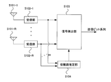
- FIG. 19 is a block diagram showing a configuration of a receiving apparatus in MIMO transmission.
- the reception apparatus includes reception antennas 5101-1 to 5101-R, reception units 5102-1 to 5102-R, a signal detection unit 5103, and a propagation path estimation unit 5104.
- the reception antennas 5101-1 to 5101-R receive the transmission signals that are spatially multiplexed. Reception waves received by reception antennas 5101-1 to 5101-R are converted from radio frequencies to basebands by corresponding reception units 5102-1 to 5102-R, respectively, and output as reception signals.
- the signal detection unit 5103 detects a transmission signal from the received signal and the channel estimation value obtained from the channel estimation unit 5104, and outputs a determination value of the transmission bit sequence.
- the propagation path estimated value 5104 estimates the impulse response of the propagation path using a known training signal for propagation path estimation and the received signal.
- the signal detection unit 5103 detects each transmission signal from the reception signal in which the transmission signal is spatially multiplexed, and there is MLD (Maximum Likelihood Detection) as an optimal detection method.
- MLD Maximum Likelihood Detection
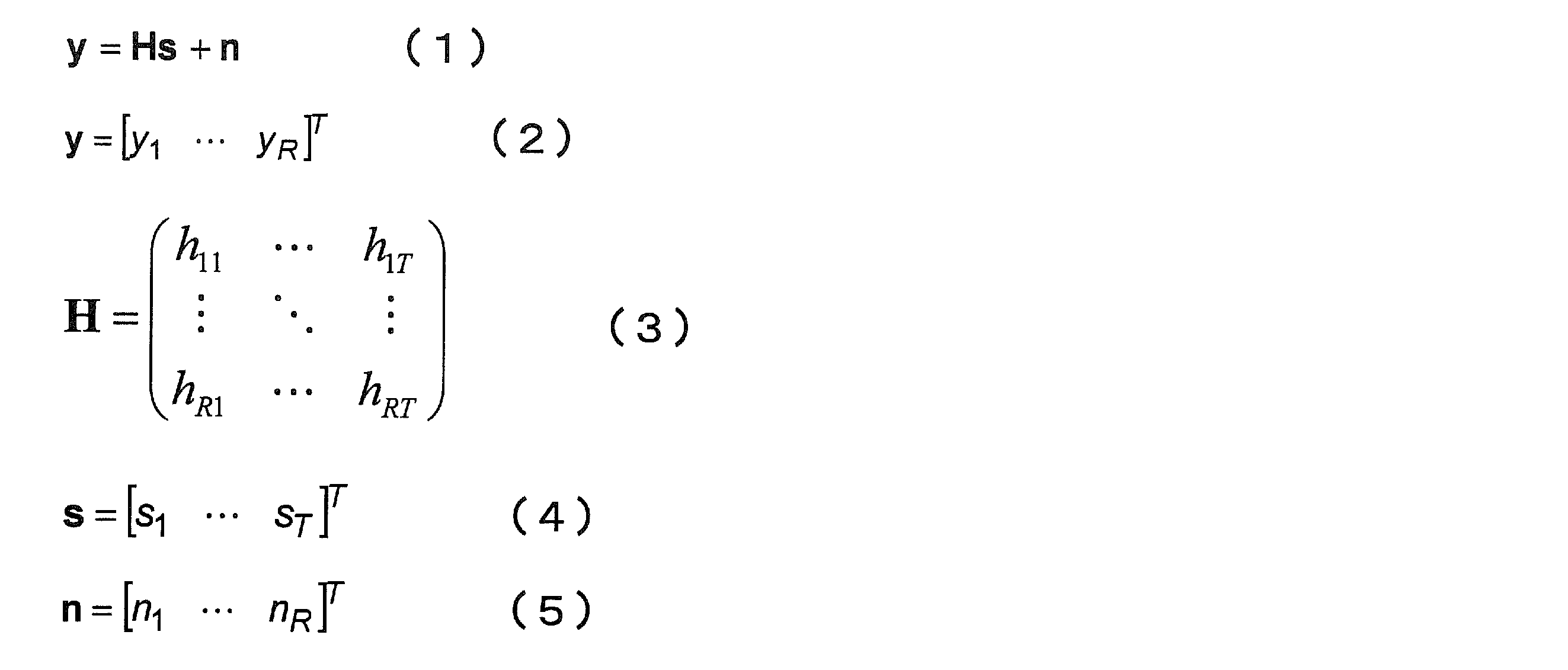
- y is an R-dimensional received signal vector having received signals received by each receiving antenna as elements
- H is an R-row T-column propagation path matrix having elements as propagation impulse responses between the transmitting antenna and the receiving antenna
- s is a T-dimensional transmission signal vector having a transmission signal transmitted from each transmission antenna as an element
- n is an R-dimensional noise vector having noise at each reception antenna as an element.
- T represents transposition of the matrix.
- the MLD detects a transmission signal based on the following criteria based on a reception signal, a propagation path estimation value, and a transmission signal candidate.
- s 1 is a detected T-dimensional transmission signal vector
- H 1 is an R-row T-column propagation path estimated value matrix having estimated propagation path impulse responses as elements
- s ⁇ is a transmission signal candidate.
- s ⁇ is all signal patterns transmitted on the transmission side, and in MLD, it is the closest to the received signal among all transmission signal candidates, that is, metric
- a transmission bit is obtained from a transmission signal candidate that minimizes and is output as a determination value.
- the MLD calculates the metric by the number of all transmission signal candidates, so that optimum performance can be obtained, but there is a problem that the amount of calculation becomes enormous. MLD is described in Non-Patent Document 1 described later.
- a linear reception method such as ZF (Zero Forcing) or MMSE (Minimum Mean Square Error).
- the linear reception method is performed by multiplying the reception signal by a T-row R-column weighting coefficient matrix as follows.
- the weighting coefficient matrix W is based on the ZF standard. In the case of MMSE standard, It is.
- H is represents a complex conjugate transposed matrix
- n 2 is noise power
- I T denotes a unit matrix of T rows and T columns.
- a transmission bit sequence can be obtained by making a hard decision on x ⁇ in equation (7). As described above, since the number of transmission signal candidates is substantially 1 in the linear reception method as compared with the MLD, the calculation amount can be greatly reduced. The linear reception method is described in Non-Patent Document 2 described later.
- MLD there is a technique for obtaining good reception performance while searching for a noise enhancement direction as a direction in which reception performance is deteriorated to reduce transmission signal candidates and greatly reducing the amount of calculation.
- a technique for obtaining good reception performance while searching for a noise enhancement direction as a direction in which reception performance is deteriorated to reduce transmission signal candidates and greatly reducing the amount of calculation is described in Patent Document 1 described later.
- FIG. 20 is a block diagram illustrating a configuration of the signal detection unit 5103 disclosed in Patent Document 1.
- the signal detection unit 5103 in Patent Document 1 includes a transmission signal candidate generation unit 5200, a metric generation unit 5206, and a minimum metric detection unit 5207.
- the transmission signal candidate generation unit 5200 includes an initial signal generation unit 5201, addition units 5202-1 to 5202-T, quantization units 5203-1 to 5203-T, a parallel-serial conversion unit 5204, and an update value calculation unit 5205. .
- the initial signal candidate generation unit 5200 generates transmission signal candidates.
- the initial signal generation unit 5201 generates an initial signal by multiplying the reception signal by a weight based on ZF or MMSE as in Expression (8) or Expression (9).
- Adders 5202-1 to 5202-T add the initial value and the update value obtained by update value calculator 5205.
- the addition result is hard-determined by the quantization units 5203-1 to 5203-T, and parallel-serial converted by the parallel-serial conversion unit 5204, thereby generating transmission signal candidates.
- Update value calculation section 5205 obtains an update value from the received signal, the initial signal, and the propagation path estimation value as in the following equation. If the update value is u, Is required.
- q is an integer greater than or equal to 1
- y is a received signal vector
- s ⁇ (0) is a hard decision result of the initial signal.
- (X ⁇ ) t , (v) t represents the t-th element of x ⁇ and v, respectively.
- a (m) can take the value of the modulation multi-level number M for one t. Since the transmitted signal candidates by adding the updated value to the initial signal is obtained by hard decision, the number of mu r, ie TM number of candidate is obtained. Maximum likelihood detection is performed on the obtained TM candidates. When over conventional MLD in M T as candidates compared to have performed a metric computation can be greatly reduced the number of transmitted signal candidates.
- error correction coding is usually performed to improve reception performance.
- a soft-decision error-correcting decoding that performs error-correcting decoding on a log likelihood ratio (LLR) that is bit reliability information is known as one that provides excellent error correction decoding performance.
- LLR log likelihood ratio
- Patent Document 1 does not consider the operation of the bit LLR.
- the present invention has been made in view of such circumstances, and an object of the present invention is to provide a receiving apparatus and a receiving apparatus that can obtain good reception performance while reducing the amount of calculation in a MIMO communication system using a soft decision error correction code. It is to provide a method and a communication system.
- the present invention is a receiving apparatus that performs communication in a MIMO system, A channel estimation unit for calculating a channel estimation value, a signal detection unit for calculating a bit log likelihood ratio of a transmission signal from a received signal, and a decoding unit for performing error correction decoding processing of the bit log likelihood ratio.
- the signal detection unit determines a transmission signal candidate generation unit that generates a transmission signal candidate, a metric generation unit that generates a metric for the transmission signal candidate, and a transmission signal candidate that is a minimum metric among the metrics as a maximum likelihood sequence.
- the transmission signal candidate generation unit includes an initial signal generation unit that generates an initial signal, an update value calculation unit that calculates an update value for the initial signal, an addition unit that adds the initial signal and the update value, and the addition unit A quantization unit that hard-decides the addition result of and generates the transmission signal candidate,
- the update value calculation unit calculates a step size based on a search direction generation unit that calculates a direction in which reception performance deteriorates based on at least the propagation path estimation value, and a direction in which the initial signal and the reception performance deteriorate.
- a step size generation unit and a direction in which the reception performance deteriorates and an update value generation unit that calculates the update value from the step size.
- the initial signal generation unit generates an initial signal by multiplying the received signal by a weighting factor calculated from the propagation path estimation value, or generates a transmission signal replica from a bit log likelihood ratio output by the decoding unit. It is generated and used as an initial signal.
- the search direction generation unit calculates at least one direction indicating noise enhancement, which is a direction in which reception performance deteriorates, based on the weighting factor.
- the search direction generation unit calculates at least one direction indicating the noise enhancement by a power method.
- the search direction generation unit further performs a hard decision on the initial signal, and calculates a direction indicating the noise enhancement based on a metric gradient of the hard decision result.
- the likelihood calculation unit obtains the bit log likelihood ratio by further considering the bit log likelihood ratio output by the decoding unit.
- the step size generation unit generates the step size so that the initial signal is updated to a different hard decision region.
- the likelihood calculating unit generates a simple metric from the step size, determines an inverted bit sequence of the maximum likelihood sequence that minimizes the simple metric, and determines the bit from the inverted bit sequence and the metric of the maximum likelihood sequence. A log likelihood ratio is calculated.
- the likelihood calculating unit a fixed signal removing unit that removes a signal including an inverted bit with respect to the maximum likelihood sequence, a transmission signal candidate generating unit that generates a transmission signal candidate for the output of the fixed signal removing unit, A metric generation unit that generates a metric for the transmission signal candidate; obtains a minimum metric of the metrics and sets it as an inverted bit metric; and calculates the bit log likelihood ratio from the inverted bit metric and the maximum likelihood sequence metric And a likelihood calculating unit.
- the present invention is also a receiving apparatus that performs communication in a MIMO system, A channel estimation unit for calculating a channel estimation value, a signal detection unit for calculating a bit log likelihood ratio of a transmission signal from a received signal, and a decoding unit for performing error correction decoding processing of the bit log likelihood ratio.
- the signal detection unit includes an approximate metric generation unit and a likelihood calculation unit
- the approximate metric generation unit includes a fixed signal removal unit that removes a modulation signal fixed in a certain transmission antenna, a transmission signal candidate generation unit that generates a transmission signal candidate with respect to an output of the fixed signal removal unit, and the transmission signal
- a metric generation unit for calculating a metric for a candidate, and a minimum metric generation unit for obtaining a minimum metric among the metrics
- the likelihood calculation unit calculates a bit log likelihood ratio of a maximum likelihood sequence from the metric output by the approximate metric generation unit
- the transmission signal candidate generation unit includes an initial signal generation unit that generates an initial signal, an update value calculation unit that calculates an update value for the initial signal, an addition unit that adds the initial signal and the update value, and the addition unit A quantization unit that hard-decides the addition result of and generates the transmission signal candidate
- the update value calculation unit calculates a step size based on a search direction generation unit that calculates a direction in which
- the initial signal generation unit generates an initial signal by multiplying the received signal by a weighting factor calculated from the propagation path estimation value, or generates a transmission signal replica from a bit log likelihood ratio output by the decoding unit. It is generated and used as an initial signal.
- the search direction generation unit calculates a direction showing the maximum noise enhancement based on the weighting factor using a power method.
- the search direction generation unit performs a hard decision on the initial signal, and calculates the noise enhancement direction based on a metric gradient of the hard decision result.
- the likelihood calculation unit obtains the bit log likelihood ratio by further considering the bit log likelihood ratio output by the decoding unit.
- the present invention is also a receiving method in a receiving apparatus that performs communication in a MIMO system,
- a propagation path estimating step in which the propagation path estimating means calculates a propagation path estimated value; a signal detecting step in which the signal detecting means calculates a bit log likelihood ratio of the transmission signal from the received signal; and a decoding means in which the bit log likelihood ratio is calculated.
- a decoding step for performing error correction decoding processing of The signal detection step includes a transmission signal candidate generation step for generating a transmission signal candidate, a metric generation step for generating a metric for the transmission signal candidate, and a transmission signal candidate that is the minimum metric among the metrics is determined as a maximum likelihood sequence.
- the transmission signal candidate generation step includes an initial signal generation step for generating an initial signal, an update value calculation step for obtaining an update value for the initial signal, an addition step for adding the initial signal and the update value, and the addition unit And a quantization step for generating the transmission signal candidate,
- the update value calculating step includes a search direction generation step for calculating a noise enhancement direction based on at least the propagation path estimation value, a step size generation step for calculating a step size based on the initial signal and the noise enhancement direction, And an update value generation step of calculating the update value from the noise enhancement vector and the step size.
- the present invention is also a receiving method in a receiving apparatus that performs communication in a MIMO system, A propagation path estimating step in which the propagation path estimating means calculates a propagation path estimated value; a signal detecting step in which the signal detecting means calculates a bit log likelihood ratio of the transmission signal from the received signal; and a decoding means in which the bit log likelihood ratio is calculated.
- a decoding step for performing error correction decoding processing of The signal detection step includes an approximate metric generation step and a likelihood calculation step
- the approximate metric generation step includes a fixed signal removal step for removing a modulation signal fixed in a certain transmission antenna, a transmission signal candidate generation step for generating a transmission signal candidate for the output of the fixed signal removal means, and the transmission signal
- a metric generation step for calculating a metric for a candidate; and a minimum metric generation step for obtaining a minimum metric among the metrics.
- the likelihood calculating step calculates a bit log likelihood ratio of the maximum likelihood sequence from the metric output by the approximate metric generating means
- the transmission signal candidate generation step includes an initial signal generation step for generating an initial signal, an update value calculation step for obtaining an update value for the initial signal, an addition step for adding the initial signal and the update value, and the addition step And a quantization step for generating the transmission signal candidate
- the update value calculating step includes a search direction generation step for calculating a noise enhancement direction based on at least the propagation path estimation value, a step size generation step for calculating a step size based on the initial signal and the noise enhancement direction, And an update value generation step of calculating the update value from the noise enhancement vector and the step size.
- the present invention is also a communication system including a transmission device and a reception device that perform communication in a MIMO system,
- the transmitting device transmits at least two different data from a plurality of transmitting antennas;
- the receiving apparatus performs a channel estimation unit that calculates a channel estimation value, a signal detection unit that calculates a bit log likelihood ratio of a transmission signal from a received signal, and an error correction decoding process of the bit log likelihood ratio
- a decoding unit for obtaining data transmitted by the transmission device The signal detection unit determines a transmission signal candidate generation unit that generates a transmission signal candidate, a metric generation unit that generates a metric for the transmission signal candidate, and a transmission signal candidate that is a minimum metric among the metrics as a maximum likelihood sequence.
- the transmission signal candidate generation unit includes an initial signal generation unit that generates an initial signal, an update value calculation unit that calculates an update value for the initial signal, an addition unit that adds the initial signal and the update value, and the addition unit A quantization unit that hard-decides the addition result of and generates the transmission signal candidate,
- the update value calculation unit includes a search direction generation unit that calculates a noise enhancement direction based on at least the propagation path estimation value, a step size generation unit that calculates a step size based on the initial signal and the noise enhancement direction, An update value generation unit that calculates the update value from the noise enhancement vector and the step size.
- the present invention is also a communication system including a transmission device and a reception device that perform communication in a MIMO system,
- the transmitting device transmits at least two different data from a plurality of transmitting antennas;
- the receiving apparatus performs a channel estimation unit that calculates a channel estimation value, a signal detection unit that calculates a bit log likelihood ratio of a transmission signal from a received signal, and an error correction decoding process of the bit log likelihood ratio
- a decoding unit for obtaining data transmitted by the transmission device includes an approximate metric generation unit and a likelihood calculation unit,
- the approximate metric generation unit includes a fixed signal removal unit that removes a modulation signal fixed in a certain transmission antenna, a transmission signal candidate generation unit that generates a transmission signal candidate with respect to an output of the fixed signal removal unit, and the transmission signal
- a metric generation unit for calculating a metric for a candidate, and a minimum metric generation unit for obtaining a minimum metric among the metrics
- the likelihood calculation unit calculates a bit log likelihood
- the transmission signal candidate that is the minimum metric among the metrics for the transmission signal candidate is determined as the maximum likelihood sequence, and the bit log likelihood ratio for the maximum likelihood sequence is calculated, so that soft decision error correction decoding is performed. And reception performance can be improved.
- the search direction generation unit calculates the direction indicating noise enhancement based on the gradient of the metric of the hard decision result based on the power method or the initial signal, based on the weighting factor calculated from the propagation path estimation value, Compared to MLD, the amount of calculation can be greatly reduced, and a candidate close to the actual transmission signal can be selected.
- the likelihood calculating unit obtains the bit log likelihood ratio further considering the bit log likelihood ratio output from the decoding unit, the accuracy of the bit log likelihood ratio is improved.
- the step size generation unit since the step size generation unit generates the step size so that the initial signal is updated to a different hard decision region, the inverted bit sequence can be left as a transmission signal candidate.
- the likelihood calculating unit determines an inverted bit sequence of the maximum likelihood sequence that minimizes the simple metric generated from the step size, and calculates a bit log likelihood ratio from the inverted bit sequence and the metric of the maximum likelihood sequence. Therefore, the metric of the inversion bit can be easily determined, and the calculation amount can be suppressed.
- the likelihood calculation unit obtains the minimum metric from among the metrics for the transmission signal candidate and sets the inverted bit metric and calculates the bit log likelihood ratio from the inverted bit metric and the maximum likelihood sequence metric, noise enhancement is performed. The amount of calculation can be reduced in consideration.
- the approximate metric generation unit calculates a metric for the transmission signal candidate to obtain a minimum metric among the metrics
- the likelihood calculation unit calculates the maximum likelihood from the metric output from the approximate metric generation unit. Since the bit-log-likelihood ratio of the sequence is calculated, the metric calculation can be processed in parallel because the metric for all bits is calculated, not the metric for all the bits, and the maximum likelihood sequence is not determined first. There is.
- FIG. 10 is a block diagram illustrating a configuration of a signal detection unit 5103 disclosed in Patent Document 1.
- T is an integer of 2 or more.
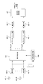
- FIG. 1 is a block diagram illustrating a configuration of a transmission apparatus according to the first embodiment.
- the transmission apparatus includes a serial-parallel conversion unit 301, encoding units 302-1 to 302-T, interleavers 303-1 to 303-T, modulation units 304-1 to 304-T, and transmission units 305-1 to 305-. T and transmission antennas 306-1 to 306-T.
- the transmission bit sequence is serial-parallel converted by the serial-parallel conversion unit 301 and divided into T bit sequences.
- Bit sequences are error-correction-coded using, for example, convolutional codes, turbo codes, LDPC (Low Density Parity Check) codes, etc., by corresponding encoding units 302-1 to 302-T to generate encoded bit sequences. Is done.
- Each coded bit sequence is interleaved by interleavers 303-1 to 303-T.
- the coded bit sequence after the interleaving is mapped to modulation symbols such as QPSK (Quadrature Phase Shift Keying) and 16QAM (Quadrature Amplitude Modulation) by the modulators 304-1 to 304-T.
- Modulation symbols that are transmission signals are converted into radio frequencies by transmission units 305-1 to 305-T, and transmitted from the corresponding transmission antennas 306-1 to 306-T at the same frequency and the same timing.
- FIG. 2 is a block diagram showing the configuration of the receiving apparatus according to the first embodiment.
- the receiving apparatus includes receiving antennas 401-1 to 401-R, receiving units 402-1 to 402-R, signal detecting unit 403, propagation path estimating unit 404, deinterleaver units 405-1 to 405-T, and decoding unit 406-. 1 to 406-T and a parallel-serial converter 407 is provided.
- the reception waves received by the reception antennas 401-1 to 401-R are converted from radio frequencies to baseband signals by the corresponding reception units 402-1 to 402-R, respectively, and output as reception signals.
- the signal detection unit 403 calculates a bit LLR (log likelihood ratio: Log Likelihood Ratio) of the transmission signal from the received signal and the propagation path estimation value obtained from the propagation path estimation unit 404. Details of the signal detection unit 403 will be described later.
- the bit LLRs output from the signal detection unit 403 are rearranged in the deinterleaver units 405-1 to 405-T in the reverse pattern of the interleaving performed on the transmission side.
- the deinterleaved bit LLR is subjected to error correction decoding processing in decoding sections 406-1 to 406-T.
- the decoded bit sequence is parallel-serial converted by the parallel-serial conversion unit 407, and the detected transmission bit sequence is output.
- the signal detection unit 403 performs MLD (Maximum Likelihood Detection) in which transmission signal candidates are reduced.
- a transmission signal candidate is selected by searching for a direction in which reception performance deteriorates. For example, a signal determined by ZF (Zero Forcing) or MMSE (Minimum Mean Square Error) is used as an initial signal, and only signal points near the initial signal are used as transmission signal candidates, and MLD is performed.
- ZF Zero Forcing
- MMSE Minimum Mean Square Error
- FIG. 3 is a block diagram showing a configuration of the signal detection unit 403.
- the signal detection unit 403 includes a transmission signal candidate generation unit 500, a metric generation unit 505, and a likelihood calculation unit 506.
- the transmission signal candidate generation unit 500 includes an initial signal generation unit 501, addition units 502-1 to 502-T, quantization units 503-1 to 503-T, and an update value calculation unit 504.
- Received signals input from the receiving units 402-1 to 402-R are multiplied by a weighting coefficient matrix such as ZF or MMSE in an initial signal generating unit 501 to generate an initial signal.
- Weighting coefficient matrices such as ZF and MMSE are obtained from the channel estimation values input from the channel estimation unit 404 as shown in equations (10) and (11), respectively.
- weighting coefficient matrix W is based on ZF, In the case of the MMSE standard, Is used.
- H 1 is a channel estimation value matrix having a channel estimation value between the transmission antenna and the reception antenna as elements, H represents a complex conjugate transpose matrix, ⁇ n 2 is noise power, and IT is T row T A column identity matrix.
- the update value calculation unit 504 calculates an update value from the initial signal and the propagation path estimated value. Details of the update value will be described later.
- the initial signal and the updated value are added by the adders 502-1 to 502-T, and the addition result is hard-decided by the quantizers 503-1 to 503-T and generated as a transmission signal candidate.
- the metric generation unit 505 generates a metric of the generated transmission signal candidate. Is obtained by calculating.
- s c represents a transmission signal candidate generated by the transmission signal candidate generation unit 500.
- the likelihood calculation unit 506 selects a transmission signal candidate that is the minimum metric from the metrics generated by the metric generation unit 505, and calculates a bit LLR of the selected transmission signal candidate.
- Bit LLR is information necessary for soft decision error correction decoding.
- the likelihood calculating unit 506 calculates the likelihood as follows.
- ⁇ t, n the n-th bit LLR of the modulation symbol transmitted from the t-th transmission antenna.
- ⁇ t, n can be determined by the difference between the minimum metric at the time of the minimum metric and b over the time of b +.
- mu r is the step size
- v represents a T-dimensional vector representing the noise enhanced direction. That is, the transmission signal candidate is searched by moving the initial signal by the step size in the noise enhancement direction.
- FIG. 4A is a block diagram of the update value calculation unit 205 using the first method.
- the search direction generation unit 1702a uses the received signal input from the reception unit, the propagation path estimation value input from the propagation path estimation unit, and the hard decision result of the initial signal in Expression (13). Thus, a direction indicating noise enhancement is generated.
- q is an integer greater than or equal to 1
- y is a received signal vector
- s ⁇ (0) is a hard decision result of the initial signal.
- the step size generation unit 1703a generates a step size from v and the initial signal generated by the search direction generation unit 1702a.
- Updating value generator 1704a obtains the update value as in equation (12) using a mu r and v.
- the second method is a method in which the eigenvector of the maximum eigenvalue of the matrix P in Expression (14) is v.
- FIG. 4B is a block diagram of the update value calculation unit 205 using the second method.
- the search direction generation unit 1702b generates a direction indicating noise enhancement based on the channel estimation value input from the channel estimation unit.
- the matrix P in the equation (14) is a factor of noise enhancement, and its maximum eigenvalue is the maximum component that causes noise enhancement. Therefore, the eigenvector of the maximum eigenvalue of the matrix P is v.
- the eigenvector of the maximum eigenvalue is obtained as follows using, for example, a power method.
- i is an integer of 1 or more.
- the operations of (15) and (16) are repeated several times, and v i finally obtained may be set to v.
- the initial vector v 1 may be an arbitrary vector having a size of 1.
- EDD Eigen Value Decomposition
- step size generating unit 1703b search direction generator is generated in 1702b v and the initial signal step size based on the generated initial signal input from the unit mu r is generated.
- Updating value generator 1704b determines updating value as in equation (12) from mu r and v.
- the noise enhancement direction v is obtained based on the received signal, the hard decision value of the initial signal, and the propagation path estimation value.
- noise enhancement is performed based on the propagation path estimation value.
- the direction v is obtained. Therefore, for the second method, it is not necessary to input the reception signal from the reception unit to the update value calculation unit 504 in FIG. The same applies to the following embodiments.
- a (m) can take the value of the modulation multi-level number M for one t.
- the modulation method is QPSK
- the possible value of a (m) is There are four ways. Since the transmitted signal candidates by adding the updated value to the initial signal is obtained by hard decision, the number of mu r, ie TM number of candidate is obtained. Maximum likelihood detection is performed on the obtained TM candidates.
- the step size there may be an overlapping candidate among the obtained TM transmission signal candidates, so by making the overlapping candidate one candidate, the number of candidates can be further reduced. It becomes possible. It should be noted that another signal point may be newly added as a candidate for the amount reduced by overlapping.
- the number of candidates is determined by the number of step sizes, it is possible to narrow down candidates by the value of step size in order to further reduce the number of candidates. For example, in order to prevent searching for signal points that are too far apart because the step size is too large, select only a step size that is less than or equal to a threshold value among TM step sizes, or have a small absolute value of the step size You can also select a default number from. By reducing only the transmission signal candidates obtained from the selected step size, the amount of calculation can be further reduced.
- the reception performance can be improved.
- the method for calculating the bit LLR when combined with error correction is shown.
- the minimum metric of the inverted bit sequence is required, and therefore the same level as the MLD. Is required.
- the minimum metric of the remaining inverted bit sequence can be used if the inverted bit sequence remains in the candidate when calculating the LLR.
- transmission signal candidates are searched for transmission signal candidates in order to obtain a maximum likelihood sequence. In this case, there is a possibility that the inverted bit sequence does not remain in the transmission signal candidate, and in this case, the bit LLR cannot be calculated.
- a transmission signal candidate reduction method considering calculation of the bit LLR will be described.
- the method of leaving the inverted bit sequence as a transmission signal candidate can be performed by extending the method described with reference to FIG. 4B in the first embodiment, for example.
- the method of the first embodiment described with reference to FIG. 4B effectively reduces the number of transmission signal candidates by searching for the eigenvector of the maximum eigenvalue of Equation (14) as the noise enhancement direction.
- not only the maximum eigenvalue but also a search using eigenvectors of a plurality of eigenvalues makes it easier for an inverted bit sequence to remain in a transmission signal candidate.
- FIG. 5 is a block diagram illustrating a configuration of the update value calculation unit described in the first embodiment.
- the update value calculation unit includes a search direction generation unit 3001, a step size generation unit 3002, and an update value generation unit 3003. The processing of the search direction generation unit 3001 will be described.
- a plurality of eigenvectors of Expression (14) are obtained using the power method as follows. First, the initial matrix P 1 is set to P.
- the specified number of times is p times, and v p, 1 after repeating the number of times p is the eigenvector of the maximum eigenvalue for P 1 .
- the eigenvector v p, 2 of the maximum eigenvalue of P 2 is obtained by the same method. In this manner, P 3 and subsequent Ps are similarly obtained, and eigenvectors v p, 1 to v p, D of the maximum eigenvalues for P 1 to P D and the respective values are obtained, and v p, 1 to v p, D are set as search directions. To do. D is an integer of 1 or more and T or less. Further, v p, 1 to v p, D indicate that noise is enhanced in the order of 1 to D. Since v p, 1 to v p, D are eigenvectors, v p, 1 to v p, D are orthogonal to each other.
- the probability that an inverted bit sequence is included can be increased. Further, although it has been described that the number of repetitions for obtaining each of v p, 1 to v p, D is p times, a different number of repetitions may be set for each of v p, 1 to v p, D.
- the update value In order to leave the inverted bit sequence as a transmission signal candidate, the update value must be calculated so that it is updated to a region different from the hard decision region of the initial signal. Since the update value is calculated from the step size, the step size is important for updating the initial signal. For example, in the case of QPSK modulation, if the hard decision value of the initial signal is (0, 0), the initial signal needs to be updated in a region where the hard decision is (1, 0). For this purpose, it is necessary that ⁇ > 0, and if ⁇ becomes too large, it is far from the initial signal, and therefore ⁇ is preferably in the vicinity of 0 such as 0.001.
- the update value generation unit 3003 generates an update value as shown in Expression (12) from the search direction and step size generated by the search direction generation unit 3001. In the second embodiment, v in Expression (12) is v p, 1 to v p, D.
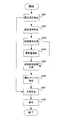
- FIG. 6 is a flowchart of the reception process in the second embodiment.
- an initial signal is generated using a weight such as MMSE or ZF for the received signal.
- step s3102 as a search direction, a plurality of eigenvectors of a part that causes noise enhancement among weights such as MMSE and ZF are obtained in the order in which noise is enhanced.
- step size s3103 based on the search direction and the initial signal, the step size is calculated so that an inverted bit sequence remains as a candidate. Generate candidates.
- a metric for the transmission signal candidate is calculated.
- the maximum likelihood sequence and its bit LLR are calculated from the metric generated in step s3106.
- step s3108 error correction decoding is performed on the bit LLR.
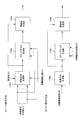
- FIG. 7 is a block diagram showing the configuration of the signal detection unit 403 in the third embodiment.
- the difference from the signal detection unit 403 of the second embodiment is that the step size is output from the update value calculation unit 604 to the likelihood calculation unit 606.
- the likelihood calculating unit 606 selects a transmission signal candidate that is the minimum metric, and obtains a metric of an inverted bit of the selected transmission signal candidate in consideration of the step size. Therefore, here, the update value calculation unit 604 and the likelihood calculation unit 606 will be mainly described.
- the likelihood calculation unit 606 first selects a transmission signal candidate that is the smallest among the metrics input from the metric generation unit 605. As the bit LLR of the selected transmission signal candidate, if the metric generation unit 605 generates a metric of an inverted bit sequence, the smallest one of the generated metrics may be used. If not generated, using the step size mu r, selects the inverted bit sequence to be generated metric. For example, it is assumed that the number of transmission antennas is two and each is transmitted by QPSK. Let s 1 and s 2 be the transmission signals at each transmission antenna.
- the transmission bit sequence is composed of 4 bits, and there are 16 transmission signal candidates.
- the transmission bit sequence is assumed to be (b 1,1 , b 1,2 , b 2,1 , b 2,2 ).
- b i, j represents the j-th bit of the i-th transmitting antenna.
- bit sequence that is the minimum metric is (0, 0, 0, 0). It is assumed that there is no inverted bit sequence for the first bit. In the case of obtaining with high accuracy, the bit LLR must be calculated using the smallest metric among the eight sequences whose first bit is 1, which increases the amount of calculation. Therefore, a simple metric is calculated from the step size obtained by the update value calculation unit 604, an inverted bit sequence that is the minimum metric is determined, a metric of the determined bit sequence is calculated, and a bit LLR is calculated.
- the modulation scheme is QPSK
- mu r is eight.
- Bits (0, 0), (0, 1), (1, 1), (1, 0) constituting QPSK are numbered 1, 2, 3, 4 respectively.
- ⁇ 1 to ⁇ 4 correspond to the QPSK numbering in the first transmission antenna
- ⁇ 5 to ⁇ 8 correspond to the numbering 1, 2, 3, 4 in the second transmission antenna, respectively.
- a simple metric of (1, 0, 0, 1) which is one of the inverted bit sequences, has a step size ⁇ 4 when calculated as (1, 0) with the first transmitting antenna and ( It is represented by the sum of absolute values of the step size ⁇ 6 calculated as 0, 1).
- the simple metric (1, 1, 1, 0) is represented by the sum of absolute values of ⁇ 3 and ⁇ 8 .
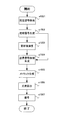
- FIG. 8 is a flowchart showing the reception process of the third embodiment.
- a received signal is input, and an initial signal is generated by, for example, MMSE or ZF (step s701).
- the initial signal is passed to steps s702 and s703.
- step s702 an update value is calculated from the direction vector indicating the direction of deterioration due to noise enhancement calculated based on the propagation path estimation value, the step size searched for the deterioration direction, the direction vector, and the step size.
- the update value is passed to step s703, and the step size is passed to s705.
- the update value is added to the initial signal, and a transmission signal candidate is generated by making a hard decision on the addition result.
- step s704 a metric for each transmission signal candidate is generated.
- step s705 the smallest maximum likelihood sequence among the metrics generated in step s704 is obtained, and a bit LLR for the maximum likelihood sequence is calculated.
- the inverted bit metric necessary for calculating the bit LLR is obtained by obtaining a simple metric from the step size obtained in step s702, selecting a sequence that minimizes the simple metric, and calculating the metric.
- a transmission bit sequence is obtained by error correction decoding processing in step s706. The reception process ends after outputting the transmission bit sequence obtained in step s706.
- the inverted bit sequence for calculating the metric may be determined as a bit sequence in which only the bit corresponding to the bit LLR to be obtained is inverted. For example, when obtaining the LLR of the first bit for (0, 0, 0, 0), the inverted bit sequence is (1, 0, 0, 0), and for the second bit (0, 1, 0, 0) ).
- the inverted bit sequence that is the minimum metric is simply determined using the step size.
- another bit LLR calculation method will be described.
- FIG. 9 is a block diagram showing the configuration of the signal detection unit in the fourth embodiment.
- the signal detection unit includes a transmission signal candidate generation unit 1500, a metric generation unit 1505, and a likelihood calculation unit 1506.
- the transmission signal candidate generation unit 1500 includes an initial signal generation unit 1501, addition units 1502-1 to 1502-T, quantization units 1503-1 to 1503-T, and an update value calculation unit 1504.
- the signal detection unit of the fourth embodiment is almost the same as that of the second embodiment. Since the difference is processing in the likelihood calculation unit 1506, only the details of the likelihood calculation unit 1506 will be described here.
- FIG. 10 is a block diagram showing a configuration of the likelihood calculation unit 1506 in the fourth embodiment.
- the likelihood calculation unit includes a minimum metric generation unit 1601, a fixed signal removal unit 1602, a transmission signal candidate generation unit 1603, a metric generation unit 1604, and a likelihood calculation unit 1605.
- a sequence that is the minimum metric is detected as a maximum likelihood sequence.
- the maximum likelihood sequence is passed to the fixed signal removal unit 1602, and the minimum metric is passed to the likelihood calculation unit 1605.
- the modulation method is QPSK and the determination bit of s ⁇ t is (1, 0).
- the possible values of the inverted bits are (0, 0) and (0, 1) with respect to 1 of the first bit of the determination bit of s ⁇ t .
- a possible value of the inverted bit of the n-th bit of the transmission signal at the t-th transmission antenna is ⁇ q .
- q is 1 ⁇ q ⁇ Q, It is.
- I a vector having ⁇ q as the t-th element and 0 as the other elements.
- the fixed signal removal unit 1602 As described above, the component including the inverted bit is removed from the received signal y.
- H R rows except the first column t from ⁇ (T-1) is a matrix of columns.
- the transmission signal candidate generation unit 1603 generates transmission signal candidates as described in the first embodiment for Expression (23).
- the metric generation unit 1604 calculates a metric for each transmission signal candidate. At this time, a metric when the t-th element of the transmission signal is ⁇ q is calculated.
- the likelihood calculating unit 1605 obtains the minimum metric L t, n, q among the metrics generated by the metric generating unit 1604. The minimum metric is obtained for all q, and the smallest one of L t, n, 1 to L t, n, Q is set as the inverted bit metric L t, n, and the second metric is obtained using L t, n . Calculate the LLR of the nth bit of the k transmit antenna.
- the LLR can be obtained for all bits.
- the initial signal for reducing the number of candidates when calculating the LLR may be the maximum likelihood sequence obtained first without using MMSE. In that case, since the MMSE process is not required, the calculation amount is reduced.
- FIG. 11 is a flowchart showing a reception process in the fourth embodiment.
- step s801 the maximum likelihood sequence is detected from the received signal and its metric is generated.
- steps s802 to s805 a bit LLR for the maximum likelihood sequence detected in step s801 is calculated.
- step s802 a signal for fixing the inverted bit for a certain signal included in the maximum likelihood sequence is obtained and removed from the received signal.
- an initial signal is generated by MMSE or the like for the signal from which the fixed signal has been removed.
- step s804 an updated value is obtained in consideration of noise enhancement.
- step s805 a transmission signal candidate is generated for the initial signal and the signal obtained by removing the fixed signal from the update value.
- step s806 a metric is calculated for each transmission signal candidate, and a minimum metric is output.
- step s807 a bit LLR is calculated from the metric of the maximum likelihood sequence obtained in step s801 and the metric of its inverted bit.
- step s808 error correction decoding is performed, the obtained transmission bit sequence is output, and the process ends.
- the calculation amount is smaller than that of the MLD. It can be greatly reduced.
- the maximum likelihood sequence is not calculated first, and the bit LLR calculation method described in the fourth embodiment is used to calculate the LLRs of all bits.
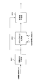
- FIG. 12 is a block diagram showing the configuration of the signal detection unit in the fifth embodiment.
- the signal detection unit includes approximate metric generation units 901-1 to 901-TM and a likelihood calculation unit 906.
- the approximate metric generation units 901-1 to 901-TM include a fixed signal removal unit 902, a transmission signal candidate generation unit 903, a metric generation unit 904, and a minimum metric generation unit 905.
- the received signal input from the receiving unit is input to the approximate metric generating units 901-1 to 901-TM.
- Each of the approximate metric generation units 901-1 to 901-TM removes the corresponding fixed signal from the received signal by the fixed signal removal unit 902.
- a transmission signal candidate generation unit 903 generates a transmission signal candidate for the signal after the fixed signal is removed.
- the metric generation unit 904 calculates a metric using the generated transmission signal candidate, the signal after removal of the fixed signal, and the channel estimation value input from the channel estimation unit.
- the minimum metric 905 outputs the minimum metric obtained from the metric generation unit 904.
- the likelihood calculation unit 906 obtains the maximum likelihood sequence from the metrics output from the approximate metric generation units 901-1 to 901-TM, and uses the metric of the maximum likelihood sequence and the inverted bit metric of the maximum likelihood sequence to generate a bit LLR. Is calculated.
- Equation (21) is newly expressed as follows.
- the maximum likelihood sequence is not obtained first, it is necessary to consider not only the inverted bits but also M patterns.
- the fixed signal removal unit 902 fixes the signal using Expression (26). Is removed from the received signal.
- FIG. 13 is a flowchart of the reception process in the fifth embodiment.
- step s1001 a transmission signal transmitted from a certain transmission antenna is fixed and removed from the reception signal.
- step s1002 MMSE or ZF is performed on the signal after the fixed signal is removed, and an initial signal is generated.
- step s1003 an update value in the noise enhancement direction is calculated.
- step s1004 a transmission signal candidate for the signal after the fixed signal is removed is generated from the initial signal and the updated value.
- the metric of each transmission signal candidate is calculated.
- step s1006 the maximum likelihood sequence and its bit LLR are calculated using the metric generated in step s1005.
- step s1007 error correction decoding is performed, a transmission bit sequence is output, and the process ends.
- the fifth embodiment not only the metric for the inverted bit but also the metric for all the bits is calculated. Since the maximum likelihood sequence is not determined first, there is an advantage that the metric calculation can be processed in parallel.
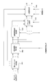
- FIG. 14 is a block diagram showing a configuration of a receiving apparatus according to the sixth embodiment.
- the reception apparatus includes reception antennas 1101-1 to 1101-R, reception units 1102-1 to 1102-R, signal detection unit 1103, propagation path estimation unit 1104, deinterleaver units 1105-1 to 1105-T, and decoding unit 1106. -1 to 1106-T and a parallel-serial converter 1107.
- Received waves received by the receiving antennas 1101-1 to 1101-R are converted from radio frequencies to baseband signals by the corresponding receiving units 1102-1 to 1102-R, respectively, and output as received signals.
- the signal detection unit 1103 detects a MIMO signal from the received signal, the bit LLR obtained from the decoding units 1106-1 to 1106-T, and the channel estimation value obtained from the channel estimation unit 1104.
- the deinterleaver units 1105-1 to 1105-T rearrange the bit LLRs in the reverse pattern of the interleaving process performed on the transmitting side, and the decoding units 1106-1 to 1106-T perform error correction decoding processing.
- the bit sequence obtained by the decoding process is parallel-serial converted by the parallel-serial conversion unit 1107, and the transmission bit sequence is output. If there is an error in the decoding result, the bit LLR obtained by the error correction decoding process is input to the signal detection section 1103. For example, CRC (Cyclic Redundancy Check) may be used for error determination of the decoding result. If the decoding process has never been performed, the bit LLR is not calculated, so that the signal detection unit 1103 performs the process without using the bit LLR.
- CRC Cyclic Redundancy Check
- FIG. 15 is a block diagram illustrating a configuration of the signal detection unit 1103.
- the signal detection unit 1103 includes a transmission signal candidate generation unit 1200, a metric generation unit 1205, and a likelihood calculation unit 1206.
- the transmission signal candidate generation unit 1200 includes an initial signal generation unit 1201, addition units 1202-1 to 1202-T, quantization units 1203-1 to 1203-T, and an update value calculation unit 1204.
- the blocks using the bit LLR are the initial signal generation unit 1201 and the likelihood calculation unit 1206, and the other blocks are the same as those described in the first to fifth embodiments. Will be omitted.
- FIG. 16 is a block diagram showing a configuration of the initial signal generation unit 1201.
- the initial signal generation unit 1201 includes interleaver units 1301-1 to 1301-T and symbol replica generation units 1302-1 to 1302-T. Bit LLRs are interleaved by interleavers 1301-1 to 1301-T in the same pattern as that on the transmission side.
- Symbol replica generation sections 1302-1 to 1302-T generate a transmission signal replica by generating a symbol replica of the modulation scheme performed on the transmission side from the interleaved bit LLR, and output the transmission signal replica as an initial signal To do.
- the modulation scheme is QPSK
- symbol replica generation sections 1302-1 to 1302-T perform the following processing.
- the replica of the QPSK modulation symbol is Is generated as follows.
- the likelihood calculating unit 1206 uses the metric generated by the metric generating unit 1205 and the bit LLR output from the decoding units 1106-1 to 1106-T to generate the bit LLRs input to the decoding units 1106-1 to 1106-T.
- the bit LLR input to the decoding unit may be modified from equation (18) as equation (29).
- bit LLR As an approximate expression of Expression (29), the bit LLR can also be obtained as shown in Expression (30).
- the bit LLR output from the likelihood calculation unit 1206 is input to the decoding units 1106-1 to 1106-T. Such repetition of error correction decoding and MIMO signal detection ends when no error is detected or a predetermined number of decoding processes are performed.
- FIG. 17 is a flowchart of the reception process of the sixth embodiment.
- step s1501 an initial signal is generated. If error correction decoding has never been performed, the initial signal is obtained from the received signal by MMSE or ZF. This initial signal is passed to steps s1502 and s1503.
- step s1502 an update value is calculated from the direction vector indicating the direction of deterioration due to noise enhancement calculated based on the propagation path estimated value, the step size searched for the deterioration direction, the direction vector, and the step size.
- step s1503 the initial signal and the update value are added, and a transmission signal candidate is generated by making a hard decision.
- step s1504 the metric of each transmission signal candidate generated in step s1503 is calculated.
- step s1505 the maximum likelihood sequence and its bit LLR are calculated from the metric obtained in step s1504. Since the decoding process has not been performed at this time, no consideration is given to the calculation of the LLR.
- step s1506 error correction decoding is performed on the bit LLR obtained in step s1505.
- step s1507 it is determined whether there is an error in the bit sequence of the decoding result. If it is determined that there is no error, the bit sequence is output and the process is terminated. If it is determined that there is an error, the decoded bit LLR is passed to steps s1501 and s1505, and the process returns to step s1501 again.
- step s1501 after the decoding process is performed once, a replica of the modulation symbol is generated from the bit LLR obtained by the decoding process, and an initial signal is generated.
- step s1502 a step size for searching in the deterioration direction is obtained based on the generated initial signal, and an update value is calculated from the initially obtained direction vector and step size.
- step s1503 the initial signal and the updated value are added and a transmission signal candidate is generated by making a hard decision.
- step s1504 calculates the metric of each transmission signal candidate.
- step s1505 the bit LLR of the maximum likelihood sequence is obtained from the metric generated in step s1504 and the bit LLR of the decoding result.
- step s1506 bit LLR error correction decoding processing is performed. If there is an error in the decoding result, the process returns to step s1501 and the same processing is performed.
- the performance of both the MIMO signal detection and the decoding process can be effectively improved by repeatedly performing the MIMO signal detection and the decoding process.
- the bit LLR output from the decoding units 1106-1 to 1106-T is used in both the initial signal generation unit 1201 and the likelihood calculation unit 1206 is shown, but both need to be used.
- the initial signal generator 1201 may use the bit LLR and the likelihood calculator 1206 may not use the bit LLR.
- the initial signal generator 1201 may not use the bit LLR and the likelihood calculator 1206 may use the bit LLR.
- LLR may be used.
- the initial signal generated first may be obtained using MMSE or the like.
- the receiving apparatus of the second embodiment is extended to use the bit LLR output from the decoding unit.
- the bit LLR output from the decoding unit is also provided. It is possible to extend when using.
- this invention is not limited to this, The same data is transmitted by some transmission antennas among several transmission antennas used. Is also included. In that case, the receiving side may detect different transmitted data.
- the narrowband single carrier MIMO scheme has been described.
- the present invention is not limited to this, and for example, MIMO-OFDM (Orthogonal Frequency Division Multiplexing) or MIMO-MC-CDMA (Multi Carrier-Code Division).
- a multi-carrier scheme such as Multiple Access or a single-carrier scheme that performs MIMO signal separation in the frequency domain can be used in the same manner.
- MIMO signal separation in the frequency domain for example, if the received signal is transformed into the frequency domain by Fourier transform, an independent narrowband MIMO signal appears at each frequency. Therefore, the first to sixth embodiments can be easily applied. can do.
Abstract
Description
受信装置は、受信アンテナ5101-1~5101-R、受信部5102-1~5102-R、信号検出部5103、伝搬路推定部5104を備える。 FIG. 19 is a block diagram showing a configuration of a receiving apparatus in MIMO transmission.
The reception apparatus includes reception antennas 5101-1 to 5101-R, reception units 5102-1 to 5102-R, a


伝搬路推定値を算出する伝搬路推定部と、受信信号から送信信号のビット対数尤度比を算出する信号検出部と、前記ビット対数尤度比の誤り訂正復号処理を行なう復号部と、を備え、
前記信号検出部は、送信信号候補を生成する送信信号候補生成部と、前記送信信号候補に対するメトリックを生成するメトリック生成部と、前記メトリックのうち最小メトリックとなる送信信号候補を最尤系列として決定し、該最尤系列に対するビット対数尤度比を算出する尤度演算部と、を備え、
前記送信信号候補生成部は、初期信号を生成する初期信号生成部と、前記初期信号に対する更新値を求める更新値演算部と、前記初期信号と前記更新値を加算する加算部と、前記加算部の加算結果を硬判定し、前記送信信号候補を生成する量子化部と、を備え、
前記更新値演算部は、少なくとも前記伝搬路推定値に基づいて受信性能が劣化する方向を算出する探索方向生成部と、前記初期信号および前記受信性能が劣化する方向に基づいてステップサイズを算出するステップサイズ生成部と、前記受信性能が劣化する方向および前記ステップサイズから前記更新値を算出する更新値生成部と、を備えることを特徴とする。 The present invention is a receiving apparatus that performs communication in a MIMO system,
A channel estimation unit for calculating a channel estimation value, a signal detection unit for calculating a bit log likelihood ratio of a transmission signal from a received signal, and a decoding unit for performing error correction decoding processing of the bit log likelihood ratio. Prepared,
The signal detection unit determines a transmission signal candidate generation unit that generates a transmission signal candidate, a metric generation unit that generates a metric for the transmission signal candidate, and a transmission signal candidate that is a minimum metric among the metrics as a maximum likelihood sequence. A likelihood calculating unit that calculates a bit log likelihood ratio for the maximum likelihood sequence,
The transmission signal candidate generation unit includes an initial signal generation unit that generates an initial signal, an update value calculation unit that calculates an update value for the initial signal, an addition unit that adds the initial signal and the update value, and the addition unit A quantization unit that hard-decides the addition result of and generates the transmission signal candidate,
The update value calculation unit calculates a step size based on a search direction generation unit that calculates a direction in which reception performance deteriorates based on at least the propagation path estimation value, and a direction in which the initial signal and the reception performance deteriorate. A step size generation unit; and a direction in which the reception performance deteriorates and an update value generation unit that calculates the update value from the step size.
伝搬路推定値を算出する伝搬路推定部と、受信信号から送信信号のビット対数尤度比を算出する信号検出部と、前記ビット対数尤度比の誤り訂正復号処理を行なう復号部と、を備え、
前記信号検出部は、近似メトリック生成部と、尤度演算部と、を備え、
前記近似メトリック生成部は、ある送信アンテナにおいて固定した変調信号を除去する固定信号除去部と、前記固定信号除去部の出力に対し、送信信号候補を生成する送信信号候補生成部と、前記送信信号候補に対するメトリックを計算するメトリック生成部と、前記メトリックのうち、最小のメトリックを求める最小メトリック生成部と、を備え、
前記尤度演算部は、前記近似メトリック生成部が出力するメトリックから、最尤系列のビット対数尤度比を算出し、
前記送信信号候補生成部は、初期信号を生成する初期信号生成部と、前記初期信号に対する更新値を求める更新値演算部と、前記初期信号と前記更新値を加算する加算部と、前記加算部の加算結果を硬判定し、前記送信信号候補を生成する量子化部と、を備え、
前記更新値演算部は、少なくとも前記伝搬路推定値に基づいて受信性能が劣化する方向を算出する探索方向生成部と、前記初期信号および前記受信性能が劣化する方向に基づいてステップサイズを算出するステップサイズ生成部と、前記受信性能が劣化する方向および前記ステップサイズから前記更新値を算出する更新値生成部と、を備えることを特徴とする。 The present invention is also a receiving apparatus that performs communication in a MIMO system,
A channel estimation unit for calculating a channel estimation value, a signal detection unit for calculating a bit log likelihood ratio of a transmission signal from a received signal, and a decoding unit for performing error correction decoding processing of the bit log likelihood ratio. Prepared,
The signal detection unit includes an approximate metric generation unit and a likelihood calculation unit,
The approximate metric generation unit includes a fixed signal removal unit that removes a modulation signal fixed in a certain transmission antenna, a transmission signal candidate generation unit that generates a transmission signal candidate with respect to an output of the fixed signal removal unit, and the transmission signal A metric generation unit for calculating a metric for a candidate, and a minimum metric generation unit for obtaining a minimum metric among the metrics,
The likelihood calculation unit calculates a bit log likelihood ratio of a maximum likelihood sequence from the metric output by the approximate metric generation unit,
The transmission signal candidate generation unit includes an initial signal generation unit that generates an initial signal, an update value calculation unit that calculates an update value for the initial signal, an addition unit that adds the initial signal and the update value, and the addition unit A quantization unit that hard-decides the addition result of and generates the transmission signal candidate,
The update value calculation unit calculates a step size based on a search direction generation unit that calculates a direction in which reception performance deteriorates based on at least the propagation path estimation value, and a direction in which the initial signal and the reception performance deteriorate. A step size generation unit; and a direction in which the reception performance deteriorates and an update value generation unit that calculates the update value from the step size.
伝搬路推定手段が伝搬路推定値を算出する伝搬路推定ステップと、信号検出手段が受信信号から送信信号のビット対数尤度比を算出する信号検出ステップと、復号手段が前記ビット対数尤度比の誤り訂正復号処理を行なう復号ステップと、を備え、
前記信号検出ステップは、送信信号候補を生成する送信信号候補生成ステップと、前記送信信号候補に対するメトリックを生成するメトリック生成ステップと、前記メトリックのうち最小メトリックとなる送信信号候補を最尤系列として決定し、該最尤系列に対するビット対数尤度比を算出する尤度演算ステップと、を備え、
前記送信信号候補生成ステップは、初期信号を生成する初期信号生成ステップと、前記初期信号に対する更新値を求める更新値演算ステップと、前記初期信号と前記更新値を加算する加算ステップと、前記加算部の加算結果を硬判定し、前記送信信号候補を生成する量子化ステップと、を備え、
前記更新値演算ステップは、少なくとも前記伝搬路推定値に基づいて雑音強調方向を算出する探索方向生成ステップと、前記初期信号および前記雑音強調方向に基づいてステップサイズを算出するステップサイズ生成ステップと、前記雑音強調ベクトルおよび前記ステップサイズから前記更新値を算出する更新値生成ステップと、を備えることを特徴とする。 The present invention is also a receiving method in a receiving apparatus that performs communication in a MIMO system,
A propagation path estimating step in which the propagation path estimating means calculates a propagation path estimated value; a signal detecting step in which the signal detecting means calculates a bit log likelihood ratio of the transmission signal from the received signal; and a decoding means in which the bit log likelihood ratio is calculated. A decoding step for performing error correction decoding processing of
The signal detection step includes a transmission signal candidate generation step for generating a transmission signal candidate, a metric generation step for generating a metric for the transmission signal candidate, and a transmission signal candidate that is the minimum metric among the metrics is determined as a maximum likelihood sequence. And a likelihood calculation step for calculating a bit log likelihood ratio for the maximum likelihood sequence,
The transmission signal candidate generation step includes an initial signal generation step for generating an initial signal, an update value calculation step for obtaining an update value for the initial signal, an addition step for adding the initial signal and the update value, and the addition unit And a quantization step for generating the transmission signal candidate,
The update value calculating step includes a search direction generation step for calculating a noise enhancement direction based on at least the propagation path estimation value, a step size generation step for calculating a step size based on the initial signal and the noise enhancement direction, And an update value generation step of calculating the update value from the noise enhancement vector and the step size.
伝搬路推定手段が伝搬路推定値を算出する伝搬路推定ステップと、信号検出手段が受信信号から送信信号のビット対数尤度比を算出する信号検出ステップと、復号手段が前記ビット対数尤度比の誤り訂正復号処理を行なう復号ステップと、を備え、
前記信号検出ステップは、近似メトリック生成ステップと、尤度演算ステップと、を備え、
前記近似メトリック生成ステップは、ある送信アンテナにおいて固定した変調信号を除去する固定信号除去ステップと、前記固定信号除去手段の出力に対し、送信信号候補を生成する送信信号候補生成ステップと、前記送信信号候補に対するメトリックを計算するメトリック生成ステップと、前記メトリックのうち、最小のメトリックを求める最小メトリック生成ステップと、を備え、
前記尤度演算ステップは、前記近似メトリック生成手段が出力するメトリックから、最尤系列のビット対数尤度比を算出し、
前記送信信号候補生成ステップは、初期信号を生成する初期信号生成ステップと、前記初期信号に対する更新値を求める更新値演算ステップと、前記初期信号と前記更新値を加算する加算ステップと、前記加算ステップの加算結果を硬判定し、前記送信信号候補を生成する量子化ステップと、を備え、
前記更新値演算ステップは、少なくとも前記伝搬路推定値に基づいて雑音強調方向を算出する探索方向生成ステップと、前記初期信号および前記雑音強調方向に基づいてステップサイズを算出するステップサイズ生成ステップと、前記雑音強調ベクトルおよび前記ステップサイズから前記更新値を算出する更新値生成ステップと、を備えることを特徴とする。 The present invention is also a receiving method in a receiving apparatus that performs communication in a MIMO system,
A propagation path estimating step in which the propagation path estimating means calculates a propagation path estimated value; a signal detecting step in which the signal detecting means calculates a bit log likelihood ratio of the transmission signal from the received signal; and a decoding means in which the bit log likelihood ratio is calculated. A decoding step for performing error correction decoding processing of
The signal detection step includes an approximate metric generation step and a likelihood calculation step,
The approximate metric generation step includes a fixed signal removal step for removing a modulation signal fixed in a certain transmission antenna, a transmission signal candidate generation step for generating a transmission signal candidate for the output of the fixed signal removal means, and the transmission signal A metric generation step for calculating a metric for a candidate; and a minimum metric generation step for obtaining a minimum metric among the metrics.
The likelihood calculating step calculates a bit log likelihood ratio of the maximum likelihood sequence from the metric output by the approximate metric generating means,
The transmission signal candidate generation step includes an initial signal generation step for generating an initial signal, an update value calculation step for obtaining an update value for the initial signal, an addition step for adding the initial signal and the update value, and the addition step And a quantization step for generating the transmission signal candidate,
The update value calculating step includes a search direction generation step for calculating a noise enhancement direction based on at least the propagation path estimation value, a step size generation step for calculating a step size based on the initial signal and the noise enhancement direction, And an update value generation step of calculating the update value from the noise enhancement vector and the step size.
前記送信装置は、複数の送信アンテナから少なくとも2つの異なるデータを送信し、
前記受信装置は、伝搬路推定値を算出する伝搬路推定部と、受信信号から送信信号のビット対数尤度比を算出する信号検出部と、前記ビット対数尤度比の誤り訂正復号処理を行ない、前記送信装置が送信したデータを求める復号部と、を備え、
前記信号検出部は、送信信号候補を生成する送信信号候補生成部と、前記送信信号候補に対するメトリックを生成するメトリック生成部と、前記メトリックのうち最小メトリックとなる送信信号候補を最尤系列として決定し、該最尤系列に対するビット対数尤度比を算出する尤度演算部と、を備え、
前記送信信号候補生成部は、初期信号を生成する初期信号生成部と、前記初期信号に対する更新値を求める更新値演算部と、前記初期信号と前記更新値を加算する加算部と、前記加算部の加算結果を硬判定し、前記送信信号候補を生成する量子化部と、を備え、
前記更新値演算部は、少なくとも前記伝搬路推定値に基づいて雑音強調方向を算出する探索方向生成部と、前記初期信号および前記雑音強調方向に基づいてステップサイズを算出するステップサイズ生成部と、前記雑音強調ベクトルおよび前記ステップサイズから前記更新値を算出する更新値生成部と、を備えることを特徴とする。 The present invention is also a communication system including a transmission device and a reception device that perform communication in a MIMO system,
The transmitting device transmits at least two different data from a plurality of transmitting antennas;
The receiving apparatus performs a channel estimation unit that calculates a channel estimation value, a signal detection unit that calculates a bit log likelihood ratio of a transmission signal from a received signal, and an error correction decoding process of the bit log likelihood ratio A decoding unit for obtaining data transmitted by the transmission device,
The signal detection unit determines a transmission signal candidate generation unit that generates a transmission signal candidate, a metric generation unit that generates a metric for the transmission signal candidate, and a transmission signal candidate that is a minimum metric among the metrics as a maximum likelihood sequence. A likelihood calculating unit that calculates a bit log likelihood ratio for the maximum likelihood sequence,
The transmission signal candidate generation unit includes an initial signal generation unit that generates an initial signal, an update value calculation unit that calculates an update value for the initial signal, an addition unit that adds the initial signal and the update value, and the addition unit A quantization unit that hard-decides the addition result of and generates the transmission signal candidate,
The update value calculation unit includes a search direction generation unit that calculates a noise enhancement direction based on at least the propagation path estimation value, a step size generation unit that calculates a step size based on the initial signal and the noise enhancement direction, An update value generation unit that calculates the update value from the noise enhancement vector and the step size.
前記送信装置は、複数の送信アンテナから少なくとも2つの異なるデータを送信し、
前記受信装置は、伝搬路推定値を算出する伝搬路推定部と、受信信号から送信信号のビット対数尤度比を算出する信号検出部と、前記ビット対数尤度比の誤り訂正復号処理を行ない、前記送信装置が送信したデータを求める復号部と、を備え、
前記信号検出部は、近似メトリック生成部と、尤度演算部と、を備え、
前記近似メトリック生成部は、ある送信アンテナにおいて固定した変調信号を除去する固定信号除去部と、前記固定信号除去部の出力に対し、送信信号候補を生成する送信信号候補生成部と、前記送信信号候補に対するメトリックを計算するメトリック生成部と、前記メトリックのうち、最小のメトリックを求める最小メトリック生成部と、を備え、
前記尤度演算部は、前記近似メトリック生成部が出力するメトリックから、最尤系列のビット対数尤度比を算出し、
前記送信信号候補生成部は、初期信号を生成する初期信号生成部と、前記初期信号に対する更新値を求める更新値演算部と、前記初期信号と前記更新値を加算する加算部と、前記加算部の加算結果を硬判定し、前記送信信号候補を生成する量子化部と、を備え、
前記更新値演算部は、少なくとも前記伝搬路推定値に基づいて雑音強調方向を算出する探索方向生成部と、前記初期信号および前記雑音強調方向に基づいてステップサイズを算出するステップサイズ生成部と、前記雑音強調ベクトルおよび前記ステップサイズから前記更新値を算出する更新値生成部と、を備えることを特徴とする。 The present invention is also a communication system including a transmission device and a reception device that perform communication in a MIMO system,
The transmitting device transmits at least two different data from a plurality of transmitting antennas;
The receiving apparatus performs a channel estimation unit that calculates a channel estimation value, a signal detection unit that calculates a bit log likelihood ratio of a transmission signal from a received signal, and an error correction decoding process of the bit log likelihood ratio A decoding unit for obtaining data transmitted by the transmission device,
The signal detection unit includes an approximate metric generation unit and a likelihood calculation unit,
The approximate metric generation unit includes a fixed signal removal unit that removes a modulation signal fixed in a certain transmission antenna, a transmission signal candidate generation unit that generates a transmission signal candidate with respect to an output of the fixed signal removal unit, and the transmission signal A metric generation unit for calculating a metric for a candidate, and a minimum metric generation unit for obtaining a minimum metric among the metrics,
The likelihood calculation unit calculates a bit log likelihood ratio of a maximum likelihood sequence from the metric output by the approximate metric generation unit,
The transmission signal candidate generation unit includes an initial signal generation unit that generates an initial signal, an update value calculation unit that calculates an update value for the initial signal, an addition unit that adds the initial signal and the update value, and the addition unit A quantization unit that hard-decides the addition result of and generates the transmission signal candidate,
The update value calculation unit includes a search direction generation unit that calculates a noise enhancement direction based on at least the propagation path estimation value, a step size generation unit that calculates a step size based on the initial signal and the noise enhancement direction, An update value generation unit that calculates the update value from the noise enhancement vector and the step size.
301 直並列変換部
302 符号化部
303 インターリーバ部
304 変調部
305 送信部
306 送信アンテナ
401 受信アンテナ
402 受信部
403 信号検出部
404 伝搬路推定部
405 デインターリーバ部
406 復号部
407 並直列変換部
500 送信信号候補生成部
501 初期信号生成部
502 加算部
503 量子化部
504 更新値演算部
505 メトリック生成部
506 尤度演算部
604 更新値演算部
605 メトリック生成部
606 尤度演算部
901 近似メトリック生成部
902 固定信号除去部
903 送信信号候補生成部
904 メトリック生成部
905 最小メトリック生成部
906 尤度演算部
1101 受信アンテナ
1102 受信部
1103 信号検出部
1104 伝搬路推定部
1105 デインターリーバ部
1106 復号部
1107 並直列変換部
1200 送信信号候補生成部
1201 初期信号生成部
1202 加算部
1203 量子化部
1204 更新値演算部
1205 メトリック生成部
1206 尤度演算部
1301 インターリーバ部
1302 シンボルレプリカ生成部
1500 送信信号候補生成部
1501 初期信号生成部
1502 加算部
1503 量子化部
1504 更新値演算部
1505 メトリック生成部
1506 尤度演算部
1601 最小メトリック生成部
1602 固定信号除去部
1603 送信信号候補生成部
1604 メトリック生成部
1605 尤度算出部
1702a 探索方向生成部
1702b 探索方向生成部
1703a ステップサイズ生成部
1703b ステップサイズ生成部
1704a 更新値生成部
1704b 更新値生成部
3001 探索方向生成部
3002 ステップサイズ生成部
3003 更新値生成部 205 Update Value Calculation Unit 301 Series-Parallel Conversion Unit 302 Encoding Unit 303 Interleaver Unit 304 Modulation Unit 305 Transmission Unit 306 Transmission Antenna 401 Reception Antenna 402 Reception Unit 403 Signal Detection Unit 404 Propagation Channel Estimation Unit 405 Deinterleaver Unit 406 Decoding Unit 407 Parallel-serial converter 500 Transmission signal candidate generator 501 Initial signal generator 502 Adder 503 Quantizer 504 Update value calculator 505 Metric generator 506 Likelihood calculator 604 Update value calculator 605 Metric generator 606 Likelihood calculation Unit 901 approximate metric generation unit 902 fixed signal removal unit 903 transmission signal candidate generation unit 904 metric generation unit 905 minimum metric generation unit 906 likelihood calculation unit 1101 reception antenna 1102 reception unit 1103 signal detection unit 1104 propagation path estimation unit 1105 deinterleaving Unit 1106 decoding unit 1107 parallel-serial conversion unit 1200 transmission signal candidate generation unit 1201 initial signal generation unit 1202 addition unit 1203 quantization unit 1204 update value calculation unit 1205 metric generation unit 1206 likelihood calculation unit 1301 interleaver unit 1302 symbol replica generation unit 1500 Transmission signal candidate generation unit 1501 Initial signal generation unit 1502 Addition unit 1503 Quantization unit 1504 Update value calculation unit 1505 Metric generation unit 1506 Likelihood calculation unit 1601 Minimum metric generation unit 1602 Fixed signal removal unit 1603 Transmission signal candidate generation unit 1604 Metric Generation unit 1605 Likelihood calculation unit 1702a Search direction generation unit 1702b Search direction generation unit 1703a Step size generation unit 1703b Step size generation unit 1704a Update value generation unit 1704b Update value generation unit 300 Search direction generator 3002 step size generating unit 3003 updating value generator
図1は第1の実施形態における送信装置の構成を示すブロック図である。送信装置は、直並列変換部301、符号化部302-1~302-T、インターリーバ部303-1~303-T、変調部304-1~304-T、送信部305-1~305-T、送信アンテナ306-1~306-Tを備える。送信ビット系列は直並列変換部301で直列並列変換されT個のビット系列に分けられる。ビット系列は各々対応する符号化部302-1~302-Tで、例えば畳込み符号、ターボ符号、LDPC(Low Density Parity Check)符号等を用いて誤り訂正符号化され、符号化ビット系列が生成される。各符号化ビット系列はインターリーバ部303-1~303-Tでインターリーブが行なわれる。インターリーブ後の符号化ビット系列は変調部304-1~304-TでQPSK(Quadrature Phase Shift Keying)や16QAM(Quadrature Amplitude Modulation)などの変調シンボルにマッピングされる。送信信号である変調シンボルは、送信部305-1~305-Tにて無線周波数に変換され、各々対応する送信アンテナ306-1~306-Tから同一周波数、同一タイミングで送信される。 (First embodiment)
FIG. 1 is a block diagram illustrating a configuration of a transmission apparatus according to the first embodiment. The transmission apparatus includes a serial-


第1の実施形態では誤り訂正と組み合わせた場合に、ビットLLRの算出方法を示したが、最適なビットLLRを求める際には、反転ビット系列のうち最小メトリックが必要なため、MLDと同程度の演算量が必要となる。送信信号候補数を削減したMLDの場合には、LLRを算出する際に、反転ビット系列が候補に残っていれば、残っている反転ビット系列の最小メトリックを用いることができる。しかし、第1の実施形態では送信信号候補は最尤系列を求めるために送信信号候補を探索していた。この場合、反転ビット系列が送信信号候補に残らない可能性があり、そのときはビットLLRの計算できなくなる。第2の実施形態では、ビットLLRを算出することを考慮した送信信号候補削減方法を説明する。 (Second Embodiment)
In the first embodiment, the method for calculating the bit LLR when combined with error correction is shown. However, when obtaining the optimum bit LLR, the minimum metric of the inverted bit sequence is required, and therefore the same level as the MLD. Is required. In the case of MLD in which the number of transmission signal candidates is reduced, the minimum metric of the remaining inverted bit sequence can be used if the inverted bit sequence remains in the candidate when calculating the LLR. However, in the first embodiment, transmission signal candidates are searched for transmission signal candidates in order to obtain a maximum likelihood sequence. In this case, there is a possibility that the inverted bit sequence does not remain in the transmission signal candidate, and in this case, the bit LLR cannot be calculated. In the second embodiment, a transmission signal candidate reduction method considering calculation of the bit LLR will be described.


第3の実施形態ではステップサイズを用いて簡易的にビットLLRを算出する方法を説明する。
第3の実施形態では、第1の実施形態で生成したステップサイズを用いて、メトリックを生成すべき反転ビット系列を決定し、決定した反転ビット系列のメトリックを生成し、ビットLLRを算出する方法を説明する。 (Third embodiment)
In the third embodiment, a method for simply calculating the bit LLR using the step size will be described.
In the third embodiment, a method of determining an inverted bit sequence for generating a metric using the step size generated in the first embodiment, generating a metric of the determined inverted bit sequence, and calculating a bit LLR Will be explained.


第5の実施形態では、最初に最尤系列を求めず、第4の実施形態で説明したビットLLR算出方法を用い、全ビットのLLRを算出する場合を示す。 (Fifth embodiment)
In the fifth embodiment, the maximum likelihood sequence is not calculated first, and the bit LLR calculation method described in the fourth embodiment is used to calculate the LLRs of all bits.

第6の実施形態は、誤り訂正復号結果を利用して、MIMO検出を繰り返し行なう。 (Sixth embodiment)
In the sixth embodiment, MIMO detection is repeatedly performed using an error correction decoding result.


Claims (18)
- MIMOシステムにて通信を行う受信装置であって、
伝搬路推定値を算出する伝搬路推定部と、
受信信号から送信信号のビット対数尤度比を算出する信号検出部と、
前記ビット対数尤度比の誤り訂正復号処理を行なう復号部と、
を備え、
前記信号検出部は、
送信信号候補を生成する送信信号候補生成部と、
前記送信信号候補に対するメトリックを生成するメトリック生成部と、
前記メトリックのうち最小メトリックとなる送信信号候補を最尤系列として決定し、該最尤系列に対するビット対数尤度比を算出する尤度演算部と、
を備え、
前記送信信号候補生成部は、
初期信号を生成する初期信号生成部と、
前記初期信号に対する更新値を求める更新値演算部と、
前記初期信号と前記更新値を加算する加算部と、
前記加算部の加算結果を硬判定し、前記送信信号候補を生成する量子化部と、
を備え、
前記更新値演算部は、
少なくとも前記伝搬路推定値に基づいて受信性能が劣化する方向を算出する探索方向生成部と、
前記初期信号および前記受信性能が劣化する方向に基づいてステップサイズを算出するステップサイズ生成部と、
前記受信性能が劣化する方向および前記ステップサイズから前記更新値を算出する更新値生成部と、
を備えることを特徴とする受信装置。 A receiving device that performs communication in a MIMO system,
A propagation path estimation unit for calculating a propagation path estimated value;
A signal detector that calculates a bit log likelihood ratio of the transmission signal from the reception signal;
A decoding unit for performing error correction decoding processing of the bit log likelihood ratio;
With
The signal detector is
A transmission signal candidate generator for generating transmission signal candidates;
A metric generator for generating a metric for the transmission signal candidate;
A likelihood calculating unit that determines a transmission signal candidate that is a minimum metric among the metrics as a maximum likelihood sequence, and calculates a bit log likelihood ratio for the maximum likelihood sequence;
With
The transmission signal candidate generation unit
An initial signal generator for generating an initial signal;
An update value calculation unit for obtaining an update value for the initial signal;
An adder for adding the initial signal and the updated value;
A quantization unit that hard-decides the addition result of the addition unit and generates the transmission signal candidate;
With
The update value calculator is
A search direction generation unit that calculates a direction in which reception performance deteriorates based on at least the propagation path estimation value;
A step size generation unit that calculates a step size based on the initial signal and a direction in which the reception performance deteriorates;
An update value generation unit that calculates the update value from the direction in which the reception performance deteriorates and the step size;
A receiving apparatus comprising: - 前記初期信号生成部は、
前記伝搬路推定値から算出される重み係数を前記受信信号に乗算して初期信号を生成する、
或いは、前記復号部が出力するビット対数尤度比から送信信号レプリカを生成して初期信号とすることを特徴とする請求項1に記載の受信装置。 The initial signal generator is
Multiplying the received signal by a weighting factor calculated from the propagation path estimation value to generate an initial signal;
Alternatively, the reception apparatus according to claim 1, wherein a transmission signal replica is generated from a bit log likelihood ratio output by the decoding unit and used as an initial signal. - 前記探索方向生成部は、前記重み係数に基づいて、受信性能が劣化する方向である雑音強調を示す方向を少なくとも1つ算出することを特徴とする請求項2に記載の受信装置。 The reception apparatus according to claim 2, wherein the search direction generation unit calculates at least one direction indicating noise enhancement, which is a direction in which reception performance deteriorates, based on the weighting factor.
- 前記探索方向生成部は、べき乗法により前記雑音強調を示す方向を少なくとも1つ算出することを特徴とする請求項3に記載の受信装置。 The receiving device according to claim 3, wherein the search direction generation unit calculates at least one direction indicating the noise enhancement by a power method.
- 前記探索方向生成部は、さらに前記初期信号を硬判定し、該硬判定結果のメトリックの勾配により前記雑音強調を示す方向を算出することを特徴とする請求項3に記載の受信装置。 The receiving apparatus according to claim 3, wherein the search direction generation unit further performs a hard decision on the initial signal and calculates a direction indicating the noise enhancement based on a metric gradient of the hard decision result.
- 前記尤度演算部は、前記復号部が出力するビット対数尤度比をさらに考慮して前記ビット対数尤度比を求めることを特徴とする請求項1から5のいずれかに記載の受信装置。 6. The receiving apparatus according to claim 1, wherein the likelihood calculating unit obtains the bit log likelihood ratio by further considering a bit log likelihood ratio output by the decoding unit.
- 前記ステップサイズ生成部は、前記初期信号が、異なる硬判定領域に更新されるように、前記ステップサイズを生成することを特徴とする請求項1から6のいずれかに記載の受信装置。 The reception apparatus according to any one of claims 1 to 6, wherein the step size generation unit generates the step size so that the initial signal is updated to a different hard decision region.
- 前記尤度演算部は、前記ステップサイズから簡易メトリックを生成し、前記簡易メトリックが最小となる前記最尤系列の反転ビット系列を決定し、該反転ビット系列および前記最尤系列のメトリックから前記ビット対数尤度比を算出することを特徴とする請求項1から7のいずれかに記載の受信装置。 The likelihood calculating unit generates a simple metric from the step size, determines an inverted bit sequence of the maximum likelihood sequence that minimizes the simple metric, and determines the bit from the inverted bit sequence and the metric of the maximum likelihood sequence. The receiver according to claim 1, wherein a log likelihood ratio is calculated.
- 前記尤度演算部は、
前記最尤系列に対する反転ビットを含む信号を除去する固定信号除去部と、
前記固定信号除去部の出力に対し、送信信号候補を生成する送信信号候補生成部と、
前記送信信号候補に対するメトリックを生成するメトリック生成部と、
前記メトリックのうち最小メトリックを求め反転ビットのメトリックとし、該反転ビットのメトリックおよび前記最尤系列のメトリックから前記ビット対数尤度比を算出する尤度算出部と、
を備えることを特徴とする請求項1から7のいずれかに記載の受信装置。 The likelihood calculator is
A fixed signal removal unit for removing a signal including an inverted bit with respect to the maximum likelihood sequence;
A transmission signal candidate generation unit that generates a transmission signal candidate for the output of the fixed signal removal unit;
A metric generator for generating a metric for the transmission signal candidate;
A likelihood calculating unit that obtains a minimum metric of the metrics and sets the inverted bit metric, and calculates the bit log likelihood ratio from the inverted bit metric and the metric of the maximum likelihood sequence;
The receiving apparatus according to claim 1, further comprising: - MIMOシステムにて通信を行う受信装置であって、
伝搬路推定値を算出する伝搬路推定部と、
受信信号から送信信号のビット対数尤度比を算出する信号検出部と、
前記ビット対数尤度比の誤り訂正復号処理を行なう復号部と、
を備え、
前記信号検出部は、近似メトリック生成部と、尤度演算部と、を備え、
前記近似メトリック生成部は、
ある送信アンテナにおいて固定した変調信号を除去する固定信号除去部と、
前記固定信号除去部の出力に対し、送信信号候補を生成する送信信号候補生成部と、
前記送信信号候補に対するメトリックを計算するメトリック生成部と、
前記メトリックのうち、最小のメトリックを求める最小メトリック生成部と、
を備え、
前記尤度演算部は、前記近似メトリック生成部が出力するメトリックから、最尤系列のビット対数尤度比を算出し、
前記送信信号候補生成部は、
初期信号を生成する初期信号生成部と、
前記初期信号に対する更新値を求める更新値演算部と、
前記初期信号と前記更新値を加算する加算部と、
前記加算部の加算結果を硬判定し、前記送信信号候補を生成する量子化部と、
を備え、
前記更新値演算部は、
少なくとも前記伝搬路推定値に基づいて受信性能が劣化する方向を算出する探索方向生成部と、
前記初期信号および前記受信性能が劣化する方向に基づいてステップサイズを算出するステップサイズ生成部と、
前記受信性能が劣化する方向および前記ステップサイズから前記更新値を算出する更新値生成部と、
を備えることを特徴とする受信装置。 A receiving device that performs communication in a MIMO system,
A propagation path estimation unit for calculating a propagation path estimated value;
A signal detector that calculates a bit log likelihood ratio of the transmission signal from the reception signal;
A decoding unit for performing error correction decoding processing of the bit log likelihood ratio;
With
The signal detection unit includes an approximate metric generation unit and a likelihood calculation unit,
The approximate metric generation unit includes:
A fixed signal removing unit for removing a modulation signal fixed in a certain transmission antenna;
A transmission signal candidate generation unit that generates a transmission signal candidate for the output of the fixed signal removal unit;
A metric generator for calculating a metric for the transmission signal candidate;
Among the metrics, a minimum metric generation unit for obtaining a minimum metric,
With
The likelihood calculation unit calculates a bit log likelihood ratio of a maximum likelihood sequence from the metric output by the approximate metric generation unit,
The transmission signal candidate generation unit
An initial signal generator for generating an initial signal;
An update value calculation unit for obtaining an update value for the initial signal;
An adder for adding the initial signal and the updated value;
A quantization unit that hard-decides the addition result of the addition unit and generates the transmission signal candidate;
With
The update value calculator is
A search direction generation unit that calculates a direction in which reception performance deteriorates based on at least the propagation path estimation value;
A step size generation unit that calculates a step size based on the initial signal and a direction in which the reception performance deteriorates;
An update value generation unit that calculates the update value from the direction in which the reception performance deteriorates and the step size;
A receiving apparatus comprising: - 前記初期信号生成部は、
前記伝搬路推定値から算出される重み係数を前記受信信号に乗算して初期信号を生成する、
或いは、前記復号部が出力するビット対数尤度比から送信信号レプリカを生成して初期信号とすることを特徴とする請求項10に記載の受信装置。 The initial signal generator is
Multiplying the received signal by a weighting factor calculated from the propagation path estimation value to generate an initial signal;
Alternatively, the reception apparatus according to claim 10, wherein a transmission signal replica is generated from a bit log likelihood ratio output by the decoding unit and used as an initial signal. - 前記探索方向生成部は、前記重み係数に基づいて、最大の雑音強調を示す方向を、べき乗法を用いて算出することを特徴とする請求項10に記載の受信装置。 The receiving device according to claim 10, wherein the search direction generation unit calculates a direction showing the maximum noise enhancement based on the weighting factor using a power method.
- 前記探索方向生成部は、前記初期信号を硬判定し、該硬判定結果のメトリックの勾配に基づいて前記雑音強調方向を算出することを特徴とする請求項10に記載の受信装置。 The receiving apparatus according to claim 10, wherein the search direction generation unit performs a hard decision on the initial signal and calculates the noise enhancement direction based on a metric gradient of the hard decision result.
- 前記尤度演算部は、前記復号部が出力するビット対数尤度比をさらに考慮して前記ビット対数尤度比を求めることを特徴とする請求項10から13のいずれかに記載の受信装置。 14. The receiving apparatus according to claim 10, wherein the likelihood calculating unit obtains the bit log likelihood ratio further considering a bit log likelihood ratio output by the decoding unit.
- MIMOシステムにて通信を行なう受信装置における受信方法であって、
伝搬路推定手段が伝搬路推定値を算出する伝搬路推定ステップと、
信号検出手段が受信信号から送信信号のビット対数尤度比を算出する信号検出ステップと、
復号手段が前記ビット対数尤度比の誤り訂正復号処理を行なう復号ステップと、
を備え、
前記信号検出ステップは、
送信信号候補を生成する送信信号候補生成ステップと、
前記送信信号候補に対するメトリックを生成するメトリック生成ステップと、
前記メトリックのうち最小メトリックとなる送信信号候補を最尤系列として決定し、該最尤系列に対するビット対数尤度比を算出する尤度演算ステップと、
を備え、
前記送信信号候補生成ステップは、
初期信号を生成する初期信号生成ステップと、
前記初期信号に対する更新値を求める更新値演算ステップと、
前記初期信号と前記更新値を加算する加算ステップと、
前記加算部の加算結果を硬判定し、前記送信信号候補を生成する量子化ステップと、
を備え、
前記更新値演算ステップは、
少なくとも前記伝搬路推定値に基づいて雑音強調方向を算出する探索方向生成ステップと、
前記初期信号および前記雑音強調方向に基づいてステップサイズを算出するステップサイズ生成ステップと、
前記雑音強調ベクトルおよび前記ステップサイズから前記更新値を算出する更新値生成ステップと、
を備えることを特徴とする受信方法。 A receiving method in a receiving apparatus that performs communication in a MIMO system,
A channel estimation step in which the channel estimation means calculates a channel estimation value;
A signal detection step in which the signal detection means calculates a bit log likelihood ratio of the transmission signal from the reception signal;
A decoding step in which decoding means performs an error correction decoding process of the bit log likelihood ratio;
With
The signal detection step includes
A transmission signal candidate generation step for generating transmission signal candidates;
A metric generation step of generating a metric for the transmission signal candidate;
A likelihood calculating step of determining a transmission signal candidate that is a minimum metric among the metrics as a maximum likelihood sequence, and calculating a bit log likelihood ratio for the maximum likelihood sequence;
With
The transmission signal candidate generation step includes:
An initial signal generating step for generating an initial signal;
An update value calculation step for obtaining an update value for the initial signal;
An adding step of adding the initial signal and the updated value;
A quantization step of hard-decision of the addition result of the adding unit and generating the transmission signal candidate;
With
The update value calculation step includes:
A search direction generation step of calculating a noise enhancement direction based on at least the propagation path estimated value;
A step size generation step for calculating a step size based on the initial signal and the noise enhancement direction;
An update value generation step of calculating the update value from the noise enhancement vector and the step size;
A receiving method comprising: - MIMOシステムにて通信を行う受信装置における受信方法であって、
伝搬路推定手段が伝搬路推定値を算出する伝搬路推定ステップと、
信号検出手段が受信信号から送信信号のビット対数尤度比を算出する信号検出ステップと、
復号手段が前記ビット対数尤度比の誤り訂正復号処理を行なう復号ステップと、
を備え、
前記信号検出ステップは、近似メトリック生成ステップと、尤度演算ステップと、を備え、
前記近似メトリック生成ステップは、
ある送信アンテナにおいて固定した変調信号を除去する固定信号除去ステップと、
前記固定信号除去手段の出力に対し、送信信号候補を生成する送信信号候補生成ステップと、
前記送信信号候補に対するメトリックを計算するメトリック生成ステップと、
前記メトリックのうち、最小のメトリックを求める最小メトリック生成ステップと、
を備え、
前記尤度演算ステップは、前記近似メトリック生成手段が出力するメトリックから、最尤系列のビット対数尤度比を算出し、
前記送信信号候補生成ステップは、
初期信号を生成する初期信号生成ステップと、
前記初期信号に対する更新値を求める更新値演算ステップと、
前記初期信号と前記更新値を加算する加算ステップと、
前記加算ステップの加算結果を硬判定し、前記送信信号候補を生成する量子化ステップと、
を備え、
前記更新値演算ステップは、
少なくとも前記伝搬路推定値に基づいて雑音強調方向を算出する探索方向生成ステップと、
前記初期信号および前記雑音強調方向に基づいてステップサイズを算出するステップサイズ生成ステップと、
前記雑音強調ベクトルおよび前記ステップサイズから前記更新値を算出する更新値生成ステップと、
を備えることを特徴とする受信方法。 A receiving method in a receiving apparatus that performs communication in a MIMO system,
A channel estimation step in which the channel estimation means calculates a channel estimation value;
A signal detection step in which the signal detection means calculates a bit log likelihood ratio of the transmission signal from the reception signal;
A decoding step in which decoding means performs an error correction decoding process of the bit log likelihood ratio;
With
The signal detection step includes an approximate metric generation step and a likelihood calculation step,
The approximate metric generation step includes:
A fixed signal removal step for removing a fixed modulation signal in a certain transmission antenna;
A transmission signal candidate generation step of generating a transmission signal candidate for the output of the fixed signal removing means;
A metric generation step of calculating a metric for the transmission signal candidate;
A minimum metric generation step for obtaining a minimum metric among the metrics,
With
The likelihood calculating step calculates a bit log likelihood ratio of the maximum likelihood sequence from the metric output by the approximate metric generating means,
The transmission signal candidate generation step includes:
An initial signal generating step for generating an initial signal;
An update value calculation step for obtaining an update value for the initial signal;
An adding step of adding the initial signal and the updated value;
A quantization step of making a hard decision on the addition result of the addition step and generating the transmission signal candidate;
With
The update value calculation step includes:
A search direction generation step of calculating a noise enhancement direction based on at least the propagation path estimated value;
A step size generation step for calculating a step size based on the initial signal and the noise enhancement direction;
An update value generation step of calculating the update value from the noise enhancement vector and the step size;
A receiving method comprising: - MIMOシステムにて通信を行なう送信装置と受信装置とを備える通信ステムであって、
前記送信装置は、複数の送信アンテナから少なくとも2つの異なるデータを送信し、
前記受信装置は、
伝搬路推定値を算出する伝搬路推定部と、
受信信号から送信信号のビット対数尤度比を算出する信号検出部と、
前記ビット対数尤度比の誤り訂正復号処理を行ない、前記送信装置が送信したデータを求める復号部と、
を備え、
前記信号検出部は、
送信信号候補を生成する送信信号候補生成部と、
前記送信信号候補に対するメトリックを生成するメトリック生成部と、
前記メトリックのうち最小メトリックとなる送信信号候補を最尤系列として決定し、該最尤系列に対するビット対数尤度比を算出する尤度演算部と、
を備え、
前記送信信号候補生成部は、
初期信号を生成する初期信号生成部と、
前記初期信号に対する更新値を求める更新値演算部と、
前記初期信号と前記更新値を加算する加算部と、
前記加算部の加算結果を硬判定し、前記送信信号候補を生成する量子化部と、
を備え、
前記更新値演算部は、
少なくとも前記伝搬路推定値に基づいて雑音強調方向を算出する探索方向生成部と、
前記初期信号および前記雑音強調方向に基づいてステップサイズを算出するステップサイズ生成部と、
前記雑音強調ベクトルおよび前記ステップサイズから前記更新値を算出する更新値生成部と、
を備えることを特徴とする通信システム。 A communication system comprising a transmission device and a reception device that perform communication in a MIMO system,
The transmitting device transmits at least two different data from a plurality of transmitting antennas;
The receiving device is:
A propagation path estimation unit for calculating a propagation path estimated value;
A signal detector that calculates a bit log likelihood ratio of the transmission signal from the reception signal;
A decoding unit that performs error correction decoding processing of the bit log likelihood ratio and obtains data transmitted by the transmission device;
With
The signal detector is
A transmission signal candidate generator for generating transmission signal candidates;
A metric generator for generating a metric for the transmission signal candidate;
A likelihood calculating unit that determines a transmission signal candidate that is a minimum metric among the metrics as a maximum likelihood sequence, and calculates a bit log likelihood ratio for the maximum likelihood sequence;
With
The transmission signal candidate generation unit
An initial signal generator for generating an initial signal;
An update value calculation unit for obtaining an update value for the initial signal;
An adder for adding the initial signal and the updated value;
A quantization unit that hard-decides the addition result of the addition unit and generates the transmission signal candidate;
With
The update value calculator is
A search direction generation unit that calculates a noise enhancement direction based on at least the propagation path estimation value;
A step size generator that calculates a step size based on the initial signal and the noise enhancement direction;
An update value generation unit that calculates the update value from the noise enhancement vector and the step size;
A communication system comprising: - MIMOシステムにて通信を行なう送信装置と受信装置とを備える通信ステムであって、
前記送信装置は、複数の送信アンテナから少なくとも2つの異なるデータを送信し、
前記受信装置は、
伝搬路推定値を算出する伝搬路推定部と、
受信信号から送信信号のビット対数尤度比を算出する信号検出部と、
前記ビット対数尤度比の誤り訂正復号処理を行ない、前記送信装置が送信したデータを求める復号部と、
を備え、
前記信号検出部は、
近似メトリック生成部と、
尤度演算部と、
を備え、
前記近似メトリック生成部は、
ある送信アンテナにおいて固定した変調信号を除去する固定信号除去部と、
前記固定信号除去部の出力に対し、送信信号候補を生成する送信信号候補生成部と、
前記送信信号候補に対するメトリックを計算するメトリック生成部と、
前記メトリックのうち、最小のメトリックを求める最小メトリック生成部と、
を備え、
前記尤度演算部は、前記近似メトリック生成部が出力するメトリックから、最尤系列のビット対数尤度比を算出し、
前記送信信号候補生成部は、
初期信号を生成する初期信号生成部と、
前記初期信号に対する更新値を求める更新値演算部と、
前記初期信号と前記更新値を加算する加算部と、
前記加算部の加算結果を硬判定し、前記送信信号候補を生成する量子化部と、
を備え、
前記更新値演算部は、
少なくとも前記伝搬路推定値に基づいて雑音強調方向を算出する探索方向生成部と、
前記初期信号および前記雑音強調方向に基づいてステップサイズを算出するステップサイズ生成部と、
前記雑音強調ベクトルおよび前記ステップサイズから前記更新値を算出する更新値生成部と、
を備えることを特徴とする通信システム。 A communication system comprising a transmission device and a reception device that perform communication in a MIMO system,
The transmitting device transmits at least two different data from a plurality of transmitting antennas;
The receiving device is:
A propagation path estimation unit for calculating a propagation path estimated value;
A signal detector that calculates a bit log likelihood ratio of the transmission signal from the reception signal;
A decoding unit that performs error correction decoding processing of the bit log likelihood ratio and obtains data transmitted by the transmission device;
With
The signal detector is
An approximate metric generator;
A likelihood calculator,
With
The approximate metric generation unit includes:
A fixed signal removing unit for removing a modulation signal fixed in a certain transmission antenna;
A transmission signal candidate generation unit that generates a transmission signal candidate for the output of the fixed signal removal unit;
A metric generator for calculating a metric for the transmission signal candidate;
Among the metrics, a minimum metric generation unit for obtaining a minimum metric,
With
The likelihood calculation unit calculates a bit log likelihood ratio of a maximum likelihood sequence from the metric output by the approximate metric generation unit,
The transmission signal candidate generation unit
An initial signal generator for generating an initial signal;
An update value calculation unit for obtaining an update value for the initial signal;
An adder for adding the initial signal and the updated value;
A quantization unit that hard-decides the addition result of the addition unit and generates the transmission signal candidate;
With
The update value calculator is
A search direction generation unit that calculates a noise enhancement direction based on at least the propagation path estimation value;
A step size generator that calculates a step size based on the initial signal and the noise enhancement direction;
An update value generation unit that calculates the update value from the noise enhancement vector and the step size;
A communication system comprising:
Priority Applications (3)
| Application Number | Priority Date | Filing Date | Title |
|---|---|---|---|
| EP09707160.9A EP2242196A4 (en) | 2008-02-05 | 2009-02-04 | Reception device, reception method, and communication system |
| CN2009801116549A CN101981846B (en) | 2008-02-05 | 2009-02-04 | Reception device, reception method, and communication system |
| US12/866,175 US8218671B2 (en) | 2008-02-05 | 2009-02-04 | Receiving apparatus, receiving method and communication system |
Applications Claiming Priority (2)
| Application Number | Priority Date | Filing Date | Title |
|---|---|---|---|
| JP2008025604A JP5043702B2 (en) | 2008-02-05 | 2008-02-05 | Receiving apparatus, receiving method, and communication system |
| JP2008-025604 | 2008-02-05 |
Publications (1)
| Publication Number | Publication Date |
|---|---|
| WO2009099097A1 true WO2009099097A1 (en) | 2009-08-13 |
Family
ID=40952171
Family Applications (1)
| Application Number | Title | Priority Date | Filing Date |
|---|---|---|---|
| PCT/JP2009/051878 WO2009099097A1 (en) | 2008-02-05 | 2009-02-04 | Reception device, reception method, and communication system |
Country Status (5)
| Country | Link |
|---|---|
| US (1) | US8218671B2 (en) |
| EP (1) | EP2242196A4 (en) |
| JP (1) | JP5043702B2 (en) |
| CN (1) | CN101981846B (en) |
| WO (1) | WO2009099097A1 (en) |
Cited By (1)
| Publication number | Priority date | Publication date | Assignee | Title |
|---|---|---|---|---|
| WO2014175430A1 (en) * | 2013-04-26 | 2014-10-30 | 国立大学法人東京工業大学 | Reception apparatus, reception method and reception program |
Families Citing this family (14)
| Publication number | Priority date | Publication date | Assignee | Title |
|---|---|---|---|---|
| JP5157928B2 (en) * | 2009-01-16 | 2013-03-06 | 日本電気株式会社 | Receiving apparatus and signal receiving method |
| US9131402B2 (en) | 2010-12-10 | 2015-09-08 | The Trustees Of Columbia University In The City Of New York | Methods, systems, and media for detecting usage of a radio channel |
| US9479372B2 (en) * | 2012-03-08 | 2016-10-25 | The Trustees Of Columbia University In The City Of New York | Methods, systems, and media for determining whether a signal of interest is present |
| JP2014049822A (en) * | 2012-08-29 | 2014-03-17 | Tokyo Institute Of Technology | Reception device, reception method and program |
| KR101537346B1 (en) * | 2012-10-10 | 2015-07-16 | 주식회사 케이티 | Server and method for providing web contents for iptv |
| CN103873203B (en) * | 2012-12-10 | 2017-05-24 | 电信科学技术研究院 | Signal detection method and device |
| JP6603543B2 (en) * | 2015-10-27 | 2019-11-06 | 日本放送協会 | Transmitter and receiver |
| US10142145B2 (en) * | 2015-11-27 | 2018-11-27 | Cohda Wireless Pty Ltd. | Wireless receiver |
| CN107359923B (en) * | 2016-05-09 | 2023-01-13 | 瑞昱半导体股份有限公司 | Maximum likelihood detector and method, and wireless signal receiver |
| CN109792266B (en) * | 2016-11-11 | 2022-04-29 | 日本电信电话株式会社 | Wireless device and wireless communication method |
| WO2019041085A1 (en) * | 2017-08-28 | 2019-03-07 | 中国科学技术大学 | Method and device for decoding signal, and storage device |
| FR3111034B1 (en) * | 2020-05-29 | 2022-09-02 | Commissariat Energie Atomique | Machine-learning demodulation method for energy-sensing MIMO receivers |
| CN112564769B (en) * | 2020-11-30 | 2022-08-26 | 东方红卫星移动通信有限公司 | Low-orbit satellite high-speed communication method, transmitting terminal and system with multi-rate hierarchical adjustment |
| US11799700B1 (en) * | 2022-08-31 | 2023-10-24 | Qualcomm Incorporated | Decoding multi-level coded (MLC) systems |
Citations (1)
| Publication number | Priority date | Publication date | Assignee | Title |
|---|---|---|---|---|
| JP2007300586A (en) | 2006-05-01 | 2007-11-15 | Tokyo Institute Of Technology | Mimo detection system |
Family Cites Families (2)
| Publication number | Priority date | Publication date | Assignee | Title |
|---|---|---|---|---|
| US7720169B2 (en) * | 2007-05-10 | 2010-05-18 | Ilan Reuven | Multiple-input multiple-output (MIMO) detector incorporating efficient signal point search and soft information refinement |
| US8462867B2 (en) * | 2007-08-31 | 2013-06-11 | Qualcomm Incorporated | Near soft-output maximum-likelihood detection for multiple-input multiple-output systems |
-
2008
- 2008-02-05 JP JP2008025604A patent/JP5043702B2/en not_active Expired - Fee Related
-
2009
- 2009-02-04 EP EP09707160.9A patent/EP2242196A4/en not_active Withdrawn
- 2009-02-04 WO PCT/JP2009/051878 patent/WO2009099097A1/en active Application Filing
- 2009-02-04 US US12/866,175 patent/US8218671B2/en active Active
- 2009-02-04 CN CN2009801116549A patent/CN101981846B/en not_active Expired - Fee Related
Patent Citations (1)
| Publication number | Priority date | Publication date | Assignee | Title |
|---|---|---|---|---|
| JP2007300586A (en) | 2006-05-01 | 2007-11-15 | Tokyo Institute Of Technology | Mimo detection system |
Non-Patent Citations (5)
| Title |
|---|
| "Acoustics, Speech, and Signal Processing, 2004. Proceedings. (ICASSP '04). IEEE International Conference on, Volume 4, 17-21 May 2004", vol. 4, 17 May 2004, article RUPP, M. ET AL.: "Approximate ML detection for MIMO systems with very low complexity", pages: IV-809 - IV-812, XP010718645 * |
| KHINE T.H., ET AL.: "Suboptimal Algorithm of MLD Using Gradient Signal Search in Direction of Noise Enhancement for MIMO Channels", IEICE TRANSACTIONS ON COMMUNICATIONS, vol. E90-B, no. 6, 1 June 2007 (2007-06-01), pages 1424 - 1432, XP008139359 * |
| See also references of EP2242196A4 |
| WOO J., ET AL.: "Fugoka MIMO-OFDM Jun Saiteki Kenshutsu ni Okeru Bit Keiretsu Taisu Yudohi Keisan Algorithm", TECHNICAL REPORT OF IEICE, RCS2007- 232, SHADAN HOJIN THE INSTITUTE OF ELECTRONICS, INFORMATION AND COMMUNICATION ENGINEERS, 27 February 2008 (2008-02-27), pages 275 - 280, XP008139362 * |
| X. ZHU; R.D. MURCH: "Performance analysis of maximum likelihood detection in a MIMO antenna system", IEEE TRANSACTION ON COMMUNICATIONS, vol. 50, no. 2, February 2002 (2002-02-01), pages 187 - 191, XP011010133 |
Cited By (1)
| Publication number | Priority date | Publication date | Assignee | Title |
|---|---|---|---|---|
| WO2014175430A1 (en) * | 2013-04-26 | 2014-10-30 | 国立大学法人東京工業大学 | Reception apparatus, reception method and reception program |
Also Published As
| Publication number | Publication date |
|---|---|
| JP5043702B2 (en) | 2012-10-10 |
| EP2242196A4 (en) | 2016-07-27 |
| US20100316151A1 (en) | 2010-12-16 |
| CN101981846B (en) | 2013-09-11 |
| US8218671B2 (en) | 2012-07-10 |
| JP2009188662A (en) | 2009-08-20 |
| CN101981846A (en) | 2011-02-23 |
| EP2242196A1 (en) | 2010-10-20 |
Similar Documents
| Publication | Publication Date | Title |
|---|---|---|
| JP5043702B2 (en) | Receiving apparatus, receiving method, and communication system | |
| JP4827695B2 (en) | Wireless receiver | |
| RU2303330C1 (en) | Method for receiving signal in communication system with several channels for transmitting and receiving | |
| KR100930522B1 (en) | Receiving device and method in multi-input wireless communication system | |
| US8488721B2 (en) | Adaptive QRD-M algorithm based signal detecting method by using constellation set grouping in spatial multiplexing multiple-input multiple-output system | |
| JP2013038676A (en) | Reception device, reception method, and reception program | |
| JP2008205697A (en) | Mimo receiver and reception method | |
| JP4191697B2 (en) | Turbo receiving method and receiver thereof | |
| JP4376941B2 (en) | Receiver | |
| JP5327808B2 (en) | IDMA receiver | |
| JP5318091B2 (en) | Receiving apparatus and communication system | |
| JP6180333B2 (en) | Method for decoding a signal in a radio frequency receiver | |
| JP4854610B2 (en) | Wireless communication apparatus and wireless communication method | |
| JP6097609B2 (en) | Receiver and receiving method | |
| JP3808311B2 (en) | Reception method and receiver | |
| US6728322B1 (en) | Sequential decoder, and receiver using sequential decoder | |
| JP5697088B2 (en) | Wireless receiving apparatus and soft decision value generation method thereof | |
| JP5367474B2 (en) | Receiving apparatus and receiving method | |
| KR102304930B1 (en) | Method of lattice reduction of multiple-input multiple-output communication system | |
| JP5121752B2 (en) | Spatial multiplexed multicarrier receiver and spatially multiplexed multicarrier receiving method | |
| KR101644562B1 (en) | System and Method for selecting antennas based on channel scaling with decremental strategy | |
| CN102664852B (en) | Soft-input soft-output detection method in multi-input multi-output orthogonal frequency division multiplexing system | |
| JP5207698B2 (en) | Reception device and transmission path estimation method | |
| JP4971269B2 (en) | Receiving apparatus and receiving method | |
| JP2005252694A (en) | Control method and control apparatus of array antenna |
Legal Events
| Date | Code | Title | Description |
|---|---|---|---|
| WWE | Wipo information: entry into national phase |
Ref document number: 200980111654.9 Country of ref document: CN |
|
| 121 | Ep: the epo has been informed by wipo that ep was designated in this application |
Ref document number: 09707160 Country of ref document: EP Kind code of ref document: A1 |
|
| WWE | Wipo information: entry into national phase |
Ref document number: 12866175 Country of ref document: US |
|
| NENP | Non-entry into the national phase |
Ref country code: DE |
|
| REEP | Request for entry into the european phase |
Ref document number: 2009707160 Country of ref document: EP |
|
| WWE | Wipo information: entry into national phase |
Ref document number: 2009707160 Country of ref document: EP |