WO2009098968A1 - Imaging method and imaging system - Google Patents
Imaging method and imaging system Download PDFInfo
- Publication number
- WO2009098968A1 WO2009098968A1 PCT/JP2009/051245 JP2009051245W WO2009098968A1 WO 2009098968 A1 WO2009098968 A1 WO 2009098968A1 JP 2009051245 W JP2009051245 W JP 2009051245W WO 2009098968 A1 WO2009098968 A1 WO 2009098968A1
- Authority
- WO
- WIPO (PCT)
- Prior art keywords
- color
- data
- imaging
- subject
- illumination
- Prior art date
Links
- 238000003384 imaging method Methods 0.000 title claims abstract description 435
- 230000003595 spectral effect Effects 0.000 claims abstract description 275
- 238000005286 illumination Methods 0.000 claims abstract description 271
- 238000011156 evaluation Methods 0.000 claims description 107
- 238000006243 chemical reaction Methods 0.000 claims description 79
- 238000000034 method Methods 0.000 claims description 50
- 239000002131 composite material Substances 0.000 claims description 26
- 230000001678 irradiating effect Effects 0.000 claims description 7
- 230000001172 regenerating effect Effects 0.000 claims description 6
- 230000002194 synthesizing effect Effects 0.000 claims description 2
- 239000003086 colorant Substances 0.000 abstract description 15
- 238000012545 processing Methods 0.000 description 107
- 239000011159 matrix material Substances 0.000 description 73
- 238000012937 correction Methods 0.000 description 50
- 230000008569 process Effects 0.000 description 30
- 230000035945 sensitivity Effects 0.000 description 15
- 238000010586 diagram Methods 0.000 description 12
- 230000006870 function Effects 0.000 description 10
- 238000004364 calculation method Methods 0.000 description 8
- 238000004891 communication Methods 0.000 description 5
- 238000005259 measurement Methods 0.000 description 5
- 238000012986 modification Methods 0.000 description 5
- 230000004048 modification Effects 0.000 description 5
- 230000000295 complement effect Effects 0.000 description 4
- 238000012854 evaluation process Methods 0.000 description 4
- 238000005516 engineering process Methods 0.000 description 3
- 238000004088 simulation Methods 0.000 description 3
- 239000000654 additive Substances 0.000 description 2
- 230000000996 additive effect Effects 0.000 description 2
- 230000008859 change Effects 0.000 description 2
- 238000001514 detection method Methods 0.000 description 2
- 230000000694 effects Effects 0.000 description 2
- 238000002474 experimental method Methods 0.000 description 2
- 238000007639 printing Methods 0.000 description 2
- 230000004044 response Effects 0.000 description 2
- 238000005070 sampling Methods 0.000 description 2
- 238000001228 spectrum Methods 0.000 description 2
- 230000015572 biosynthetic process Effects 0.000 description 1
- 238000007796 conventional method Methods 0.000 description 1
- 238000009792 diffusion process Methods 0.000 description 1
- 229910052736 halogen Inorganic materials 0.000 description 1
- 150000002367 halogens Chemical class 0.000 description 1
- 230000010354 integration Effects 0.000 description 1
- 239000004973 liquid crystal related substance Substances 0.000 description 1
- 239000000463 material Substances 0.000 description 1
- 229910044991 metal oxide Inorganic materials 0.000 description 1
- 150000004706 metal oxides Chemical class 0.000 description 1
- 230000003287 optical effect Effects 0.000 description 1
- 230000008520 organization Effects 0.000 description 1
- 238000012847 principal component analysis method Methods 0.000 description 1
- 230000005855 radiation Effects 0.000 description 1
- 238000009877 rendering Methods 0.000 description 1
- 239000004065 semiconductor Substances 0.000 description 1
- 239000007787 solid Substances 0.000 description 1
- 238000003786 synthesis reaction Methods 0.000 description 1
- 230000009466 transformation Effects 0.000 description 1
- 238000002834 transmittance Methods 0.000 description 1
- 230000000007 visual effect Effects 0.000 description 1
- 229910052724 xenon Inorganic materials 0.000 description 1
- FHNFHKCVQCLJFQ-UHFFFAOYSA-N xenon atom Chemical compound [Xe] FHNFHKCVQCLJFQ-UHFFFAOYSA-N 0.000 description 1
Images


Classifications
-
- G—PHYSICS
- G01—MEASURING; TESTING
- G01J—MEASUREMENT OF INTENSITY, VELOCITY, SPECTRAL CONTENT, POLARISATION, PHASE OR PULSE CHARACTERISTICS OF INFRARED, VISIBLE OR ULTRAVIOLET LIGHT; COLORIMETRY; RADIATION PYROMETRY
- G01J3/00—Spectrometry; Spectrophotometry; Monochromators; Measuring colours
- G01J3/12—Generating the spectrum; Monochromators
-
- G—PHYSICS
- G01—MEASURING; TESTING
- G01J—MEASUREMENT OF INTENSITY, VELOCITY, SPECTRAL CONTENT, POLARISATION, PHASE OR PULSE CHARACTERISTICS OF INFRARED, VISIBLE OR ULTRAVIOLET LIGHT; COLORIMETRY; RADIATION PYROMETRY
- G01J3/00—Spectrometry; Spectrophotometry; Monochromators; Measuring colours
- G01J3/28—Investigating the spectrum
- G01J3/30—Measuring the intensity of spectral lines directly on the spectrum itself
- G01J3/32—Investigating bands of a spectrum in sequence by a single detector
-
- H—ELECTRICITY
- H04—ELECTRIC COMMUNICATION TECHNIQUE
- H04N—PICTORIAL COMMUNICATION, e.g. TELEVISION
- H04N1/00—Scanning, transmission or reproduction of documents or the like, e.g. facsimile transmission; Details thereof
- H04N1/46—Colour picture communication systems
- H04N1/56—Processing of colour picture signals
- H04N1/60—Colour correction or control
- H04N1/6083—Colour correction or control controlled by factors external to the apparatus
- H04N1/6086—Colour correction or control controlled by factors external to the apparatus by scene illuminant, i.e. conditions at the time of picture capture, e.g. flash, optical filter used, evening, cloud, daylight, artificial lighting, white point measurement, colour temperature
-
- H—ELECTRICITY
- H04—ELECTRIC COMMUNICATION TECHNIQUE
- H04N—PICTORIAL COMMUNICATION, e.g. TELEVISION
- H04N23/00—Cameras or camera modules comprising electronic image sensors; Control thereof
- H04N23/80—Camera processing pipelines; Components thereof
- H04N23/84—Camera processing pipelines; Components thereof for processing colour signals
- H04N23/841—Camera processing pipelines; Components thereof for processing colour signals to modify gamut
-
- H—ELECTRICITY
- H04—ELECTRIC COMMUNICATION TECHNIQUE
- H04N—PICTORIAL COMMUNICATION, e.g. TELEVISION
- H04N23/00—Cameras or camera modules comprising electronic image sensors; Control thereof
- H04N23/80—Camera processing pipelines; Components thereof
- H04N23/84—Camera processing pipelines; Components thereof for processing colour signals
- H04N23/88—Camera processing pipelines; Components thereof for processing colour signals for colour balance, e.g. white-balance circuits or colour temperature control
-
- G—PHYSICS
- G01—MEASURING; TESTING
- G01J—MEASUREMENT OF INTENSITY, VELOCITY, SPECTRAL CONTENT, POLARISATION, PHASE OR PULSE CHARACTERISTICS OF INFRARED, VISIBLE OR ULTRAVIOLET LIGHT; COLORIMETRY; RADIATION PYROMETRY
- G01J3/00—Spectrometry; Spectrophotometry; Monochromators; Measuring colours
- G01J3/12—Generating the spectrum; Monochromators
- G01J2003/1282—Spectrum tailoring
-
- G—PHYSICS
- G01—MEASURING; TESTING
- G01J—MEASUREMENT OF INTENSITY, VELOCITY, SPECTRAL CONTENT, POLARISATION, PHASE OR PULSE CHARACTERISTICS OF INFRARED, VISIBLE OR ULTRAVIOLET LIGHT; COLORIMETRY; RADIATION PYROMETRY
- G01J3/00—Spectrometry; Spectrophotometry; Monochromators; Measuring colours
- G01J3/12—Generating the spectrum; Monochromators
- G01J2003/1286—Polychromator in general
-
- G—PHYSICS
- G01—MEASURING; TESTING
- G01J—MEASUREMENT OF INTENSITY, VELOCITY, SPECTRAL CONTENT, POLARISATION, PHASE OR PULSE CHARACTERISTICS OF INFRARED, VISIBLE OR ULTRAVIOLET LIGHT; COLORIMETRY; RADIATION PYROMETRY
- G01J3/00—Spectrometry; Spectrophotometry; Monochromators; Measuring colours
- G01J3/46—Measurement of colour; Colour measuring devices, e.g. colorimeters
- G01J3/50—Measurement of colour; Colour measuring devices, e.g. colorimeters using electric radiation detectors
Definitions
- the present invention relates to an imaging method and an imaging system in which the spectral reflectance of a subject is taken into consideration, and more particularly to a technique for imaging in consideration of a color gamut which can be imaged in an imaging apparatus.
- color management technology based on the spectral reflectance of an object is known.
- This technology is realized by treating the color of the subject as a spectrum, and accurate color reproduction is possible without being affected by the illumination environment of the subject.
- About the color reproduction based on the spectral reflectance of such a subject its principled processing is disclosed in “Mr. Yoichi Miyake,“ Introduction to spectral image processing ”, The University of Tokyo Press, February 24, 2006”. It is done.
- the spectral reflectance of an object is generally measured using a spectral colorimeter or the like under a certain illumination environment. This is because when the subject is imaged by the imaging device, light needs to be emitted from the subject (that is, the illumination light is reflected by the subject), and the color of the subject is not illuminated at all. It is because it can not judge. In addition, in the case of estimating the spectral reflectance of the subject from the imaging data captured by the imaging device, it is necessary to accurately specify the illumination environment which has been irradiated to the subject at the time of imaging.
- Patent Document 1 discloses a configuration for estimating a spectral reflectance of a subject and generating a simulation image when the illumination light is changed.
- Patent Laid-Open No. 2000-046648 Miyake Yoichi, "Introduction to Spectral Image Processing", The University of Tokyo Press, February 24, 2006
- a general imaging device includes a plurality of imaging elements (typically, charge coupled devices (CCDs) or the like, which have different spectral sensitivities such as R (red), G (green), and B (blue) based on the three primary colors of light. It consists of a CMOS (Complementary Metal Oxide Semiconductor) image sensor).
- CMOS Complementary Metal Oxide Semiconductor
- the color gamut that can be imaged by such an imaging device is determined by the spectral sensitivity, the dynamic range, and the like of each mounted imaging device. If a color outside the color gamut is imaged using such an imaging device, it will be falsely detected (clipping) as a color within the closest color gamut.
- the imaging apparatus outputs erroneously detected imaging data
- the color reproduction of the subject can not be performed accurately. Therefore, in the conventional method, there is a problem that the color reproduction can not be accurately performed for an object having a color outside the color gamut that can be imaged by the imaging device.
- the present invention has been made to solve such problems, and an object thereof is an imaging method and an imaging system capable of accurately reproducing the color of an object even when the color gamut of the imaging device is deviated. To provide.
- an imaging method comprising the steps of: acquiring first imaging data by imaging an object illuminated with illumination light having a specific wavelength characteristic using an imaging device;
- the method includes the steps of generating color information in which the color of the subject is estimated using the wavelength characteristics of the illumination light, and regenerating data in which the subject is imaged based on the color information.
- the spectral radiance of the illumination light is acquired as the first spectral radiance, and the spectral reflectance of the subject is estimated using the first spectral radiance and the first imaging data.
- Generating the first color data on the first color space indicating the color of the subject using the spectral reflectance and the first spectral radiance, and the one-color data is within a color range that can be captured by the device Evaluating whether or not one color data is not present in a possible color range, irradiating illumination light having a specific principal wavelength toward the subject, and illuminating light
- the method further comprises the steps of again photographing the subject during the irradiation and obtaining the second imaging data, and acquiring, as the second spectral radiance, the spectral radiance of the light irradiated to the subject during the irradiation of the illumination light.
- the spectral reflectance of the subject is estimated using the second spectral radiance and the second imaging data, and the first spectral radiance is used to indicate the color of the subject on the first color space. Regenerating the first color data.
- the evaluating step determines the illumination light so that the one-color data falls within a possible color range based on where the first color data is out of the color gamut on the first color space. Including the step of
- the method further includes the step of converting one-color data into second-color data on a second color space and outputting the converted data as image data.
- the first color space is an XYZ color system
- the second color space is an RGB color system.
- An imaging system includes an imaging device for outputting imaging data consisting of respective output values of an imaging device, and an illumination device capable of selectively irradiating a plurality of illumination lights having different principal wavelengths toward an object. And a spectral radiance acquisition unit for acquiring spectral radiance of light irradiated to the subject, spectral radiance and data to estimate the spectral reflectance of the subject, and then using the spectral reflectance to measure the color of the subject.
- a first color conversion unit for generating first color data on a first color space, and an evaluation unit for evaluating whether one-color data is present in a color range that can be captured by the device. The evaluation unit causes the lighting device to emit specific illumination light toward the subject when it is evaluated that one-color data is not present in a possible color range.
- the evaluation unit evaluates at which position on the first color space the one-color data is out of the color gamut, and specifies so that the one-color data falls within the possible color gamut according to the position. Select the illumination light of.
- the first color conversion unit uses the spectral radiance acquired in the second illumination environment when the first illumination environment to be applied when capturing an object is switched to the second illumination environment by the evaluation unit.
- the spectral reflectance is estimated, and further, the spectral reflectance and the spectral radiance obtained in the first illumination environment are used to generate first color data.
- the image forming apparatus further includes a second color conversion unit that converts the first color data after conversion in the first color conversion unit into second color data on a second color space and outputs the second color data as image data.
- a second color conversion unit that converts the first color data after conversion in the first color conversion unit into second color data on a second color space and outputs the second color data as image data.
- the first color space is an XYZ color system
- the second color space is an RGB color system.
- An imaging method comprises the steps of acquiring first imaging data by imaging an object under a first illumination environment using an imaging device, and irradiating the object under the first illumination environment Obtaining a first spectral radiance which is a spectral radiance of the light, and estimating the spectral reflectance of the object using the first imaging data and the first spectral radiance, and Generating first color data on a first color space indicating the color of the subject using the first spectral radiance; and imaging the subject under a second illumination environment using the imaging device, (2) acquiring imaging data, acquiring second spectral radiance which is spectral radiance of light irradiated to the subject under the second illumination environment, second imaging data and first spectral radiance Use Generating a second color data on a first color space indicating the color of the subject using the spectral reflectance and the first spectral radiance after estimating the spectral reflectance of the subject; Generating composite image data
- generating the second color data includes generating the second color data only for the remaining pixels.
- the imaging method further includes the step of evaluating whether or not the first color data for each pixel is within a color gamut that can be imaged by the imaging device.
- the step of evaluating classifies the pixels corresponding to the first color data present in the color range that can be imaged by the imaging device into the pixels of the first group, and the first color data that does not exist in the color range that can be imaged by the imaging device And categorizing the pixels corresponding to to a second group of pixels.
- a plurality of illumination lights having different dominant wavelengths are selectively irradiated toward the subject. Forming a second illumination environment by directing specific illumination light from the possible illumination devices towards the subject.
- the step of evaluating selects a specific illumination light such that the color of the pixel corresponding to the first color data present outside the color gamut that can be captured by the imaging device falls within the color gamut that can be captured by the imaging device.
- the step of selecting the illumination light is performed by evaluating at which position on the first color space the first color data present outside the color gamut that can be captured by the imaging device is out of the color gamut. Selecting the specific illumination light according to the position.
- the method further includes the step of converting the composite image data in the first color space into image data in the second color space.
- the first color space is an XYZ color system
- the second color space is an RGB color system.
- a first imaging data is acquired by imaging an object using an imaging device, and the first color data included in the first imaging data can be imaged by the imaging device.
- the step of generating third color data by estimating the color of the subject using the specific wavelength characteristic of the illumination light with respect to the second color data of the second imaging data, and imaging available included in the first imaging data Color within the color gamut By substituting the corresponding third color data of the first color data is evaluated not to be, and generating a combined image data.
- An imaging apparatus obtains an imaging apparatus that outputs imaging data consisting of output values of a plurality of imaging elements in each pixel according to a subject, and acquires spectral radiance of light irradiated to the subject The spectral reflectance of the subject at each pixel is estimated using the spectral radiance acquisition unit, the first imaging data obtained by imaging the subject under the first illumination environment, and the first spectral radiance under the first illumination environment.
- a first color conversion unit that generates first color data on a first color space on a first color space that indicates the color of the subject using the spectral reflectance and the first spectral radiance, and the subject under a second illumination environment After the spectral reflectance of the subject at each pixel is estimated using the second imaging data captured at the second position and the second spectral radiance under the second illumination environment, and then using the spectral reflectance and the first spectral radiance
- the A second color conversion unit that generates, for each pixel, second color data on a first color space indicating a color of a subject; and a first color corresponding to a first group of pixels among a plurality of pixels included in the imaging device
- a combining unit that generates combined image data based on the data and the second color data corresponding to the remaining second group of pixels excluding the first group of pixels.
- the second color conversion unit generates second color data only for the pixels classified into the second group.
- the imaging device further includes an evaluation unit that evaluates whether or not the first color data for each pixel is within a color range that can be imaged by the imaging device.
- the evaluation unit classifies the pixels corresponding to the first color data present in the color range that can be captured by the imaging device into the pixels of the first group, and sets the first color data that does not exist in the color range that can be captured by the imaging device. The corresponding pixels are classified into the second group of pixels.
- the imaging device further includes an illumination device capable of selectively illuminating a plurality of illumination lights having different dominant wavelengths toward the subject.
- the evaluation unit when there is one of the first color data that exists outside the color gamut that can be imaged by the imaging device, forms a second illumination environment by irradiating specific illumination light from the illumination device toward the subject.
- the evaluation unit selects specific illumination light such that the color of the pixel corresponding to the first color data present outside the color gamut that can be captured by the imaging device falls within the color gamut that can be captured by the imaging device.
- the evaluation unit evaluates at which position on the first color space the first color data present outside the color gamut that can be captured by the imaging device is out of the color gamut, and is specified according to the position Select the illumination light of.
- the imaging device further includes a third color conversion unit that converts composite image data in the first color space into image data in the second color space.
- the first color space is an XYZ color system
- the second color space is an RGB color system
- the color of the subject can be accurately reproduced even when it is out of the color gamut of the imaging device.
- FIG. 1 is a schematic configuration diagram of an imaging system according to a first embodiment of the present invention. It is a figure for demonstrating the outline of the color gamut evaluation process in the evaluation part shown in FIG. It is a figure for demonstrating the outline of the switching process of the illumination light in the evaluation part shown in FIG. It is a flow chart which shows the whole processing procedure in the imaging system according to a 1st embodiment of this invention. It is a flowchart which shows the content of color gamut evaluation processing subroutine (1) shown in FIG. It is a flowchart which shows the content of the illumination environment switching subroutine shown in FIG. It is a schematic block diagram of the imaging system according to the 2nd Embodiment of this invention.
- Reference Signs List 1 imaging system 100, 100A, 100 # image processing apparatus, 102 linear correction unit, 102a, 122a look-up table (LUT), 104 first color conversion unit, 106 second color conversion unit, 104a, 106a, 130 spectral reflection Ratio estimation unit 104b 106b color reproduction unit 110 120 coordinate conversion unit 112 evaluation unit 114 evaluation table 116 combination unit 118 flag table 122 gamma correction unit 132 primary storage unit 134 color conversion unit 150 Computer main unit, 152 monitor, 154 keyboard, 156 mouse, 162 memory, 164 fixed disk, 166 FD drive, 168 CD-ROM drive, 170 communication interface, 200 imaging device, 300 spectral radiance meter, 400 Illumination device, 402 filter wheel, 404 wavelength filters, 406 motor, 408 a light source, OBJ subject.
- LUT look-up table
- FIG. 1 is a schematic configuration diagram of an imaging system 1 according to a first embodiment of the present invention.
- imaging system 1 captures an object OBJ, performs predetermined image processing (mainly, color reproduction processing) on the captured image data, and then refers to image data (hereinafter referred to as "color reproduction data"). .) Is output. More specifically, the imaging system 1 includes an image processing device 100, an imaging device 200, a spectral radiance meter 300, and an illumination device 400. The color reproduction data output from the image processing apparatus 100 is typically output to an output device (not shown) such as a display device (display) or a printing device (printer). Alternatively, it may be configured to be stored in a storage device (not shown) or the like.
- an output device such as a display device (display) or a printing device (printer).
- the imaging device 200 images a subject OBJ, and outputs imaging data according to the subject OBJ.
- the imaging device 200 is configured by an imaging element such as a CCD or a CMOS image, and outputs imaging data corresponding to the position of each pixel formed in a matrix. More specifically, a plurality of imaging devices having different spectral sensitivities are arranged in association with each pixel, and imaging including detection values (brightness values) of the plurality of imaging devices associated with each pixel Data is output.
- the number of imaging elements having different spectral sensitivities that are associated with each pixel in this manner is also referred to as the number of bands.
- the imaging apparatus 200 of three bands in which the respective spectral sensitivities are mainly R (red), G (green), and B (blue) will be representatively described.
- the number of bands be large.
- the imaging data output from the imaging device 200 is three-dimensional color information of each of the R, G, and B luminance values (typically, 12 bits each: 0 to 4095 gradations). That is, the imaging data output from the imaging device 200 is defined as an RGB colorimetric system.
- the two-dimensional coordinates of the pixels are (m, n)
- imaging data imaged by the imaging device 200 will also be collectively referred to as “imaging data g”.
- the imaging device 200 may be a moving image camera or a still image camera. That is, when the imaging device 200 is a moving image camera, the imaging of the object OBJ and the output of the imaging data g are repeated in a predetermined cycle (typically 1/30 seconds), and the imaging device 200 is a still image camera. In this case, the imaging and the output of the imaging data g are performed as an event according to the operation of the user or the like. Further, the imaging device 200 may be a single-plate camera or a three-plate camera.
- the illumination device 400 emits illumination light to the object OBJ when the imaging device 200 captures an image of the object OBJ.
- illumination apparatus 400 according to the present embodiment is configured to be able to selectively emit a plurality of illumination lights having different principal wavelengths toward object OBJ in accordance with an instruction from image processing apparatus 100. That is, as described later, as a result of imaging the object OBJ in a predetermined illumination environment, when it is evaluated that the imaging data of the object OBJ exists outside the color gamut that can be imaged by the imaging device 200, the imaging data of the object OBJ is The light emitted from the illumination device 400 to the object OBJ is switched so as to be within the color range that can be captured by the imaging device 200.
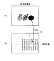
- the lighting device 400 includes a filter wheel 402, a motor 406 that rotationally drives the filter wheel 402, and a light source 408.
- the filter wheel 402 is provided with a plurality of wavelength filters (color filters) 404 for transmitting predetermined wavelength components.
- the specific wavelength filter 404 is set on the optical axis of the light source 408 as the motor 406 rotationally drives the filter wheel 402 in accordance with a command from the image processing apparatus 100.
- the light source 408 typically, a color rendering light source (standard light source) such as a halogen lamp or a xenon lamp is used.
- a color rendering light source standard light source
- light of the main wavelength corresponding to the selected wavelength filter 404 is emitted to the object OBJ.
- the image processing device 100 evaluates at which position on the color space it is out of the color gamut, The light to be emitted from the illumination device 400 to the object OBJ is switched based on the evaluation result (coordinate position).
- the color gamut that can be imaged by the imaging device 200 is determined according to the spectral sensitivity of the imaging element that constitutes the imaging device 200, the characteristics of the wavelength filter (color filter) 404 mounted on the filter wheel 402 It is preferable to determine according to the spectral sensitivity of the element.
- illumination apparatus 400 includes three wavelength filters 404 of R (red), G (green) and B (blue) as main wavelengths. That is, the lighting device 400 is configured to be able to switch and emit reddish illumination light, greenish illumination light, and bluish illumination light. Note that the illumination device 400 may emit light generated by the light source 408 as standard illumination light without passing through the wavelength filter 404 as described above.
- a plurality of illumination lights having different principal wavelengths can be selectively irradiated by using a color temperature conversion filter instead of, or together with the wavelength filter 404.
- a plurality of light sources whose main emission peaks are R (red), G (green) and B (blue) are disposed, and these light sources are selectively selected. It may be turned on.
- the spectral radiance meter 300 measures the spectral radiance (or spectral irradiance) of the illumination light emitted to the object OBJ, and outputs the measurement result to the image processing apparatus 100. This is a result of the imaging data of the object OBJ imaged by the imaging device 200 as a result of the illumination light irradiated to the object OBJ being reflected according to the spectral reflectance of the object OBJ, and the spectral reflection of the object OBJ This is because the spectral radiance of the illumination light emitted to the object OBJ is required to estimate the rate and perform color management.
- spectral radiance means the energy amount for every wavelength of illumination light per unit projected area and per unit solid angle.
- spectral irradiance which is the amount of energy per wavelength of illumination light per unit area, may be used.
- the spectral radiance meter 300 measures spectral radiance by receiving, at the light receiving unit, illumination light substantially the same as the illumination light irradiated to the object OBJ.
- the spectral radiance meter 300 is outside the imaging range of the imaging device 200 and is the same as the illumination environment of the object OBJ. It is preferable to arrange in the position which can be regarded as the lighting environment of Such an arrangement can be realized more easily by widening the irradiation range of the illumination light of the illumination device 400 as compared with the imaging range of the imaging device 200.
- a standard white plate having a known spectral reflectance at a position where the illumination light substantially the same as the illumination light irradiated to the object OBJ is irradiated The light reflected by the standard white plate may be received by the light receiving unit of the spectral radiance meter 300.
- the spectral radiance meter 300 includes, as its light receiving section, a diffraction grating, a photodiode array, and the like, and the photodiode array outputs a signal indicating the radiance for each wavelength. Furthermore, by mounting a milky white diffusion plate (also called a cosine collector, a cosine diffuser, or a cosine receptor) whose spectral transmittance is known to the light receiving portion, spatial brightness of light incident on the diffraction grating is obtained. As a result, it becomes possible to measure the spectral irradiance while reducing the unevenness (light and shade) of the light.
- a milky white diffusion plate also called a cosine collector, a cosine diffuser, or a cosine receptor
- the image processing apparatus 100 estimates the spectral reflectance of the object OBJ using the spectral radiance measured by the spectral radiance meter 300, and uses the estimated spectral reflectance to specify an image defined on the RGB color space.
- Data g i (m, n) is converted into image data g ′ XYZ (m, n) of the XYZ color system, and each image data g ′ XYZ (m, n) is in a color range that can be captured by the imaging device 200 Determine if it exists.
- any image data g ′ XYZ (m, n) exists outside the color gamut that can be imaged by the imaging device 200 a command is given to the illumination device 400 to switch the illumination environment for the object OBJ. Then, color reproduction data of the RGB colorimetric system is generated and output based on the imaging data g captured under an appropriate illumination environment.
- the image processing apparatus 100 includes a linear correction unit 102, a spectral reflectance estimation unit 130, a color conversion unit 134, coordinate conversion units 110 and 120, a gamma correction unit 122, and an evaluation unit 112.
- An evaluation table 114 and a primary storage unit 132 are included.
- the linear correction unit 102 is a part for linearizing the image data g output from the imaging device 200.
- a display device there is a non-linear relationship between an input signal level and an actually displayed luminance level, and such non-linearity is referred to as a gamma characteristic.
- Data g is often output.
- the signal level of the image data g and the luminance level detected by each imaging device are non-linear, the image processing described later can not be accurately performed, and thus the linear correction unit 102 This image data g is linearized.
- linear correction unit 102 when ⁇ c inverse gamma value in the image pickup apparatus 200, according to the following such calculation formula, image data g i Convert (m, n) into linearized linear image data gc i (m, n).
- the inverse gamma value ⁇ c is set to a value corresponding to the reciprocal of the gamma value ⁇ d of the display device.
- the image data g output from the imaging device 200 by one imaging operation is the same as the number of pixels of the imaging device 200. For example, when the pixels of the imaging device 200 are 1920 ⁇ 1080, The number is 2073600. Therefore, if the conversion equation as described above is executed as it is, the amount of calculation becomes enormous. If the processing capacity of the image processing apparatus 100 is sufficiently high, the calculation may be directly executed, but if there is a limit to the processing capacity, a Look-Up Table (LUT) is used. Is effective.
- LUT Look-Up Table
- the linear correction unit 102 stores the look-up table 102 a in advance, and performs linearization processing by referring to the look-up table 102 a.
- the look-up table 102a is a data table in which the result of the above-described conversion equation is stored in advance in association with each of all possible signal levels of the input image data g.
- the conversion amount corresponding to the signal level of the input image data g may be acquired with reference to the look-up table 102a, so the amount of operation can be significantly reduced.
- linear image data gc (1) i (m, n) and gc (2) i (m, n) are also collectively referred to as “linear image data gc”.
- the light (spectrum) from the object OBJ incident on the pixels of the two-dimensional coordinates (m, n) of the imaging device 200 is the spectral radiance E ( ⁇ ) of the illumination light irradiated to the object OBJ and the pixels of the object OBJ Corresponds to the product of the spectral reflectance f (m, n; ⁇ ) at the position corresponding to
- S i ( ⁇ ) which is the spectral sensitivity of each imaging element, and then, over the wavelength region It corresponds to the integration of light energy.
- n i (m, n) is additive noise generated by white noise or the like appearing in each imaging device, and is a value depending on the characteristics of the imaging device or lens of the imaging device 200 and the surrounding environment.
- the integral equation of the first term of the right side of equation (1) Is calculated by product-sum operation of discrete values obtained by sampling with a predetermined wavelength width. That is, the integral expression of the first term on the right side of the equation (1) is a matrix S indicating the spectral sensitivity at each wavelength of each imaging device, a matrix E indicating the spectral radiance at each wavelength, and a spectral reflectance at each wavelength It is realized by matrix operation with a matrix f (m, n) shown.
- the matrix S is a matrix of 401 rows ⁇ 3 columns
- the matrix E is a matrix of 401 rows ⁇ 1 columns
- the matrix f (m, n) is a matrix of 1 row ⁇ 401 columns.
- the spectral reflectance f (m, n) of the object OBJ is calculated after being ignored from the equation (1). Think about what to do. Specifically, using the linear image data gc, the spectral reflectance f (m, n) of the object OBJ is calculated according to the following equation (2).
- W is a spectral reflectance estimation matrix.
- the spectral reflectance estimation matrix W is calculated by the technique of Wiener estimation described below. Specifically, the spectral reflectance estimation matrix W is derived as the equation (4) by defining the system matrix H as the equation (3) shown below and modifying the equation (1).
- H S ⁇ E (3)
- W A ⁇ H t ⁇ (H ⁇ A ⁇ H t ) -1 (4)
- H t is the transpose of the system matrix H.
- A is an autocorrelation matrix, which should be a reference for estimating the spectral reflectance of the object OBJ.
- the autocorrelation matrix A can be determined in advance using statistical data of spectral reflectance that is considered to be equivalent to the object OBJ.
- autocorrelation matrix A can be determined with reference to SOCS (Standard Object Color Sample), which is a database of spectral reflectances standardized in International Organization for Standardization (ISO).
- SOCS Standard Object Color Sample
- ISO International Organization for Standardization
- the autocorrelation matrix A is a matrix of 401 rows ⁇ 1 column. Further, for details of the winner estimation, refer to “Mr. Yoichi Miyake,“ Introduction to spectral image processing ”, The University of Tokyo Press, February 24, 2006” above, for details.
- a principal component analysis method may be used instead of the above-described winner estimation method.
- the matrix f representing the spectral reflectance of the object OBJ from the linear image data gc according to the equation (2) m, n) can be calculated.
- the matrix f (m, n) is the essence of the color of the object OBJ, and by using this matrix f (m, n), the object OBJ can be observed under any illumination environment. Color reproduction can be performed.
- image processing apparatus 100 can generate color reproduction data gd of object OBJ when observed in an arbitrary illumination environment. More specifically, the tristimulus values X, Y, of the XYZ color system when an object of spectral reflectance f (m, n; ⁇ ) is observed under the condition of arbitrary spectral radiance E ( ⁇ ) Z becomes like (5) Formula shown below.
- the color matching function h i ( ⁇ ) is defined by the International Commission on Illumination (CIE).
- CIE International Commission on Illumination
- three-dimensional data including tristimulus values X, Y and Z calculated by the equation (5) will be expressed as image data g ′ XYZ (m, n).
- the matrix h is a matrix of 401 rows ⁇ 3 columns
- the matrix E is a matrix of 401 rows ⁇ 1 columns
- the matrix f (m, n) is a matrix of 1 row ⁇ 401 columns.
- image data g ′ XYZ (m, n) indicating the color of the object OBJ observed in an arbitrary illumination environment is expressed by equation (6).
- the matrix E indicating the spectral radiance used in the equation (6) can be set to any value. This means that the color of the subject OBJ to be observed when it is set to a different arbitrary illumination environment can be reproduced based on the image data g obtained by imaging the object OBJ under a certain illumination environment. Therefore, in order to reproduce the color of the object OBJ that would be observed under a specific illumination environment, it is not necessary to image the object OBJ under the specific illumination environment, but it is necessary to perform imaging under another illumination environment.
- imaging system 1 has an object of imaging object OBJ so as to be within a color range that can be imaged in imaging device 200.
- the spectral reflectance estimation unit 130 indicates the spectral radiance E measured by the spectral radiance meter 300 and the spectral sensitivity at each wavelength of the imaging device of the imaging device 200 stored in advance. Using the matrix S and the autocorrelation matrix A stored in advance, the matrix calculation of the equations (3) and (4) is executed to calculate the spectral reflectance estimation matrix W. Then, the spectral reflectance estimation unit 130 outputs the calculated spectral reflectance estimation matrix W to the color conversion unit 134.
- the cycle in which the spectral reflectance estimation unit 130 calculates the spectral reflectance estimation matrix W is the same as the imaging cycle in the imaging device 200, the measurement cycle of the spectral radiance by the spectral radiance meter 300 is imaged If it is later than the period, the spectral reflectance estimation matrix W may be calculated at the measurement period of the spectral radiance. Alternatively, when the illumination environment of the object OBJ hardly changes, the spectral reflectance estimation matrix W may be calculated only when the spectral radiance output from the spectral radiance meter 300 changes.
- the color conversion unit 134 includes the linear image data gc output from the linear correction unit 102, the spectral reflectance estimation matrix W output from the spectral reflectance estimation unit 130, and the spectral radiance measured by the spectral radiance meter 300.
- the matrix operation of the above equation (6) is executed using E and a matrix h indicating values of color matching functions at each wavelength stored in advance to calculate image data g ′ XYZ .
- a primary storage unit 132 is disposed between the spectral radiance meter 300 and the color conversion unit 134.
- the primary storage unit 132 temporarily stores the spectral radiance before switching when the evaluation unit 112 switches the illumination light from the illumination device 400 as described later, and the spectral radiance before switching is Function as a buffer for outputting to the color conversion unit 134. The detailed operation of the primary storage unit 132 will be described later.
- Coordinate conversion unit 120 converts 'the XYZ image data g of the RGB color system' image data g of the XYZ color system generated by the color conversion unit 134 into RGB, and outputs it to the gamma correction unit 122. That is, the coordinate conversion unit 120 converts the color space of the image data g ′ RGB and outputs it.
- the gamma correction unit 122 maintains the linearity of the RGB color system image data g ' RGB converted by the coordinate conversion unit 120. Therefore, when outputting to a display device or the like, the gamma characteristic of the display device In order to take account of this, it is necessary to perform correction in advance to cancel the gamma characteristic of the display device. That is, the gamma correction unit 122 performs conversion processing opposite to the conversion processing in the linear correction unit 102.
- the gamma correction unit 122 performs color reproduction data gd RGB on the image data g ′ RGB (m, n) of the RGB colorimetric system according to the following arithmetic expression using the gamma value ⁇ d of the display device: Convert to (m, n).
- gd RGB (m, n) g ' RGB (m, n) ⁇ d
- the gamma value ⁇ d of the display device is set to “2.2” or the like as an example.
- the gamma correction unit 122 performs arithmetic processing using a look-up table (LUT). More specifically, the gamma correction unit 122 stores the look-up table 122a in advance, and performs gamma correction processing by referring to the look-up table 122a.
- the look-up table 122a is a data table in which the result of the above-mentioned conversion equation is stored in advance in association with each of all possible signal levels of the input image data g ′ RGB . In the actual linearization operation, the conversion amount corresponding to the input image data g ′ RGB signal level may be acquired with reference to the look-up table 122 a, so the amount of operation can be significantly reduced.
- the contents of the look-up table 122a differ depending on the gamma value ⁇ d, when the gamma value ⁇ d is changed, the contents of the look-up table 122a also need to be changed.
- the evaluation unit 112 evaluates whether or not the image data g captured by the imaging device 200 is captured within the imageable color range of the imaging device 200 in the process of generating the color reproduction data gd as described above. Do. Then, when the evaluation unit 112 evaluates that the image data g includes a color outside the imageable color range, the lighting device may be configured such that the color emitted by the object OBJ falls within the imageable color range of the imaging device 200. A specific illumination light is emitted from 400. Since it is necessary to evaluate whether or not it is in such a color range in the color space of the XYZ color system, the evaluation unit 112 evaluates the image data g ′ XYZ output from the color conversion unit 134. Do.
- FIG. 2 is a diagram for explaining an outline of the color gamut evaluation process in the evaluation unit 112 shown in FIG.
- tristimulus values X, Y and Z of the XYZ color system are defined by two variables x and y obtained by the conversion equations as shown in equations (7) and (8). It can be expressed as two-dimensional coordinates (hereinafter also referred to as "xy coordinates").
- FIG. 2 shows a chromaticity diagram in the XYZ color system.
- this chromaticity diagram it means that the center is white, and as it goes to the outer periphery, it is a color whose "purity" is higher.
- B (blue), G (green) and R (red) are mainly located at each vertex of the substantially triangular shape.
- the imageable color gamut of the imaging device 200 including three imaging elements of R, G, and B has colors (purity) detectable by each imaging element in xy coordinates. It will be a triangle to be a vertex. When the number of imaging elements (the number of bands) is increased, the number of polygons is the same as the number of bands.
- each pixel of the imaging device 200 under the first illumination environment is illustrated as a sample point.
- Each sample point is obtained by plotting the image data g ′ (1) XYZ of each pixel calculated by the above-described color reproduction process on xy coordinates.
- the color of the sample point outside the color gamut is falsely detected (clipped) as a color within the color gamut closest to the imageable color gamut. That is, a color present outside the imageable color gamut is detected as another color whose purity is lowered.
- the colors of the two sample points shown in FIG. 2A are originally relatively high in purity yellow, but are detected as more reddish.
- the spectral reflectance can not be accurately calculated in the above-described color reproduction process. As a result, color reproduction can not be performed accurately.
- the light (color) emitted from the object OBJ changes according to the illumination environment, so by switching the illumination environment appropriately, sample points existing outside the imageable color gamut can be captured within the imageable color range It can be paid.
- FIG. 2B is a diagram showing sample points in the case where an object OBJ similar to that of FIG. 2A is imaged in a more bluish illumination environment.
- each sample point moves in the blue direction (lower left direction on the xy coordinates) in xy coordinates as a whole. That is, by changing the illumination environment, sample points existing outside the color gamut in FIG. 2A (that is, points having a relatively high purity yellow) emit a yellow having a lower purity.
- the image can be captured within the imageable color range of the imaging device 200.
- the entire object OBJ can be imaged within the color range which can be imaged by the imaging device 200, the spectral reflectance of the object OBJ can be accurately estimated.
- FIG. 2 (C) generated color reproduction data gd which should have been generated under the illumination environment of FIG. 2 (A) based on the imaging data imaged under the illumination environment of FIG. 2 (B) Indicates the case.
- evaluation unit 112 evaluates at which position on the xy coordinates the color is out of the color gamut, and selects the illumination light according to this position.
- FIG. 3 is a view for explaining an outline of switching processing of illumination light in the evaluation unit 112 shown in FIG.
- the coordinates corresponding to the red of the maximum purity that can be imaged by the R imaging device is (x1, y1), and corresponds to the green of the maximum purity that can be imaged by the G imaging device
- the evaluation unit 112 evaluates at which position on the xy coordinate the color included in the image data g ′ (1) is out of the color gamut, and selects the illumination light according to the position.
- coordinate conversion unit 110 converts the respective components of image data g ′ sequentially output from color conversion unit 134 into the conversion equations shown in the above-mentioned equations (7) and (8). Perform coordinate transformation according to. Then, the coordinate conversion unit 110 sequentially outputs the converted coordinate values (x, y) to the evaluation unit 112.
- the evaluation unit 112 stores coordinate values (x, y) sequentially output from the coordinate conversion unit 110 by the number corresponding to one imaging by the imaging device 200, and the imaging device 200 defined in advance on xy coordinates. It is determined whether or not there is something outside the color gamut that can be imaged. Note that the color gamut that can be imaged by the imaging device 200, which is defined in advance on the xy coordinates, is stored in advance in the evaluation table 114. Further, since the color gamut that can be imaged by the imaging device 200 depends on the characteristics of the imaging elements that constitute the imaging device 200, the type or individual of the imaging device 200 is acquired in advance by experiment or simulation.
- the evaluation unit 112 detects that the coordinate value (x, y) exists outside the color gamut that can be captured by the imaging device 200. y) Evaluate at which position the color gamut is out. Then, the evaluation unit 112 outputs a selection command of the illumination light to the lighting device 400 according to the position. As described above, specifically, the evaluation unit 112 determines whether the coordinate value (x, y) exists in any linear region connecting the respective coordinates corresponding to R, G, B on the xy coordinates. Judging by
- the evaluation unit 112 maintains the output of the spectral radiance at the relevant time point (before switching of the illumination light) to the primary storage unit 132. Give a command to This is to allow the color conversion unit 134 to output the image data g ′ that should have been captured under the illumination environment before switching (that is, under the original illumination environment).
- the evaluation unit 112 is controlled to calculate the image data g ′.
- the evaluation unit 112 performs coordinate conversion in the coordinate conversion unit 120 when none of the coordinate values (x, y) output from the coordinate conversion unit 110 exists outside the color gamut that can be captured by the imaging device 200. While giving a command for validating the process, if there is one that exists outside the color gamut that can be captured by the imaging device 200, a command for invalidating the coordinate conversion processing in the coordinate conversion unit 120 is given. This is to prevent output of low-reliability color reproduction data gd generated based on image data including colors outside the color gamut that can be imaged by the imaging device 200.
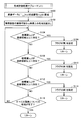
- FIG. 4 is a flowchart showing the overall processing procedure in the imaging system 1 according to the first embodiment of the present invention.
- FIG. 5 is a flowchart showing the contents of the color gamut evaluation processing subroutine (1) shown in FIG.
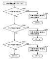
- FIG. 6 is a flowchart showing the contents of the lighting environment switching subroutine shown in FIG.
- superscript (1) data etc. obtained by the first imaging are indicated by superscript (1) and obtained by the second imaging Data and the like are indicated with superscript (2) .
- imaging device 200 captures an object OBJ, and outputs imaging data g (1) according to object OBJ (step S2).
- the imaging device 200 performs an imaging operation in response to an operation by a user or the like.
- the spectral reflectance estimation unit 130 acquires the spectral radiance E (1) measured by the spectral radiance meter 300 (step S4), and calculates the spectral reflectance estimation matrix W (1) (step S6). ).
- the linear correction unit 102 linearizes the image data g (1) i (m, n) corresponding to one pixel output from the imaging device 200 to generate linear image data gc (1) i (m, n ). ) Is generated (step S8). Then, the color conversion unit 134 outputs the spectral radiance E (1) acquired in step S4, the spectral reflectance estimation matrix W (1) calculated in step S6, and the linear image data gc generated in step S8.
- Image data g ' (1) XYZ (m, n) is calculated using i (m, n) (step S10). Furthermore, it is determined whether the processing for all the pixels included in the imaging data g (1) is completed (step S12), and the processing for all the pixels is not completed (NO in step S12), The processes after step S8 are executed again.
- step S12 image data g ' (1) XYZ (m, n) exists in a color range that can be captured by imaging device 200.
- step S14 In order to evaluate whether or not the color gamut evaluation processing subroutine (1) is executed (step S14). As described later, when the evaluation result of the color gamut evaluation processing subroutine (1) in step S14 is output as a "flag" to a memory area provided in the evaluation unit 112 or the like, and the flag is set, This means that the image data g ′ (1) XYZ (m, n) exist outside the color gamut that can be imaged by the imaging device 200.
- the evaluation unit 112 determines whether any flag is set, that is, the image data g ′ (1) XYZ (outside the color gamut that can be imaged by the imaging device 200 ). It is determined whether m, n) exists (step S16). When the flag is set (in the case of YES in step S16), the evaluation unit 112 stores the current spectral radiance E (1) in the primary storage unit 132 (step S18) and from the lighting device 400 In order to switch the illumination light, the illumination environment switching subroutine is executed (step S20).
- the imaging device 200 After execution of the illumination environment switching subroutine, the imaging device 200 captures an image of the object OBJ again, and outputs imaging data g (2) according to the object OBJ (step S22). Subsequently, the spectral reflectance estimation unit 130 acquires the spectral radiance E (2) measured by the spectral radiance meter 300 (step S24), and calculates the spectral reflectance estimation matrix W (2) (step S26). ).
- the linear correction unit 102 linearizes the image data g (2) i (m, n) corresponding to one pixel output from the imaging device 200 to generate linear image data gc (2) i (m, n ). ) Is generated (step S30). Then, the color conversion unit 134 generates the spectral radiance E (1) stored in the primary storage unit 132 in step S18, the spectral reflectance estimation matrix W (2) calculated in step S26, and the signal generated in step S30. Image data g ' (2) XYZ (m, n) is calculated using linear image data gc (2) i (m, n) (step S32). Further, it is determined whether or not processing for all pixels included in imaging data g (2) is completed (step S34), and processing for all pixels is not completed (NO in step S34) The process after step S30 is executed again.
- step S34 coordinate conversion unit 120 converts image data g ′ (2) XYZ (m, n) calculated in step S32 RGB color system image data g ′ RGB (m, n) is converted (step S 54), and then the gamma correction unit 122 converts the image data g ′ RGB (m, n) into color reproduction data gd RGB (m , N) (step S56) and externally output.
- the coordinate conversion unit 120 converts the image data g ′ (1) XYZ (m, n) calculated in step S10 into the RGB color system
- the image data g ′ RGB (m, n) is converted into the image data g ′ RGB (m, n) (step S 58).
- the gamma correction unit 122 converts the image data g ′ RGB (m, n) into color reproduction data gd RGB Convert (step S60), and output it to the outside.
- step S14 the contents of the color gamut evaluation processing subroutine (1) of step S14 will be described.
- coordinate conversion unit 110 converts image data g ′ (1) XYZ (m, n) into coordinate values (x, y) on xy coordinates (step S100).
- the evaluation unit 112 reads the color gamut on the imageable xy coordinates of the imaging device 200 from the evaluation table 114 (step S102).
- the evaluation unit 112 corresponds to the coordinates (x1, y1) and G (green) corresponding to R (red) as shown in FIG. 3 as the coordinate values (x, y) calculated in step S100 It is determined whether it exists on a straight line area (a) connecting x2, y2) (step S104). If the coordinate value (x, y) exists on the linear area (a) (YES in step S104), the evaluation unit 112 sets a flag B (blue) (step S106).
- the evaluation unit 112 calculates the coordinate value (x, y) calculated in step S100 as shown in FIG. It is determined whether or not it exists on a linear region (b) connecting the coordinates (x2, y2) corresponding to G (green) and (x3, y3) corresponding to B (blue) as shown in FIG. Step S108). If the coordinate value (x, y) exists on the linear region (b) (YES in step S108), the evaluation unit 112 sets a flag R (red) (step S110).
- the evaluation unit 112 calculates the coordinate value (x, y) calculated in step S100 as shown in FIG. It is determined whether it exists on a straight line area (c) connecting the coordinates (x3, y3) corresponding to B (blue) and (x1, y1) corresponding to R (red) as shown in FIG. Step S112). If the coordinate value (x, y) exists on the linear region (c) (YES in step S112), the evaluation unit 112 sets a flag G (green) (step S114).
- step S116 it is determined whether or not processing for all pixels included in imaging data g (1) is completed (step S116), and processing for all pixels is not completed (NO in step S116) The process after step S100 is executed again.
- step S116 if the process for all the pixels is completed (YES in step S116), the process proceeds to step S16 in FIG.
- evaluation unit 112 first determines whether flag B (blue) is set (step S200). When flag B (blue) is set (YES in step S200), evaluation unit 112 causes illumination light including a large amount of B (blue) component to be emitted from illumination device 400 toward object OBJ. (Step S202).
- evaluation unit 112 determines whether flag R (red) is set (step S204). When the flag R (red) is set (YES in step S204), illumination light including a large amount of R (red) component is emitted from the illumination device 400 toward the object OBJ (step S206).
- the evaluation unit 112 determines whether the flag G (green) is set (step S208). If the flag G (green) is set (YES in step S208), illumination light including a large amount of G (green) components is emitted from the illumination device 400 toward the object OBJ (step S210).
- the first embodiment of the present invention it is possible to determine the illumination environment at the time of imaging the subject in consideration of the color gamut that can be imaged by the imaging device. Therefore, since the color of the subject can be correctly captured using the imaging device, the spectral reflectance of the subject can be accurately estimated from the captured imaging data. Therefore, even if the color of the subject exists outside the imageable color gamut of the imaging device in the illumination environment where the subject should be imaged, the illumination environment where the imaging should be performed after the spectral reflectance is accurately estimated. The color that will be imaged (observed) can be properly reproduced.
- the display device can also display a color of purity exceeding the imaging capability of the imaging device. It becomes.
- FIG. 7 is a schematic block diagram of an imaging system 2 according to the second embodiment of the present invention.
- imaging system 2 images subject OBJ as in imaging system 1 according to the first embodiment, and performs predetermined image processing (mainly, color reproduction processing) on the imaged image data. After the output, image data (color reproduction data) is output. More specifically, in the imaging system 1 according to the first embodiment, the imaging system 2 employs the image processing apparatus 100A in place of the image processing apparatus 100, and the imaging system 1 is used for the other parts. And the detailed description will not be repeated.
- the illumination device 400 emits illumination light to the object OBJ when the imaging device 200 captures an image of the object OBJ.
- illumination apparatus 400 according to the present embodiment is configured to be able to selectively emit a plurality of illumination lights having different principal wavelengths toward object OBJ in accordance with an instruction from image processing apparatus 100A. That is, as described later, as a result of imaging the object OBJ in a predetermined illumination environment (hereinafter also referred to as “first illumination environment”), the imaging data includes pixels having colors outside the color range that can be imaged by the imaging device 200.
- the illumination device 400 When it is determined that the illumination light is emitted, the illumination device 400 emits another illumination light to the object OBJ so that the color of the pixel falls within the color range that can be captured by the imaging device 200.
- the illumination light from the illumination device 400 forms an illumination environment (hereinafter also referred to as a “second illumination environment”) different from the first illumination environment.
- the image processing apparatus 100A when a pixel having a color outside the color gamut that can be imaged by the imaging device 200 is included in the imaging data, the pixel is out of the color gamut at any position on the color space. It is evaluated whether it has become, and the light emitted from the illumination device 400 to the object OBJ is switched based on the evaluation result (coordinate position).
- the color gamut that can be imaged by the imaging device 200 is determined according to the spectral sensitivity of the imaging element that constitutes the imaging device 200, the characteristics of the wavelength filter (color filter) 404 mounted on the filter wheel 402 It is preferable to determine according to the spectral sensitivity of the element.
- illumination apparatus 400 includes three wavelength filters 404 of R (red), G (green) and B (blue) as main wavelengths. That is, the lighting device 400 is configured to be able to switch and emit reddish illumination light, greenish illumination light, and bluish illumination light. In order to form the first illumination environment, the light generated by the light source 408 may be irradiated as it is without passing through such a wavelength filter 404.
- the image processing apparatus 100A uses the imaging data g (1) obtained by imaging the object OBJ under the first illumination environment and the spectral radiance E (1) measured under the first illumination environment to generate the object OBJ in each pixel. After the spectral reflectance is estimated, imaging data g (1) i (m, n) defined on the RGB color space is XYZ using the estimated spectral reflectance and the spectral radiance E (1). Image data of color system g ′ (1) Convert to XYZ (m, n).
- the image processing apparatus 100A determines whether the image data g ′ (1) XYZ (m, n) exist in a color range that can be captured by the imaging device 200. If any image data g ′ (1) XYZ (m, n) exists outside the color gamut that can be imaged by the imaging device 200, the second illumination environment is irradiated by irradiating a specific illumination light from the illumination device 400. Form.
- the image processing apparatus 100A uses the imaging data g (2) obtained by imaging the object OBJ under the second illumination environment and the spectral radiance E (2) measured under the second illumination environment, and the object at each pixel Image data g (2) i (m, n) defined on the RGB color space by using the estimated spectral reflectance and spectral radiance E (1) after estimating the spectral reflectance of OBJ Is converted to image data g ′ of XYZ color system (2) XYZ (m, n).
- the image processing apparatus 100A uses the corresponding image data g ′ (1) XYZ (m, n) for the pixels existing in the color range that can be imaged by the imaging device 200, and the remaining pixels, ie, the imaging device For pixels existing outside the color gamut that can be imaged at 200, composite image data G XYZ (m, n) is synthesized using the corresponding image data g ' (2) XYZ (m, n). Then, based on the composite image data G XYZ (m, n), color reproduction data of the RGB color system is generated and output.
- the image processing apparatus 100A can capture an image with the imaging device 200.
- composite image data G XYZ (m, n) is generated.
- the image processing apparatus 100A includes a linear correction unit 102A, a first color conversion unit 104, a second color conversion unit 106, coordinate conversion units 110 and 120, an evaluation unit 112A, an evaluation table 114, and the like. , A combining unit 116, a flag table 118, and a gamma correction unit 122.
- the linear correction unit 102A is a unit for linearizing the imaging data g output from the imaging device 200.
- a display device there is a non-linear relationship between an input signal level and an actually displayed luminance level, and such non-linearity is referred to as a gamma characteristic.
- Data g is often output.
- the signal level of the imaging data g and the luminance level detected by each imaging device are non-linear, the image processing to be described later can not be accurately performed, and thus the linear correction unit 102A This imaging data g is linearized.
- the gamma characteristic and the inverse gamma characteristic can be expressed as a function of a power, and therefore, assuming that the inverse gamma value in the imaging device 200 is ⁇ c, the linear correction unit 102A sets imaging data g ( 1) i (m, n) or g (2) i (m, n) the linear image data gc which is respectively linearized (1) i (m, n ) or gc (2) i (m, n) Convert to
- the inverse gamma value ⁇ c is set to a value corresponding to the reciprocal of the gamma value ⁇ d of the display device.
- the imaging data g (1) i (m, n) and g (2) i (m, n) output from the imaging device 200 by one imaging exist for the number of pixels of the imaging device 200.
- the number of imaging data g (1) i (m, n) and g (2) i (m, n) is all 2073600. . Therefore, if the conversion equation as described above is executed as it is, the amount of calculation becomes enormous. If the arithmetic processing capability of the image processing apparatus 100A is sufficiently high, the arithmetic may be directly executed, but it is effective to use a look-up table (LUT) when the arithmetic processing capability is limited. .
- LUT look-up table
- the linear correction unit 102A stores the look-up table 102a in advance, and performs linearization processing by referring to the look-up table 102a.
- the look-up table 102a is a data table in which the result of the above-described conversion equation is stored in advance in association with each of all the signal levels that can be acquired by the input imaging data g.
- the conversion amount corresponding to the signal level of the input imaging data g may be acquired with reference to the look-up table 102a, so the amount of operation can be significantly reduced.
- the main contents of the color reproduction process performed by the color conversion unit 104 and the spectral reflectance estimation unit 110 are the color conversion unit 134 and the spectral reflectance estimation unit 130 in the image forming apparatus 100 according to the first embodiment described above. As this is similar to the color reproduction process to be performed, the detailed description will not be repeated.
- the matrix E indicating the spectral radiance used in the above equation (6) can be set to an arbitrary value. This is observed under the first illumination environment (spectral radiance E (1) ) based on imaging data g (2) obtained by imaging the object OBJ under the second illumination environment (spectral radiance E (2) ) It means that the color of the object OBJ can be reproduced. Therefore, in order to reproduce the color of the object OBJ to be observed under the first illumination environment, it is not necessary to image the object OBJ under the first illumination environment, but it is necessary to perform imaging under another second illumination environment. It means that the captured image data g (2) may be used.
- imaging system 2 has an object of imaging object OBJ so as to be within the imageable color range in imaging device 200.
- the first color conversion unit 104 is a part for generating the image data g ′ (1) from the imaging data gc (1) imaged under the first illumination environment, and It includes a reflectance estimation unit 104a and a color reproduction unit 104b.
- the spectral reflectance estimation unit 104a indicates the spectral radiance E (1) measured by the spectral radiance meter 300 under the first illumination environment and the spectral sensitivity at each wavelength of the imaging device of the imaging device 200 stored in advance. Using the matrix S and the autocorrelation matrix A stored in advance, the matrix operation of the above equations (3) and (4) is executed to calculate a spectral reflectance estimation matrix W (1) . Then, the spectral reflectance estimation unit 104a outputs the calculated spectral reflectance estimation matrix W (1) to the color reproduction unit 104b.
- the cycle in which the spectral reflectance estimation unit 104 a calculates the spectral reflectance estimation matrix W is the same as the imaging cycle in the imaging device 200, the measurement cycle of the spectral radiance by the spectral radiance meter 300 is imaged If it is later than the period, the spectral reflectance estimation matrix W may be calculated at the measurement period of the spectral radiance. Alternatively, when the illumination environment of the object OBJ hardly changes, the spectral reflectance estimation matrix W may be calculated only when the spectral radiance output from the spectral radiance meter 300 changes.
- the color reproduction unit 104 b includes the linear image data gc (1) output from the linear correction unit 102 A, the spectral reflectance estimation matrix W (1) output from the spectral reflectance estimation unit 104 a, and the spectral radiance meter 300. Using the measured spectral radiance E (1) and the matrix h indicating the value of the color matching function at each wavelength stored in advance, the matrix operation of the above equation (6) is executed, and the image data g ′ ( 1) Calculate XYZ .
- the second color conversion unit 106 when the second illumination environment is changed from the first illumination environment to the second illumination environment as described later, the second color conversion unit 106 generates an image from the imaging data gc (2) imaged under the second illumination environment A portion for generating data g ′ (2) , which includes a spectral reflectance estimation unit 106 a and a color reproduction unit 106 b.
- the spectral reflectance estimation unit 106a includes the spectral radiance E (2) measured by the spectral radiance meter 300 under the second illumination environment, and the imaging device 200 stored in advance.
- the spectral reflectance estimation matrix W (2) is calculated using the matrix S indicating the spectral sensitivity at each wavelength of the imaging device and the autocorrelation matrix A stored in advance. Then, the spectral reflectance estimation unit 106a outputs the calculated spectral reflectance estimation matrix W (2) to the color reproduction unit 106b.
- the color reproduction unit 106 b includes the linear image data gc (2) output from the linear correction unit 102 A, the spectral reflectance estimation matrix W (2) output from the spectral reflectance estimation unit 106 a, and the first illumination environment.
- Image data g ′ (2) XYZ is calculated using the spectral radiance E (1) measured by the spectral radiance meter 300 and the matrix h indicating the value of the color matching function at each wavelength stored in advance. .
- the combining unit 116 selects a specific one of the pixel data included in the image data g ′ (1) XYZ and the pixel data included in the image data g ′ (2) XYZ according to the map data of the flag table 118 described later. Are combined with a specific one of them to generate composite image data G.sub.XYZ .
- Coordinate conversion unit 120 the synthetic image data G XYZ of the XYZ color system generated by the synthesis unit 116 converts the synthesized image data G RGB in the RGB color system, and outputs it to the gamma correction unit 122. That is, the coordinate conversion unit 120 converts the color space of the composite image data G RGB and outputs the result.
- the gamma correction unit 122 performs conversion processing reverse to the conversion processing in the linear correction unit 102A. More specifically, the gamma correction unit 122 performs the color reproduction data gd RGB on the composite image data G RGB (m, n) of the RGB color system according to the following arithmetic expression using the gamma value ⁇ d of the display device. Convert to (m, n).
- gd RGB (m, n) G RGB (m, n) ⁇ d
- the gamma value ⁇ d of the display device is set to “2.2” or the like as an example.
- the gamma correction unit 122 performs arithmetic processing using a look-up table (LUT). More specifically, the gamma correction unit 122 stores the look-up table 122a in advance, and performs gamma correction processing by referring to the look-up table 122a.
- the look-up table 122a is a data table in which the result of the above-described conversion equation is stored in advance in association with each of all possible signal levels of the input composite image data G RGB . In the actual linearization operation, the conversion amount corresponding to the signal level of the input composite image data G RGB may be acquired with reference to the look-up table 122a, so the amount of operation can be significantly reduced.
- the contents of the look-up table 122a differ depending on the gamma value ⁇ d, when the gamma value ⁇ d is changed, the contents of the look-up table 122a also need to be changed.
- the evaluation unit 112A determines whether the imaging data g (1) imaged under the first illumination environment is within a color range that can be imaged by the imaging device 200. evaluate. Then, when the evaluation unit 112A evaluates that the imaging data g (1) includes a color outside the color gamut that can be imaged by the imaging device 200, the color emitted by the object OBJ is within the color range that can be imaged by the imaging device 200.
- the illumination device 400 emits specific illumination light to form a second illumination environment. Since it is necessary to evaluate the presence or absence in such a color gamut in the color space of the XYZ color system, the evaluation unit 112A determines that the image data g ′ (1 ) Evaluate XYZ .
- the color gamut evaluation process in evaluation unit 112A is the same as the color gamut evaluation process in evaluation unit 112 of image forming apparatus 100 according to the first embodiment described above, and therefore detailed description will not be repeated.
- each sample point moves in the blue direction (lower left direction on the xy coordinates) in xy coordinates as a whole. . That is, by changing the illumination environment, the sample point (hereinafter also referred to as “correction target”) existing outside the color gamut in FIG. 2A emits yellow having a lower purity. It falls within the imageable color range of the device 200. As a result, the color of the portion corresponding to the correction target of the object OBJ can be captured within the imageable color range of the imaging device 200.
- Image data corresponding to imaging data g (1) which should have been imaged under the first illumination environment from imaging data g (2) imaged under the second illumination environment as shown in the above-mentioned equation (6) g ' (2) can generate XYZ . Therefore, while using the image data g ' (2) XYZ generated from the imaging data g (2) captured under the second illumination environment for the pixels to be corrected, the first illumination environment is used for the remaining pixels.
- the color reproduction data gd can be generated by using the image data g ′ (1) XYZ generated from the imaging data g (1) picked up below.
- FIG. 2C should be generated under the first illumination environment shown in FIG. 2A based on the imaging data g (2) imaged under the second illumination environment shown in FIG. 2B. The case where the image data g ' (2) XYZ which had been generated is generated is shown. By performing such color reproduction processing, even if the color is out of the color gamut that can be imaged by the imaging device 200, color reproduction can be performed accurately.
- FIG. 8 is a diagram for describing an outline of the image combining process according to the present embodiment.
- a portion (correction target) having a color that is out of the color gamut that can be imaged by imaging device 200 is specified.
- the image pickup data g (1) image data g of a portion excluding the corrected generated from '(1), the correction object generated from the captured imaged data g (2) in the second illumination environment
- the image data g ′ (2) of the corresponding part is synthesized and generated as synthesized image data G.
- evaluation unit 112A evaluates at which position on the xy coordinates the color is out of the color gamut, and selects the illumination light according to this position.
- the switching process of the illumination light in evaluation unit 112A is the same as the switching process of the illumination light in evaluation unit 112 of image forming apparatus 100 according to the first embodiment described above, and therefore detailed description will not be repeated.
- the evaluation unit 112A stores coordinate values (x, y) sequentially output from the coordinate conversion unit 110 by the number corresponding to one imaging by the imaging device 200, and the imaging device 200 defined in advance on xy coordinates. It is determined whether or not there is something outside the color gamut that can be imaged. Then, when there is a pixel having a color existing outside the color gamut that can be captured by the imaging device 200, the evaluation unit 112A stores information (flag) for specifying the position of the pixel in the flag table 118. . That is, the evaluation unit 112A classifies pixels having colors present in a color gamut that can be imaged by the imaging device 200 and pixels that have colors present outside the color gamut that can be imaged by the imaging device 200.
- the evaluation unit 112A determines at which position the coordinate value (x, y) falls outside the color gamut. evaluate. Then, the evaluation unit 112A outputs a selection command of the illumination light to the illumination device 400 according to the position. As described above, specifically, the evaluation unit 112A determines whether the coordinate value (x, y) exists in any linear region connecting the respective coordinates corresponding to R, G, B on the xy coordinates. Judging by
- the color gamut that can be imaged by the imaging device 200 which is defined in advance on the xy coordinates, is stored in advance in the evaluation table 114. Further, since the color gamut that can be imaged by the imaging device 200 depends on the characteristics of the imaging elements that constitute the imaging device 200, the type or individual of the imaging device 200 is acquired in advance by experiment or simulation.
- FIG. 9 is a diagram for explaining the data structure stored in flag table 118 shown in FIG.
- the flag table 118 according to the present embodiment has a data structure corresponding to the pixel arrangement (for example, 1920 ⁇ 1080 pixels) in the imaging device 200.
- the initial values of the flag table 118 are all set to "0".
- the evaluation unit 112A selects pixels having colors that exist outside the color gamut that can be imaged by the imaging device 200 among the imaging data g ′ (1) imaged in the first illumination environment.
- the flag of the position corresponding to the pixel in the flag table 118 is set to “1”.
- the evaluation unit 112A performs the above-described process on all the pixels included in the imaging data g ′ (1) .
- a map is formed which shows, among the pixels captured by the imaging device 200, those whose colors exist outside the color gamut that can be captured by the imaging device 200.
- the synthesizing unit 116 specifies the image data g ′ (2) necessary for generating the synthesized image data G with reference to the map formed in the flag table 118 as described above.
- the second color conversion unit 106 may calculate the image data g ′ (2) corresponding to all the pixels based on the imaging data g (2) captured under the second illumination environment.
- the calculation processing of the image data g ′ (2) has a relatively large amount of operation, referring to the flag table 118 via the combining unit 116, only the pixels necessary for generating the combined image data G It is preferable to generate data g ′ (2) .
- the color is specified in addition to information for specifying a pixel having a color that is out of the color gamut that can be captured by the imaging device 200 among the imaging data g ′ (1). You may store information for
- FIG. 10 is a view showing another form of the flag table 118 shown in FIG. Referring to FIG. 10, in the flag table 118 of this embodiment, “R”, “G”, and “B” for specifying the color at the position corresponding to the pixel having the color existing outside the imageable color gamut. Values such as are stored.
- R”, “G”, and “B” for specifying the color at the position corresponding to the pixel having the color existing outside the imageable color gamut. Values such as are stored.
- FIG. 11 is a flowchart showing the overall processing procedure in the imaging system 2 according to the second embodiment of the present invention.
- FIG. 12 is a flowchart showing the contents of the color gamut evaluation processing subroutine (2) shown in FIG.
- imaging device 200 captures an object OBJ in the first illumination environment, and outputs imaging data g (1) according to object OBJ (step S2).
- the imaging device 200 performs an imaging operation in response to an operation by a user or the like.
- the spectral reflectance estimation unit 104a acquires the spectral radiance E (1) measured by the spectral radiance meter 300 (step S4), and calculates the spectral reflectance estimation matrix W (1) (step S6). ).
- the linear correction unit 102A linearizes the imaging data g (1) i (m, n) corresponding to one pixel output from the imaging device 200 to generate linear image data gc (1) i (m, n ). ) Is generated (step S8). Then, the color reproduction unit 104b uses the spectral radiance E (1) acquired in step S4, the spectral reflectance estimation matrix W (1) calculated in step S6, and the linear image data gc generated in step S8. (1) Image data g ' (1) XYZ (m, n) is calculated using i (m, n) (step S10). Furthermore, it is determined whether the processing for all the pixels included in the imaging data g (1) is completed (step S12), and the processing for all the pixels is not completed (NO in step S12), The processes after step S8 are executed again.
- step S12 image data g ' (1) XYZ (m, n) exists in a color range that can be captured by imaging device 200.
- step S14 The evaluation result of the color gamut evaluation processing subroutine (2) is stored in the flag table 118.
- the evaluation unit 112A determines whether the flag is set in the flag table 118, that is, the image data g ′ (1) XYZ (outside the color gamut that can be imaged by the imaging device 200 ). It is determined whether m, n) exists (step S16). When the flag is set (YES in step S16), the color reproduction unit 106b stores the spectral radiance E (1) at the present time (step S18). Then, the evaluation unit 112A executes a lighting environment switching subroutine in order to switch the illumination light from the lighting device 400 (step S20).
- the imaging device 200 After execution of the illumination environment switching subroutine, the imaging device 200 images the object OBJ again under the second illumination environment, and outputs imaging data g (2) according to the object OBJ (step S22). Subsequently, the spectral reflectance estimation unit 106a acquires the spectral radiance E (2) measured by the spectral radiance meter 300 (step S24), and calculates the spectral reflectance estimation matrix W (2) (step S26). ).
- the evaluation unit 112A refers to the flag table 118 to specify pixels necessary for generating the composite image data G (step S28).
- the linear correction unit 102A linearizes g (2) i (m, n) corresponding to the pixels necessary for the composite image data G out of the imaging data g (2) output from the imaging device 200 and generates linear image data.
- gc (2) i (m, n) is generated (step S30).
- the color reproduction unit 106b stores the spectral radiance E (1) stored in advance in step S18, the spectral reflectance estimation matrix W (2) calculated in step S26, and the linear image data gc generated in step S30.
- step S32 Image data g ' (2) XYZ (m, n) is calculated using i (m, n) (step S32). Furthermore, it is judged whether or not processing for all pixels necessary for composite image data G is completed (step S34), and processing for all pixels necessary for composite image data G is not completed (step S34) The process of step S28 and subsequent steps is executed again.
- combining unit 116 calculates the image data g ′ calculated in step S32 (2) XYZ (M, n) and data excluding the pixel corresponding to the image data g ′ (2) XYZ (m, n) among the image data g ′ (1) XYZ (m, n) calculated in step S 10
- the composite image data G XYZ are generated from (step S36).
- the coordinate conversion unit 120 converts the synthesized image data G XYZ calculated in step S36 in the composite image data G RGB in the RGB color system (step S38), followed by gamma correction unit 122, the synthetic image data G RGB is converted to color reproduction data gd RGB (step S40), and output to the outside.
- the combining unit 116 combines the image data g ′ (1) XYZ (m, n) calculated in step S10 with the combined image data G XYZ Output (step S42). Furthermore, the coordinate conversion unit 120 converts the synthesized image data G XYZ output in step S40 in the composite image data G RGB in the RGB color system (step S44), followed by gamma correction unit 122, the synthetic image data G RGB is converted to color reproduction data gd RGB (step S46), and output to the outside.
- coordinate conversion unit 110 converts image data g ′ (1) XYZ (m, n) into coordinate values (x, y) on xy coordinates (step S100). Then, the evaluation unit 112A reads the color gamut on the imageable xy coordinates of the imaging device 200 from the evaluation table 114 (step S102).
- the coordinate values (x, y) calculated in step S100 correspond to the coordinates (x1, y1) and G (green) corresponding to R (red) as shown in FIG. It is determined whether it exists on a straight line area (a) connecting x2, y2) (step S104). If the coordinate value (x, y) exists on the linear area (a) (YES in step S104), the evaluation unit 112A sets the flag B (blue) (step S106).
- the evaluation unit 112A calculates the coordinate value (x, y) calculated in step S100 as shown in FIG. It is determined whether or not it exists on a linear region (b) connecting the coordinates (x2, y2) corresponding to G (green) and (x3, y3) corresponding to B (blue) as shown in FIG. Step S108). If the coordinate value (x, y) exists on the linear area (b) (YES in step S108), the evaluation unit 112A sets a flag R (red) (step S110).
- the evaluation unit 112A determines that the coordinate value (x, y) calculated in step S100 It is determined whether it exists on a straight line area (c) connecting the coordinates (x3, y3) corresponding to B (blue) and (x1, y1) corresponding to R (red) as shown in FIG. Step S112). If the coordinate value (x, y) exists on the linear region (c) (YES in step S112), the evaluation unit 112A sets a flag G (green) (step S114).
- the evaluation unit 112A sets a flag "1" at the position corresponding to the target pixel in the flag table 118 (step S116).
- step S118 it is determined whether the processing for all the pixels included in the imaging data g (1) is completed (step S118), and the processing for all the pixels is not completed (NO in step S118), The processes after step S104 are performed again.
- step S116 if the process for all the pixels is completed (YES in step S116), the process proceeds to step S16 in FIG.
- the contents of the illumination environment switching subroutine of step S20 are the same as the contents of the flowchart shown in FIG. 6 described in the first embodiment described above, and therefore detailed description will not be repeated.
- a pixel having a color outside the color gamut that can be imaged by the imaging device 200 is one of R (red), G (green), and B (blue)
- the process under the illumination environment may be performed multiple times.
- the second illumination environment is formed multiple times according to the set flags, and imaging data is acquired by imaging the object OBJ under each second illumination environment, as described above.
- composite image data may be generated using data of necessary pixels among the image data calculated from the respective imaging data.
- the second embodiment of the present invention it is possible to determine the illumination environment at the time of imaging the subject in consideration of the color gamut that can be imaged by the imaging device. Therefore, since the color of the subject can be correctly captured using the imaging device, the spectral reflectance of the subject can be accurately estimated from the captured imaging data. Therefore, even if the color of the subject exists outside the imageable color gamut of the imaging device in the illumination environment where the subject should be imaged, the illumination environment where the imaging should be performed after the spectral reflectance is accurately estimated. The color that will be imaged (observed) can be properly reproduced.
- the display device can also display a color of purity exceeding the imaging capability of the imaging device. It becomes.
- the second embodiment of the present invention it is possible to generate composite image data by estimating spectral reflectance only for pixels having colors outside the color gamut that can be imaged by the imaging device. The increase can be suppressed.
- FIG. 13 is a schematic configuration diagram of a computer that realizes image processing apparatus 100 # according to the modification of the embodiment of the present invention.
- the computer includes a computer main body 150 equipped with a flexible disk (FD) drive 166 and a compact disk-read only memory (CD-ROM) drive 168, a monitor 152, a keyboard 154, and a mouse. And 156.
- FD flexible disk
- CD-ROM compact disk-read only memory
- the computer main body 150 further includes a central processing unit (CPU) 160 which is an arithmetic device, a memory 162, a fixed disk 164 which is a storage device, and a communication interface 170 which are mutually connected by a bus.
- CPU central processing unit
- Image processing apparatus 100 # can be realized by CPU 160 executing software using computer hardware such as memory 162.
- such software is stored in a recording medium such as the FD 166a or the CD-ROM 168a, or distributed via a network or the like.
- such software is read from the recording medium by the FD drive device 166, the CD-ROM drive device 168, or the like, or received by the communication interface 170 and stored in the fixed disk 164.
- it is read from the fixed disk 164 to the memory 162 and executed by the CPU 160.
- the monitor 152 is a display unit for displaying information output by the CPU 160, and is configured of, for example, a liquid crystal display (LCD) or a cathode ray tube (CRT).
- the mouse 156 receives an instruction from a user corresponding to an operation such as a click or a slide.
- the keyboard 154 receives an instruction from the user corresponding to the key input.
- the CPU 160 is an operation processing unit that executes various operations by sequentially executing programmed instructions.
- the memory 162 stores various types of information in accordance with program execution of the CPU 160.
- the communication interface 170 is a device for establishing communication between the computer and the imaging device 200, the spectral radiation luminance meter 300, the lighting device 400 (FIG.
- the fixed disk 164 is a non-volatile storage device that stores programs executed by the CPU 160, predetermined data, and the like.
- another output device such as a printer may be connected to the computer as necessary.
- the program according to the present embodiment is to execute a process by calling a required module in a predetermined arrangement at a predetermined timing among program modules provided as a part of an operating system (OS) of a computer. It may be. In that case, the program itself does not include the above module, and the processing is executed in cooperation with the OS. A program not including such a module may also be included in the program according to the present invention.
- OS operating system
- the program according to the present embodiment may be provided by being incorporated into a part of another program. Also in this case, the program itself does not include a module included in the other program, and the process is executed in cooperation with the other program.
- the configuration in which the spectral radiance meter 300 directly measures the illumination environment (spectral radiance) of the object OBJ is exemplified, but the illumination light irradiated to the object OBJ is mainly
- the spectral radiance may be measured in advance instead of directly measuring the spectral radiance. That is, spectral radiance is measured in advance in association with each illumination light selectively emitted from illumination device 400, and illumination light emitted from illumination device 400 among the previously measured spectral radiances. Depending on the selection of, the corresponding spectral radiance may be read out.
- the illumination light emitted from the illumination device 400 may be emitted only when the imaging data of the object OBJ is outside the color gamut that can be imaged by the imaging device 200. That is, at the time of normal imaging, the object OBJ is measured under a desired illumination environment, and under this illumination environment, the illumination device is the first time when the imaging data of the object OBJ is outside the color gamut that can be imaged by the imaging device 200. It is good also as operation which irradiates specific illumination light from 400.
Abstract
When a bluish illumination light is applied to an object (OBJ), each of sample points is shifted in the blue direction as a whole on the xy chromaticity coordinate system (lower left direction on the xy chromaticity coordinate system). That is, by changing an illumination environment, the sample point which has existed out of the color region (a point of yellow color of relatively high purity) is shifted to a yellow color of a lower purity and the point is contained in the color region which can be captured by an imaging device. As a result, all the colors of the object (OBJ) can be captured in the color region which can be captured by the imaging device. This enables accurate estimation of the spectral reflectance of the object (OBJ) and reproduction of the color out of the color region.
Description
本発明は、被写体の分光反射率を考慮した撮像方法および撮像システムに関し、特に撮像装置における撮像可能な色域を考慮して撮像を行なう技術に関するものである。
The present invention relates to an imaging method and an imaging system in which the spectral reflectance of a subject is taken into consideration, and more particularly to a technique for imaging in consideration of a color gamut which can be imaged in an imaging apparatus.
近年、様々な環境下において撮像された被写体の色を、表示装置や印刷装置などの出力装置において、正確に再現するための技術が提案されている。
In recent years, techniques have been proposed for accurately reproducing the color of a subject imaged under various environments in an output device such as a display device or a printing device.
代表的な技術として、被写体の分光反射率に基づくカラーマネジメント技術が知られている。この技術は、被写体の色をスペクトルとして扱うことで実現され、被写体における照明環境に影響を受けることなく正確な色再現が可能となる。このような被写体の分光反射率に基づいた色再現については、“三宅洋一編、「分光画像処理入門」、財団法人東京大学出版会、2006年2月24日”にその原理的な処理が開示されている。
As a representative technology, color management technology based on the spectral reflectance of an object is known. This technology is realized by treating the color of the subject as a spectrum, and accurate color reproduction is possible without being affected by the illumination environment of the subject. About the color reproduction based on the spectral reflectance of such a subject, its principled processing is disclosed in “Mr. Yoichi Miyake,“ Introduction to spectral image processing ”, The University of Tokyo Press, February 24, 2006”. It is done.
ところで、被写体の分光反射率は、ある照明環境下で分光測色器などを用いて測定するのが一般的である。これは、被写体を撮像装置で撮像する場合には、被写体から光が放射(すなわち、被写体で照明光が反射)されている必要があり、全く照明光が照射されていない状態では被写体の色を判断することができないからである。また、撮像装置で撮像された撮像データから被写体の分光反射率を推定する場合には、当該撮像時に被写体に照射されていた照明環境を正確に特定する必要がある。
By the way, the spectral reflectance of an object is generally measured using a spectral colorimeter or the like under a certain illumination environment. This is because when the subject is imaged by the imaging device, light needs to be emitted from the subject (that is, the illumination light is reflected by the subject), and the color of the subject is not illuminated at all. It is because it can not judge. In addition, in the case of estimating the spectral reflectance of the subject from the imaging data captured by the imaging device, it is necessary to accurately specify the illumination environment which has been irradiated to the subject at the time of imaging.
特開2000-046648号公報(特許文献1)には、被写体の分光反射率を推定するとともに、照明光を変更した場合のシミュレーション画像を生成する構成が開示されている。
特開2000-046648号公報
三宅洋一編、「分光画像処理入門」、財団法人東京大学出版会、2006年2月24日
Japanese Patent Laid-Open No. 2000-046648 (Patent Document 1) discloses a configuration for estimating a spectral reflectance of a subject and generating a simulation image when the illumination light is changed.
Japanese Patent Laid-Open No. 2000-046648 Miyake Yoichi, "Introduction to Spectral Image Processing", The University of Tokyo Press, February 24, 2006
ところで、一般的な撮像装置は、光の三原色に基づくR(赤),G(緑),B(青)といった分光感度が互いに異なる複数の撮像素子(代表的に、CCD(Charge Coupled Device)やCMOS(Complementary Metal Oxide Semiconductor)イメージセンサ)で構成される。このような撮像装置で撮像可能な色域は、搭載されている各撮像素子の分光感度やダイナミックレンジなどによって定まる。このような撮像装置を用いて、色域外にある色を撮像した場合、最も近い色域内の色として誤検出(クリッピング)されることになる。
By the way, a general imaging device includes a plurality of imaging elements (typically, charge coupled devices (CCDs) or the like, which have different spectral sensitivities such as R (red), G (green), and B (blue) based on the three primary colors of light. It consists of a CMOS (Complementary Metal Oxide Semiconductor) image sensor). The color gamut that can be imaged by such an imaging device is determined by the spectral sensitivity, the dynamic range, and the like of each mounted imaging device. If a color outside the color gamut is imaged using such an imaging device, it will be falsely detected (clipping) as a color within the closest color gamut.
このように撮像装置から、誤検出された撮像データが出力される場合には、正確に被写体の色再現を行なうことができない。したがって従来の方法では、撮像装置で撮像可能な色域を外れる色を有する被写体については、正確に色再現できないという問題があった。
As described above, when the imaging apparatus outputs erroneously detected imaging data, the color reproduction of the subject can not be performed accurately. Therefore, in the conventional method, there is a problem that the color reproduction can not be accurately performed for an object having a color outside the color gamut that can be imaged by the imaging device.
そこで、この発明は、かかる課題を解決するためになされたものであり、その目的は、撮像装置の色域を外れる場合であっても、被写体の色を正確に再現可能な撮像方法および撮像システムを提供することである。
Therefore, the present invention has been made to solve such problems, and an object thereof is an imaging method and an imaging system capable of accurately reproducing the color of an object even when the color gamut of the imaging device is deviated. To provide.
この発明のある局面に従う撮像方法は、撮像装置を用いて、特定の波長特性をもつ照明光が照射される被写体を撮像することで、第1撮像データを取得するステップと、第1撮像データに対して、照明光の波長特性を用いて被写体の色を推定した色情報を生成するステップと、色情報に基づいて被写体を撮像したデータを再生成するステップとを含む。
According to an aspect of the present invention, there is provided an imaging method comprising the steps of: acquiring first imaging data by imaging an object illuminated with illumination light having a specific wavelength characteristic using an imaging device; In contrast, the method includes the steps of generating color information in which the color of the subject is estimated using the wavelength characteristics of the illumination light, and regenerating data in which the subject is imaged based on the color information.
好ましくは、色情報を生成するステップは、照明光の分光放射輝度を第1分光放射輝度として取得するステップと、第1分光放射輝度および第1撮像データを用いて被写体の分光反射率を推定した上で、分光反射率および第1分光放射輝度を用いて被写体の色を示す第1色空間上の第1色データを生成するステップと、1色データが装置で撮像可能な色域内に存在していたか否かを評価するステップと、1色データが可能な色域内に存在していなかったと評価された場合に、特定の主波長をもつ照明光を被写体に向けて照射するステップと、照明光の照射中に被写体を再度撮影し、第2撮像データを取得するステップと、照明光の照射中に被写体に照射される光の分光放射輝度を第2分光放射輝度として取得するステップとを含む。再生成するステップは、第2分光放射輝度および第2撮像データを用いて被写体の分光反射率を推定した上で、および第1分光放射輝度を用いて被写体の色を示す第1色空間上の第1色データを再生成するステップを含む。
Preferably, in the step of generating color information, the spectral radiance of the illumination light is acquired as the first spectral radiance, and the spectral reflectance of the subject is estimated using the first spectral radiance and the first imaging data. Generating the first color data on the first color space indicating the color of the subject using the spectral reflectance and the first spectral radiance, and the one-color data is within a color range that can be captured by the device Evaluating whether or not one color data is not present in a possible color range, irradiating illumination light having a specific principal wavelength toward the subject, and illuminating light The method further comprises the steps of again photographing the subject during the irradiation and obtaining the second imaging data, and acquiring, as the second spectral radiance, the spectral radiance of the light irradiated to the subject during the irradiation of the illumination light. In the regenerating step, the spectral reflectance of the subject is estimated using the second spectral radiance and the second imaging data, and the first spectral radiance is used to indicate the color of the subject on the first color space. Regenerating the first color data.
さらに好ましくは、評価するステップは、第1色データが第1色空間上のいずれの位置で色域外になっているかに基づいて、1色データが可能な色域内に納まるように照明光を決定するステップを含む。
More preferably, the evaluating step determines the illumination light so that the one-color data falls within a possible color range based on where the first color data is out of the color gamut on the first color space. Including the step of
好ましくは、1色データを第2色空間上の第2色データに変換して画像データとして出力するステップをさらに含む。
Preferably, the method further includes the step of converting one-color data into second-color data on a second color space and outputting the converted data as image data.
さらに好ましくは、第1色空間はXYZ表色系であり、第2色空間はRGB表色系である。
More preferably, the first color space is an XYZ color system, and the second color space is an RGB color system.
この発明の別の局面に従う撮像システムは、撮像素子の各出力値からなる撮像データを出力する撮像装置と、被写体に向けて主波長が互いに異なる複数の照明光を選択的に照射可能な照明装置と、被写体に照射される光の分光放射輝度を取得する分光放射輝度取得部と、分光放射輝度およびデータを用いて被写体の分光反射率を推定した上で、分光反射率を用いて被写体の色を示す第1色空間上の第1色データを生成する第1色変換部と、1色データが装置で撮像可能な色域内に存在していたか否かを評価する評価部とを含む。評価部は、1色データが可能な色域内に存在していなかったと評価された場合に、照明装置から特定の照明光を被写体に向けて照射させる。
An imaging system according to another aspect of the present invention includes an imaging device for outputting imaging data consisting of respective output values of an imaging device, and an illumination device capable of selectively irradiating a plurality of illumination lights having different principal wavelengths toward an object. And a spectral radiance acquisition unit for acquiring spectral radiance of light irradiated to the subject, spectral radiance and data to estimate the spectral reflectance of the subject, and then using the spectral reflectance to measure the color of the subject. A first color conversion unit for generating first color data on a first color space, and an evaluation unit for evaluating whether one-color data is present in a color range that can be captured by the device. The evaluation unit causes the lighting device to emit specific illumination light toward the subject when it is evaluated that one-color data is not present in a possible color range.
好ましくは、評価部は、1色データが第1色空間上のいずれの位置で色域外になっているかを評価し、当該位置に応じて1色データが可能な色域内に納まるように、特定の照明光を選択する。
Preferably, the evaluation unit evaluates at which position on the first color space the one-color data is out of the color gamut, and specifies so that the one-color data falls within the possible color gamut according to the position. Select the illumination light of.
好ましくは、第1色変換部は、被写体の撮像時に適用すべき第1照明環境が評価部によって第2照明環境に切換えられた場合に、第2照明環境において取得される分光放射輝度を用いて分光反射率を推定し、さらに分光反射率および第1照明環境において取得された分光放射輝度を用いて第1色データを生成する。
Preferably, the first color conversion unit uses the spectral radiance acquired in the second illumination environment when the first illumination environment to be applied when capturing an object is switched to the second illumination environment by the evaluation unit. The spectral reflectance is estimated, and further, the spectral reflectance and the spectral radiance obtained in the first illumination environment are used to generate first color data.
好ましくは、第1色変換部で変換後の第1色データを第2色空間上の第2色データに変換して画像データとして出力する第2色変換部をさらに含む。
Preferably, the image forming apparatus further includes a second color conversion unit that converts the first color data after conversion in the first color conversion unit into second color data on a second color space and outputs the second color data as image data.
さらに好ましくは、第1色空間はXYZ表色系であり、第2色空間はRGB表色系である。
More preferably, the first color space is an XYZ color system, and the second color space is an RGB color system.
この発明のさらに別の局面に従う撮像方法は、撮像装置を用いて、第1照明環境下において被写体を撮像することで、第1撮像データを取得するステップと、第1照明環境下において被写体に照射される光の分光放射輝度である第1分光放射輝度を取得するステップと、第1撮像データと第1分光放射輝度とを用いて被写体の分光反射率を推定した上で、当該分光反射率と第1分光放射輝度とを用いて被写体の色を示す第1色空間上の第1色データを生成するステップと、撮像装置を用いて、第2照明環境下において被写体を撮像することで、第2撮像データを取得するステップと、第2照明環境下において被写体に照射される光の分光放射輝度である第2分光放射輝度を取得するステップと、第2撮像データと第1分光放射輝度とを用いて、被写体の分光反射率を推定した上で、当該分光反射率と第1分光放射輝度とを用いて被写体の色を示す第1色空間上の第2色データを生成するステップと、第1撮像データに対応する第1色データと、第1色データを除いた残余の画素に対応する第2色データとに基づいて合成画像データを生成するステップとを含む。
An imaging method according to still another aspect of the present invention comprises the steps of acquiring first imaging data by imaging an object under a first illumination environment using an imaging device, and irradiating the object under the first illumination environment Obtaining a first spectral radiance which is a spectral radiance of the light, and estimating the spectral reflectance of the object using the first imaging data and the first spectral radiance, and Generating first color data on a first color space indicating the color of the subject using the first spectral radiance; and imaging the subject under a second illumination environment using the imaging device, (2) acquiring imaging data, acquiring second spectral radiance which is spectral radiance of light irradiated to the subject under the second illumination environment, second imaging data and first spectral radiance Use Generating a second color data on a first color space indicating the color of the subject using the spectral reflectance and the first spectral radiance after estimating the spectral reflectance of the subject; Generating composite image data based on the first color data corresponding to the data and the second color data corresponding to the remaining pixels excluding the first color data.
好ましくは、第2色データを生成するステップは、残余の画素についてのみ第2色データを生成するステップを含む。
Preferably, generating the second color data includes generating the second color data only for the remaining pixels.
好ましくは、撮像方法は、各画素についての第1色データが撮像装置で撮像可能な色域内に存在するか否かを評価するステップをさらに含む。評価するステップは、撮像装置で撮像可能な色域内に存在する第1色データに対応する画素を第1群の画素に分類するとともに、撮像装置で撮像可能な色域内に存在しない第1色データに対応する画素を第2群の画素に分類するステップを含む。
Preferably, the imaging method further includes the step of evaluating whether or not the first color data for each pixel is within a color gamut that can be imaged by the imaging device. The step of evaluating classifies the pixels corresponding to the first color data present in the color range that can be imaged by the imaging device into the pixels of the first group, and the first color data that does not exist in the color range that can be imaged by the imaging device And categorizing the pixels corresponding to to a second group of pixels.
さらに好ましくは、評価するステップは、第1色データのうち撮像装置で撮像可能な色域外に存在するものがある場合に、被写体に向けて主波長が互いに異なる複数の照明光を選択的に照射可能な照明装置から特定の照明光を被写体に向けて照射することで、第2照明環境を形成するステップを含む。
More preferably, in the evaluation step, when there is one of the first color data that exists outside the color gamut that can be captured by the imaging device, a plurality of illumination lights having different dominant wavelengths are selectively irradiated toward the subject. Forming a second illumination environment by directing specific illumination light from the possible illumination devices towards the subject.
さらに好ましくは、評価するステップは、撮像装置で撮像可能な色域外に存在する第1色データに対応する画素の色が撮像装置で撮像可能な色域内に納まるように、特定の照明光を選択するステップを含む。
More preferably, the step of evaluating selects a specific illumination light such that the color of the pixel corresponding to the first color data present outside the color gamut that can be captured by the imaging device falls within the color gamut that can be captured by the imaging device. Including the step of
さらに好ましくは、照明光を選択するステップは、撮像装置で撮像可能な色域外に存在する第1色データが第1色空間上のいずれの位置で色域外になっているかを評価することで、当該位置に応じて特定の照明光を選択するステップを含む。
More preferably, the step of selecting the illumination light is performed by evaluating at which position on the first color space the first color data present outside the color gamut that can be captured by the imaging device is out of the color gamut. Selecting the specific illumination light according to the position.
好ましくは、第1色空間上の合成画像データを第2色空間上の画像データに変換するステップをさらに含む。
Preferably, the method further includes the step of converting the composite image data in the first color space into image data in the second color space.
好ましくは、第1色空間はXYZ表色系であり、第2色空間はRGB表色系である。
この発明の別の局面に従う撮像方法は、撮像装置を用いて被写体を撮像することで、第1撮像データを取得するステップと、第1撮影データに含まれる第1色データが撮像装置で撮像可能な色域内の色データであるか否かを評価するステップと、第1色データが撮像可能な色域内の色データではないと評価された場合に、特定の波長をもつ照明光を被写体に向けて照射するステップと、照明光の照射中に被写体を再度撮影し、第2撮像データを取得するステップと、第1撮影データの色域内の色データではないと評価された色データに対応する、第2撮影データの第2色データに対し、照明光の特定の波長特性を用いて被写体の色を推定することで、第3色データを生成するステップと、第1撮影データに含まれる撮像可能な色域内の色データではないと評価された第1色データを対応する第3色データに置換することで、合成画像データを生成するステップとを含む。 Preferably, the first color space is an XYZ color system, and the second color space is an RGB color system.
In an imaging method according to another aspect of the present invention, a first imaging data is acquired by imaging an object using an imaging device, and the first color data included in the first imaging data can be imaged by the imaging device. A step of evaluating whether or not the color data is within the color gamut, and when it is evaluated that the first color data is not the color data within the imageable color gamut, illumination light having a specific wavelength is directed to the subject Corresponding to color data evaluated as not being color data within the color range of the first shooting data, and the second lighting step, the second shooting data capturing step, and the second shooting data capturing step. The step of generating third color data by estimating the color of the subject using the specific wavelength characteristic of the illumination light with respect to the second color data of the second imaging data, and imaging available included in the first imaging data Color within the color gamut By substituting the corresponding third color data of the first color data is evaluated not to be, and generating a combined image data.
この発明のさらに別の局面に従う撮像装置は、被写体に応じた各画素における複数の撮像素子の出力値からなる撮像データを出力する撮像装置と、被写体に照射される光の分光放射輝度を取得する分光放射輝度取得部と、被写体を第1照明環境下において撮像した第1撮像データと第1照明環境下における第1分光放射輝度とを用いて各画素における被写体の分光反射率を推定した上で、当該分光反射率と第1分光放射輝度とを用いて被写体の色を示す第1色空間上の第1色データを各画素について生成する第1色変換部と、被写体を第2照明環境下において撮像した第2撮像データと第2照明環境下における第2分光放射輝度とを用いて各画素における被写体の分光反射率を推定した上で、当該分光反射率と第1分光放射輝度とを用いて被写体の色を示す第1色空間上の第2色データを各画素について生成する第2色変換部と、撮像装置に含まれる複数の画素のうち第1群の画素に対応する第1色データと、第1群の画素を除いた残余の第2群の画素に対応する第2色データとに基づいて合成画像データを生成する合成部とを含む。
An imaging apparatus according to still another aspect of the present invention obtains an imaging apparatus that outputs imaging data consisting of output values of a plurality of imaging elements in each pixel according to a subject, and acquires spectral radiance of light irradiated to the subject The spectral reflectance of the subject at each pixel is estimated using the spectral radiance acquisition unit, the first imaging data obtained by imaging the subject under the first illumination environment, and the first spectral radiance under the first illumination environment. A first color conversion unit that generates first color data on a first color space on a first color space that indicates the color of the subject using the spectral reflectance and the first spectral radiance, and the subject under a second illumination environment After the spectral reflectance of the subject at each pixel is estimated using the second imaging data captured at the second position and the second spectral radiance under the second illumination environment, and then using the spectral reflectance and the first spectral radiance The A second color conversion unit that generates, for each pixel, second color data on a first color space indicating a color of a subject; and a first color corresponding to a first group of pixels among a plurality of pixels included in the imaging device And a combining unit that generates combined image data based on the data and the second color data corresponding to the remaining second group of pixels excluding the first group of pixels.
好ましくは、第2色変換部は、第2群に分類される画素についてのみ第2色データを生成する。
Preferably, the second color conversion unit generates second color data only for the pixels classified into the second group.
好ましくは、撮像装置は、各画素についての第1色データが撮像装置で撮像可能な色域内に存在するか否かを評価する評価部をさらに含む。評価部は、撮像装置で撮像可能な色域内に存在する第1色データに対応する画素を第1群の画素に分類するとともに、撮像装置で撮像可能な色域内に存在しない第1色データに対応する画素を第2群の画素に分類する。
Preferably, the imaging device further includes an evaluation unit that evaluates whether or not the first color data for each pixel is within a color range that can be imaged by the imaging device. The evaluation unit classifies the pixels corresponding to the first color data present in the color range that can be captured by the imaging device into the pixels of the first group, and sets the first color data that does not exist in the color range that can be captured by the imaging device. The corresponding pixels are classified into the second group of pixels.
さらに好ましくは、撮像装置は、被写体に向けて主波長が互いに異なる複数の照明光を選択的に照射可能な照明装置をさらに含む。評価部は、第1色データのうち撮像装置で撮像可能な色域外に存在するものがある場合に、照明装置から特定の照明光を被写体に向けて照射させて第2照明環境を形成する。
More preferably, the imaging device further includes an illumination device capable of selectively illuminating a plurality of illumination lights having different dominant wavelengths toward the subject. The evaluation unit, when there is one of the first color data that exists outside the color gamut that can be imaged by the imaging device, forms a second illumination environment by irradiating specific illumination light from the illumination device toward the subject.
さらに好ましくは、評価部は、撮像装置で撮像可能な色域外に存在する第1色データに対応する画素の色が撮像装置で撮像可能な色域内に納まるように、特定の照明光を選択する。
More preferably, the evaluation unit selects specific illumination light such that the color of the pixel corresponding to the first color data present outside the color gamut that can be captured by the imaging device falls within the color gamut that can be captured by the imaging device. .
さらに好ましくは、評価部は、撮像装置で撮像可能な色域外に存在する第1色データが第1色空間上のいずれの位置で色域外になっているかを評価し、当該位置に応じて特定の照明光を選択する。
More preferably, the evaluation unit evaluates at which position on the first color space the first color data present outside the color gamut that can be captured by the imaging device is out of the color gamut, and is specified according to the position Select the illumination light of.
好ましくは、撮像装置は、第1色空間上の合成画像データを第2色空間上の画像データに変換する第3色変換部をさらに含む。
Preferably, the imaging device further includes a third color conversion unit that converts composite image data in the first color space into image data in the second color space.
好ましくは、第1色空間はXYZ表色系であり、第2色空間はRGB表色系である。
Preferably, the first color space is an XYZ color system, and the second color space is an RGB color system.
この発明によれば、撮像装置の色域を外れる場合であっても、被写体の色を正確に再現できる。
According to the present invention, the color of the subject can be accurately reproduced even when it is out of the color gamut of the imaging device.
1 撮像システム、100,100A,100# 画像処理装置、102 線形補正部、102a,122a ルックアップテーブル(LUT)、104 第1色変換部、106 第2色変換部、104a,106a,130 分光反射率推定部、104b,106b 色再現部、110,120 座標変換部、112 評価部、114 評価テーブル、116 合成部、118 フラグテーブル、122 ガンマ補正部、132 一次記憶部、134 色変換部、150 コンピュータ本体、152 モニタ、154 キーボード、156 マウス、162 メモリ、164 固定ディスク、166 FD駆動装置、168 CD-ROM駆動装置、170 通信インターフェース、200 撮像装置、300 分光放射輝度計、400 照明装置、402 フィルタホイール、404 波長フィルタ、406 モータ、408 光源、OBJ 被写体。
Reference Signs List 1 imaging system, 100, 100A, 100 # image processing apparatus, 102 linear correction unit, 102a, 122a look-up table (LUT), 104 first color conversion unit, 106 second color conversion unit, 104a, 106a, 130 spectral reflection Ratio estimation unit 104b 106b color reproduction unit 110 120 coordinate conversion unit 112 evaluation unit 114 evaluation table 116 combination unit 118 flag table 122 gamma correction unit 132 primary storage unit 134 color conversion unit 150 Computer main unit, 152 monitor, 154 keyboard, 156 mouse, 162 memory, 164 fixed disk, 166 FD drive, 168 CD-ROM drive, 170 communication interface, 200 imaging device, 300 spectral radiance meter, 400 Illumination device, 402 filter wheel, 404 wavelength filters, 406 motor, 408 a light source, OBJ subject.
この発明の実施の形態について、図面を参照しながら詳細に説明する。なお、図中の同一または相当部分については、同一符号を付してその説明は繰返さない。
Embodiments of the present invention will be described in detail with reference to the drawings. The same or corresponding portions in the drawings have the same reference characters allotted and description thereof will not be repeated.
[第1の実施の形態]
<全体構成>
図1は、この発明の第1の実施の形態に従う撮像システム1の概略構成図である。 First Embodiment
<Overall configuration>
FIG. 1 is a schematic configuration diagram of animaging system 1 according to a first embodiment of the present invention.
<全体構成>
図1は、この発明の第1の実施の形態に従う撮像システム1の概略構成図である。 First Embodiment
<Overall configuration>
FIG. 1 is a schematic configuration diagram of an
図1を参照して、撮像システム1は、被写体OBJを撮像し、この撮像した撮像データに所定の画像処理(主として、色再現処理)を行なった上で画像データ(以下「色再現データ」という。)を出力する。より具体的には、撮像システム1は、画像処理装置100と、撮像装置200と、分光放射輝度計300と、照明装置400とを含む。なお、画像処理装置100から出力される色再現データは、代表的に表示装置(ディスプレイ)や印刷装置(プリンタ)などの図示しない出力装置へ出力される。あるいは、図示しない記憶装置などに格納されるように構成してもよい。
Referring to FIG. 1, imaging system 1 captures an object OBJ, performs predetermined image processing (mainly, color reproduction processing) on the captured image data, and then refers to image data (hereinafter referred to as "color reproduction data"). .) Is output. More specifically, the imaging system 1 includes an image processing device 100, an imaging device 200, a spectral radiance meter 300, and an illumination device 400. The color reproduction data output from the image processing apparatus 100 is typically output to an output device (not shown) such as a display device (display) or a printing device (printer). Alternatively, it may be configured to be stored in a storage device (not shown) or the like.
撮像装置200は、被写体OBJを撮像し、この被写体OBJに応じた撮像データを出力する。代表的に、撮像装置200は、CCDやCMOSイメージなどの撮像素子で構成されており、行列状に形成される各画素の位置に対応した撮像データを出力する。より具体的には、各画素に対応付けて、分光感度が互いに異なる複数の撮像素子が配置されており、各画素に対応付けられた複数の撮像素子の各検出値(輝度値)を含む撮像データが出力される。このように各画素に対応付けられた分光感度が互いに異なる撮像素子の数は、バンド数とも称される。本実施の形態では、代表的に、それぞれの分光感度が主としてR(赤),G(緑),B(青)である3バンドの撮像装置200を用いる場合について説明する。なお、原理的には、カラー画像を撮像するためには、3バンド以上であればよく、後述する色域を大きくするためには、バンド数は多い方が好ましい。
The imaging device 200 images a subject OBJ, and outputs imaging data according to the subject OBJ. Typically, the imaging device 200 is configured by an imaging element such as a CCD or a CMOS image, and outputs imaging data corresponding to the position of each pixel formed in a matrix. More specifically, a plurality of imaging devices having different spectral sensitivities are arranged in association with each pixel, and imaging including detection values (brightness values) of the plurality of imaging devices associated with each pixel Data is output. The number of imaging elements having different spectral sensitivities that are associated with each pixel in this manner is also referred to as the number of bands. In the present embodiment, the case of using the imaging apparatus 200 of three bands in which the respective spectral sensitivities are mainly R (red), G (green), and B (blue) will be representatively described. In principle, in order to capture a color image, three or more bands are sufficient, and in order to enlarge a color gamut to be described later, it is preferable that the number of bands be large.
上述のように、撮像装置200が出力する撮像データは、R,G,Bの各輝度値(代表的に、それぞれが12ビット:0~4095階調)の3次元の色情報となる。すなわち、撮像装置200が出力する撮像データは、RGB表色系として規定される。以下、撮像装置200における各画素に対応する撮像素子の番号(バンド番号)をi(i=1,2,3)とし、画素の二次元座標を(m,n)とし、撮像装置200から出力される画像データをgi(m,n)と表わす。すなわち、
g1(m,n)=座標(m,n)におけるRの撮像素子で検出された輝度値
g2(m,n)=座標(m,n)におけるGの撮像素子で検出された輝度値
g3(m,n)=座標(m,n)におけるBの撮像素子で検出された輝度値
となる。以下の説明では、撮像装置200で撮像された撮像データを総称して「撮像データg」とも記す。 As described above, the imaging data output from theimaging device 200 is three-dimensional color information of each of the R, G, and B luminance values (typically, 12 bits each: 0 to 4095 gradations). That is, the imaging data output from the imaging device 200 is defined as an RGB colorimetric system. Hereinafter, the image sensor number (band number) corresponding to each pixel in the imaging device 200 is i (i = 1, 2, 3), the two-dimensional coordinates of the pixels are (m, n), and output from the imaging device 200 representing the image data to be g i (m, n) and. That is,
Brightness value detected by the image sensor of R at g 1 (m, n) = coordinate (m, n) g 2 (m, n) = brightness value detected by the image sensor of G at coordinate (m, n) g 3 (m, n) = a luminance value detected by the image sensor of B at coordinates (m, n). In the following description, the imaging data imaged by theimaging device 200 will also be collectively referred to as “imaging data g”.
g1(m,n)=座標(m,n)におけるRの撮像素子で検出された輝度値
g2(m,n)=座標(m,n)におけるGの撮像素子で検出された輝度値
g3(m,n)=座標(m,n)におけるBの撮像素子で検出された輝度値
となる。以下の説明では、撮像装置200で撮像された撮像データを総称して「撮像データg」とも記す。 As described above, the imaging data output from the
Brightness value detected by the image sensor of R at g 1 (m, n) = coordinate (m, n) g 2 (m, n) = brightness value detected by the image sensor of G at coordinate (m, n) g 3 (m, n) = a luminance value detected by the image sensor of B at coordinates (m, n). In the following description, the imaging data imaged by the
なお、撮像装置200は、動画カメラであってもよいし、静止画カメラであってもよい。すなわち、撮像装置200が動画カメラである場合には、被写体OBJの撮像および撮像データgの出力が所定周期(代表的に、1/30秒)で繰返され、撮像装置200が静止画カメラである場合には、ユーザなどの操作に応じて撮像および撮像データgの出力がイベント的に実行される。また、撮像装置200は、単板のカメラであってもよいし、三板のカメラであってもよい。
The imaging device 200 may be a moving image camera or a still image camera. That is, when the imaging device 200 is a moving image camera, the imaging of the object OBJ and the output of the imaging data g are repeated in a predetermined cycle (typically 1/30 seconds), and the imaging device 200 is a still image camera. In this case, the imaging and the output of the imaging data g are performed as an event according to the operation of the user or the like. Further, the imaging device 200 may be a single-plate camera or a three-plate camera.
照明装置400は、撮像装置200による被写体OBJの撮像に際して、被写体OBJに対して照明光を照射する。特に、本実施の形態に従う照明装置400は、画像処理装置100からの指令に応じて、被写体OBJに向けて、主波長が互いに異なる複数の照明光を選択的に照射可能に構成される。すなわち、後述するように、被写体OBJを所定の照明環境で撮像した結果、撮像装置200で撮像可能な色域外に被写体OBJの撮像データが存在すると評価された場合には、被写体OBJの撮像データが撮像装置200で撮像可能な色域内に納まるように、照明装置400から被写体OBJに照射される光が切換えられる。
The illumination device 400 emits illumination light to the object OBJ when the imaging device 200 captures an image of the object OBJ. In particular, illumination apparatus 400 according to the present embodiment is configured to be able to selectively emit a plurality of illumination lights having different principal wavelengths toward object OBJ in accordance with an instruction from image processing apparatus 100. That is, as described later, as a result of imaging the object OBJ in a predetermined illumination environment, when it is evaluated that the imaging data of the object OBJ exists outside the color gamut that can be imaged by the imaging device 200, the imaging data of the object OBJ is The light emitted from the illumination device 400 to the object OBJ is switched so as to be within the color range that can be captured by the imaging device 200.
具体的には、照明装置400は、フィルタホイール402と、フィルタホイール402を回転駆動するモータ406と、光源408とを含む。フィルタホイール402には、所定の波長成分を透過させる複数の波長フィルタ(色フィルタ)404が装着されている。そして、画像処理装置100からの指令に応じて、モータ406がフィルタホイール402を回転駆動することで、特定の波長フィルタ404が光源408の光軸上にセットされる。光源408としては、代表的にハロゲンランプもしくはキセノンランプといった演色性の高い光源(標準光源)が用いられる。その結果、光源408から照射される波長成分のうち、選択された波長フィルタ404に対応する主波長の光が被写体OBJに照射されることになる。
Specifically, the lighting device 400 includes a filter wheel 402, a motor 406 that rotationally drives the filter wheel 402, and a light source 408. The filter wheel 402 is provided with a plurality of wavelength filters (color filters) 404 for transmitting predetermined wavelength components. Then, the specific wavelength filter 404 is set on the optical axis of the light source 408 as the motor 406 rotationally drives the filter wheel 402 in accordance with a command from the image processing apparatus 100. As the light source 408, typically, a color rendering light source (standard light source) such as a halogen lamp or a xenon lamp is used. As a result, of the wavelength components emitted from the light source 408, light of the main wavelength corresponding to the selected wavelength filter 404 is emitted to the object OBJ.
後述するように、画像処理装置100では、被写体OBJの撮像データが撮像装置200で撮像可能な色域外に存在する場合に、色空間上のいずれの位置で色域外になっているかを評価し、その評価結果(座標位置)に基づいて、照明装置400から被写体OBJへ照射する光を切換える。ここで、撮像装置200で撮像可能な色域は、撮像装置200を構成する撮像素子の分光感度に応じて定まるので、フィルタホイール402に装着する波長フィルタ(色フィルタ)404の特性は、この撮像素子の分光感度に応じて決定することが好ましい。一例として、本実施の形態に従う照明装置400は、主波長として、それぞれR(赤),G(緑),B(青)の3つの波長フィルタ404を含む。すなわち、照明装置400は、赤味を帯びた照明光、緑味を帯びた照明光、青味を帯びた照明光を切換えて照射可能に構成される。なお、照明装置400からは、このような波長フィルタ404を通過させることなく、標準の照明光として、光源408が発生する光をそのまま照射できるようにしてもよい。
As described later, when the imaging data of the object OBJ is out of the color gamut that can be imaged by the imaging device 200, the image processing device 100 evaluates at which position on the color space it is out of the color gamut, The light to be emitted from the illumination device 400 to the object OBJ is switched based on the evaluation result (coordinate position). Here, since the color gamut that can be imaged by the imaging device 200 is determined according to the spectral sensitivity of the imaging element that constitutes the imaging device 200, the characteristics of the wavelength filter (color filter) 404 mounted on the filter wheel 402 It is preferable to determine according to the spectral sensitivity of the element. As an example, illumination apparatus 400 according to the present embodiment includes three wavelength filters 404 of R (red), G (green) and B (blue) as main wavelengths. That is, the lighting device 400 is configured to be able to switch and emit reddish illumination light, greenish illumination light, and bluish illumination light. Note that the illumination device 400 may emit light generated by the light source 408 as standard illumination light without passing through the wavelength filter 404 as described above.
また、上述の波長フィルタ404に代えて、あるいは波長フィルタ404とともに、色温度変換フィルタを用いることでも主波長が互いに異なる複数の照明光を選択的に照射できる。
Further, a plurality of illumination lights having different principal wavelengths can be selectively irradiated by using a color temperature conversion filter instead of, or together with the wavelength filter 404.
さらに、上述のように波長フィルタ404を用いる構成に代えて、主発光ピークがそれぞれR(赤),G(緑),B(青)である複数の光源を配置し、これらの光源を選択的に点灯するようにしてもよい。
Furthermore, instead of using the wavelength filter 404 as described above, a plurality of light sources whose main emission peaks are R (red), G (green) and B (blue) are disposed, and these light sources are selectively selected. It may be turned on.
分光放射輝度計300は、被写体OBJに照射される照明光の分光放射輝度(あるいは、分光放射照度)を測定し、その測定結果を画像処理装置100へ出力する。これは、撮像装置200で撮像される被写体OBJの撮像データは、被写体OBJに照射される照明光が被写体OBJの分光反射率に応じて反射される結果生じるものであり、この被写体OBJの分光反射率を推定してカラーマネジメントを行なうためには、被写体OBJに照射される照明光の分光放射輝度が必要となるからである。
The spectral radiance meter 300 measures the spectral radiance (or spectral irradiance) of the illumination light emitted to the object OBJ, and outputs the measurement result to the image processing apparatus 100. This is a result of the imaging data of the object OBJ imaged by the imaging device 200 as a result of the illumination light irradiated to the object OBJ being reflected according to the spectral reflectance of the object OBJ, and the spectral reflection of the object OBJ This is because the spectral radiance of the illumination light emitted to the object OBJ is required to estimate the rate and perform color management.
なお、分光放射輝度は、単位投影面積当たり、かつ単位立体角当たりにおける、照明光の波長毎のエネルギー量を意味する。代替的に、単位面積当たりにおける照明光の波長毎のエネルギー量である分光放射照度を用いてもよい。
In addition, spectral radiance means the energy amount for every wavelength of illumination light per unit projected area and per unit solid angle. Alternatively, spectral irradiance, which is the amount of energy per wavelength of illumination light per unit area, may be used.
本実施の形態に従う撮像システム1では、被写体OBJを撮像装置200を用いて撮像するので、実際に照明光の分光放射輝度を測定する場合には、分光放射輝度計300の配置位置などに工夫を要する。すなわち、分光放射輝度計300は、被写体OBJに照射される照明光と実質的に同じ照明光を受光部で受光することで分光放射輝度を測定する。ここで、分光放射輝度計300自体が撮像されると好ましくない場合も多いと想定されるので、分光放射輝度計300は、撮像装置200の撮像範囲外であって、被写体OBJの照明環境と同一の照明環境とみなせる位置に配置することが好ましい。このような配置は、撮像装置200の撮像範囲に比較して、照明装置400の照明光の照射範囲を広くすることでより容易に実現できる。
In imaging system 1 according to the present embodiment, object OBJ is imaged using imaging device 200. Therefore, when the spectral radiance of the illumination light is actually measured, the arrangement position of spectral radiance meter 300, etc. are devised I need it. That is, the spectral radiance meter 300 measures spectral radiance by receiving, at the light receiving unit, illumination light substantially the same as the illumination light irradiated to the object OBJ. Here, since it is assumed that it is not preferable in many cases that the spectral radiance meter 300 itself is imaged, the spectral radiance meter 300 is outside the imaging range of the imaging device 200 and is the same as the illumination environment of the object OBJ. It is preferable to arrange in the position which can be regarded as the lighting environment of Such an arrangement can be realized more easily by widening the irradiation range of the illumination light of the illumination device 400 as compared with the imaging range of the imaging device 200.
分光放射輝度計300を被写体OBJに近接した位置に配置できない場合には、被写体OBJに照射される照明光と実質的に同じ照明光が照射される位置に既知の分光反射率をもつ標準白色板を配置し、この標準白色板で反射される光を分光放射輝度計300の受光部で受光するようにしてよい。
When the spectral radiance meter 300 can not be arranged at a position close to the object OBJ, a standard white plate having a known spectral reflectance at a position where the illumination light substantially the same as the illumination light irradiated to the object OBJ is irradiated The light reflected by the standard white plate may be received by the light receiving unit of the spectral radiance meter 300.
分光放射輝度計300は、その受光部として、回折格子およびフォトダイオードアレイなどを含み、フォトダイオードアレイからは、波長毎に放射輝度を示す信号が出力される。受光部には、さらに、分光透過率が既知である乳白色の拡散板(コサインコレクタ、コサインディフューザ、コサインレセプタとも称される)を装着することにより、回折格子に入射する光の空間的な明るさのムラ(濃淡)を低減するとともに、分光放射照度の測定が可能となる。
The spectral radiance meter 300 includes, as its light receiving section, a diffraction grating, a photodiode array, and the like, and the photodiode array outputs a signal indicating the radiance for each wavelength. Furthermore, by mounting a milky white diffusion plate (also called a cosine collector, a cosine diffuser, or a cosine receptor) whose spectral transmittance is known to the light receiving portion, spatial brightness of light incident on the diffraction grating is obtained. As a result, it becomes possible to measure the spectral irradiance while reducing the unevenness (light and shade) of the light.
本実施の形態では、分光放射輝度として、所定の波長幅(代表的に、1ナノメータ幅)でサンプリングした離散値を用いるものとする。したがって、分光放射輝度計300が可視光領域(380~780ナノメートル)を検出範囲とする場合には、分光放射輝度計300が出力する分光放射輝度Eは、波長λ=380,381,・・・,780の計401個の輝度値を含む401次元のデータとなる。
In this embodiment, discrete values sampled at a predetermined wavelength width (typically, 1 nanometer width) are used as spectral radiances. Therefore, when the spectral radiance meter 300 has a visible light range (380 to 780 nanometers) as a detection range, the spectral radiance E output from the spectral radiance meter 300 has wavelengths λ = 380, 381, ... · It becomes 401-dimensional data including a total of 401 luminance values of 780.
<画像処理装置の機能構成>
次に、画像処理装置100の機能構成について説明する。画像処理装置100は、分光放射輝度計300で測定された分光放射輝度を用いて被写体OBJの分光反射率を推定し、この推定した分光反射率を用いて、RGB色空間上に規定される画像データgi(m,n)をXYZ表色系の画像データg’XYZ(m,n)に変換し、各画像データg’XYZ(m,n)が撮像装置200で撮像可能な色域内に存在しているか否かを判断する。そして、撮像装置200で撮像可能な色域外にいずれかの画像データg’XYZ(m,n)が存在していれば、照明装置400に指令を与えて、被写体OBJに対する照明環境を切換える。そして、適切な照明環境下で撮像された撮像データgに基づいて、RGB表色系の色再現データを生成して出力する。 <Functional Configuration of Image Processing Device>
Next, the functional configuration of theimage processing apparatus 100 will be described. The image processing apparatus 100 estimates the spectral reflectance of the object OBJ using the spectral radiance measured by the spectral radiance meter 300, and uses the estimated spectral reflectance to specify an image defined on the RGB color space. Data g i (m, n) is converted into image data g ′ XYZ (m, n) of the XYZ color system, and each image data g ′ XYZ (m, n) is in a color range that can be captured by the imaging device 200 Determine if it exists. Then, if any image data g ′ XYZ (m, n) exists outside the color gamut that can be imaged by the imaging device 200, a command is given to the illumination device 400 to switch the illumination environment for the object OBJ. Then, color reproduction data of the RGB colorimetric system is generated and output based on the imaging data g captured under an appropriate illumination environment.
次に、画像処理装置100の機能構成について説明する。画像処理装置100は、分光放射輝度計300で測定された分光放射輝度を用いて被写体OBJの分光反射率を推定し、この推定した分光反射率を用いて、RGB色空間上に規定される画像データgi(m,n)をXYZ表色系の画像データg’XYZ(m,n)に変換し、各画像データg’XYZ(m,n)が撮像装置200で撮像可能な色域内に存在しているか否かを判断する。そして、撮像装置200で撮像可能な色域外にいずれかの画像データg’XYZ(m,n)が存在していれば、照明装置400に指令を与えて、被写体OBJに対する照明環境を切換える。そして、適切な照明環境下で撮像された撮像データgに基づいて、RGB表色系の色再現データを生成して出力する。 <Functional Configuration of Image Processing Device>
Next, the functional configuration of the
具体的には、画像処理装置100は、線形補正部102と、分光反射率推定部130と、色変換部134と、座標変換部110および120と、ガンマ補正部122と、評価部112と、評価テーブル114と、一次記憶部132とを含む。
Specifically, the image processing apparatus 100 includes a linear correction unit 102, a spectral reflectance estimation unit 130, a color conversion unit 134, coordinate conversion units 110 and 120, a gamma correction unit 122, and an evaluation unit 112. An evaluation table 114 and a primary storage unit 132 are included.
線形補正部102は、撮像装置200から出力される画像データgを線形化するための部位である。一般的に、表示装置では、入力信号レベルと実際に表示される輝度レベルとの間は非線形な関係を有しており、このような非線形性はガンマ特性と称される。このような表示装置における非線形性を打ち消して、人間の視覚に適応した画像が表示装置において表示されるように、撮像装置200からは、表示装置のガンマ特性と逆の非線形性をもつような画像データgが出力されることが多い。このように、画像データgの信号レベルと各撮像素子で検出された輝度レベルとの間が非線形である場合には、後述する画像処理を正確に実行することができないので、線形補正部102がこの画像データgを線形化する。
The linear correction unit 102 is a part for linearizing the image data g output from the imaging device 200. Generally, in a display device, there is a non-linear relationship between an input signal level and an actually displayed luminance level, and such non-linearity is referred to as a gamma characteristic. An image that has an inverse nonlinearity to the gamma characteristic of the display device from the imaging device 200 so that an image adapted to human vision is displayed on the display device by canceling the non-linearity in such a display device Data g is often output. As described above, when the signal level of the image data g and the luminance level detected by each imaging device are non-linear, the image processing described later can not be accurately performed, and thus the linear correction unit 102 This image data g is linearized.
一般的にガンマ特性および逆ガンマ特性はべき乗の関数として表わすことができるので、線形補正部102は、撮像装置200における逆ガンマ値をγcとすると、以下のような演算式に従って、画像データgi(m,n)を線形化された線形画像データgci(m,n)に変換する。
Since generally the gamma characteristics and inverse gamma characteristic can be expressed as a power function, linear correction unit 102, when γc inverse gamma value in the image pickup apparatus 200, according to the following such calculation formula, image data g i Convert (m, n) into linearized linear image data gc i (m, n).
gci(m,n)=gi(m,n)1/γc
ここで、逆ガンマ値γcは、表示装置のガンマ値γdの逆数に相当する値に設定される。一例として、表示装置のガンマ値γd=2.2であれば、撮像装置200の逆ガンマ値γc=1/γd=1/2.2≒0.45となる。 gc i (m, n) = g i (m, n) 1 / γ c
Here, the inverse gamma value γc is set to a value corresponding to the reciprocal of the gamma value γd of the display device. As an example, when the gamma value γd of the display device is 2.2, the inverse gamma value γc of theimaging device 200 is 1 / γd = 1 / 2.2 ≒ 0.45.
ここで、逆ガンマ値γcは、表示装置のガンマ値γdの逆数に相当する値に設定される。一例として、表示装置のガンマ値γd=2.2であれば、撮像装置200の逆ガンマ値γc=1/γd=1/2.2≒0.45となる。 gc i (m, n) = g i (m, n) 1 / γ c
Here, the inverse gamma value γc is set to a value corresponding to the reciprocal of the gamma value γd of the display device. As an example, when the gamma value γd of the display device is 2.2, the inverse gamma value γc of the
なお、撮像装置200から1回の撮像によって出力される画像データgは、撮像装置200の画素数だけ存在するため、たとえば撮像装置200の画素が1920×1080である場合には、画像データgの数は2073600個となる。そのため、上述のような変換式をそのまま実行すると膨大な演算量になってしまう。画像処理装置100の演算処理能力が十分に高い場合には、演算を直接実行してもよいが、演算処理能力に制限がある場合には、ルックアップテーブル(LUT:Look-Up Table)を用いることが有効である。
The image data g output from the imaging device 200 by one imaging operation is the same as the number of pixels of the imaging device 200. For example, when the pixels of the imaging device 200 are 1920 × 1080, The number is 2073600. Therefore, if the conversion equation as described above is executed as it is, the amount of calculation becomes enormous. If the processing capacity of the image processing apparatus 100 is sufficiently high, the calculation may be directly executed, but if there is a limit to the processing capacity, a Look-Up Table (LUT) is used. Is effective.
本実施の形態に従う線形補正部102は、ルックアップテーブル102aを予め格納してり、このルックアップテーブル102aを参照することで、線形化処理を行なう。ルックアップテーブル102aは、入力される画像データgが取り得るすべての信号レベルの各々に対応付けて、上述の変換式の結果を予め格納したデータテーブルである。実際の線形化演算では、ルックアップテーブル102aを参照して、入力された画像データgの信号レベルに対応した変換値を取得すればよいので、演算量を大幅に低減できる。
The linear correction unit 102 according to the present embodiment stores the look-up table 102 a in advance, and performs linearization processing by referring to the look-up table 102 a. The look-up table 102a is a data table in which the result of the above-described conversion equation is stored in advance in association with each of all possible signal levels of the input image data g. In the actual linearization operation, the conversion amount corresponding to the signal level of the input image data g may be acquired with reference to the look-up table 102a, so the amount of operation can be significantly reduced.
なお、ルックアップテーブル102aの内容は、逆ガンマ値γcによって異なったものとなるので、逆ガンマ値γcが変更された場合には、ルックアップテーブル102aの内容も変更する必要がある。
Since the contents of the look-up table 102a differ depending on the inverse gamma value γc, when the inverse gamma value γc is changed, it is also necessary to change the contents of the look-up table 102a.
なお、撮像装置200から出力される画像データgが線形、すなわち逆ガンマ値γc=1の場合には、線形補正部102を設ける必要はない。
When the image data g output from the imaging device 200 is linear, that is, the inverse gamma value γc = 1, it is not necessary to provide the linear correction unit 102.
<色再現処理>
次に、第1色変換部104および第2色変換部106によって実行される色再現処理の内容について説明する。以下では、線形画像データgc(1) i(m,n)およびgc(2) i(m,n)を「線形画像データgc」とも総称する。 <Color reproduction processing>
Next, the contents of the color reproduction process executed by the firstcolor conversion unit 104 and the second color conversion unit 106 will be described. In the following, the linear image data gc (1) i (m, n) and gc (2) i (m, n) are also collectively referred to as “linear image data gc”.
次に、第1色変換部104および第2色変換部106によって実行される色再現処理の内容について説明する。以下では、線形画像データgc(1) i(m,n)およびgc(2) i(m,n)を「線形画像データgc」とも総称する。 <Color reproduction processing>
Next, the contents of the color reproduction process executed by the first
撮像装置200の2次元座標(m,n)の画素に入射する被写体OBJからの光(スペクトル)は、被写体OBJに照射される照明光の分光放射輝度E(λ)と、被写体OBJの当該画素に対応する位置の分光反射率f(m,n;λ)との積に相当する。そして、各画素に入射した光に応じて対応の撮像素子から出力される線形画像データgcは、これらの各撮像素子の分光感度であるSi(λ)をさらに乗じた上で、波長領域にわたって光エネルギーを積分したものに相当する。このような関係は、(1)式に示す関係式として表わすことができる。
The light (spectrum) from the object OBJ incident on the pixels of the two-dimensional coordinates (m, n) of the imaging device 200 is the spectral radiance E (λ) of the illumination light irradiated to the object OBJ and the pixels of the object OBJ Corresponds to the product of the spectral reflectance f (m, n; λ) at the position corresponding to The linear image data gc output from the corresponding imaging element according to the light incident on each pixel is further multiplied by S i (λ), which is the spectral sensitivity of each imaging element, and then, over the wavelength region It corresponds to the integration of light energy. Such a relationship can be expressed as a relational expression shown in equation (1).

ここで、ni(m,n)は、各撮像素子に現れる白色ノイズなどによって生じる加法性ノイズであり、撮像装置200の撮像素子やレンズの特性、および周辺環境などに依存する値である。
Here, n i (m, n) is additive noise generated by white noise or the like appearing in each imaging device, and is a value depending on the characteristics of the imaging device or lens of the imaging device 200 and the surrounding environment.
上述したように、本実施の形態では、所定の波長幅(代表的に、1ナノメータ幅)でサンプリングした分光放射輝度E(λ)を用いるので、(1)式の右辺第1項の積分式を所定の波長幅でサンプリングして得られた離散値の積和演算によって算出する。すなわち、(1)式の右辺第1項の積分式を、各撮像素子の各波長における分光感度を示す行列Sと、各波長における分光放射輝度を示す行列Eと、各波長における分光反射率を示す行列f(m,n)との行列演算により実現する。
As described above, in this embodiment, since the spectral radiance E (λ) sampled at a predetermined wavelength width (typically, 1 nanometer width) is used, the integral equation of the first term of the right side of equation (1) Is calculated by product-sum operation of discrete values obtained by sampling with a predetermined wavelength width. That is, the integral expression of the first term on the right side of the equation (1) is a matrix S indicating the spectral sensitivity at each wavelength of each imaging device, a matrix E indicating the spectral radiance at each wavelength, and a spectral reflectance at each wavelength It is realized by matrix operation with a matrix f (m, n) shown.
代表的に、可視光領域(380~780ナノメートル)を1ナノメータ幅でサンプリングした場合には、行列Sは、401行×3列の行列となり、行列Eは、401行×1列の行列となり、行列f(m,n)は、1行×401列の行列となる。
Typically, when the visible light region (380 to 780 nanometers) is sampled at 1 nanometer width, the matrix S is a matrix of 401 rows × 3 columns, and the matrix E is a matrix of 401 rows × 1 columns The matrix f (m, n) is a matrix of 1 row × 401 columns.
ここで、加法性ノイズni(m,n)は、一般的に十分に小さな値であるので、(1)式から無視した上で、被写体OBJの分光反射率f(m,n)を算出することを考える。具体的には、線形画像データgcを用いて、以下の(2)式に従って被写体OBJの分光反射率f(m,n)を算出する。
Here, since the additive noise n i (m, n) is generally a sufficiently small value, the spectral reflectance f (m, n) of the object OBJ is calculated after being ignored from the equation (1). Think about what to do. Specifically, using the linear image data gc, the spectral reflectance f (m, n) of the object OBJ is calculated according to the following equation (2).
f(m,n)=W・gc(m,n) ・・・(2)
(2)式において、Wは分光反射率推定行列である。分光反射率推定行列Wは、以下に説明するウィナー推定の手法によって算出される。具体的には、分光反射率推定行列Wは、システム行列Hを以下に示す(3)式と定めた上で、(1)式を変形することで(4)式のように導出される。 f (m, n) = W g c (m, n) (2)
In equation (2), W is a spectral reflectance estimation matrix. The spectral reflectance estimation matrix W is calculated by the technique of Wiener estimation described below. Specifically, the spectral reflectance estimation matrix W is derived as the equation (4) by defining the system matrix H as the equation (3) shown below and modifying the equation (1).
H=S・E ・・・(3)
W=A・Ht・(H・A・Ht)-1 ・・・(4)
但し、Htは、システム行列Hの転置行列である。 H = S · E (3)
W = A · H t · (H · A · H t ) -1 (4)
Where H t is the transpose of the system matrix H.
W=A・Ht・(H・A・Ht)-1 ・・・(4)
但し、Htは、システム行列Hの転置行列である。 H = S · E (3)
W = A · H t · (H · A · H t ) -1 (4)
Where H t is the transpose of the system matrix H.
(4)式において、Aは、自己相関行列であり、被写体OBJの分光反射率を推定するための基準となるべきものである。自己相関行列Aは、被写体OBJと同等と考えられる分光反射率の統計データを用いて予め決定することができる。一例として、ISO(International Organization for Standardization)において標準化されている分光反射率のデータベースであるSOCS(Standard Object Color Sample)を参照して、自己相関行列Aを決定することができる。あるいは、被写体OBJの材質などが予め分っている場合には、被写体OBJ自身の分光反射率を別の方法によって予め測定しておき、自己相関行列Aを決定してもよい。上述したように、可視光領域(380~780ナノメートル)を1ナノメータ幅でサンプリングした場合には、自己相関行列Aは、401行×1列の行列となる。また、ウィナー推定の詳細については、上述の“三宅洋一編、「分光画像処理入門」、財団法人東京大学出版会、2006年2月24日”に詳しいので、こちらを参照されたい。
In equation (4), A is an autocorrelation matrix, which should be a reference for estimating the spectral reflectance of the object OBJ. The autocorrelation matrix A can be determined in advance using statistical data of spectral reflectance that is considered to be equivalent to the object OBJ. As an example, autocorrelation matrix A can be determined with reference to SOCS (Standard Object Color Sample), which is a database of spectral reflectances standardized in International Organization for Standardization (ISO). Alternatively, if the material of the object OBJ is known in advance, the spectral reflectance of the object OBJ itself may be measured in advance by another method, and the autocorrelation matrix A may be determined. As described above, when the visible light region (380 to 780 nanometers) is sampled at 1 nanometer width, the autocorrelation matrix A is a matrix of 401 rows × 1 column. Further, for details of the winner estimation, refer to “Mr. Yoichi Miyake,“ Introduction to spectral image processing ”, The University of Tokyo Press, February 24, 2006” above, for details.
なお、上述のようなウィナー推定の手法に代えて、主成分分析の手法を用いてもよい。
以上のように、(3)式および(4)式に従って、分光反射率推定行列Wを算出した上で、(2)式に従って、線形画像データgcから被写体OBJの分光反射率を示す行列f(m,n)を算出できる。行列f(m,n)が被写体OBJの色の本質であり、この行列f(m,n)を用いることで、被写体OBJがどのような照明環境下で観測されたものであっても、その色再現を行なうことができる。 Note that, instead of the above-described winner estimation method, a principal component analysis method may be used.
As described above, after the spectral reflectance estimation matrix W is calculated according to the equations (3) and (4), the matrix f representing the spectral reflectance of the object OBJ from the linear image data gc according to the equation (2) m, n) can be calculated. The matrix f (m, n) is the essence of the color of the object OBJ, and by using this matrix f (m, n), the object OBJ can be observed under any illumination environment. Color reproduction can be performed.
次に、本実施の形態に従う画像処理装置100は、任意の照明環境において観測した場合の被写体OBJの色再現データgdを生成することができる。より具体的には、任意の分光放射輝度E(λ)の条件下で、分光反射率f(m,n;λ)の被写体を観測した場合のXYZ表色系の三刺激値X,Y,Zは、以下に示す(5)式のようになる。
Next, image processing apparatus 100 according to the present embodiment can generate color reproduction data gd of object OBJ when observed in an arbitrary illumination environment. More specifically, the tristimulus values X, Y, of the XYZ color system when an object of spectral reflectance f (m, n; λ) is observed under the condition of arbitrary spectral radiance E (λ) Z becomes like (5) Formula shown below.

(5)式において、hi(λ)(i=1,2,3)は等色関数であり、人間の視覚感度特性に相当する関数である。この等色関数hi(λ)は国際照明委員会(CIE)によって規定されている。以下、(5)式によって算出される三刺激値X,Y,Zを含む3次元データを画像データg’XYZ(m,n)として表わす。
In equation (5), h i (λ) (i = 1, 2, 3) is a color matching function, which is a function corresponding to human visual sensitivity characteristics. The color matching function h i (λ) is defined by the International Commission on Illumination (CIE). Hereinafter, three-dimensional data including tristimulus values X, Y and Z calculated by the equation (5) will be expressed as image data g ′ XYZ (m, n).
上述した分光反射率の算出過程と同様に、所定の波長幅(代表的に、1ナノメータ幅)でサンプリングして得られた離散値の積和演算によって算出する。すなわち、(5)式の各積分式を、各波長における等色関数の値を示す行列hと、各波長における分光放射輝度を示す行列Eと、各波長における分光反射率を示す行列f(m,n)(=W・gc(m,n))との行列演算により実現する。代表的に、可視光領域(380~780ナノメートル)を1ナノメータ幅でサンプリングした場合には、行列hは、401行×3列の行列となり、行列Eは、401行×1列の行列となり、行列f(m,n)は、1行×401列の行列となる。
Similar to the calculation process of the spectral reflectance described above, calculation is performed by product-sum operation of discrete values obtained by sampling at a predetermined wavelength width (typically, 1 nanometer width). That is, each integral formula of equation (5) is represented by a matrix h representing values of color matching functions at each wavelength, a matrix E representing spectral radiance at each wavelength, and a matrix f (m (m) representing spectral reflectance at each wavelength , N) (= W · gc (m, n)). Typically, when the visible light region (380 to 780 nanometers) is sampled at 1 nanometer width, the matrix h is a matrix of 401 rows × 3 columns, and the matrix E is a matrix of 401 rows × 1 columns The matrix f (m, n) is a matrix of 1 row × 401 columns.
したがって、任意の照明環境(分光放射輝度E)において観測される被写体OBJの色を示す画像データg’XYZ(m,n)は、(6)式のようになる。
Therefore, image data g ′ XYZ (m, n) indicating the color of the object OBJ observed in an arbitrary illumination environment (spectral radiance E) is expressed by equation (6).
g’XYZ(m,n)=h・E・f(m,n)=h・E・W・gc(m,n) ・・・(6)
ここで、(6)式で用いられる分光放射輝度を示す行列Eは、任意の値に設定することができる。これは、ある照明環境下で被写体OBJを撮像した画像データgに基づいて、異なる任意の照明環境に設定した場合に観察されるであろう当該被写体OBJの色を再現できることを意味する。したがって、ある特定の照明環境下で観察されるであろう被写体OBJの色を再現するにあたって、必ずしもその特定の照明環境下で被写体OBJを撮像する必要はなく、それとは別の照明環境下で撮像した画像データgを用いてもよいことを意味する。言い換えれば、撮像装置200における撮像可能な色域内に納まるように、被写体OBJを撮像さえできれば、任意の照明環境下で観測されるであろう色を正確に再現できる。そこで、本実施の形態に従う撮像システム1は、撮像装置200における撮像可能な色域内に納まるように被写体OBJを撮像することを目的とする。 g ' XYZ (m, n) = h. E. f (m, n) = h. E. W. gc (m, n) (6)
Here, the matrix E indicating the spectral radiance used in the equation (6) can be set to any value. This means that the color of the subject OBJ to be observed when it is set to a different arbitrary illumination environment can be reproduced based on the image data g obtained by imaging the object OBJ under a certain illumination environment. Therefore, in order to reproduce the color of the object OBJ that would be observed under a specific illumination environment, it is not necessary to image the object OBJ under the specific illumination environment, but it is necessary to perform imaging under another illumination environment. It means that the processed image data g may be used. In other words, as long as the object OBJ can be imaged so as to be within the imageable color range in theimaging device 200, colors that would be observed under any illumination environment can be accurately reproduced. Therefore, imaging system 1 according to the present embodiment has an object of imaging object OBJ so as to be within a color range that can be imaged in imaging device 200.
ここで、(6)式で用いられる分光放射輝度を示す行列Eは、任意の値に設定することができる。これは、ある照明環境下で被写体OBJを撮像した画像データgに基づいて、異なる任意の照明環境に設定した場合に観察されるであろう当該被写体OBJの色を再現できることを意味する。したがって、ある特定の照明環境下で観察されるであろう被写体OBJの色を再現するにあたって、必ずしもその特定の照明環境下で被写体OBJを撮像する必要はなく、それとは別の照明環境下で撮像した画像データgを用いてもよいことを意味する。言い換えれば、撮像装置200における撮像可能な色域内に納まるように、被写体OBJを撮像さえできれば、任意の照明環境下で観測されるであろう色を正確に再現できる。そこで、本実施の形態に従う撮像システム1は、撮像装置200における撮像可能な色域内に納まるように被写体OBJを撮像することを目的とする。 g ' XYZ (m, n) = h. E. f (m, n) = h. E. W. gc (m, n) (6)
Here, the matrix E indicating the spectral radiance used in the equation (6) can be set to any value. This means that the color of the subject OBJ to be observed when it is set to a different arbitrary illumination environment can be reproduced based on the image data g obtained by imaging the object OBJ under a certain illumination environment. Therefore, in order to reproduce the color of the object OBJ that would be observed under a specific illumination environment, it is not necessary to image the object OBJ under the specific illumination environment, but it is necessary to perform imaging under another illumination environment. It means that the processed image data g may be used. In other words, as long as the object OBJ can be imaged so as to be within the imageable color range in the
再度、図1を参照して、分光反射率推定部130は、分光放射輝度計300で測定された分光放射輝度Eと、予め格納された撮像装置200の撮像素子の各波長における分光感度を示す行列Sと、予め格納された自己相関行列Aとを用いて、上述(3)式および(4)式の行列演算を実行し、分光反射率推定行列Wを算出する。そして、分光反射率推定部130は、算出した分光反射率推定行列Wを色変換部134へ出力する。
Again referring to FIG. 1, the spectral reflectance estimation unit 130 indicates the spectral radiance E measured by the spectral radiance meter 300 and the spectral sensitivity at each wavelength of the imaging device of the imaging device 200 stored in advance. Using the matrix S and the autocorrelation matrix A stored in advance, the matrix calculation of the equations (3) and (4) is executed to calculate the spectral reflectance estimation matrix W. Then, the spectral reflectance estimation unit 130 outputs the calculated spectral reflectance estimation matrix W to the color conversion unit 134.
なお、分光反射率推定部130が分光反射率推定行列Wを算出する周期は、撮像装置200における撮像周期と同一であることが望ましいが、分光放射輝度計300による分光放射輝度の測定周期が撮像周期より遅い場合には、分光放射輝度の測定周期で分光反射率推定行列Wを算出してもよい。あるいは、被写体OBJにおける照明環境がほとんど変化しない場合には、分光放射輝度計300から出力される分光放射輝度が変化した場合に限って、分光反射率推定行列Wを算出するようにしてもよい。
Although it is desirable that the cycle in which the spectral reflectance estimation unit 130 calculates the spectral reflectance estimation matrix W is the same as the imaging cycle in the imaging device 200, the measurement cycle of the spectral radiance by the spectral radiance meter 300 is imaged If it is later than the period, the spectral reflectance estimation matrix W may be calculated at the measurement period of the spectral radiance. Alternatively, when the illumination environment of the object OBJ hardly changes, the spectral reflectance estimation matrix W may be calculated only when the spectral radiance output from the spectral radiance meter 300 changes.
色変換部134は、線形補正部102から出力された線形画像データgcと、分光反射率推定部130から出力された分光反射率推定行列Wと、分光放射輝度計300で測定された分光放射輝度Eと、予め格納された各波長における等色関数の値を示す行列hとを用いて、上述(6)式の行列演算を実行し、画像データg’XYZを算出する。
The color conversion unit 134 includes the linear image data gc output from the linear correction unit 102, the spectral reflectance estimation matrix W output from the spectral reflectance estimation unit 130, and the spectral radiance measured by the spectral radiance meter 300. The matrix operation of the above equation (6) is executed using E and a matrix h indicating values of color matching functions at each wavelength stored in advance to calculate image data g ′ XYZ .
分光放射輝度計300と色変換部134との間には、一次記憶部132が配置されている。この一次記憶部132は、後述するように評価部112が照明装置400からの照明光を切換えた場合に、切換前の分光放射輝度を一次的に記憶しておき、この切換前の分光放射輝度を色変換部134へ出力するためのバッファとして機能する。一次記憶部132の詳細な動作については後述する。
A primary storage unit 132 is disposed between the spectral radiance meter 300 and the color conversion unit 134. The primary storage unit 132 temporarily stores the spectral radiance before switching when the evaluation unit 112 switches the illumination light from the illumination device 400 as described later, and the spectral radiance before switching is Function as a buffer for outputting to the color conversion unit 134. The detailed operation of the primary storage unit 132 will be described later.
座標変換部120は、色変換部134で生成されたXYZ表色系の画像データg’XYZをRGB表色系の画像データg’RGBに変換して、ガンマ補正部122へ出力する。すなわち、座標変換部120は、画像データg’RGBを色空間の変換を行なった上で出力する。
Coordinate conversion unit 120 converts 'the XYZ image data g of the RGB color system' image data g of the XYZ color system generated by the color conversion unit 134 into RGB, and outputs it to the gamma correction unit 122. That is, the coordinate conversion unit 120 converts the color space of the image data g ′ RGB and outputs it.
ガンマ補正部122は、座標変換部120で変換されたRGB表色系の画像データg’RGBは、線形性を維持しているため、表示装置などに出力する場合には、表示装置のガンマ特性を考慮して、予め表示装置のガンマ特性を打ち消すための補正を行なう必要がある。すなわち、ガンマ補正部122は、線形補正部102における変換処理と逆の変換処理を行なう。より具体的には、ガンマ補正部122は、以下のような表示装置のガンマ値γdを用いた演算式に従って、RGB表色系の画像データg’RGB(m,n)を色再現データgdRGB(m,n)に変換する。
The gamma correction unit 122 maintains the linearity of the RGB color system image data g ' RGB converted by the coordinate conversion unit 120. Therefore, when outputting to a display device or the like, the gamma characteristic of the display device In order to take account of this, it is necessary to perform correction in advance to cancel the gamma characteristic of the display device. That is, the gamma correction unit 122 performs conversion processing opposite to the conversion processing in the linear correction unit 102. More specifically, the gamma correction unit 122 performs color reproduction data gd RGB on the image data g ′ RGB (m, n) of the RGB colorimetric system according to the following arithmetic expression using the gamma value γd of the display device: Convert to (m, n).
gdRGB(m,n)=g’RGB(m,n)γd
ここで、表示装置のガンマ値γdは、一例として「2.2」などに設定される。 gd RGB (m, n) = g ' RGB (m, n) γ d
Here, the gamma value γd of the display device is set to “2.2” or the like as an example.
ここで、表示装置のガンマ値γdは、一例として「2.2」などに設定される。 gd RGB (m, n) = g ' RGB (m, n) γ d
Here, the gamma value γd of the display device is set to “2.2” or the like as an example.
本実施の形態に従うガンマ補正部122は、上述の線形補正部102と同様に、ルックアップテーブル(LUT)を用いて演算処理を実行する。より具体的には、ガンマ補正部122は、ルックアップテーブル122aを予め格納してり、このルックアップテーブル122aを参照することで、ガンマ補正処理を行なう。ルックアップテーブル122aは、入力される画像データg’RGBが取り得るすべての信号レベルの各々に対応付けて、上述の変換式の結果を予め格納したデータテーブルである。実際の線形化演算では、ルックアップテーブル122aを参照して、入力された画像データg’RGBの信号レベルに対応した変換値を取得すればよいので、演算量を大幅に低減できる。
Similar to the linear correction unit 102 described above, the gamma correction unit 122 according to the present embodiment performs arithmetic processing using a look-up table (LUT). More specifically, the gamma correction unit 122 stores the look-up table 122a in advance, and performs gamma correction processing by referring to the look-up table 122a. The look-up table 122a is a data table in which the result of the above-mentioned conversion equation is stored in advance in association with each of all possible signal levels of the input image data g ′ RGB . In the actual linearization operation, the conversion amount corresponding to the input image data g ′ RGB signal level may be acquired with reference to the look-up table 122 a, so the amount of operation can be significantly reduced.
なお、ルックアップテーブル122aの内容は、ガンマ値γdによって異なったものとなるので、ガンマ値γdが変更された場合には、ルックアップテーブル122aの内容も変更する必要がある。
Since the contents of the look-up table 122a differ depending on the gamma value γd, when the gamma value γd is changed, the contents of the look-up table 122a also need to be changed.
<色域評価処理>
評価部112は、上述のような色再現データgdの生成過程において、撮像装置200で撮像された画像データgが撮像装置200の撮像可能な色域内で撮像されたものであるか否かを評価する。そして、評価部112は、画像データgが撮像可能な色域外の色を含むと評価された場合には、被写体OBJが発する色が撮像装置200の撮像可能な色域内に納まるように、照明装置400から特定の照明光を照射する。このような色域内であるか否かの評価は、XYZ表色系の色空間で行なう必要があるため、評価部112は、色変換部134から出力される画像データg’XYZに対して評価を行なう。 <Color gamut evaluation processing>
Theevaluation unit 112 evaluates whether or not the image data g captured by the imaging device 200 is captured within the imageable color range of the imaging device 200 in the process of generating the color reproduction data gd as described above. Do. Then, when the evaluation unit 112 evaluates that the image data g includes a color outside the imageable color range, the lighting device may be configured such that the color emitted by the object OBJ falls within the imageable color range of the imaging device 200. A specific illumination light is emitted from 400. Since it is necessary to evaluate whether or not it is in such a color range in the color space of the XYZ color system, the evaluation unit 112 evaluates the image data g ′ XYZ output from the color conversion unit 134. Do.
評価部112は、上述のような色再現データgdの生成過程において、撮像装置200で撮像された画像データgが撮像装置200の撮像可能な色域内で撮像されたものであるか否かを評価する。そして、評価部112は、画像データgが撮像可能な色域外の色を含むと評価された場合には、被写体OBJが発する色が撮像装置200の撮像可能な色域内に納まるように、照明装置400から特定の照明光を照射する。このような色域内であるか否かの評価は、XYZ表色系の色空間で行なう必要があるため、評価部112は、色変換部134から出力される画像データg’XYZに対して評価を行なう。 <Color gamut evaluation processing>
The
図2は、図1に示す評価部112における色域評価処理の概略を説明するための図である。
FIG. 2 is a diagram for explaining an outline of the color gamut evaluation process in the evaluation unit 112 shown in FIG.
図2に示すように、XYZ表色系の三刺激値X,Y,Zは、(7)式および(8)式に示すような変換式によって得られる2つの変数xおよびyによって規定される二次元座標(以下「xy座標」とも称す。)として表わすことができる。
As shown in FIG. 2, tristimulus values X, Y and Z of the XYZ color system are defined by two variables x and y obtained by the conversion equations as shown in equations (7) and (8). It can be expressed as two-dimensional coordinates (hereinafter also referred to as "xy coordinates").
x=X/(X+Y+Z) ・・・(7)
y=Y/(X+Y+Z) ・・・(8)
また、図2には、XYZ表色系における色度図を示す。この色度図では、中心が白色であり、その外周に向かうほど「純度」が高い色であることを意味する。また、略三角形の各頂点には、主としてB(青),G(緑),R(赤)が位置している。 x = X / (X + Y + Z) (7)
y = Y / (X + Y + Z) (8)
Further, FIG. 2 shows a chromaticity diagram in the XYZ color system. In this chromaticity diagram, it means that the center is white, and as it goes to the outer periphery, it is a color whose "purity" is higher. Also, B (blue), G (green) and R (red) are mainly located at each vertex of the substantially triangular shape.
図2(A)に示すように、R,G,Bの3つの撮像素子からなる撮像装置200の撮像可能な色域は、xy座標において、各撮像素子で検出可能な色(純度)をそれぞれ頂点とする三角形となる。なお、撮像素子の数(バンド数)を増加させた場合には、当該バンド数と同数の多角形となる。
As shown in FIG. 2A, the imageable color gamut of the imaging device 200 including three imaging elements of R, G, and B has colors (purity) detectable by each imaging element in xy coordinates. It will be a triangle to be a vertex. When the number of imaging elements (the number of bands) is increased, the number of polygons is the same as the number of bands.
また、図2(A)には、第1照明環境下において撮像装置200の各画素で撮像された色をサンプル点として例示している。各サンプル点は、上述の色再現処理によって算出される各画素の画像データg’(1)
XYZをxy座標上にプロットしたものである。
Moreover, in FIG. 2A, the color imaged by each pixel of the imaging device 200 under the first illumination environment is illustrated as a sample point. Each sample point is obtained by plotting the image data g ′ (1) XYZ of each pixel calculated by the above-described color reproduction process on xy coordinates.
図2(A)に示すサンプル点のうち、2つのサンプル点の本来の色は、撮像可能な色域外に存在している場合を考える。この場合には、色域外のサンプル点の色は、撮像可能な色域に最も近い色域内の色として誤検出(クリッピング)される。すなわち、撮像可能な色域外に存在している色は、その純度を下げた別の色として検出されることになる。具体的には、図2(A)に示す2つのサンプル点の色は、本来、相対的に純度の高い黄色であったが、より赤味を帯びた色として検出されてしまう。
Of the sample points shown in FIG. 2A, consider the case where the original colors of two sample points exist outside the imageable color gamut. In this case, the color of the sample point outside the color gamut is falsely detected (clipped) as a color within the color gamut closest to the imageable color gamut. That is, a color present outside the imageable color gamut is detected as another color whose purity is lowered. Specifically, the colors of the two sample points shown in FIG. 2A are originally relatively high in purity yellow, but are detected as more reddish.
このように、撮像装置200において撮像データgの色情報が誤検出されてしまうと、上述の色再現処理において分光反射率を正確に算出することができない。その結果、正確に色再現を行なうことができない。
As described above, if the color information of the imaging data g is erroneously detected in the imaging device 200, the spectral reflectance can not be accurately calculated in the above-described color reproduction process. As a result, color reproduction can not be performed accurately.
ここで、被写体OBJから発する光(色)は、照明環境に応じて変化するので、照明環境を適切に切換えることで、撮像可能な色域外に存在しているサンプル点を撮像可能な色域内に納めることができる。
Here, the light (color) emitted from the object OBJ changes according to the illumination environment, so by switching the illumination environment appropriately, sample points existing outside the imageable color gamut can be captured within the imageable color range It can be paid.
図2(B)は、図2(A)と同様の被写体OBJをより青味の強い照明環境で撮像した場合のサンプル点を示す図である。図2(B)に示すように、被写体OBJにより青味の強い照明光を照射すると、各サンプル点は、xy座標において全体的に青の方向(xy座標上で左下方向)に移動する。すなわち、照明環境を変えることで、図2(A)において色域外に存在していたサンプル点(すなわち、相対的に純度の高い黄色であった点)は、より純度の低い黄色を放射するようになるので、撮像装置200の撮像可能な色域内に納まる。その結果、被写体OBJの全体を撮像装置200の撮像可能な色域内において撮像できるので、被写体OBJの分光反射率を正確に推定することができる。
FIG. 2B is a diagram showing sample points in the case where an object OBJ similar to that of FIG. 2A is imaged in a more bluish illumination environment. As shown in FIG. 2B, when the bluish illumination light is irradiated by the object OBJ, each sample point moves in the blue direction (lower left direction on the xy coordinates) in xy coordinates as a whole. That is, by changing the illumination environment, sample points existing outside the color gamut in FIG. 2A (that is, points having a relatively high purity yellow) emit a yellow having a lower purity. As a result, the image can be captured within the imageable color range of the imaging device 200. As a result, since the entire object OBJ can be imaged within the color range which can be imaged by the imaging device 200, the spectral reflectance of the object OBJ can be accurately estimated.
さらに、上述の(6)式に示すように、任意の照明環境において観測した場合の色再現データgdを生成できるので、この切換後の照明環境ではなく、本来の照明環境下において撮像されるべきであった色再現データgdを生成することができる。
Furthermore, as shown in the above-mentioned equation (6), since color reproduction data gd when observed in an arbitrary illumination environment can be generated, it should be imaged under the original illumination environment, not the illumination environment after this switching. It is possible to generate the color reproduction data gd that was.
図2(C)は、図2(B)の照明環境下で撮像された撮像データに基づいて、図2(A)の照明環境下で生成されるべきであった色再現データgdを生成した場合を示す。このような色再現処理を行なうことにより、撮像装置200の撮像可能な色域外にある色であっても、正確に色再現を行なうことができる。
FIG. 2 (C) generated color reproduction data gd which should have been generated under the illumination environment of FIG. 2 (A) based on the imaging data imaged under the illumination environment of FIG. 2 (B) Indicates the case. By performing such color reproduction processing, even if the color is out of the color gamut that can be imaged by the imaging device 200, color reproduction can be performed accurately.
照明装置400からの照明光を適切に切換えるためには、撮像装置200の撮像可能な色域外にある色を特定する必要がある。そこで、本実施の形態に従う評価部112は、xy座標上においていずれの位置で色域外になっているかを評価し、この位置に応じて照明光を選択する。
In order to appropriately switch the illumination light from the illumination device 400, it is necessary to specify a color outside the imageable color gamut of the imaging device 200. Therefore, evaluation unit 112 according to the present embodiment evaluates at which position on the xy coordinates the color is out of the color gamut, and selects the illumination light according to this position.
なお、撮像された画像データgのすべての画素について評価する必要はなく、画像データgに含まれる画素の色情報のうち、当該画像データgを代表する所定数の画素について評価するようにしてもよい。
Note that it is not necessary to evaluate all the pixels of the captured image data g, and among color information of pixels included in the image data g, it is possible to evaluate a predetermined number of pixels representing the image data g. Good.
図3は、図1に示す評価部112における照明光の切換処理の概略を説明するための図である。図3を参照して、xy座標上において、Rの撮像素子によって撮像可能な最大純度の赤色に対応する座標を(x1,y1)とし、Gの撮像素子によって撮像可能な最大純度の緑色に対応する座標を(x2,y2)とし、Bの撮像素子によって撮像可能な最大純度の青色に対応する座標を(x3,y3)とする。
FIG. 3 is a view for explaining an outline of switching processing of illumination light in the evaluation unit 112 shown in FIG. Referring to FIG. 3, on the xy coordinates, the coordinates corresponding to the red of the maximum purity that can be imaged by the R imaging device is (x1, y1), and corresponds to the green of the maximum purity that can be imaged by the G imaging device Let (x2, y2) be the coordinates to be taken, and let (x3, y3) be the coordinates corresponding to the blue of the maximum purity that can be imaged by the B image sensor.
そして、座標(x1,y1)と座標(x2,y2)とを結ぶ直線領域(a)上にサンプル点が存在する場合には、Y(黄)の純度が高いと判断し、このY(黄)の補色であるB(青)の成分を多く含む照明光に切換える。
Then, if there is a sample point on the linear region (a) connecting the coordinates (x1, y1) and the coordinates (x2, y2), it is judged that the purity of Y (yellow) is high, and this Y (yellow) It switches to the illumination light which contains many components of B (blue) which is a complementary color of.
同様に、座標(x2,y2)と座標(x3,y3)とを結ぶ直線領域(b)上にサンプル点が存在する場合には、C(シアン)の純度が高いと判断し、このC(シアン)の補色であるR(赤)の成分を多く含む照明光に切換える。
Similarly, if there is a sample point on the linear region (b) connecting the coordinates (x2, y2) and the coordinates (x3, y3), it is judged that the purity of C (cyan) is high, It switches to the illumination light which contains many components of R (red) which is a complementary color of cyan).
同様に、座標(x3,y3)と座標(x1,y1)とを結ぶ直線領域(c)上にサンプル点が存在する場合には、M(マゼンタ)の純度が高いと判断し、このM(マゼンタ)の補色であるG(緑)の成分を多く含む照明光に切換える。
Similarly, if there is a sample point on the straight line area (c) connecting the coordinates (x3, y3) and the coordinates (x1, y1), it is judged that the purity of M (magenta) is high, It switches to the illumination light which contains many components of G (green) which is a complementary color of magenta).
このように、評価部112は、画像データg’(1)に含まれる色がxy座標上のいずれの位置で色域外になっているかを評価し、当該位置に応じて照明光を選択する。
As described above, the evaluation unit 112 evaluates at which position on the xy coordinate the color included in the image data g ′ (1) is out of the color gamut, and selects the illumination light according to the position.
再度、図1を参照して、座標変換部110は、色変換部134から順次出力される画像データg’の各成分に対して、上述の(7)式および(8)式に示す変換式に従って座標変換を実行する。そして、座標変換部110は、変換した座標値(x,y)を評価部112へ順次出力する。
Again referring to FIG. 1, coordinate conversion unit 110 converts the respective components of image data g ′ sequentially output from color conversion unit 134 into the conversion equations shown in the above-mentioned equations (7) and (8). Perform coordinate transformation according to. Then, the coordinate conversion unit 110 sequentially outputs the converted coordinate values (x, y) to the evaluation unit 112.
評価部112は、座標変換部110から順次出力される座標値(x,y)を、撮像装置200による1回の撮像に相当する数だけ格納し、xy座標上において予め規定された撮像装置200で撮像可能な色域外に存在するものがあるか否かを判断する。なお、このxy座標上において予め規定された撮像装置200で撮像可能な色域は、評価テーブル114に予め格納される。また、撮像装置200で撮像可能な色域は、撮像装置200を構成する撮像素子の特性などに依存するため、撮像装置200の種類または個体毎に実験的もしくはシミュレーションなどによって予め取得される。
The evaluation unit 112 stores coordinate values (x, y) sequentially output from the coordinate conversion unit 110 by the number corresponding to one imaging by the imaging device 200, and the imaging device 200 defined in advance on xy coordinates. It is determined whether or not there is something outside the color gamut that can be imaged. Note that the color gamut that can be imaged by the imaging device 200, which is defined in advance on the xy coordinates, is stored in advance in the evaluation table 114. Further, since the color gamut that can be imaged by the imaging device 200 depends on the characteristics of the imaging elements that constitute the imaging device 200, the type or individual of the imaging device 200 is acquired in advance by experiment or simulation.
さらに、評価部112は、座標変換部110から出力される座標値(x,y)のうち、撮像装置200で撮像可能な色域外に存在するものがある場合には、その座標値(x,y)がいずれの位置で色域外になっているかを評価する。そして、評価部112は、当該位置に応じて、照明装置400に対して照明光の選択指令を出力する。上述したように、具体的には、評価部112は、xy座標上のR,G,Bに対応する各座標を結ぶいずれかの直線領域に座標値(x,y)が存在しているか否かによって判断する。
Furthermore, in the case where there is a coordinate value (x, y) output from the coordinate conversion unit 110, the evaluation unit 112 detects that the coordinate value (x, y) exists outside the color gamut that can be captured by the imaging device 200. y) Evaluate at which position the color gamut is out. Then, the evaluation unit 112 outputs a selection command of the illumination light to the lighting device 400 according to the position. As described above, specifically, the evaluation unit 112 determines whether the coordinate value (x, y) exists in any linear region connecting the respective coordinates corresponding to R, G, B on the xy coordinates. Judging by
照明装置400に対して照明光の選択指令を出力した場合には、評価部112は、一次記憶部132に対して、当該時点(照明光の切換前)の分光放射輝度の出力を維持するように指令を与える。これは、切換前の照明環境下(すなわち、本来の照明環境下)において撮像されるべきであった画像データg’が色変換部134から出力されるようにするためである。
When the selection command of the illumination light is output to the illumination device 400, the evaluation unit 112 maintains the output of the spectral radiance at the relevant time point (before switching of the illumination light) to the primary storage unit 132. Give a command to This is to allow the color conversion unit 134 to output the image data g ′ that should have been captured under the illumination environment before switching (that is, under the original illumination environment).
すなわち、被写体OBJの撮像時に適用すべき照明環境(分光放射輝度E(1))を異なる照明環境(分光放射輝度E(2))に切換えた場合には、評価部112は、以下の数式に従って画像データg’が算出されるように、一次記憶部132を制御する。
That is, when the illumination environment (spectral radiance E (1) ) to be applied at the time of imaging the object OBJ is switched to a different illumination environment (spectral radiance E (2) ), the evaluation unit 112 The primary storage unit 132 is controlled to calculate the image data g ′.
H=S・E(1)
W=A・Ht・(H・A・Ht)-1
g’XYZ(m,n)=h・E(2)・W・gc(m,n)
また、評価部112は、座標変換部110から出力される座標値(x,y)のうち、撮像装置200で撮像可能な色域外に存在するものがない場合において、座標変換部120における座標変換処理を有効化するための指令を与える一方、撮像装置200で撮像可能な色域外に存在するものがある場合には、座標変換部120における座標変換処理を無効化するための指令を与える。これは、撮像装置200で撮像可能な色域外の色を含む画像データに基づいて生成された信頼性の低い色再現データgdが出力されることを防止するためである。 H = S · E (1)
W = A · H t · (H · A · H t ) -1
g ' XYZ (m, n) = h · E (2) · W · gc (m, n)
Further, theevaluation unit 112 performs coordinate conversion in the coordinate conversion unit 120 when none of the coordinate values (x, y) output from the coordinate conversion unit 110 exists outside the color gamut that can be captured by the imaging device 200. While giving a command for validating the process, if there is one that exists outside the color gamut that can be captured by the imaging device 200, a command for invalidating the coordinate conversion processing in the coordinate conversion unit 120 is given. This is to prevent output of low-reliability color reproduction data gd generated based on image data including colors outside the color gamut that can be imaged by the imaging device 200.
W=A・Ht・(H・A・Ht)-1
g’XYZ(m,n)=h・E(2)・W・gc(m,n)
また、評価部112は、座標変換部110から出力される座標値(x,y)のうち、撮像装置200で撮像可能な色域外に存在するものがない場合において、座標変換部120における座標変換処理を有効化するための指令を与える一方、撮像装置200で撮像可能な色域外に存在するものがある場合には、座標変換部120における座標変換処理を無効化するための指令を与える。これは、撮像装置200で撮像可能な色域外の色を含む画像データに基づいて生成された信頼性の低い色再現データgdが出力されることを防止するためである。 H = S · E (1)
W = A · H t · (H · A · H t ) -1
g ' XYZ (m, n) = h · E (2) · W · gc (m, n)
Further, the
<処理手順>
本実施の形態に従う撮像システム1における処理手順をまとめると、以下のようになる。 <Processing procedure>
The processing procedure in theimaging system 1 according to the present embodiment is summarized as follows.
本実施の形態に従う撮像システム1における処理手順をまとめると、以下のようになる。 <Processing procedure>
The processing procedure in the
図4は、この発明の第1の実施の形態に従う撮像システム1における全体処理手順を示すフローチャートである。図5は、図4に示す色域評価処理サブルーチン(1)の内容を示すフローチャートである。図6は、図4に示す照明環境切換サブルーチンの内容を示すフローチャートである。なお、以下の説明では、その処理内容をより明確化するために、最初の撮像によって得られたデータなどを上付き添え字(1)を付して表わすとともに、2回目の撮像によって得られたデータなどを上付き添え字(2)を付して表わす。
FIG. 4 is a flowchart showing the overall processing procedure in the imaging system 1 according to the first embodiment of the present invention. FIG. 5 is a flowchart showing the contents of the color gamut evaluation processing subroutine (1) shown in FIG. FIG. 6 is a flowchart showing the contents of the lighting environment switching subroutine shown in FIG. In the following description, in order to clarify the processing content, data etc. obtained by the first imaging are indicated by superscript (1) and obtained by the second imaging Data and the like are indicated with superscript (2) .
図1および図4を参照して、まず、撮像装置200が被写体OBJを撮像し、被写体OBJに応じた撮像データg(1)を出力する(ステップS2)。なお、撮像装置200は、ユーザなどの操作に応答して撮像動作を実行する。続いて、分光反射率推定部130が、分光放射輝度計300で測定された分光放射輝度E(1)を取得し(ステップS4)、分光反射率推定行列W(1)を算出する(ステップS6)。
Referring to FIGS. 1 and 4, first, imaging device 200 captures an object OBJ, and outputs imaging data g (1) according to object OBJ (step S2). The imaging device 200 performs an imaging operation in response to an operation by a user or the like. Subsequently, the spectral reflectance estimation unit 130 acquires the spectral radiance E (1) measured by the spectral radiance meter 300 (step S4), and calculates the spectral reflectance estimation matrix W (1) (step S6). ).
続いて、線形補正部102が、撮像装置200から出力される1つの画素に対応する画像データg(1)
i(m,n)を線形化して線形画像データgc(1)
i(m,n)を生成する(ステップS8)。そして、色変換部134が、ステップS4において取得された分光放射輝度E(1)と、ステップS6において算出された分光反射率推定行列W(1)と、ステップS8において生成された線形画像データgc(1)
i(m,n)とを用いて、画像データg’(1)
XYZ(m,n)を算出する(ステップS10)。さらに、撮像データg(1)に含まれるすべての画素についての処理が完了したか否かが判断され(ステップS12)、すべての画素についての処理が完了していなければ(ステップS12においてNO)、ステップS8以降の処理が再度実行される。
Subsequently, the linear correction unit 102 linearizes the image data g (1) i (m, n) corresponding to one pixel output from the imaging device 200 to generate linear image data gc (1) i (m, n ). ) Is generated (step S8). Then, the color conversion unit 134 outputs the spectral radiance E (1) acquired in step S4, the spectral reflectance estimation matrix W (1) calculated in step S6, and the linear image data gc generated in step S8. (1) Image data g ' (1) XYZ (m, n) is calculated using i (m, n) (step S10). Furthermore, it is determined whether the processing for all the pixels included in the imaging data g (1) is completed (step S12), and the processing for all the pixels is not completed (NO in step S12), The processes after step S8 are executed again.
これに対して、すべての画素についての処理が完了していれば(ステップS12においてYES)、画像データg’(1)
XYZ(m,n)が撮像装置200で撮像可能な色域内に存在しているか否かを評価するために、色域評価処理サブルーチン(1)が実行される(ステップS14)。なお、後述するように、ステップS14の色域評価処理サブルーチン(1)の評価結果は、評価部112などに設けられるメモリ領域に「フラグ」として出力され、フラグ設定がされている場合には、撮像装置200で撮像可能な色域外に画像データg’(1)
XYZ(m,n)が存在することを意味する。
On the other hand, if processing for all the pixels is completed (YES in step S12), image data g ' (1) XYZ (m, n) exists in a color range that can be captured by imaging device 200. In order to evaluate whether or not the color gamut evaluation processing subroutine (1) is executed (step S14). As described later, when the evaluation result of the color gamut evaluation processing subroutine (1) in step S14 is output as a "flag" to a memory area provided in the evaluation unit 112 or the like, and the flag is set, This means that the image data g ′ (1) XYZ (m, n) exist outside the color gamut that can be imaged by the imaging device 200.
この色域評価処理サブルーチン(1)の実行後、評価部112は、いずれかのフラグが設定されているか否か、すなわち撮像装置200で撮像可能な色域外に画像データg’(1)
XYZ(m,n)が存在するか否かを判断する(ステップS16)。フラグが設定されている場合(ステップS16においてYESの場合)には、評価部112は、一次記憶部132に現時点の分光放射輝度E(1)を記憶させる(ステップS18)とともに、照明装置400からの照明光を切換えるために、照明環境切換サブルーチンを実行する(ステップS20)。この照明環境切換サブルーチンの実行後、撮像装置200が被写体OBJを再度撮像し、被写体OBJに応じた撮像データg(2)を出力する(ステップS22)。続いて、分光反射率推定部130が、分光放射輝度計300で測定された分光放射輝度E(2)を取得し(ステップS24)、分光反射率推定行列W(2)を算出する(ステップS26)。
After execution of the color gamut evaluation processing subroutine (1), the evaluation unit 112 determines whether any flag is set, that is, the image data g ′ (1) XYZ (outside the color gamut that can be imaged by the imaging device 200 ). It is determined whether m, n) exists (step S16). When the flag is set (in the case of YES in step S16), the evaluation unit 112 stores the current spectral radiance E (1) in the primary storage unit 132 (step S18) and from the lighting device 400 In order to switch the illumination light, the illumination environment switching subroutine is executed (step S20). After execution of the illumination environment switching subroutine, the imaging device 200 captures an image of the object OBJ again, and outputs imaging data g (2) according to the object OBJ (step S22). Subsequently, the spectral reflectance estimation unit 130 acquires the spectral radiance E (2) measured by the spectral radiance meter 300 (step S24), and calculates the spectral reflectance estimation matrix W (2) (step S26). ).
続いて、線形補正部102が、撮像装置200から出力される1つの画素に対応する画像データg(2)
i(m,n)を線形化して線形画像データgc(2)
i(m,n)を生成する(ステップS30)。そして、色変換部134が、ステップS18において一次記憶部132が記憶した分光放射輝度E(1)と、ステップS26において算出された分光反射率推定行列W(2)と、ステップS30において生成された線形画像データgc(2)
i(m,n)とを用いて、画像データg’(2)
XYZ(m,n)を算出する(ステップS32)。さらに、撮像データg(2)に含まれるすべての画素のついての処理が完了したか否かが判断され(ステップS34)、すべての画素についての処理が完了していなければ(ステップS34においてNO)、ステップS30以降の処理が再度実行される。
Subsequently, the linear correction unit 102 linearizes the image data g (2) i (m, n) corresponding to one pixel output from the imaging device 200 to generate linear image data gc (2) i (m, n ). ) Is generated (step S30). Then, the color conversion unit 134 generates the spectral radiance E (1) stored in the primary storage unit 132 in step S18, the spectral reflectance estimation matrix W (2) calculated in step S26, and the signal generated in step S30. Image data g ' (2) XYZ (m, n) is calculated using linear image data gc (2) i (m, n) (step S32). Further, it is determined whether or not processing for all pixels included in imaging data g (2) is completed (step S34), and processing for all pixels is not completed (NO in step S34) The process after step S30 is executed again.
これに対して、すべての画素についての処理が完了していれば(ステップS34においてYES)、座標変換部120が、ステップS32で算出された画像データg’(2)
XYZ(m,n)をRGB表色系の画像データg’RGB(m,n)に変換し(ステップS54)、続いて、ガンマ補正部122が、画像データg’RGB(m,n)を色再現データgdRGB(m,n)に変換し(ステップS56)、外部出力する。
On the other hand, if the process for all the pixels is completed (YES in step S34), coordinate conversion unit 120 converts image data g ′ (2) XYZ (m, n) calculated in step S32 RGB color system image data g ′ RGB (m, n) is converted (step S 54), and then the gamma correction unit 122 converts the image data g ′ RGB (m, n) into color reproduction data gd RGB (m , N) (step S56) and externally output.
一方、フラグが設定されていない場合(ステップS16においてNOの場合)には、座標変換部120が、ステップS10で算出された画像データg’(1)
XYZ(m,n)をRGB表色系の画像データg’RGB(m,n)に変換し(ステップS58)、続いて、ガンマ補正部122が、画像データg’RGB(m,n)を色再現データgdRGB(m,n)に変換し(ステップS60)、外部出力する。
On the other hand, when the flag is not set (in the case of NO in step S16), the coordinate conversion unit 120 converts the image data g ′ (1) XYZ (m, n) calculated in step S10 into the RGB color system The image data g ′ RGB (m, n) is converted into the image data g ′ RGB (m, n) (step S 58). Subsequently, the gamma correction unit 122 converts the image data g ′ RGB (m, n) into color reproduction data gd RGB Convert (step S60), and output it to the outside.
次に、ステップS14の色域評価処理サブルーチン(1)の内容について説明する。図5を参照して、まず、座標変換部110が画像データg’(1)
XYZ(m,n)をxy座標上の座標値(x,y)に変換する(ステップS100)。そして、評価部112は、評価テーブル114から撮像装置200の撮像可能なxy座標上の色域を読出す(ステップS102)。
Next, the contents of the color gamut evaluation processing subroutine (1) of step S14 will be described. Referring to FIG. 5, first, coordinate conversion unit 110 converts image data g ′ (1) XYZ (m, n) into coordinate values (x, y) on xy coordinates (step S100). Then, the evaluation unit 112 reads the color gamut on the imageable xy coordinates of the imaging device 200 from the evaluation table 114 (step S102).
そして、評価部112は、ステップS100において算出された座標値(x,y)が、図3に示すようなR(赤)に対応する座標(x1,y1)とG(緑)に対応する(x2,y2)とを結ぶ直線領域(a)上に存在するか否かを判断する(ステップS104)。座標値(x,y)が直線領域(a)上に存在する場合(ステップS104においてYESの場合)には、評価部112は、フラグB(青)を設定する(ステップS106)。
Then, the evaluation unit 112 corresponds to the coordinates (x1, y1) and G (green) corresponding to R (red) as shown in FIG. 3 as the coordinate values (x, y) calculated in step S100 It is determined whether it exists on a straight line area (a) connecting x2, y2) (step S104). If the coordinate value (x, y) exists on the linear area (a) (YES in step S104), the evaluation unit 112 sets a flag B (blue) (step S106).
座標値(x,y)が直線領域(a)上に存在しない場合(ステップS104においてNOの場合)には、評価部112は、ステップS100において算出された座標値(x,y)が、図3に示すようなG(緑)に対応する座標(x2,y2)とB(青)に対応する(x3,y3)とを結ぶ直線領域(b)上に存在するか否かを判断する(ステップS108)。座標値(x,y)が直線領域(b)上に存在する場合(ステップS108においてYESの場合)には、評価部112は、フラグR(赤)を設定する(ステップS110)。
When the coordinate value (x, y) does not exist on the linear region (a) (in the case of NO in step S104), the evaluation unit 112 calculates the coordinate value (x, y) calculated in step S100 as shown in FIG. It is determined whether or not it exists on a linear region (b) connecting the coordinates (x2, y2) corresponding to G (green) and (x3, y3) corresponding to B (blue) as shown in FIG. Step S108). If the coordinate value (x, y) exists on the linear region (b) (YES in step S108), the evaluation unit 112 sets a flag R (red) (step S110).
座標値(x,y)が直線領域(c)上に存在しない場合(ステップS108においてNOの場合)には、評価部112は、ステップS100において算出された座標値(x,y)が、図3に示すようなB(青)に対応する座標(x3,y3)とR(赤)に対応する(x1,y1)とを結ぶ直線領域(c)上に存在するか否かを判断する(ステップS112)。座標値(x,y)が直線領域(c)上に存在する場合(ステップS112においてYESの場合)には、評価部112は、フラグG(緑)を設定する(ステップS114)。
When the coordinate value (x, y) does not exist on the linear region (c) (in the case of NO in step S108), the evaluation unit 112 calculates the coordinate value (x, y) calculated in step S100 as shown in FIG. It is determined whether it exists on a straight line area (c) connecting the coordinates (x3, y3) corresponding to B (blue) and (x1, y1) corresponding to R (red) as shown in FIG. Step S112). If the coordinate value (x, y) exists on the linear region (c) (YES in step S112), the evaluation unit 112 sets a flag G (green) (step S114).
さらに、撮像データg(1)に含まれるすべての画素のついての処理が完了したか否かが判断され(ステップS116)、すべての画素についての処理が完了していなければ(ステップS116においてNO)、ステップS100以降の処理が再度実行される。
Further, it is determined whether or not processing for all pixels included in imaging data g (1) is completed (step S116), and processing for all pixels is not completed (NO in step S116) The process after step S100 is executed again.
これに対して、すべての画素についての処理が完了していれば(ステップS116においてYES)、処理は、図4のステップS16に移行する。
On the other hand, if the process for all the pixels is completed (YES in step S116), the process proceeds to step S16 in FIG.
次に、ステップS20の照明環境切換サブルーチンの内容について説明する。図6を参照して、評価部112は、まず、フラグB(青)が設定されているか否かを判断する(ステップS200)。フラグB(青)が設定されている場合(ステップS200においてYESの場合)には、評価部112は、B(青)の成分を多く含む照明光を照明装置400から被写体OBJに向けて放射させる(ステップS202)。
Next, the contents of the lighting environment switching subroutine of step S20 will be described. Referring to FIG. 6, evaluation unit 112 first determines whether flag B (blue) is set (step S200). When flag B (blue) is set (YES in step S200), evaluation unit 112 causes illumination light including a large amount of B (blue) component to be emitted from illumination device 400 toward object OBJ. (Step S202).
フラグB(青)が設定されていない場合(ステップS200においてNOの場合)には、評価部112は、フラグR(赤)が設定されているか否かを判断する(ステップS204)。フラグR(赤)が設定されている場合(ステップS204においてYESの場合)には、R(赤)の成分を多く含む照明光を照明装置400から被写体OBJに向けて放射させる(ステップS206)。
If flag B (blue) is not set (NO in step S200), evaluation unit 112 determines whether flag R (red) is set (step S204). When the flag R (red) is set (YES in step S204), illumination light including a large amount of R (red) component is emitted from the illumination device 400 toward the object OBJ (step S206).
フラグR(赤)が設定されていない場合(ステップS204においてNOの場合)には、評価部112は、フラグG(緑)が設定されているか否かを判断する(ステップS208)。フラグG(緑)が設定されている場合(ステップS208においてYESの場合)には、G(緑)の成分を多く含む照明光を照明装置400から被写体OBJに向けて放射させる(ステップS210)。
If the flag R (red) is not set (NO in step S204), the evaluation unit 112 determines whether the flag G (green) is set (step S208). If the flag G (green) is set (YES in step S208), illumination light including a large amount of G (green) components is emitted from the illumination device 400 toward the object OBJ (step S210).
ステップS202,S206,S210のいずれかの処理が実行された後、処理は、図4のステップS22に移行する。
After one of the processes in steps S202, S206, and S210 is performed, the process proceeds to step S22 in FIG.
<本実施形態による作用効果>
この発明の第1の実施の形態によれば、撮像装置で撮像可能な色域を考慮して被写体を撮像する際の照明環境を決定することができる。そのため、撮像装置を用いて被写体の色を正しく撮像できるので、この撮像された撮像データから被写体の分光反射率を正確に推定できる。したがって、被写体を撮像すべき照明環境において被写体の色が撮像装置の撮像可能な色域外に存在している場合であっても、分光反射率を正確に推定した上で、当該撮像すべき照明環境において撮像(観察)されるであろう色を適切に再現することができる。 <Operation and effect according to the present embodiment>
According to the first embodiment of the present invention, it is possible to determine the illumination environment at the time of imaging the subject in consideration of the color gamut that can be imaged by the imaging device. Therefore, since the color of the subject can be correctly captured using the imaging device, the spectral reflectance of the subject can be accurately estimated from the captured imaging data. Therefore, even if the color of the subject exists outside the imageable color gamut of the imaging device in the illumination environment where the subject should be imaged, the illumination environment where the imaging should be performed after the spectral reflectance is accurately estimated. The color that will be imaged (observed) can be properly reproduced.
この結果、撮像装置の撮像可能な色域に比較して表示装置の表示可能な色域が広い場合などにおいて、表示装置では、撮像装置の撮像能力を超えた純度の色を表示させることも可能となる。
As a result, in the case where the displayable color gamut of the display device is wider than the imageable color gamut of the imaging device, the display device can also display a color of purity exceeding the imaging capability of the imaging device. It becomes.
[第2の実施の形態]
図7は、この発明の第2の実施の形態に従う撮像システム2の概略構成図である。 Second Embodiment
FIG. 7 is a schematic block diagram of animaging system 2 according to the second embodiment of the present invention.
図7は、この発明の第2の実施の形態に従う撮像システム2の概略構成図である。 Second Embodiment
FIG. 7 is a schematic block diagram of an
図7を参照して、撮像システム2は、第1の実施の形態に従う撮像システム1と同様に、被写体OBJを撮像し、この撮像した撮像データに所定の画像処理(主として、色再現処理)を行なった上で画像データ(色再現データ)を出力する。より具体的には、撮像システム2は、第1の実施の形態に従う撮像システム1において、画像処理装置100に代えて画像処理装置100Aを採用したものであり、その他の部分については、撮像システム1と同様であるので、詳細な説明は繰返さない。
7, imaging system 2 images subject OBJ as in imaging system 1 according to the first embodiment, and performs predetermined image processing (mainly, color reproduction processing) on the imaged image data. After the output, image data (color reproduction data) is output. More specifically, in the imaging system 1 according to the first embodiment, the imaging system 2 employs the image processing apparatus 100A in place of the image processing apparatus 100, and the imaging system 1 is used for the other parts. And the detailed description will not be repeated.
照明装置400は、撮像装置200による被写体OBJの撮像に際して、被写体OBJに対して照明光を照射する。特に、本実施の形態に従う照明装置400は、画像処理装置100Aからの指令に応じて、被写体OBJに向けて、主波長が互いに異なる複数の照明光を選択的に照射可能に構成される。すなわち、後述するように、被写体OBJを所定の照明環境(以下「第1照明環境」とも称す。)で撮像した結果、撮像装置200で撮像可能な色域外の色をもつ画素が撮像データに含まれていると判断された場合には、当該画素の色が撮像装置200で撮像可能な色域内に納まるように、照明装置400から被写体OBJに別の照明光が照射される。この照明装置400からの照明光によって、第1照明環境とは異なる照明環境(以下「第2照明環境」とも称す。)が形成される。
The illumination device 400 emits illumination light to the object OBJ when the imaging device 200 captures an image of the object OBJ. In particular, illumination apparatus 400 according to the present embodiment is configured to be able to selectively emit a plurality of illumination lights having different principal wavelengths toward object OBJ in accordance with an instruction from image processing apparatus 100A. That is, as described later, as a result of imaging the object OBJ in a predetermined illumination environment (hereinafter also referred to as “first illumination environment”), the imaging data includes pixels having colors outside the color range that can be imaged by the imaging device 200. When it is determined that the illumination light is emitted, the illumination device 400 emits another illumination light to the object OBJ so that the color of the pixel falls within the color range that can be captured by the imaging device 200. The illumination light from the illumination device 400 forms an illumination environment (hereinafter also referred to as a “second illumination environment”) different from the first illumination environment.
後述するように、画像処理装置100Aでは、撮像装置200で撮像可能な色域外の色をもつ画素が撮像データに含まれている場合に、当該画素が色空間上のいずれの位置で色域外になっているかを評価し、その評価結果(座標位置)に基づいて、照明装置400から被写体OBJへ照射される光を切換える。ここで、撮像装置200で撮像可能な色域は、撮像装置200を構成する撮像素子の分光感度に応じて定まるので、フィルタホイール402に装着する波長フィルタ(色フィルタ)404の特性は、この撮像素子の分光感度に応じて決定することが好ましい。一例として、本実施の形態に従う照明装置400は、主波長として、それぞれR(赤),G(緑),B(青)の3つの波長フィルタ404を含む。すなわち、照明装置400は、赤味を帯びた照明光、緑味を帯びた照明光、青味を帯びた照明光を切換えて照射可能に構成される。なお、第1照明環境を形成するために、このような波長フィルタ404を通過させることなく、光源408が発生する光をそのまま照射できるようにしてもよい。
As described later, in the image processing apparatus 100A, when a pixel having a color outside the color gamut that can be imaged by the imaging device 200 is included in the imaging data, the pixel is out of the color gamut at any position on the color space. It is evaluated whether it has become, and the light emitted from the illumination device 400 to the object OBJ is switched based on the evaluation result (coordinate position). Here, since the color gamut that can be imaged by the imaging device 200 is determined according to the spectral sensitivity of the imaging element that constitutes the imaging device 200, the characteristics of the wavelength filter (color filter) 404 mounted on the filter wheel 402 It is preferable to determine according to the spectral sensitivity of the element. As an example, illumination apparatus 400 according to the present embodiment includes three wavelength filters 404 of R (red), G (green) and B (blue) as main wavelengths. That is, the lighting device 400 is configured to be able to switch and emit reddish illumination light, greenish illumination light, and bluish illumination light. In order to form the first illumination environment, the light generated by the light source 408 may be irradiated as it is without passing through such a wavelength filter 404.
<画像処理装置の機能構成>
次に、画像処理装置100Aの機能構成について説明する。なお、以下の説明では、その処理内容をより明確化するために、第1照明環境下の撮像によって得られたデータなどを上付き添え字(1)を付して表わすとともに、第2照明環境下の撮像によって得られたデータなどを上付き添え字(2)を付して表わす。 <Functional Configuration of Image Processing Device>
Next, the functional configuration of theimage processing apparatus 100A will be described. In the following description, in order to clarify the processing content, data etc. obtained by imaging under the first illumination environment is indicated by superscript (1) , and the second illumination environment The data obtained by the lower imaging and the like are indicated by superscript (2) .
次に、画像処理装置100Aの機能構成について説明する。なお、以下の説明では、その処理内容をより明確化するために、第1照明環境下の撮像によって得られたデータなどを上付き添え字(1)を付して表わすとともに、第2照明環境下の撮像によって得られたデータなどを上付き添え字(2)を付して表わす。 <Functional Configuration of Image Processing Device>
Next, the functional configuration of the
画像処理装置100Aは、第1照明環境下において被写体OBJを撮像した撮像データg(1)と第1照明環境下において測定された分光放射輝度E(1)とを用いて各画素における被写体OBJの分光反射率を推定した上で、この推定した分光反射率と分光放射輝度E(1)とを用いて、RGB色空間上で定義される撮像データg(1)
i(m,n)をXYZ表色系の画像データg’(1)
XYZ(m,n)に変換する。
The image processing apparatus 100A uses the imaging data g (1) obtained by imaging the object OBJ under the first illumination environment and the spectral radiance E (1) measured under the first illumination environment to generate the object OBJ in each pixel. After the spectral reflectance is estimated, imaging data g (1) i (m, n) defined on the RGB color space is XYZ using the estimated spectral reflectance and the spectral radiance E (1). Image data of color system g ′ (1) Convert to XYZ (m, n).
そして、画像処理装置100Aは、画像データg’(1)
XYZ(m,n)が撮像装置200で撮像可能な色域内に存在しているか否かを判断する。撮像装置200で撮像可能な色域外にいずれかの画像データg’(1)
XYZ(m,n)が存在していれば、照明装置400から特定の照明光を照射して第2照明環境を形成する。さらに、画像処理装置100Aは、第2照明環境下において被写体OBJを撮像した撮像データg(2)と第2照明環境下において測定された分光放射輝度E(2)とを用いて各画素における被写体OBJの分光反射率を推定した上で、この推定した分光反射率と分光放射輝度E(1)とを用いて、RGB色空間上で定義される撮像データg(2)
i(m,n)をXYZ表色系の画像データg’(2)
XYZ(m,n)に変換する。
Then, the image processing apparatus 100A determines whether the image data g ′ (1) XYZ (m, n) exist in a color range that can be captured by the imaging device 200. If any image data g ′ (1) XYZ (m, n) exists outside the color gamut that can be imaged by the imaging device 200, the second illumination environment is irradiated by irradiating a specific illumination light from the illumination device 400. Form. Furthermore, the image processing apparatus 100A uses the imaging data g (2) obtained by imaging the object OBJ under the second illumination environment and the spectral radiance E (2) measured under the second illumination environment, and the object at each pixel Image data g (2) i (m, n) defined on the RGB color space by using the estimated spectral reflectance and spectral radiance E (1) after estimating the spectral reflectance of OBJ Is converted to image data g ′ of XYZ color system (2) XYZ (m, n).
さらに、画像処理装置100Aは、撮像装置200で撮像可能な色域内に存在する画素については、対応する画像データg’(1)
XYZ(m,n)を用いるとともに、残余の画素、すなわち撮像装置200で撮像可能な色域外に存在する画素については、対応する画像データg’(2)
XYZ(m,n)を用いて、合成画像データGXYZ(m,n)を合成する。そして、この合成画像データGXYZ(m,n)に基づいて、RGB表色系の色再現データを生成して出力する。すなわち、画像処理装置100Aは、第1照明環境下において測定された分光放射輝度E(1)から算出される撮像データg(1)
i(m,n)のうち、撮像装置200で撮像可能な色域外に存在する画素について、対応する画像データg’(2)
XYZ(m,n)に置換することで、合成画像データGXYZ(m,n)を生成する。
Furthermore, the image processing apparatus 100A uses the corresponding image data g ′ (1) XYZ (m, n) for the pixels existing in the color range that can be imaged by the imaging device 200, and the remaining pixels, ie, the imaging device For pixels existing outside the color gamut that can be imaged at 200, composite image data G XYZ (m, n) is synthesized using the corresponding image data g ' (2) XYZ (m, n). Then, based on the composite image data G XYZ (m, n), color reproduction data of the RGB color system is generated and output. That is, of the imaging data g (1) i (m, n) calculated from the spectral radiance E (1) measured under the first illumination environment, the image processing apparatus 100A can capture an image with the imaging device 200. By substituting the corresponding image data g ′ (2) XYZ (m, n) for pixels existing outside the color gamut, composite image data G XYZ (m, n) is generated.
具体的には、画像処理装置100Aは、線形補正部102Aと、第1色変換部104と、第2色変換部106と、座標変換部110および120と、評価部112Aと、評価テーブル114と、合成部116と、フラグテーブル118と、ガンマ補正部122とを含む。
Specifically, the image processing apparatus 100A includes a linear correction unit 102A, a first color conversion unit 104, a second color conversion unit 106, coordinate conversion units 110 and 120, an evaluation unit 112A, an evaluation table 114, and the like. , A combining unit 116, a flag table 118, and a gamma correction unit 122.
線形補正部102Aは、撮像装置200から出力される撮像データgを線形化するための部位である。一般的に、表示装置では、入力信号レベルと実際に表示される輝度レベルとの間は非線形な関係を有しており、このような非線形性はガンマ特性と称される。このような表示装置における非線形性を打ち消して、人間の視覚に適応した画像が表示装置において表示されるように、撮像装置200からは、表示装置のガンマ特性と逆の非線形性をもつような撮像データgが出力されることが多い。このように、撮像データgの信号レベルと各撮像素子で検出された輝度レベルとの間が非線形である場合には、後述する画像処理を正確に実行することができないので、線形補正部102Aがこの撮像データgを線形化する。
The linear correction unit 102A is a unit for linearizing the imaging data g output from the imaging device 200. Generally, in a display device, there is a non-linear relationship between an input signal level and an actually displayed luminance level, and such non-linearity is referred to as a gamma characteristic. From the imaging device 200, an image having an inverse nonlinearity to the gamma characteristic of the display device so that an image adapted to human vision is displayed on the display device by canceling the non-linearity in such a display device Data g is often output. As described above, when the signal level of the imaging data g and the luminance level detected by each imaging device are non-linear, the image processing to be described later can not be accurately performed, and thus the linear correction unit 102A This imaging data g is linearized.
一般的にガンマ特性および逆ガンマ特性はべき乗の関数として表わすことができるので、線形補正部102Aは、撮像装置200における逆ガンマ値をγcとすると、以下のような演算式に従って、撮像データg(1)
i(m,n)またはg(2)
i(m,n)を、それぞれ線形化された線形画像データgc(1)
i(m,n)またはgc(2)
i(m,n)に変換する。
Generally, the gamma characteristic and the inverse gamma characteristic can be expressed as a function of a power, and therefore, assuming that the inverse gamma value in the imaging device 200 is γc, the linear correction unit 102A sets imaging data g ( 1) i (m, n) or g (2) i (m, n) the linear image data gc which is respectively linearized (1) i (m, n ) or gc (2) i (m, n) Convert to
gc(1)
i(m,n)=g(1)
i(m,n)1/γc
gc(2) i(m,n)=g(2) i(m,n)1/γc
ここで、逆ガンマ値γcは、表示装置のガンマ値γdの逆数に相当する値に設定される。一例として、表示装置のガンマ値γd=2.2であれば、撮像装置200の逆ガンマ値γc=1/γd=1/2.2≒0.45となる。 gc (1) i (m, n) = g (1) i (m, n) 1 / γ c
gc (2) i (m, n) = g (2) i (m, n) 1 / γ c
Here, the inverse gamma value γc is set to a value corresponding to the reciprocal of the gamma value γd of the display device. As an example, when the gamma value γd of the display device is 2.2, the inverse gamma value γc of theimaging device 200 is 1 / γd = 1 / 2.2 ≒ 0.45.
gc(2) i(m,n)=g(2) i(m,n)1/γc
ここで、逆ガンマ値γcは、表示装置のガンマ値γdの逆数に相当する値に設定される。一例として、表示装置のガンマ値γd=2.2であれば、撮像装置200の逆ガンマ値γc=1/γd=1/2.2≒0.45となる。 gc (1) i (m, n) = g (1) i (m, n) 1 / γ c
gc (2) i (m, n) = g (2) i (m, n) 1 / γ c
Here, the inverse gamma value γc is set to a value corresponding to the reciprocal of the gamma value γd of the display device. As an example, when the gamma value γd of the display device is 2.2, the inverse gamma value γc of the
なお、撮像装置200から1回の撮像によって出力される撮像データg(1)
i(m,n)およびg(2)
i(m,n)は、撮像装置200の画素数だけ存在する。例えば、撮像装置200の画素が1920×1080である場合には、撮像データg(1)
i(m,n)およびg(2)
i(m,n)の数は、いずれも2073600個となる。そのため、上述のような変換式をそのまま実行すると膨大な演算量になってしまう。画像処理装置100Aの演算処理能力が十分に高い場合には、演算を直接実行してもよいが、演算処理能力に制限がある場合には、ルックアップテーブル(LUT)を用いることが有効である。
The imaging data g (1) i (m, n) and g (2) i (m, n) output from the imaging device 200 by one imaging exist for the number of pixels of the imaging device 200. For example, in the case where the pixel of the imaging device 200 is 1920 × 1080, the number of imaging data g (1) i (m, n) and g (2) i (m, n) is all 2073600. . Therefore, if the conversion equation as described above is executed as it is, the amount of calculation becomes enormous. If the arithmetic processing capability of the image processing apparatus 100A is sufficiently high, the arithmetic may be directly executed, but it is effective to use a look-up table (LUT) when the arithmetic processing capability is limited. .
本実施の形態に従う線形補正部102Aは、ルックアップテーブル102aを予め格納してり、このルックアップテーブル102aを参照することで、線形化処理を行なう。ルックアップテーブル102aは、入力される撮像データgが取り得るすべての信号レベルの各々に対応付けて、上述の変換式の結果を予め格納したデータテーブルである。実際の線形化演算では、ルックアップテーブル102aを参照して、入力された撮像データgの信号レベルに対応した変換値を取得すればよいので、演算量を大幅に低減できる。
The linear correction unit 102A according to the present embodiment stores the look-up table 102a in advance, and performs linearization processing by referring to the look-up table 102a. The look-up table 102a is a data table in which the result of the above-described conversion equation is stored in advance in association with each of all the signal levels that can be acquired by the input imaging data g. In the actual linearization operation, the conversion amount corresponding to the signal level of the input imaging data g may be acquired with reference to the look-up table 102a, so the amount of operation can be significantly reduced.
なお、ルックアップテーブル102aの内容は、逆ガンマ値γcによって異なったものとなるので、逆ガンマ値γcが変更された場合には、ルックアップテーブル102aの内容も変更する必要がある。
Since the contents of the look-up table 102a differ depending on the inverse gamma value γc, when the inverse gamma value γc is changed, it is also necessary to change the contents of the look-up table 102a.
なお、撮像装置200から出力される撮像データgが線形、すなわち逆ガンマ値γc=1の場合には、線形補正部102Aを設ける必要はない。
When the imaging data g output from the imaging device 200 is linear, that is, when the inverse gamma value γc = 1, it is not necessary to provide the linear correction unit 102A.
<色再現処理>
色変換部104および分光反射率推定部110によって実行される色再現処理の主たる内容については、上述の第1の実施の形態に従う画像形成装置100における色変換部134および分光反射率推定部130によって実行される色再現処理と同様であるので、詳細な説明は繰返さない。 <Color reproduction processing>
The main contents of the color reproduction process performed by thecolor conversion unit 104 and the spectral reflectance estimation unit 110 are the color conversion unit 134 and the spectral reflectance estimation unit 130 in the image forming apparatus 100 according to the first embodiment described above. As this is similar to the color reproduction process to be performed, the detailed description will not be repeated.
色変換部104および分光反射率推定部110によって実行される色再現処理の主たる内容については、上述の第1の実施の形態に従う画像形成装置100における色変換部134および分光反射率推定部130によって実行される色再現処理と同様であるので、詳細な説明は繰返さない。 <Color reproduction processing>
The main contents of the color reproduction process performed by the
上述の(6)式で用いられる分光放射輝度を示す行列Eは、任意の値に設定することができる。これは、第2照明環境下(分光放射輝度E(2))で被写体OBJを撮像した撮像データg(2)に基づいて、第1照明環境下(分光放射輝度E(1))で観察されるであろう当該被写体OBJの色を再現できることを意味する。したがって、第1照明環境下で観察されるであろう被写体OBJの色を再現するにあたって、必ずしも第1照明環境下で被写体OBJを撮像する必要はなく、それとは別の第2照明環境下で撮像した撮像データg(2)を用いてもよいことを意味する。言い換えれば、撮像装置200における撮像可能な色域内に納まるように、被写体OBJを撮像さえできれば、任意の照明環境下で観測されるであろう色を正確に再現できる。そこで、本実施の形態に従う撮像システム2は、撮像装置200における撮像可能な色域内に納まるように被写体OBJを撮像することを目的とする。
The matrix E indicating the spectral radiance used in the above equation (6) can be set to an arbitrary value. This is observed under the first illumination environment (spectral radiance E (1) ) based on imaging data g (2) obtained by imaging the object OBJ under the second illumination environment (spectral radiance E (2) ) It means that the color of the object OBJ can be reproduced. Therefore, in order to reproduce the color of the object OBJ to be observed under the first illumination environment, it is not necessary to image the object OBJ under the first illumination environment, but it is necessary to perform imaging under another second illumination environment. It means that the captured image data g (2) may be used. In other words, as long as the object OBJ can be imaged so as to be within the imageable color range in the imaging device 200, colors that would be observed under any illumination environment can be accurately reproduced. Therefore, imaging system 2 according to the present embodiment has an object of imaging object OBJ so as to be within the imageable color range in imaging device 200.
再度、図7を参照して、第1色変換部104は、第1照明環境下において撮像された撮像データgc(1)から画像データg’(1)を生成するための部位であり、分光反射率推定部104aと色再現部104bとを含む。
Again referring to FIG. 7, the first color conversion unit 104 is a part for generating the image data g ′ (1) from the imaging data gc (1) imaged under the first illumination environment, and It includes a reflectance estimation unit 104a and a color reproduction unit 104b.
分光反射率推定部104aは、第1照明環境下において分光放射輝度計300で測定された分光放射輝度E(1)と、予め格納された撮像装置200の撮像素子の各波長における分光感度を示す行列Sと、予め格納された自己相関行列Aとを用いて、上述(3)式および(4)式の行列演算を実行し、分光反射率推定行列W(1)を算出する。そして、分光反射率推定部104aは、算出した分光反射率推定行列W(1)を色再現部104bへ出力する。
The spectral reflectance estimation unit 104a indicates the spectral radiance E (1) measured by the spectral radiance meter 300 under the first illumination environment and the spectral sensitivity at each wavelength of the imaging device of the imaging device 200 stored in advance. Using the matrix S and the autocorrelation matrix A stored in advance, the matrix operation of the above equations (3) and (4) is executed to calculate a spectral reflectance estimation matrix W (1) . Then, the spectral reflectance estimation unit 104a outputs the calculated spectral reflectance estimation matrix W (1) to the color reproduction unit 104b.
なお、分光反射率推定部104aが分光反射率推定行列Wを算出する周期は、撮像装置200における撮像周期と同一であることが望ましいが、分光放射輝度計300による分光放射輝度の測定周期が撮像周期より遅い場合には、分光放射輝度の測定周期で分光反射率推定行列Wを算出してもよい。あるいは、被写体OBJにおける照明環境がほとんど変化しない場合には、分光放射輝度計300から出力される分光放射輝度が変化した場合に限って、分光反射率推定行列Wを算出するようにしてもよい。
Although it is desirable that the cycle in which the spectral reflectance estimation unit 104 a calculates the spectral reflectance estimation matrix W is the same as the imaging cycle in the imaging device 200, the measurement cycle of the spectral radiance by the spectral radiance meter 300 is imaged If it is later than the period, the spectral reflectance estimation matrix W may be calculated at the measurement period of the spectral radiance. Alternatively, when the illumination environment of the object OBJ hardly changes, the spectral reflectance estimation matrix W may be calculated only when the spectral radiance output from the spectral radiance meter 300 changes.
色再現部104bは、線形補正部102Aから出力された線形画像データgc(1)と、分光反射率推定部104aから出力された分光反射率推定行列W(1)と、分光放射輝度計300で測定された分光放射輝度E(1)と、予め格納された各波長における等色関数の値を示す行列hとを用いて、上述(6)式の行列演算を実行し、画像データg’(1)
XYZを算出する。
The color reproduction unit 104 b includes the linear image data gc (1) output from the linear correction unit 102 A, the spectral reflectance estimation matrix W (1) output from the spectral reflectance estimation unit 104 a, and the spectral radiance meter 300. Using the measured spectral radiance E (1) and the matrix h indicating the value of the color matching function at each wavelength stored in advance, the matrix operation of the above equation (6) is executed, and the image data g ′ ( 1) Calculate XYZ .
第2色変換部106は、後述するように、必要に応じて第1照明環境から第2照明環境に変更された場合に、第2照明環境下において撮像された撮像データgc(2)から画像データg’(2)を生成するための部位であり、分光反射率推定部106aと色再現部106bとを含む。
As described later, when the second illumination environment is changed from the first illumination environment to the second illumination environment as described later, the second color conversion unit 106 generates an image from the imaging data gc (2) imaged under the second illumination environment A portion for generating data g ′ (2) , which includes a spectral reflectance estimation unit 106 a and a color reproduction unit 106 b.
分光反射率推定部106aは、分光反射率推定部104aと同様に、第2照明環境下において分光放射輝度計300で測定された分光放射輝度E(2)と、予め格納された撮像装置200の撮像素子の各波長における分光感度を示す行列Sと、予め格納された自己相関行列Aとを用いて、分光反射率推定行列W(2)を算出する。そして、分光反射率推定部106aは、算出した分光反射率推定行列W(2)を色再現部106bへ出力する。
Similar to the spectral reflectance estimation unit 104a, the spectral reflectance estimation unit 106a includes the spectral radiance E (2) measured by the spectral radiance meter 300 under the second illumination environment, and the imaging device 200 stored in advance. The spectral reflectance estimation matrix W (2) is calculated using the matrix S indicating the spectral sensitivity at each wavelength of the imaging device and the autocorrelation matrix A stored in advance. Then, the spectral reflectance estimation unit 106a outputs the calculated spectral reflectance estimation matrix W (2) to the color reproduction unit 106b.
色再現部106bは、線形補正部102Aから出力された線形画像データgc(2)と、分光反射率推定部106aから出力された分光反射率推定行列W(2)と、第1照明環境下において分光放射輝度計300で測定された分光放射輝度E(1)と、予め格納された各波長における等色関数の値を示す行列hとを用いて、画像データg’(2)
XYZを算出する。
The color reproduction unit 106 b includes the linear image data gc (2) output from the linear correction unit 102 A, the spectral reflectance estimation matrix W (2) output from the spectral reflectance estimation unit 106 a, and the first illumination environment. Image data g ′ (2) XYZ is calculated using the spectral radiance E (1) measured by the spectral radiance meter 300 and the matrix h indicating the value of the color matching function at each wavelength stored in advance. .
合成部116は、後述するフラグテーブル118のマップデータに従って、画像データg’(1)
XYZに含まれる各画素データのうち特定のものと、画像データg’(2)
XYZに含まれる各画素データのうち特定のものとを合成して、合成画像データGXYZを生成する。
The combining unit 116 selects a specific one of the pixel data included in the image data g ′ (1) XYZ and the pixel data included in the image data g ′ (2) XYZ according to the map data of the flag table 118 described later. Are combined with a specific one of them to generate composite image data G.sub.XYZ .
座標変換部120は、合成部116で生成されたXYZ表色系の合成画像データGXYZをRGB表色系の合成画像データGRGBに変換して、ガンマ補正部122へ出力する。すなわち、座標変換部120は、合成画像データGRGBを色空間の変換を行なった上で出力する。
Coordinate conversion unit 120, the synthetic image data G XYZ of the XYZ color system generated by the synthesis unit 116 converts the synthesized image data G RGB in the RGB color system, and outputs it to the gamma correction unit 122. That is, the coordinate conversion unit 120 converts the color space of the composite image data G RGB and outputs the result.
座標変換部120で変換されたRGB表色系の合成画像データGRGBは、線形性を維持しているため、表示装置などに出力する場合には、表示装置のガンマ特性を考慮して、予め表示装置のガンマ特性を打ち消すための補正を行なう必要がある。そこで、ガンマ補正部122は、線形補正部102Aにおける変換処理と逆の変換処理を行なう。より具体的には、ガンマ補正部122は、以下のような表示装置のガンマ値γdを用いた演算式に従って、RGB表色系の合成画像データGRGB(m,n)を色再現データgdRGB(m,n)に変換する。
Since the synthesized image data G RGB of the RGB color system converted by the coordinate conversion unit 120 maintains linearity, when outputting to a display device or the like, the gamma characteristics of the display device are taken into consideration, and the synthesized image data G RGB is previously It is necessary to make corrections to cancel out the gamma characteristics of the display. Therefore, the gamma correction unit 122 performs conversion processing reverse to the conversion processing in the linear correction unit 102A. More specifically, the gamma correction unit 122 performs the color reproduction data gd RGB on the composite image data G RGB (m, n) of the RGB color system according to the following arithmetic expression using the gamma value γd of the display device. Convert to (m, n).
gdRGB(m,n)=GRGB(m,n)γd
ここで、表示装置のガンマ値γdは、一例として「2.2」などに設定される。 gd RGB (m, n) = G RGB (m, n) γ d
Here, the gamma value γd of the display device is set to “2.2” or the like as an example.
ここで、表示装置のガンマ値γdは、一例として「2.2」などに設定される。 gd RGB (m, n) = G RGB (m, n) γ d
Here, the gamma value γd of the display device is set to “2.2” or the like as an example.
本実施の形態に従うガンマ補正部122は、上述の線形補正部102Aと同様に、ルックアップテーブル(LUT)を用いて演算処理を実行する。より具体的には、ガンマ補正部122は、ルックアップテーブル122aを予め格納してり、このルックアップテーブル122aを参照することで、ガンマ補正処理を行なう。ルックアップテーブル122aは、入力される合成画像データGRGBが取り得るすべての信号レベルの各々に対応付けて、上述の変換式の結果を予め格納したデータテーブルである。実際の線形化演算では、ルックアップテーブル122aを参照して、入力された合成画像データGRGBの信号レベルに対応した変換値を取得すればよいので、演算量を大幅に低減できる。
Similar to the above-described linear correction unit 102A, the gamma correction unit 122 according to the present embodiment performs arithmetic processing using a look-up table (LUT). More specifically, the gamma correction unit 122 stores the look-up table 122a in advance, and performs gamma correction processing by referring to the look-up table 122a. The look-up table 122a is a data table in which the result of the above-described conversion equation is stored in advance in association with each of all possible signal levels of the input composite image data G RGB . In the actual linearization operation, the conversion amount corresponding to the signal level of the input composite image data G RGB may be acquired with reference to the look-up table 122a, so the amount of operation can be significantly reduced.
なお、ルックアップテーブル122aの内容は、ガンマ値γdによって異なったものとなるので、ガンマ値γdが変更された場合には、ルックアップテーブル122aの内容も変更する必要がある。
Since the contents of the look-up table 122a differ depending on the gamma value γd, when the gamma value γd is changed, the contents of the look-up table 122a also need to be changed.
<色域評価処理>
評価部112Aは、上述のような色再現データgdの生成過程において、第1照明環境下で撮像された撮像データg(1)が撮像装置200で撮像可能な色域内に存在するか否かを評価する。そして、評価部112Aは、撮像データg(1)が撮像装置200で撮像可能な色域外の色を含むと評価された場合には、被写体OBJが発する色が撮像装置200で撮像可能な色域内に納まるように、照明装置400から特定の照明光を照射して、第2照明環境下を形成する。このような色域内に存在するか否かの評価は、XYZ表色系の色空間で行なう必要があるため、評価部112Aは、第1色変換部104から出力される画像データg’(1) XYZに対して評価を行なう。 <Color gamut evaluation processing>
In the process of generating the color reproduction data gd as described above, theevaluation unit 112A determines whether the imaging data g (1) imaged under the first illumination environment is within a color range that can be imaged by the imaging device 200. evaluate. Then, when the evaluation unit 112A evaluates that the imaging data g (1) includes a color outside the color gamut that can be imaged by the imaging device 200, the color emitted by the object OBJ is within the color range that can be imaged by the imaging device 200. The illumination device 400 emits specific illumination light to form a second illumination environment. Since it is necessary to evaluate the presence or absence in such a color gamut in the color space of the XYZ color system, the evaluation unit 112A determines that the image data g ′ (1 ) Evaluate XYZ .
評価部112Aは、上述のような色再現データgdの生成過程において、第1照明環境下で撮像された撮像データg(1)が撮像装置200で撮像可能な色域内に存在するか否かを評価する。そして、評価部112Aは、撮像データg(1)が撮像装置200で撮像可能な色域外の色を含むと評価された場合には、被写体OBJが発する色が撮像装置200で撮像可能な色域内に納まるように、照明装置400から特定の照明光を照射して、第2照明環境下を形成する。このような色域内に存在するか否かの評価は、XYZ表色系の色空間で行なう必要があるため、評価部112Aは、第1色変換部104から出力される画像データg’(1) XYZに対して評価を行なう。 <Color gamut evaluation processing>
In the process of generating the color reproduction data gd as described above, the
評価部112Aにおける色域評価処理については、上述の第1の実施の形態に従う画像形成装置100の評価部112における色域評価処理と同様であるので、詳細な説明は繰返さない。
The color gamut evaluation process in evaluation unit 112A is the same as the color gamut evaluation process in evaluation unit 112 of image forming apparatus 100 according to the first embodiment described above, and therefore detailed description will not be repeated.
上述の図2(B)に示すように、被写体OBJにより青味の強い照明光を照射すると、各サンプル点は、xy座標において全体的に青の方向(xy座標上で左下方向)に移動する。すなわち、照明環境を変えることで、図2(A)において色域外に存在していたサンプル点(以下「補正対象」とも称す。)は、より純度の低い黄色を放射するようになるので、撮像装置200の撮像可能な色域内に納まる。その結果、被写体OBJの補正対象に対応する部分の色を撮像装置200の撮像可能な色域内において撮像できるようになる。
As shown in FIG. 2B described above, when a bluish illumination light is irradiated by the object OBJ, each sample point moves in the blue direction (lower left direction on the xy coordinates) in xy coordinates as a whole. . That is, by changing the illumination environment, the sample point (hereinafter also referred to as “correction target”) existing outside the color gamut in FIG. 2A emits yellow having a lower purity. It falls within the imageable color range of the device 200. As a result, the color of the portion corresponding to the correction target of the object OBJ can be captured within the imageable color range of the imaging device 200.
上述の(6)式に示すように、第2照明環境下で撮像した撮像データg(2)から第1照明環境下において撮像されるべきであった撮像データg(1)に対応する画像データg’(2)
XYZを生成できる。そのため、この補正対象の画素については、第2照明環境下で撮像した撮像データg(2)から生成される画像データg’(2)
XYZを用いるとともに、残余の画素については、第1照明環境下で撮像した撮像データg(1)から生成される画像データg’(1)
XYZを用いることで、色再現データgdを生成することができる。
Image data corresponding to imaging data g (1) which should have been imaged under the first illumination environment from imaging data g (2) imaged under the second illumination environment as shown in the above-mentioned equation (6) g ' (2) can generate XYZ . Therefore, while using the image data g ' (2) XYZ generated from the imaging data g (2) captured under the second illumination environment for the pixels to be corrected, the first illumination environment is used for the remaining pixels. The color reproduction data gd can be generated by using the image data g ′ (1) XYZ generated from the imaging data g (1) picked up below.
図2(C)は、図2(B)に示す第2照明環境下で撮像された撮像データg(2)に基づいて、図2(A)に示す第1照明環境下で生成されるべきであった画像データg’(2)
XYZを生成した場合を示す。このような色再現処理を行なうことにより、撮像装置200の撮像可能な色域外にある色であっても、正確に色再現を行なうことができる。
FIG. 2C should be generated under the first illumination environment shown in FIG. 2A based on the imaging data g (2) imaged under the second illumination environment shown in FIG. 2B. The case where the image data g ' (2) XYZ which had been generated is generated is shown. By performing such color reproduction processing, even if the color is out of the color gamut that can be imaged by the imaging device 200, color reproduction can be performed accurately.
図8は、本実施の形態に従う画像合成処理の概略を説明するための図である。
図8を参照して、第1照明環境下において撮像された撮像データg(1)のうち、撮像装置200で撮像可能な色域外にある色を有する部分(補正対象)が特定される。そして、撮像データg(1)から生成される補正対象を除いた部分の画像データg’(1)と、第2照明環境下において撮像された撮像データg(2)から生成される補正対象に対応する部分の画像データg’(2)とが合成されて、合成画像データGとして生成される。 FIG. 8 is a diagram for describing an outline of the image combining process according to the present embodiment.
Referring to FIG. 8, among the imaging data g (1) imaged under the first illumination environment, a portion (correction target) having a color that is out of the color gamut that can be imaged byimaging device 200 is specified. Then, the image pickup data g (1) image data g of a portion excluding the corrected generated from '(1), the correction object generated from the captured imaged data g (2) in the second illumination environment The image data g ′ (2) of the corresponding part is synthesized and generated as synthesized image data G.
図8を参照して、第1照明環境下において撮像された撮像データg(1)のうち、撮像装置200で撮像可能な色域外にある色を有する部分(補正対象)が特定される。そして、撮像データg(1)から生成される補正対象を除いた部分の画像データg’(1)と、第2照明環境下において撮像された撮像データg(2)から生成される補正対象に対応する部分の画像データg’(2)とが合成されて、合成画像データGとして生成される。 FIG. 8 is a diagram for describing an outline of the image combining process according to the present embodiment.
Referring to FIG. 8, among the imaging data g (1) imaged under the first illumination environment, a portion (correction target) having a color that is out of the color gamut that can be imaged by
ところで、照明装置400から特定の照明光を適切に照射するためには、撮像装置200の撮像可能な色域外にある色を特定する必要がある。そこで、本実施の形態に従う評価部112Aは、xy座標上においていずれの位置で色域外になっているかを評価し、この位置に応じて照明光を選択する。
By the way, in order to appropriately irradiate specific illumination light from the illumination device 400, it is necessary to specify a color that is outside the imageable color gamut of the imaging device 200. Therefore, evaluation unit 112A according to the present embodiment evaluates at which position on the xy coordinates the color is out of the color gamut, and selects the illumination light according to this position.
評価部112Aにおける照明光の切換処理については、上述の第1の実施の形態に従う画像形成装置100の評価部112における照明光の切換処理と同様であるので、詳細な説明は繰返さない。
The switching process of the illumination light in evaluation unit 112A is the same as the switching process of the illumination light in evaluation unit 112 of image forming apparatus 100 according to the first embodiment described above, and therefore detailed description will not be repeated.
評価部112Aは、座標変換部110から順次出力される座標値(x,y)を、撮像装置200による1回の撮像に相当する数だけ格納し、xy座標上において予め規定された撮像装置200で撮像可能な色域外に存在するものがあるか否かを判断する。そして、評価部112Aは、撮像装置200で撮像可能な色域外に存在する色をもつ画素が存在する場合には、当該画素の位置を特定するための情報(フラグ)をフラグテーブル118に格納する。すなわち、評価部112Aは、撮像装置200で撮像可能な色域内に存在する色をもつ画素と、撮像装置200で撮像可能な色域外に存在する色をもつ画素とを分類する。
The evaluation unit 112A stores coordinate values (x, y) sequentially output from the coordinate conversion unit 110 by the number corresponding to one imaging by the imaging device 200, and the imaging device 200 defined in advance on xy coordinates. It is determined whether or not there is something outside the color gamut that can be imaged. Then, when there is a pixel having a color existing outside the color gamut that can be captured by the imaging device 200, the evaluation unit 112A stores information (flag) for specifying the position of the pixel in the flag table 118. . That is, the evaluation unit 112A classifies pixels having colors present in a color gamut that can be imaged by the imaging device 200 and pixels that have colors present outside the color gamut that can be imaged by the imaging device 200.
また、評価部112Aは、撮像装置200で撮像可能な色域外に存在する色をもつ画素が存在する場合には、その座標値(x,y)がいずれの位置で色域外になっているかを評価する。そして、評価部112Aは、当該位置に応じて、照明装置400に対して照明光の選択指令を出力する。上述したように、具体的には、評価部112Aは、xy座標上のR,G,Bに対応する各座標を結ぶいずれかの直線領域に座標値(x,y)が存在しているか否かによって判断する。
Furthermore, when there is a pixel having a color that exists outside the color gamut that can be captured by the imaging device 200, the evaluation unit 112A determines at which position the coordinate value (x, y) falls outside the color gamut. evaluate. Then, the evaluation unit 112A outputs a selection command of the illumination light to the illumination device 400 according to the position. As described above, specifically, the evaluation unit 112A determines whether the coordinate value (x, y) exists in any linear region connecting the respective coordinates corresponding to R, G, B on the xy coordinates. Judging by
なお、このxy座標上において予め規定された撮像装置200で撮像可能な色域は、評価テーブル114に予め格納される。また、撮像装置200で撮像可能な色域は、撮像装置200を構成する撮像素子の特性などに依存するため、撮像装置200の種類または個体毎に実験的もしくはシミュレーションなどによって予め取得される。
Note that the color gamut that can be imaged by the imaging device 200, which is defined in advance on the xy coordinates, is stored in advance in the evaluation table 114. Further, since the color gamut that can be imaged by the imaging device 200 depends on the characteristics of the imaging elements that constitute the imaging device 200, the type or individual of the imaging device 200 is acquired in advance by experiment or simulation.
図9は、図7に示すフラグテーブル118に格納されるデータ構造を説明するための図である。本実施の形態に従うフラグテーブル118は、撮像装置200における画素配置(例えば、1920×1080画素)に対応するデータ構造を有している。なお、フラグテーブル118の初期値はすべて「0」に設定されているものとする。
FIG. 9 is a diagram for explaining the data structure stored in flag table 118 shown in FIG. The flag table 118 according to the present embodiment has a data structure corresponding to the pixel arrangement (for example, 1920 × 1080 pixels) in the imaging device 200. Here, it is assumed that the initial values of the flag table 118 are all set to "0".
評価部112Aは、図9(A)に示すように、第1照明環境下において撮像された撮像データg’(1)のうち撮像装置200で撮像可能な色域外に存在する色をもつ画素を特定すると、図9(B)に示すように、フラグテーブル118のうち当該画素に対応する位置のフラグを「1」に設定する。評価部112Aは、撮像データg’(1)に含まれるすべての画素について上記の処理を行なう。その結果、フラグテーブル118には、撮像装置200で撮像された各画素のうち、その色が撮像装置200で撮像可能な色域外に存在するものを示すマップが形成されることになる。
As shown in FIG. 9A, the evaluation unit 112A selects pixels having colors that exist outside the color gamut that can be imaged by the imaging device 200 among the imaging data g ′ (1) imaged in the first illumination environment. When identified, as shown in FIG. 9B, the flag of the position corresponding to the pixel in the flag table 118 is set to “1”. The evaluation unit 112A performs the above-described process on all the pixels included in the imaging data g ′ (1) . As a result, in the flag table 118, a map is formed which shows, among the pixels captured by the imaging device 200, those whose colors exist outside the color gamut that can be captured by the imaging device 200.
再度、図7を参照して、合成部116は、このようなフラグテーブル118に形成されたマップを参照して、合成画像データGの生成に必要な画像データg’(2)を特定する。なお、第2色変換部106は、第2照明環境下において撮像された撮像データg(2)に基づいて、すべての画素に対応する画像データg’(2)を算出するようにしてもよいが、画像データg’(2)の算出処理は演算量が比較的多いので、合成部116を介してフラグテーブル118を参照した上で、合成画像データGの生成に必要な画素についてのみ、画像データg’(2)を生成することが好ましい。
Again referring to FIG. 7, the synthesizing unit 116 specifies the image data g ′ (2) necessary for generating the synthesized image data G with reference to the map formed in the flag table 118 as described above. The second color conversion unit 106 may calculate the image data g ′ (2) corresponding to all the pixels based on the imaging data g (2) captured under the second illumination environment. However, since the calculation processing of the image data g ′ (2) has a relatively large amount of operation, referring to the flag table 118 via the combining unit 116, only the pixels necessary for generating the combined image data G It is preferable to generate data g ′ (2) .
なお、上述のフラグテーブル118には、撮像データg’(1)のうち撮像装置200で撮像可能な色域外に存在する色をもつ画素を特定するための情報に加えて、その色を特定するための情報を格納してもよい。
In the above-described flag table 118, the color is specified in addition to information for specifying a pixel having a color that is out of the color gamut that can be captured by the imaging device 200 among the imaging data g ′ (1). You may store information for
図10は、図1に示すフラグテーブル118の別形態を示す図である。図10を参照して、この形態のフラグテーブル118には、撮像可能な色域外に存在する色をもつ画素に対応する位置に、その色を特定するための「R」「G」「B」などの値が格納される。このようなフラグテーブルを採用することで、合成画像データGの生成に必要な画像データg’(2)の画素を特定することができるとともに、照明装置400から照射すべき照明光の色を特定することもできる。
FIG. 10 is a view showing another form of the flag table 118 shown in FIG. Referring to FIG. 10, in the flag table 118 of this embodiment, “R”, “G”, and “B” for specifying the color at the position corresponding to the pixel having the color existing outside the imageable color gamut. Values such as are stored. By adopting such a flag table, it is possible to specify the pixels of the image data g ′ (2) necessary for generating the composite image data G, and specify the color of the illumination light to be irradiated from the illumination device 400. You can also
<処理手順>
本実施の形態に従う撮像システム2における処理手順をまとめると、以下のようになる。 <Processing procedure>
The processing procedure in theimaging system 2 according to the present embodiment is summarized as follows.
本実施の形態に従う撮像システム2における処理手順をまとめると、以下のようになる。 <Processing procedure>
The processing procedure in the
図11は、この発明の第2の実施の形態に従う撮像システム2における全体処理手順を示すフローチャートである。図12は、図11に示す色域評価処理サブルーチン(2)の内容を示すフローチャートである。
FIG. 11 is a flowchart showing the overall processing procedure in the imaging system 2 according to the second embodiment of the present invention. FIG. 12 is a flowchart showing the contents of the color gamut evaluation processing subroutine (2) shown in FIG.
図7および図11を参照して、まず、撮像装置200が、第1照明環境下において被写体OBJを撮像し、被写体OBJに応じた撮像データg(1)を出力する(ステップS2)。なお、撮像装置200は、ユーザなどの操作に応答して撮像動作を実行する。続いて、分光反射率推定部104aが、分光放射輝度計300で測定された分光放射輝度E(1)を取得し(ステップS4)、分光反射率推定行列W(1)を算出する(ステップS6)。
Referring to FIGS. 7 and 11, first, imaging device 200 captures an object OBJ in the first illumination environment, and outputs imaging data g (1) according to object OBJ (step S2). The imaging device 200 performs an imaging operation in response to an operation by a user or the like. Subsequently, the spectral reflectance estimation unit 104a acquires the spectral radiance E (1) measured by the spectral radiance meter 300 (step S4), and calculates the spectral reflectance estimation matrix W (1) (step S6). ).
続いて、線形補正部102Aが、撮像装置200から出力される1つの画素に対応する撮像データg(1)
i(m,n)を線形化して線形画像データgc(1)
i(m,n)を生成する(ステップS8)。そして、色再現部104bが、ステップS4において取得された分光放射輝度E(1)と、ステップS6において算出された分光反射率推定行列W(1)と、ステップS8において生成された線形画像データgc(1)
i(m,n)とを用いて、画像データg’(1)
XYZ(m,n)を算出する(ステップS10)。さらに、撮像データg(1)に含まれるすべての画素についての処理が完了したか否かが判断され(ステップS12)、すべての画素についての処理が完了していなければ(ステップS12においてNO)、ステップS8以降の処理が再度実行される。
Subsequently, the linear correction unit 102A linearizes the imaging data g (1) i (m, n) corresponding to one pixel output from the imaging device 200 to generate linear image data gc (1) i (m, n ). ) Is generated (step S8). Then, the color reproduction unit 104b uses the spectral radiance E (1) acquired in step S4, the spectral reflectance estimation matrix W (1) calculated in step S6, and the linear image data gc generated in step S8. (1) Image data g ' (1) XYZ (m, n) is calculated using i (m, n) (step S10). Furthermore, it is determined whether the processing for all the pixels included in the imaging data g (1) is completed (step S12), and the processing for all the pixels is not completed (NO in step S12), The processes after step S8 are executed again.
これに対して、すべての画素についての処理が完了していれば(ステップS12においてYES)、画像データg’(1)
XYZ(m,n)が撮像装置200で撮像可能な色域内に存在しているか否かを評価するために、色域評価処理サブルーチン(2)が実行される(ステップS14)。この色域評価処理サブルーチン(2)の評価結果は、フラグテーブル118に格納される。
On the other hand, if processing for all the pixels is completed (YES in step S12), image data g ' (1) XYZ (m, n) exists in a color range that can be captured by imaging device 200. In order to evaluate whether or not the color gamut evaluation processing subroutine (2) is executed (step S14). The evaluation result of the color gamut evaluation processing subroutine (2) is stored in the flag table 118.
色域評価処理サブルーチン(2)の実行後、評価部112Aは、フラグテーブル118にフラグが設定されているか否か、すなわち撮像装置200で撮像可能な色域外に画像データg’(1)
XYZ(m,n)が存在するか否かを判断する(ステップS16)。フラグが設定されている場合(ステップS16においてYESの場合)には、色再現部106bが現時点の分光放射輝度E(1)を記憶する(ステップS18)。そして、評価部112Aが、照明装置400からの照明光を切換えるために、照明環境切換サブルーチンを実行する(ステップS20)。この照明環境切換サブルーチンの実行後、撮像装置200が、第2照明環境下において被写体OBJを再度撮像し、被写体OBJに応じた撮像データg(2)を出力する(ステップS22)。続いて、分光反射率推定部106aが、分光放射輝度計300で測定された分光放射輝度E(2)を取得し(ステップS24)、分光反射率推定行列W(2)を算出する(ステップS26)。
After execution of the color gamut evaluation processing subroutine (2), the evaluation unit 112A determines whether the flag is set in the flag table 118, that is, the image data g ′ (1) XYZ (outside the color gamut that can be imaged by the imaging device 200 ). It is determined whether m, n) exists (step S16). When the flag is set (YES in step S16), the color reproduction unit 106b stores the spectral radiance E (1) at the present time (step S18). Then, the evaluation unit 112A executes a lighting environment switching subroutine in order to switch the illumination light from the lighting device 400 (step S20). After execution of the illumination environment switching subroutine, the imaging device 200 images the object OBJ again under the second illumination environment, and outputs imaging data g (2) according to the object OBJ (step S22). Subsequently, the spectral reflectance estimation unit 106a acquires the spectral radiance E (2) measured by the spectral radiance meter 300 (step S24), and calculates the spectral reflectance estimation matrix W (2) (step S26). ).
続いて、評価部112Aが、フラグテーブル118を参照して、合成画像データGの生成に必要な画素を特定する(ステップS28)。線形補正部102Aが、撮像装置200から出力される撮像データg(2)のうち、合成画像データGに必要な画素に対応するg(2)
i(m,n)を線形化して線形画像データgc(2)
i(m,n)を生成する(ステップS30)。そして、色再現部106bが、ステップS18において予め記憶した分光放射輝度E(1)と、ステップS26において算出された分光反射率推定行列W(2)と、ステップS30において生成された線形画像データgc(2)
i(m,n)とを用いて、画像データg’(2)
XYZ(m,n)を算出する(ステップS32)。さらに、合成画像データGに必要なすべての画素についての処理が完了したか否かが判断され(ステップS34)、合成画像データGに必要なすべての画素についての処理が完了していなければ(ステップS34においてNO)、ステップS28以降の処理が再度実行される。
Subsequently, the evaluation unit 112A refers to the flag table 118 to specify pixels necessary for generating the composite image data G (step S28). The linear correction unit 102A linearizes g (2) i (m, n) corresponding to the pixels necessary for the composite image data G out of the imaging data g (2) output from the imaging device 200 and generates linear image data. gc (2) i (m, n) is generated (step S30). Then, the color reproduction unit 106b stores the spectral radiance E (1) stored in advance in step S18, the spectral reflectance estimation matrix W (2) calculated in step S26, and the linear image data gc generated in step S30. (2) Image data g ' (2) XYZ (m, n) is calculated using i (m, n) (step S32). Furthermore, it is judged whether or not processing for all pixels necessary for composite image data G is completed (step S34), and processing for all pixels necessary for composite image data G is not completed (step S34) The process of step S28 and subsequent steps is executed again.
これに対して、合成画像データGに必要なすべての画素についての処理が完了していれば(ステップS34においてYES)、合成部116が、ステップS32において算出された画像データg’(2)
XYZ(m,n)と、ステップS10において算出された画像データg’(1)
XYZ(m,n)のうち画像データg’(2)
XYZ(m,n)に対応する画素を除いたデータとから合成画像データGXYZを生成する(ステップS36)。さらに、座標変換部120が、ステップS36で算出された合成画像データGXYZをRGB表色系の合成画像データGRGBに変換し(ステップS38)、続いて、ガンマ補正部122が、合成画像データGRGBを色再現データgdRGBに変換し(ステップS40)、外部出力する。
On the other hand, if the processing for all the pixels necessary for composite image data G has been completed (YES in step S34), combining unit 116 calculates the image data g ′ calculated in step S32 (2) XYZ (M, n) and data excluding the pixel corresponding to the image data g ′ (2) XYZ (m, n) among the image data g ′ (1) XYZ (m, n) calculated in step S 10 The composite image data G XYZ are generated from (step S36). Furthermore, the coordinate conversion unit 120 converts the synthesized image data G XYZ calculated in step S36 in the composite image data G RGB in the RGB color system (step S38), followed by gamma correction unit 122, the synthetic image data G RGB is converted to color reproduction data gd RGB (step S40), and output to the outside.
一方、フラグが設定されていない場合(ステップS16においてNOの場合)には、合成部116は、ステップS10において算出された画像データg’(1)
XYZ(m,n)を合成画像データGXYZとして出力する(ステップS42)。さらに、座標変換部120が、ステップS40で出力された合成画像データGXYZをRGB表色系の合成画像データGRGBに変換し(ステップS44)、続いて、ガンマ補正部122が、合成画像データGRGBを色再現データgdRGBに変換し(ステップS46)、外部出力する。
On the other hand, when the flag is not set (in the case of NO in step S16), the combining unit 116 combines the image data g ′ (1) XYZ (m, n) calculated in step S10 with the combined image data G XYZ Output (step S42). Furthermore, the coordinate conversion unit 120 converts the synthesized image data G XYZ output in step S40 in the composite image data G RGB in the RGB color system (step S44), followed by gamma correction unit 122, the synthetic image data G RGB is converted to color reproduction data gd RGB (step S46), and output to the outside.
次に、ステップS14の色域評価処理サブルーチン(2)の内容について説明する。図12を参照して、まず、座標変換部110が画像データg’(1)
XYZ(m,n)をxy座標上の座標値(x,y)に変換する(ステップS100)。そして、評価部112Aは、評価テーブル114から撮像装置200の撮像可能なxy座標上の色域を読出す(ステップS102)。
Next, the contents of the color gamut evaluation processing subroutine (2) of step S14 will be described. Referring to FIG. 12, first, coordinate conversion unit 110 converts image data g ′ (1) XYZ (m, n) into coordinate values (x, y) on xy coordinates (step S100). Then, the evaluation unit 112A reads the color gamut on the imageable xy coordinates of the imaging device 200 from the evaluation table 114 (step S102).
そして、評価部112Aは、ステップS100において算出された座標値(x,y)が、図3に示すようなR(赤)に対応する座標(x1,y1)とG(緑)に対応する(x2,y2)とを結ぶ直線領域(a)上に存在するか否かを判断する(ステップS104)。座標値(x,y)が直線領域(a)上に存在する場合(ステップS104においてYESの場合)には、評価部112Aは、フラグB(青)を設定する(ステップS106)。
Then, in the evaluation unit 112A, the coordinate values (x, y) calculated in step S100 correspond to the coordinates (x1, y1) and G (green) corresponding to R (red) as shown in FIG. It is determined whether it exists on a straight line area (a) connecting x2, y2) (step S104). If the coordinate value (x, y) exists on the linear area (a) (YES in step S104), the evaluation unit 112A sets the flag B (blue) (step S106).
座標値(x,y)が直線領域(a)上に存在しない場合(ステップS104においてNOの場合)には、評価部112Aは、ステップS100において算出された座標値(x,y)が、図3に示すようなG(緑)に対応する座標(x2,y2)とB(青)に対応する(x3,y3)とを結ぶ直線領域(b)上に存在するか否かを判断する(ステップS108)。座標値(x,y)が直線領域(b)上に存在する場合(ステップS108においてYESの場合)には、評価部112Aは、フラグR(赤)を設定する(ステップS110)。
When the coordinate value (x, y) does not exist on the linear region (a) (in the case of NO in step S104), the evaluation unit 112A calculates the coordinate value (x, y) calculated in step S100 as shown in FIG. It is determined whether or not it exists on a linear region (b) connecting the coordinates (x2, y2) corresponding to G (green) and (x3, y3) corresponding to B (blue) as shown in FIG. Step S108). If the coordinate value (x, y) exists on the linear area (b) (YES in step S108), the evaluation unit 112A sets a flag R (red) (step S110).
座標値(x,y)が直線領域(c)上に存在しない場合(ステップS108においてNOの場合)には、評価部112Aは、ステップS100において算出された座標値(x,y)が、図3に示すようなB(青)に対応する座標(x3,y3)とR(赤)に対応する(x1,y1)とを結ぶ直線領域(c)上に存在するか否かを判断する(ステップS112)。座標値(x,y)が直線領域(c)上に存在する場合(ステップS112においてYESの場合)には、評価部112Aは、フラグG(緑)を設定する(ステップS114)。
If the coordinate value (x, y) does not exist on the linear region (c) (in the case of NO in step S108), the evaluation unit 112A determines that the coordinate value (x, y) calculated in step S100 It is determined whether it exists on a straight line area (c) connecting the coordinates (x3, y3) corresponding to B (blue) and (x1, y1) corresponding to R (red) as shown in FIG. Step S112). If the coordinate value (x, y) exists on the linear region (c) (YES in step S112), the evaluation unit 112A sets a flag G (green) (step S114).
ステップS106,S110,S114の実行後、評価部112Aは、フラグテーブル118の対象の画素に対応する位置にフラグ「1」を設定する(ステップS116)。
After execution of steps S106, S110, and S114, the evaluation unit 112A sets a flag "1" at the position corresponding to the target pixel in the flag table 118 (step S116).
さらに、撮像データg(1)に含まれるすべての画素についての処理が完了したか否かが判断され(ステップS118)、すべての画素についての処理が完了していなければ(ステップS118においてNO)、ステップS104以降の処理が再度実行される。
Furthermore, it is determined whether the processing for all the pixels included in the imaging data g (1) is completed (step S118), and the processing for all the pixels is not completed (NO in step S118), The processes after step S104 are performed again.
これに対して、すべての画素についての処理が完了していれば(ステップS116においてYES)、処理は、図11のステップS16に移行する。
On the other hand, if the process for all the pixels is completed (YES in step S116), the process proceeds to step S16 in FIG.
なお、ステップS20の照明環境切換サブルーチンの内容については、上述の第1の実施の形態において説明した図6に示すフローチャートの内容と同様であるので、詳細な説明は繰返さない。
The contents of the illumination environment switching subroutine of step S20 are the same as the contents of the flowchart shown in FIG. 6 described in the first embodiment described above, and therefore detailed description will not be repeated.
なお、上述の処理手順においては、撮像装置200で撮像可能な色域外の色をもつ画素がR(赤),G(緑),B(青)のいずれか1つの色である場合について説明したが、複数の色において色域外になっている場合、すなわちフラグR(赤),フラグG(緑),フラグB(青)のうち複数のフラグが設定されている場合には、上述した第2照明環境下における処理を複数回実行してもよい。この場合には、設定せれたそれぞれのフラグに応じて、第2照明環境を複数回形成するとともに、それぞれの第2照明環境下において被写体OBJを撮像することで撮像データを取得し、上述と同様の手順に従って、各撮像データから算出される画像データのうち必要な画素のデータを用いて、合成画像データを生成すればよい。
In the above-described processing procedure, the case where a pixel having a color outside the color gamut that can be imaged by the imaging device 200 is one of R (red), G (green), and B (blue) has been described. Is out of the color gamut for a plurality of colors, that is, when a plurality of flags among the flag R (red), the flag G (green) and the flag B (blue) are set, The process under the illumination environment may be performed multiple times. In this case, the second illumination environment is formed multiple times according to the set flags, and imaging data is acquired by imaging the object OBJ under each second illumination environment, as described above. According to the procedure of the above, composite image data may be generated using data of necessary pixels among the image data calculated from the respective imaging data.
<本実施形態による作用効果>
この発明の第2の実施の形態によれば、撮像装置で撮像可能な色域を考慮して被写体を撮像する際の照明環境を決定することができる。そのため、撮像装置を用いて被写体の色を正しく撮像できるので、この撮像された撮像データから被写体の分光反射率を正確に推定できる。したがって、被写体を撮像すべき照明環境において被写体の色が撮像装置の撮像可能な色域外に存在している場合であっても、分光反射率を正確に推定した上で、当該撮像すべき照明環境において撮像(観察)されるであろう色を適切に再現することができる。 <Operation and effect according to the present embodiment>
According to the second embodiment of the present invention, it is possible to determine the illumination environment at the time of imaging the subject in consideration of the color gamut that can be imaged by the imaging device. Therefore, since the color of the subject can be correctly captured using the imaging device, the spectral reflectance of the subject can be accurately estimated from the captured imaging data. Therefore, even if the color of the subject exists outside the imageable color gamut of the imaging device in the illumination environment where the subject should be imaged, the illumination environment where the imaging should be performed after the spectral reflectance is accurately estimated. The color that will be imaged (observed) can be properly reproduced.
この結果、撮像装置の撮像可能な色域に比較して表示装置の表示可能な色域が広い場合などにおいて、表示装置では、撮像装置の撮像能力を超えた純度の色を表示させることも可能となる。
As a result, in the case where the displayable color gamut of the display device is wider than the imageable color gamut of the imaging device, the display device can also display a color of purity exceeding the imaging capability of the imaging device. It becomes.
また、この発明の第2の実施の形態によれば、撮像装置で撮像可能な色域外の色をもつ画素についてのみ分光反射率を推定することで合成画像データを生成できるので、演算処理量の増大を抑制することができる。
Further, according to the second embodiment of the present invention, it is possible to generate composite image data by estimating spectral reflectance only for pixels having colors outside the color gamut that can be imaged by the imaging device. The increase can be suppressed.
<変形例>
上述の第1および第2の実施の形態においては、主としてハードウェアで構成された画像処理装置100および100Aを用いる構成について例示したが、その全部または一部をソフトウェアで実現してもよい。すなわち、コンピュータを用いて、画像処理装置100および100Aにおける処理を実現してもよい。 <Modification>
In the first and second embodiments described above, the configuration using the image processing apparatuses 100 and 100A mainly configured by hardware is illustrated, but all or part of them may be realized by software. That is, a computer may be used to implement the processing in the image processing apparatuses 100 and 100A.
上述の第1および第2の実施の形態においては、主としてハードウェアで構成された画像処理装置100および100Aを用いる構成について例示したが、その全部または一部をソフトウェアで実現してもよい。すなわち、コンピュータを用いて、画像処理装置100および100Aにおける処理を実現してもよい。 <Modification>
In the first and second embodiments described above, the configuration using the
図13は、この発明の実施の形態の変形例に従う画像処理装置100#を実現するコンピュータの概略構成図である。
FIG. 13 is a schematic configuration diagram of a computer that realizes image processing apparatus 100 # according to the modification of the embodiment of the present invention.
図13を参照して、コンピュータは、FD(Flexible Disk)駆動装置166およびCD-ROM(Compact Disk-Read Only Memory)駆動装置168を搭載したコンピュータ本体150と、モニタ152と、キーボード154と、マウス156とを含む。
Referring to FIG. 13, the computer includes a computer main body 150 equipped with a flexible disk (FD) drive 166 and a compact disk-read only memory (CD-ROM) drive 168, a monitor 152, a keyboard 154, and a mouse. And 156.
コンピュータ本体150は、相互にバスで接続された、演算装置であるCPU(Central Processing Unit)160と、メモリ162と、記憶装置である固定ディスク164と、通信インターフェース170とをさらに含む。
The computer main body 150 further includes a central processing unit (CPU) 160 which is an arithmetic device, a memory 162, a fixed disk 164 which is a storage device, and a communication interface 170 which are mutually connected by a bus.
FD駆動装置166にはFD166aが装着され、CD-ROM駆動装置168にはCD-ROM168aが装着される。本実施の形態の変形例に従う画像処理装置100#は、CPU160がメモリ162などのコンピュータハードウェアを用いて、ソフトウェアを実行することで実現できる。一般的に、このようなソフトウェアは、FD166aやCD-ROM168aなどの記録媒体に格納されて、またはネットワークなどを介して流通する。そして、このようなソフトウェアは、FD駆動装置166やCD-ROM駆動装置168などにより記録媒体から読取られて、または通信インターフェース170にて受信されて、固定ディスク164に格納される。さらに、固定ディスク164からメモリ162に読出されて、CPU160により実行される。
The FD 166 a is attached to the FD driving device 166, and the CD-ROM 168 a is attached to the CD-ROM driving device 168. Image processing apparatus 100 # according to the modification of the present embodiment can be realized by CPU 160 executing software using computer hardware such as memory 162. Generally, such software is stored in a recording medium such as the FD 166a or the CD-ROM 168a, or distributed via a network or the like. Then, such software is read from the recording medium by the FD drive device 166, the CD-ROM drive device 168, or the like, or received by the communication interface 170 and stored in the fixed disk 164. Furthermore, it is read from the fixed disk 164 to the memory 162 and executed by the CPU 160.
モニタ152は、CPU160が出力する情報を表示するための表示部であって、一例としてLCD(Liquid Crystal Display)やCRT(Cathode Ray Tube)などから構成される。マウス156は、クリックやスライドなどの動作に応じたユーザから指令を受付ける。キーボード154は、入力されるキーに応じたユーザから指令を受付ける。CPU160は、プログラムされた命令を順次実行することで、各種の演算を実施する演算処理部である。メモリ162は、CPU160のプログラム実行に応じて、各種の情報を記憶する。通信インターフェース170は、コンピュータと撮像装置200、分光放射輝度計300、照明装置400(図1)などとの間の通信を確立するための装置であり、CPU160が出力した情報を、例えば電気信号に変換して他の装置へ送出するとともに、他の装置から電気信号を受信してCPU160が利用できる情報に変換する。固定ディスク164は、CPU160が実行するプログラムや予め定められたデータなどを記憶する不揮発性の記憶装置である。また、コンピュータには、必要に応じて、プリンタなどの他の出力装置が接続されてもよい。
The monitor 152 is a display unit for displaying information output by the CPU 160, and is configured of, for example, a liquid crystal display (LCD) or a cathode ray tube (CRT). The mouse 156 receives an instruction from a user corresponding to an operation such as a click or a slide. The keyboard 154 receives an instruction from the user corresponding to the key input. The CPU 160 is an operation processing unit that executes various operations by sequentially executing programmed instructions. The memory 162 stores various types of information in accordance with program execution of the CPU 160. The communication interface 170 is a device for establishing communication between the computer and the imaging device 200, the spectral radiation luminance meter 300, the lighting device 400 (FIG. 1) and the like, and the information output by the CPU 160 is converted to, for example, an electrical signal. While converting and sending to another device, the electric signal is received from the other device and converted into information usable by the CPU 160. The fixed disk 164 is a non-volatile storage device that stores programs executed by the CPU 160, predetermined data, and the like. In addition, another output device such as a printer may be connected to the computer as necessary.
さらに、本実施の形態に係るプログラムは、コンピュータのオペレーティングシステム(OS)の一部として提供されるプログラムモジュールのうち、必要なモジュールを所定の配列で所定のタイミングで呼出して処理を実行させるものであってもよい。その場合、プログラム自体には上記モジュールが含まれずOSと協働して処理が実行される。このようなモジュールを含まないプログラムも、本発明に係るプログラムに含まれ得る。
Furthermore, the program according to the present embodiment is to execute a process by calling a required module in a predetermined arrangement at a predetermined timing among program modules provided as a part of an operating system (OS) of a computer. It may be. In that case, the program itself does not include the above module, and the processing is executed in cooperation with the OS. A program not including such a module may also be included in the program according to the present invention.
また、本実施の形態に係るプログラムは他のプログラムの一部に組込まれて提供されるものであってもよい。その場合にも、プログラム自体には上記他のプログラムに含まれるモジュールが含まれず、他のプログラムと協働して処理が実行される。
Also, the program according to the present embodiment may be provided by being incorporated into a part of another program. Also in this case, the program itself does not include a module included in the other program, and the process is executed in cooperation with the other program.
<その他の形態>
上述の第1および第2の実施の形態においては、分光放射輝度計300が被写体OBJにおける照明環境(分光放射輝度)を直接測定する構成について例示したが、被写体OBJへ照射される照明光が主として照明装置400からの照明光に依存する場合などには、分光放射輝度を直接測定する代わりに、予め測定して分光放射輝度を用いてもよい。すなわち、照明装置400から選択的に照射される各照明光に対応付けて予め分光放射輝度を測定しておき、これらの予め測定された分光放射輝度のうち、照明装置400から放射される照明光の選択に応じて、対応する分光放射輝度を読出すようにしてもよい。 <Other forms>
In the first and second embodiments described above, the configuration in which thespectral radiance meter 300 directly measures the illumination environment (spectral radiance) of the object OBJ is exemplified, but the illumination light irradiated to the object OBJ is mainly When depending on the illumination light from the illumination device 400, etc., the spectral radiance may be measured in advance instead of directly measuring the spectral radiance. That is, spectral radiance is measured in advance in association with each illumination light selectively emitted from illumination device 400, and illumination light emitted from illumination device 400 among the previously measured spectral radiances. Depending on the selection of, the corresponding spectral radiance may be read out.
上述の第1および第2の実施の形態においては、分光放射輝度計300が被写体OBJにおける照明環境(分光放射輝度)を直接測定する構成について例示したが、被写体OBJへ照射される照明光が主として照明装置400からの照明光に依存する場合などには、分光放射輝度を直接測定する代わりに、予め測定して分光放射輝度を用いてもよい。すなわち、照明装置400から選択的に照射される各照明光に対応付けて予め分光放射輝度を測定しておき、これらの予め測定された分光放射輝度のうち、照明装置400から放射される照明光の選択に応じて、対応する分光放射輝度を読出すようにしてもよい。 <Other forms>
In the first and second embodiments described above, the configuration in which the
また、照明装置400から照射する照明光は、被写体OBJの撮像データが撮像装置200で撮像可能な色域外に存在する場合に限って照射するようにしてよい。すなわち、通常の撮像時には、所望の照明環境下で被写体OBJを測定するとともに、この照明環境下において、被写体OBJの撮像データが撮像装置200で撮像可能な色域外に存在する場合に、はじめて照明装置400から特定の照明光を照射するような運用としてもよい。
The illumination light emitted from the illumination device 400 may be emitted only when the imaging data of the object OBJ is outside the color gamut that can be imaged by the imaging device 200. That is, at the time of normal imaging, the object OBJ is measured under a desired illumination environment, and under this illumination environment, the illumination device is the first time when the imaging data of the object OBJ is outside the color gamut that can be imaged by the imaging device 200. It is good also as operation which irradiates specific illumination light from 400.
今回開示された実施の形態はすべての点で例示であって制限的なものではないと考えられるべきである。本発明の範囲は上記した説明ではなくて請求の範囲によって示され、請求の範囲と均等の意味および範囲内でのすべての変更が含まれることが意図される。
It should be understood that the embodiments disclosed herein are illustrative and non-restrictive in every respect. The scope of the present invention is shown not by the above description but by the scope of claims, and is intended to include all modifications within the scope and meaning equivalent to the scope of claims.
Claims (27)
- 撮像装置を用いて、特定の波長特性をもつ照明光が照射される被写体(OBJ)を撮像することで、第1撮像データを取得するステップ(S2)と、
前記第1撮像データに対して、前記照明光の波長特性を用いて前記被写体の色を推定した色情報を生成するステップ(S6,S10,S14,S20,S22,S24)と、
前記色情報に基づいて被写体を撮像したデータを再生成するステップ(S32,S54,S56)とを備える、撮像方法。 Acquiring first imaging data by imaging an object (OBJ) to be irradiated with illumination light having a specific wavelength characteristic using an imaging device;
Generating color information in which the color of the subject is estimated using the wavelength characteristic of the illumination light with respect to the first imaging data (S6, S10, S14, S20, S22, S24);
And D. regenerating data obtained by imaging an object based on the color information (S32, S54, S56). - 前記色情報を生成するステップは、
前記照明光の分光放射輝度を第1分光放射輝度として取得するステップ(S6)と、
前記第1分光放射輝度および前記第1撮像データを用いて前記被写体の分光反射率を推定した上で、前記分光反射率および前記第1分光放射輝度を用いて前記被写体の色を示す第1色空間上の第1色データを生成するステップ(S10)と、
前記第1色データが前記撮像装置で撮像可能な色域内に存在していたか否かを評価するステップ(S14)と、
前記第1色データが前記撮像可能な色域内に存在していなかったと評価された場合に、特定の主波長をもつ照明光を前記被写体に向けて照射するステップ(S20)と、
前記照明光の照射中に前記被写体を再度撮影し、第2撮像データを取得するステップ(S22)と、
前記照明光の照射中に前記被写体に照射される光の分光放射輝度を第2分光放射輝度として取得するステップ(S24)とを含み、
前記再生成するステップは、
前記第2分光放射輝度および前記第2撮像データを用いて前記被写体の分光反射率を推定した上で、前記分光反射率および前記第1分光放射輝度を用いて前記被写体の色を示す第1色空間上の第1色データを再生成するステップ(S32)を含む、請求の範囲第1項に記載の撮像方法。 The step of generating the color information comprises
Acquiring the spectral radiance of the illumination light as a first spectral radiance (S6);
A first color indicating the color of the subject using the spectral reflectance and the first spectral radiance after estimating the spectral reflectance of the subject using the first spectral radiance and the first imaging data Generating a first color data in space (S10);
Evaluating whether the first color data is present in a color range that can be captured by the imaging device (S14);
Irradiating the subject with illumination light having a specific dominant wavelength when it is evaluated that the first color data does not exist within the imageable color range (S20);
Capturing the subject again during illumination of the illumination light and acquiring second imaging data (S22);
Acquiring the spectral radiance of the light irradiated to the subject during the illumination of the illumination light as a second spectral radiance (S24).
The regenerating step is
A first color indicating the color of the subject using the spectral reflectance and the first spectral radiance after estimating the spectral reflectance of the subject using the second spectral radiance and the second imaging data The imaging method according to claim 1, further comprising the step (S32) of regenerating the first color data in space. - 前記評価するステップは、
前記第1色データが前記第1色空間上のいずれの位置で色域外になっているかに基づいて、前記第1色データが前記撮像可能な色域内に納まるように前記照明光を決定するステップ(S200,S204,S208)を含む、請求の範囲第2項に記載の撮像方法。 The step of evaluating is
Determining the illumination light such that the first color data falls within the imageable color range, based on where on the first color space the first color data is out of the color gamut The imaging method according to claim 2, comprising (S200, S204, S208). - 前記第1色データを第2色空間上の第2色データに変換して画像データとして出力するステップ(S54)をさらに備える、請求の範囲第2項に記載の撮像方法。 The imaging method according to claim 2, further comprising the step (S54) of converting the first color data into second color data in a second color space and outputting the converted data as image data.
- 前記第1色空間はXYZ表色系であり、前記第2色空間はRGB表色系である、請求の範囲第4項に記載の撮像方法。 The imaging method according to claim 4, wherein the first color space is an XYZ color system, and the second color space is an RGB color system.
- 撮像素子の各出力値からなる撮像データを出力する撮像装置(200)と、
前記被写体に向けて主波長が互いに異なる複数の照明光を選択的に照射可能な照明装置(400)と、
前記被写体に照射される光の分光放射輝度を取得する分光放射輝度取得部(300)と、
前記分光放射輝度および前記撮像データを用いて前記被写体の分光反射率を推定した上で、前記分光反射率を用いて前記被写体の色を示す第1色空間上の第1色データを生成する第1色変換部(130,134)と、
前記第1色データが前記撮像装置で撮像可能な色域内に存在していたか否かを評価する評価部(112)とを備え、
前記評価部は、前記第1色データが前記撮像可能な色域内に存在していなかったと評価された場合に、前記照明装置から特定の照明光を前記被写体に向けて照射させる、撮像システム。 An imaging device (200) for outputting imaging data consisting of output values of the imaging element;
An illumination device (400) capable of selectively illuminating a plurality of illumination lights having different dominant wavelengths toward the subject;
A spectral radiance acquisition unit (300) for acquiring the spectral radiance of light irradiated to the subject;
A first color data on a first color space indicating a color of the subject is generated using the spectral reflectance after estimating the spectral reflectance of the subject using the spectral radiance and the imaging data. One color conversion unit (130, 134),
An evaluation unit (112) for evaluating whether or not the first color data is present in a color range that can be captured by the imaging device;
The imaging system according to claim 1, wherein the evaluation unit irradiates a specific illumination light from the illumination device toward the subject when it is evaluated that the first color data is not present in the imageable color range. - 前記評価部は、前記第1色データが前記第1色空間上のいずれの位置で色域外になっているかを評価し、当該位置に応じて前記第1色データが前記撮像可能な色域内に納まるように、前記特定の照明光を選択する、請求の範囲第6項に記載の撮像システム。 The evaluation unit evaluates at which position on the first color space the first color data is out of the color gamut, and according to the position, the first color data falls within the imageable color range 7. The imaging system of claim 6, wherein the particular illumination light is selected to fit.
- 前記第1色変換部は、前記被写体の撮像時に適用すべき第1照明環境が前記評価部によって第2照明環境に切換えられた場合に、前記第2照明環境において取得される分光放射輝度を用いて前記分光反射率を推定し、さらに前記分光反射率および前記第1照明環境において取得された分光放射輝度を用いて第1色データを生成する、請求の範囲第6項に記載の撮像システム。 The first color conversion unit uses the spectral radiance acquired in the second illumination environment when the first illumination environment to be applied when capturing the subject is switched to the second illumination environment by the evaluation unit. The imaging system according to claim 6, further comprising: estimating the spectral reflectance; and generating first color data using the spectral reflectance and the spectral radiance acquired in the first illumination environment.
- 前記第1色変換部で変換後の前記第1色データを第2色空間上の第2色データに変換して画像データとして出力する第2色変換部(120)をさらに備える、請求の範囲第6項に記載の撮像システム。 The second color converter (120) for converting the first color data after conversion by the first color converter into second color data in a second color space and outputting the second color data as image data An imaging system according to claim 6.
- 前記第1色空間はXYZ表色系であり、前記第2色空間はRGB表色系である、請求の範囲第9項に記載の撮像システム。 10. The imaging system according to claim 9, wherein the first color space is an XYZ color system, and the second color space is an RGB color system.
- 撮像装置(200)を用いて、第1照明環境下において被写体(OBJ)を撮像することで、第1撮像データを取得するステップ(S2)と、
前記第1照明環境下において前記被写体に照射される光の分光放射輝度である第1分光放射輝度を取得するステップ(S4)と、
前記第1撮像データと前記第1分光放射輝度とを用いて前記被写体の分光反射率を推定した上で、当該分光反射率と前記第1分光放射輝度とを用いて前記被写体の色を示す第1色空間上の第1色データを生成するステップ(S6,S8,S10)と、
前記撮像装置を用いて、第2照明環境下において被写体を撮像することで、第2撮像データを取得するステップ(S22)と、
前記第2照明環境下において前記被写体に照射される光の分光放射輝度である第2分光放射輝度を取得するステップ(S24)と、
前記第2撮像データと前記第1分光放射輝度とを用いて、前記被写体の分光反射率を推定した上で、当該分光反射率と前記第1分光放射輝度とを用いて前記被写体の色を示す第1色空間上の第2色データを生成するステップ(S26,S30,S32)と、
前記第1撮像データに対応する第1色データと、前記第1色データを除いた残余の画素に対応する第2色データとに基づいて合成画像データを生成するステップ(S36)とを備える、撮像方法。 Acquiring first imaging data by imaging an object (OBJ) under a first illumination environment using an imaging device (200);
Acquiring a first spectral radiance that is a spectral radiance of light irradiated to the subject under the first illumination environment (S4);
The spectral reflectance of the subject is estimated using the first imaging data and the first spectral radiance, and then the color of the subject is indicated using the spectral reflectance and the first spectral radiance. Generating first color data in one color space (S6, S8, S10);
Acquiring a second imaging data by imaging the subject under a second illumination environment using the imaging device (S22);
Acquiring a second spectral radiance that is a spectral radiance of light irradiated to the subject under the second illumination environment (S24);
The spectral reflectance of the subject is estimated using the second imaging data and the first spectral radiance, and then the color of the subject is indicated using the spectral reflectance and the first spectral radiance. Generating second color data on the first color space (S26, S30, S32);
Generating composite image data based on the first color data corresponding to the first imaging data and the second color data corresponding to the remaining pixels excluding the first color data (S36) Imaging method. - 前記第2色データを生成するステップは、前記残余の画素についてのみ前記第2色データを生成するステップ(S36)を含む、請求の範囲第11項に記載の撮像方法。 12. The imaging method according to claim 11, wherein the step of generating the second color data includes the step of generating the second color data only for the remaining pixels (S36).
- 各画素についての前記第1色データが前記撮像装置で撮像可能な色域内に存在するか否かを評価するステップ(S14,S16,S18,S20)をさらに備え、
前記評価するステップは、前記撮像装置で撮像可能な色域内に存在する第1色データに対応する画素を第1群の画素に分類するとともに、前記撮像装置で撮像可能な色域内に存在しない第1色データに対応する画素を第2群の画素に分類するステップ(S14)を含む、請求の範囲第11項に記載の撮像方法。 The method further includes a step (S14, S16, S18, S20) of evaluating whether or not the first color data for each pixel is within a color range that can be captured by the imaging device,
The step of evaluating includes classifying pixels corresponding to first color data present in a color range that can be imaged by the imaging device into pixels of a first group, and not existing in a color range that can be imaged by the imaging device 12. The imaging method according to claim 11, further comprising the step (S14) of classifying pixels corresponding to one-color data into a second group of pixels. - 前記評価するステップは、前記第1色データのうち前記撮像装置で撮像可能な色域外に存在するものがある場合に、前記被写体に向けて主波長が互いに異なる複数の照明光を選択的に照射可能な照明装置から特定の照明光を前記被写体に向けて照射することで、前記第2照明環境を形成するステップ(S202,S206,S210)を含む、請求の範囲第13項に記載の撮像方法。 In the evaluation step, when there is one of the first color data that exists outside a color gamut that can be captured by the imaging device, a plurality of illumination lights having different principal wavelengths are selectively emitted toward the subject. The imaging method according to claim 13, comprising the step (S202, S206, S210) of forming the second illumination environment by irradiating specific illumination light toward the subject from a possible illumination device. .
- 前記評価するステップは、前記撮像装置で撮像可能な色域外に存在する前記第1色データに対応する画素の色が前記撮像装置で撮像可能な色域内に納まるように、前記特定の照明光を選択するステップ(S200,S204,S208)を含む、請求の範囲第14項に記載の撮像方法。 In the evaluating, the specific illumination light is set so that the color of a pixel corresponding to the first color data present outside the color gamut that can be captured by the imaging device falls within the color gamut that can be captured by the imaging device. The imaging method according to claim 14, comprising the steps of selecting (S200, S204, S208).
- 前記照明光を選択するステップは、前記撮像装置で撮像可能な色域外に存在する前記第1色データが前記第1色空間上のいずれの位置で色域外になっているかを評価することで、当該位置に応じて前記特定の照明光を選択するステップ(S104,S108,S112A)を含む、請求の範囲第15項に記載の撮像方法。 The step of selecting the illumination light is performed by evaluating at which position on the first color space the first color data existing outside the color gamut that can be captured by the imaging device is out of the color gamut. The imaging method according to claim 15, including the step (S104, S108, S112A) of selecting the specific illumination light according to the position.
- 前記第1色空間上の前記合成画像データを第2色空間上の画像データに変換するステップ(S38)をさらに備える、請求の範囲第11項に記載の撮像方法。 12. The imaging method according to claim 11, further comprising the step (S38) of converting the composite image data in the first color space into image data in a second color space.
- 前記第1色空間はXYZ表色系であり、前記第2色空間はRGB表色系である、請求の範囲第17項に記載の撮像方法。 The imaging method according to claim 17, wherein the first color space is an XYZ color system, and the second color space is an RGB color system.
- 撮像装置を用いて被写体を撮像することで、第1撮像データを取得するステップ(S2)と、
前記第1撮影データに含まれる第1色データが前記撮像装置で撮像可能な色域内の色データであるか否かを評価するステップ(S14)と、
前記第1色データが前記撮像可能な色域内の色データではないと評価された場合に、特定の波長をもつ照明光を前記被写体に向けて照射するステップ(S20)と、
前記照明光の照射中に前記被写体を再度撮影し、第2撮像データを取得するステップ(S24)と、
前記第1撮影データの色域内の色データではないと評価された色データに対応する、前記第2撮影データの第2色データに対し、前記照明光の特定の波長特性を用いて被写体の色を推定することで、第3色データを生成するステップ(S32)と、
前記第1撮影データに含まれる前記撮像可能な色域内の色データではないと評価された第1色データを対応する前記第3色データに置換することで、合成画像データを生成するステップ(S36)とを備える、撮像方法。 Acquiring the first imaging data by imaging the subject using the imaging device (S2);
Evaluating whether first color data included in the first shooting data is color data within a color range that can be captured by the imaging device (S14);
Illuminating the illumination light having a specific wavelength toward the subject when it is evaluated that the first color data is not color data within the imageable color range (S20);
Capturing the subject again during illumination of the illumination light and acquiring second imaging data (S24);
The second color data of the second shooting data corresponding to the color data evaluated not as color data within the color range of the first shooting data, using the specific wavelength characteristic of the illumination light, for the second color data of the second shooting data Generating third color data by inferring (S32);
Step of generating composite image data by replacing the first color data evaluated not to be color data within the imageable color range included in the first shooting data with the corresponding third color data (S36) And an imaging method. - 被写体(OBJ)に応じた各画素における前記複数の撮像素子の出力値からなる撮像データを出力する撮像装置(200)と、
前記被写体に照射される光の分光放射輝度を取得する分光放射輝度取得部(300)と、
前記被写体を第1照明環境下において撮像した第1撮像データと前記第1照明環境下における第1分光放射輝度とを用いて各画素における前記被写体の分光反射率を推定した上で、当該分光反射率と前記第1分光放射輝度とを用いて前記被写体の色を示す第1色空間上の第1色データを各画素について生成する第1色変換部(104)と、
前記被写体を第2照明環境下において撮像した第2撮像データと前記第2照明環境下における第2分光放射輝度とを用いて各画素における前記被写体の分光反射率を推定した上で、当該分光反射率と前記第1分光放射輝度とを用いて前記被写体の色を示す第1色空間上の第2色データを各画素について生成する第2色変換部(106)と、
前記撮像装置に含まれる複数の画素のうち第1群の画素に対応する第1色データと、前記第1群の画素を除いた残余の第2群の画素に対応する第2色データとに基づいて合成画像データを生成する合成部(116)とを備える、撮像システム。 An imaging device (200) for outputting imaging data composed of output values of the plurality of imaging elements at respective pixels corresponding to an object (OBJ);
A spectral radiance acquisition unit (300) for acquiring the spectral radiance of light irradiated to the subject;
The spectral reflection factor of the subject at each pixel is estimated using first imaging data obtained by imaging the subject under a first illumination environment and the first spectral radiance under the first illumination environment, and then the spectral reflection is performed. A first color converter (104) for generating, for each pixel, first color data on a first color space representing the color of the subject using a ratio and the first spectral radiance;
The spectral reflectance of the subject at each pixel is estimated using the second imaging data obtained by imaging the subject under the second illumination environment and the second spectral radiance under the second illumination environment, and then the spectral reflection of the subject is performed. A second color converter (106) for generating second color data on a first color space representing the color of the subject using a ratio and the first spectral radiance;
First color data corresponding to a first group of pixels among a plurality of pixels included in the imaging device, and second color data corresponding to a second group of remaining pixels excluding the first group of pixels An imaging system comprising: a synthesizing unit (116) for generating synthetic image data based on the imaging system. - 前記第2色変換部は、前記第2群に分類される画素についてのみ前記第2色データを生成する、請求の範囲第20項に記載の撮像システム。 21. The imaging system according to claim 20, wherein said second color conversion unit generates said second color data only for the pixels classified into said second group.
- 各画素についての前記第1色データが前記撮像装置で撮像可能な色域内に存在するか否かを評価する評価部(112A)をさらに備え、
前記評価部は、前記撮像装置で撮像可能な色域内に存在する第1色データに対応する画素を前記第1群の画素に分類するとともに、前記撮像装置で撮像可能な色域内に存在しない第1色データに対応する画素を前記第2群の画素に分類する、請求の範囲第20項に記載の撮像システム。 It further comprises an evaluation unit (112A) for evaluating whether or not the first color data for each pixel is present in a color range that can be captured by the imaging device,
The evaluation unit classifies pixels corresponding to first color data present in a color range that can be captured by the imaging device into pixels of the first group, and does not exist in a color range that can be captured by the imaging device. 21. The imaging system according to claim 20, wherein pixels corresponding to one-color data are classified into the second group of pixels. - 前記被写体に向けて主波長が互いに異なる複数の照明光を選択的に照射可能な照明装置(400)をさらに備え、
前記評価部は、前記第1色データのうち前記撮像装置で撮像可能な色域外に存在するものがある場合に、前記照明装置から特定の照明光を前記被写体に向けて照射させて前記第2照明環境を形成する、請求の範囲第22項に記載の撮像システム。 It further comprises an illumination device (400) capable of selectively illuminating a plurality of illumination lights having different dominant wavelengths toward the subject,
The evaluation unit causes the illumination device to emit specific illumination light toward the subject when the first color data exists outside the color gamut that can be captured by the imaging device, and the second color data is generated. The imaging system according to claim 22, forming a lighting environment. - 前記評価部は、前記撮像装置で撮像可能な色域外に存在する前記第1色データに対応する画素の色が前記撮像装置で撮像可能な色域内に納まるように、前記特定の照明光を選択する、請求の範囲第23項に記載の撮像システム。 The evaluation unit selects the specific illumination light such that the color of the pixel corresponding to the first color data present outside the color gamut that can be captured by the imaging device falls within the color gamut that can be captured by the imaging device. The imaging system according to claim 23, wherein.
- 前記評価部は、前記撮像装置で撮像可能な色域外に存在する前記第1色データが前記第1色空間上のいずれの位置で色域外になっているかを評価し、当該位置に応じて前記特定の照明光を選択する、請求の範囲第24項に記載の撮像システム。 The evaluation unit evaluates at which position on the first color space the first color data existing out of the color gamut that can be captured by the imaging device is out of the color gamut, and according to the position The imaging system according to claim 24, wherein a specific illumination light is selected.
- 前記第1色空間上の前記合成画像データを第2色空間上の画像データに変換する第3色変換部(120)をさらに備える、請求の範囲第20項に記載の撮像システム。 The imaging system according to claim 20, further comprising a third color conversion unit (120) that converts the composite image data in the first color space into image data in a second color space.
- 前記第1色空間はXYZ表色系であり、前記第2色空間はRGB表色系である、請求の範囲第26項に記載の撮像システム。 The imaging system according to claim 26, wherein the first color space is an XYZ color system, and the second color space is an RGB color system.
Applications Claiming Priority (4)
| Application Number | Priority Date | Filing Date | Title |
|---|---|---|---|
| JP2008027614A JP4588076B2 (en) | 2008-02-07 | 2008-02-07 | Imaging method and imaging system |
| JP2008027615A JP2009188807A (en) | 2008-02-07 | 2008-02-07 | Imaging method and imaging system |
| JP2008-027615 | 2008-02-07 | ||
| JP2008-027614 | 2008-10-28 |
Publications (1)
| Publication Number | Publication Date |
|---|---|
| WO2009098968A1 true WO2009098968A1 (en) | 2009-08-13 |
Family
ID=40952046
Family Applications (1)
| Application Number | Title | Priority Date | Filing Date |
|---|---|---|---|
| PCT/JP2009/051245 WO2009098968A1 (en) | 2008-02-07 | 2009-01-27 | Imaging method and imaging system |
Country Status (1)
| Country | Link |
|---|---|
| WO (1) | WO2009098968A1 (en) |
Cited By (1)
| Publication number | Priority date | Publication date | Assignee | Title |
|---|---|---|---|---|
| US10911731B2 (en) * | 2015-03-31 | 2021-02-02 | Nikon Corporation | Image-capturing device |
Citations (4)
| Publication number | Priority date | Publication date | Assignee | Title |
|---|---|---|---|---|
| JPS6478133A (en) * | 1987-09-21 | 1989-03-23 | Nippon Telegraph & Telephone | Measuring method for spectral reflection factor |
| JPH11341501A (en) * | 1998-05-26 | 1999-12-10 | Seiko Epson Corp | Electrophotographic image pickup device, electrophotographic image pickup method and medium recorded with electrophotographic image pickup control program |
| JP2004289585A (en) * | 2003-03-24 | 2004-10-14 | Japan Science & Technology Agency | Image acquisition method |
| JP2007274637A (en) * | 2006-03-31 | 2007-10-18 | National Institute Of Information & Communication Technology | Image processing device |
-
2009
- 2009-01-27 WO PCT/JP2009/051245 patent/WO2009098968A1/en active Application Filing
Patent Citations (4)
| Publication number | Priority date | Publication date | Assignee | Title |
|---|---|---|---|---|
| JPS6478133A (en) * | 1987-09-21 | 1989-03-23 | Nippon Telegraph & Telephone | Measuring method for spectral reflection factor |
| JPH11341501A (en) * | 1998-05-26 | 1999-12-10 | Seiko Epson Corp | Electrophotographic image pickup device, electrophotographic image pickup method and medium recorded with electrophotographic image pickup control program |
| JP2004289585A (en) * | 2003-03-24 | 2004-10-14 | Japan Science & Technology Agency | Image acquisition method |
| JP2007274637A (en) * | 2006-03-31 | 2007-10-18 | National Institute Of Information & Communication Technology | Image processing device |
Non-Patent Citations (1)
| Title |
|---|
| MATSUMOTO T. ET AL.,: "Multi-band Camera o Mochiita Gazo no Kiroku to Saigen [Record and Reproduction of Images by Means of a Multi-band Camera", PROCEEDINGS OF THE 2001 IEICE GENERAL CONFERENCE [PROCEEDINGS OF THE 2001 IEICE GENERAL CONFERENCE], 7 March 2001 (2001-03-07), pages 313 * |
Cited By (1)
| Publication number | Priority date | Publication date | Assignee | Title |
|---|---|---|---|---|
| US10911731B2 (en) * | 2015-03-31 | 2021-02-02 | Nikon Corporation | Image-capturing device |
Similar Documents
| Publication | Publication Date | Title |
|---|---|---|
| JP6974397B2 (en) | measuring device | |
| JP4120841B2 (en) | Projector color correction method | |
| NL1029243C2 (en) | DEVICE FOR IMAGING COLOR RANGE USING VECTOR RETRACTION AND METHOD FOR THIS. | |
| JP4935822B2 (en) | Image processing apparatus, image processing method, and image processing program | |
| US7884968B2 (en) | System for capturing graphical images using hyperspectral illumination | |
| KR100278642B1 (en) | Color image processing apparatus and method | |
| US10231600B2 (en) | Image processing apparatus | |
| JP5257375B2 (en) | Image processing apparatus and image processing method | |
| JP5195430B2 (en) | Image processing method, image processing program, image processing apparatus, camera | |
| JPH09214787A (en) | Image processing unit and its method | |
| US7864235B2 (en) | Imaging device and imaging method including generation of primary color signals | |
| JP4262359B2 (en) | Color reproduction system | |
| JP2012154711A (en) | Optical spectrum estimation device and learning spectrum generation method | |
| JP2009188807A (en) | Imaging method and imaging system | |
| JP4174707B2 (en) | Spectroscopic measurement system, color reproduction system | |
| WO2009098968A1 (en) | Imaging method and imaging system | |
| JP4588076B2 (en) | Imaging method and imaging system | |
| JPH10108031A (en) | Device and method for processing image and recording medium | |
| JP2009182845A (en) | Apparatus and method for processing image | |
| JP5120936B2 (en) | Image processing apparatus and image processing method | |
| JP2010139324A (en) | Color irregularity measuring method and color irregularity measuring device | |
| JP4400146B2 (en) | Spectral image data processing method and spectral image data processing apparatus | |
| JP2022006624A (en) | Calibration device, calibration method, calibration program, spectroscopic camera, and information processing device | |
| JP2000337965A (en) | Method for measuring spectral distribution of light source of image pickup system | |
| JP5029187B2 (en) | Color coordinate conversion device, imaging device, color coordinate conversion program, and color coordinate conversion method |
Legal Events
| Date | Code | Title | Description |
|---|---|---|---|
| 121 | Ep: the epo has been informed by wipo that ep was designated in this application |
Ref document number: 09707477 Country of ref document: EP Kind code of ref document: A1 |
|
| NENP | Non-entry into the national phase |
Ref country code: DE |
|
| 122 | Ep: pct application non-entry in european phase |
Ref document number: 09707477 Country of ref document: EP Kind code of ref document: A1 |