WO2009084298A1 - False adhesion two layer label with no mount - Google Patents
False adhesion two layer label with no mount Download PDFInfo
- Publication number
- WO2009084298A1 WO2009084298A1 PCT/JP2008/068171 JP2008068171W WO2009084298A1 WO 2009084298 A1 WO2009084298 A1 WO 2009084298A1 JP 2008068171 W JP2008068171 W JP 2008068171W WO 2009084298 A1 WO2009084298 A1 WO 2009084298A1
- Authority
- WO
- WIPO (PCT)
- Prior art keywords
- layer
- base material
- label
- label base
- adhesive
- Prior art date
Links
Images


Classifications
-
- G—PHYSICS
- G09—EDUCATION; CRYPTOGRAPHY; DISPLAY; ADVERTISING; SEALS
- G09F—DISPLAYING; ADVERTISING; SIGNS; LABELS OR NAME-PLATES; SEALS
- G09F3/00—Labels, tag tickets, or similar identification or indication means; Seals; Postage or like stamps
- G09F3/08—Fastening or securing by means not forming part of the material of the label itself
- G09F3/10—Fastening or securing by means not forming part of the material of the label itself by an adhesive layer
Definitions
- the present invention relates to a non-mounting pseudo-adhesive double-layer label, and more particularly to a non-mounting pseudo-adhesive double-layer label used for delivery slips and other slips, application seals, and the like.
- FIG. 6 to FIG. 6 is a plan view of a conventional pseudo-adhesive three-layer label 1 applied as a delivery slip
- FIG. 7 is a sectional view taken along line VII-VII in FIG. 6
- FIG. 8 is a sectional view taken along line VIII-VIII in FIG. .
- the pseudo-adhesive three-layer label 1 (delivery slip) has a mount 2 (release paper), an intermediate label base material 3, and a surface label base material 4, and has a so-called three-layer structure. *
- the backing paper 2 has a release agent layer 5 formed on the surface thereof, and the intermediate label substrate 3 on which the back side adhesive layer 6 (adhesive layer) is formed can be temporarily attached.
- the surface label base material 4 can be separated into the pasting area 4A and the receiving area 4B by a micro perforation, a cut 7 for separating, and the pseudo-adhesive three-layer label 1 is laminated in the pasting area 4A and the receiving area 4B.
- the structure is different. That is, in the pasting area 4A, as shown in FIG. 7, the front side adhesive layer 8 (adhesive layer) is formed on the back side of the pasting area 4A, and the intermediate label substrate 3 and the pasting area 4A are integrated. Yes.
- a pseudo adhesive layer 9 is formed between the intermediate label substrate 3 and the surface label substrate 4, and the intermediate label substrate 3 and the surface label are formed.
- the substrate 4 is temporarily temporarily bonded. *
- the pseudo-adhesive layer 9 cannot be re-adhered after being peeled once.
- the surface label base 4 is peeled from the intermediate label base 3 at the portion of the pseudo-adhesive layer 9, the surface label base The material 4 cannot be bonded again to the intermediate label substrate 3.
- the pseudo adhesive layer 9 include various methods such as a method in which the intermediate label substrate 3 and the surface label substrate 4 are bonded at a high pressure using a pressure-sensitive adhesive, and a method in which the intermediate label substrate 3 is bonded using a polyethylene resin.
- an integrated pseudo-adhesive glue part 9A on the intermediate label base material 3 side and an integrated pseudo-adhesive peel part 9B on the surface label base material 4 side are laminated, and the pseudo-adhesive glue part 9A and the pseudo-adhesive peel part 9B are laminated. Can be separated (separated). *
- An intermediate printed layer 10 for advertising or greeting is formed in advance on the surface of the intermediate label base 3 (the lower layer of the pseudo-adhesive glue portion 9A), and the receiving area 4B is separated from the intermediate label base 3
- the printed content of the intermediate print layer 10 can be visually recognized when the error occurs.
- a heat-sensitive color former layer 11 is formed on the surface of the surface label substrate 4 so that variable information having a predetermined content can be printed on the surface of the surface label substrate 4 by a thermal printer or the like. For example, slip number, date, delivery address, etc.
- a receiving stamp field is provided so that the stamping portion 12 can be stamped.
- the mount 2 is provided with separation perforations 13 at predetermined intervals according to the pitch of the surface label base material 4. Further, for detecting the position of the pseudo-adhesive three-layer label 1, a step portion between the mount 2 on which the separation perforation 13 is formed and the intermediate label base material 3 and the surface label base material 4 may be used. If necessary, the position detection mark 14 (virtual line in FIG. 7) can be printed in advance on the back surface. *
- the pseudo-adhesive three-layer label 1 (delivery slip) having such a configuration
- predetermined information is printed on the surface label base material 4 (the pasting area 4A and the receiving area 4B), and then the mount 2 is peeled from the back surface of the intermediate label base material 3
- the intermediate label base material 3 and the upper layer side thereof, that is, the surface label base material 4 are attached to a delivery product (not shown) and delivered.
- the stamping part 12 is imprinted with a receipt mark, and the adhesive region 4A and the receiving region 4B can be separated at the part of the cut 7 for separation.
- the receiving area 4B of the surface label base material 4 is peeled off from the intermediate label base material 3 and the pasting area 4A at the portion 9B) and brought back for delivery confirmation.
- Such a problem is not limited to the case where the pseudo-adhesive three-layer label 1 is used not only as a delivery slip, but also when used as an application seal having a configuration of only the receiving region 4B portion and the lower layer portion of the surface label base material 4. It is a problem that occurs. *
- the present invention has been considered in view of the above problems, and an object of the present invention is to provide a pseudo-adhesive double-layer label without a mount so as not to generate dust by omitting the mount.
- Another object of the present invention is to provide an environmentally friendly non-mounting pseudo-adhesive double-layer label without taking out the mount as waste.
- Another object of the present invention is to provide a pseudo-adhesive double-layer label without a mount, which can save the labor of peeling the mount and can improve the efficiency of the attaching operation as a label.
- the present invention makes it unnecessary to use a mount when used as a delivery slip or an application sticker, and moreover, such a label is generally rolled up in a roll shape or in a fan hold shape. Between the layers that will be located on the front and back surfaces so that the adhesive layer located on the back side and the surface label base material located on the front side or its thermal color former layer will not stick.
- a back surface label base material having an adhesive layer on its back surface, a surface label base material laminated on the front surface side of this back surface label base material via a pseudo adhesive layer, And a backing layer-free pseudo-adhesive two-layer label characterized in that a release agent layer capable of ensuring release properties from the adhesive layer of the back surface label substrate is formed on the surface of the surface label substrate.
- thermosensitive color former layer may be formed on the surface of the surface label base material on the lower layer side of the release agent layer.
- a non-adhesive layer region in which the pressure-sensitive adhesive layer is not formed is provided in a part of the pressure-sensitive adhesive layer of the back surface label base material, and this non-adhesive layer region is provided in a part of the release agent layer of the surface label base material. It is possible to provide a non-release layer region in which the release agent layer is not formed while being positioned in a region corresponding to the above.
- the back label substrate and the surface label substrate are both formed into a band shape, and the non-adhesive layer region and the non-peeling layer region are both the lengths of the back label substrate and the surface label substrate. This can be formed in a strip shape along the vertical direction.
- the adhesive force between the pressure-sensitive adhesive layer of the back surface label base material and the release agent layer of the surface label base material is that of the pseudo adhesive layer between the back surface label base material and the surface label base material. It can be set to be weaker than the adhesive strength.
- a notch can be formed in the corner of the surface label substrate.
- Information on the desired content can be printed in advance on the surface of the back label substrate as necessary.
- a back label substrate having an adhesive layer on the back surface, a pseudo adhesive layer provided on the surface of the back label substrate, and a surface of the pseudo adhesive layer And a surface label base material to be provided, and a release agent layer capable of ensuring the peelability of the pressure-sensitive adhesive layer is formed on the surface of the surface label base material, so that it is wound up in a roll shape or folded into a fan hold shape. Even in such a state, the back side and the front side can be handled without sticking. Therefore, the mount after being peeled off as in the prior art is not generated as garbage, and the work for removing the mount is unnecessary, and the work efficiency can be improved.
- the present invention has a two-layer structure by omitting the mount, and ensures releasability so that the pressure-sensitive adhesive layer located on the back side and the surface label base material located on the front side or the heat-sensitive color former layer do not stick.
- a pseudo-adhesive double-layer label without mounting was realized that was excellent in terms of environment and workability.
- FIGS. 6 to 8 are denoted by the same reference numerals, and detailed description thereof will be omitted.
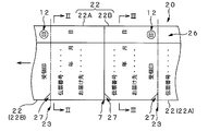
- 1 is a plan view showing a case where the above-mentioned pseudo-adhesive double-layer label without mount is used as a delivery slip 20
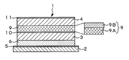
- FIG. 2 is a cross-sectional view taken along line II-II in FIG. 1
- FIG. 3 is taken along line III-III in FIG. It is sectional drawing.
- the delivery slip 20 includes a back label base 21 corresponding to the intermediate label base 3 and a front label base 22 corresponding to the front label base 4.
- the base material corresponding to the mount 2 does not use this, and has a so-called two-layer structure.
- the back side pressure sensitive adhesive layer 6 (adhesive layer) is formed on the back side of the back side label base material 21.
- the surface label base material 22 can be separated into a pasting area 22A and a receiving area 22B by a micro perforation or a cut 7 for separation, and the delivery slip 20 (pseudo-adhesive double-layer label without mount) is a pasting area 22A and a receiving area.
- the respective stacked structures are different in the region 22B. Furthermore, it can be separated at the cutting line 23 and can be used as a single leaf delivery slip 20. *
- the said front side adhesive layer 8 (adhesive layer) is formed in the back surface side of the pasting area 22A, and the back surface label base material 21 and the pasting area 22A are integrated.
- the pseudo-adhesive layer 9 is formed between the back surface label base material 21 and the front surface label base material 22, The label base material 22 is temporarily temporarily bonded.
- the pseudo-adhesive layer 9 cannot be re-adhered after being peeled off once, and the surface label base material 22 is peeled off from the back-side label base material 21 at the portion of the pseudo-adhesive layer 9. Then, the front surface label base material 22 cannot be bonded again to the back surface label base material 21.
- the pseudo adhesive layer 9 is formed by laminating an integrated pseudo adhesive paste portion 9A on the back surface label base material 21 side and an integrated pseudo adhesive peeling portion 9B on the front surface label base material 22 side. Separation is possible between the pseudo-adhesive glue portion 9A and the pseudo-adhesive peeling portion 9B.
- the adhesive force as the pseudo-adhesive layer 9 can be adjusted by forming the pseudo-adhesive paste portion 9 ⁇ / b> A with halftone dots (in the form of dots).
- the intermediate print 10 is formed in advance on the surface of the back label base 21 (the lower layer of the pseudo-adhesive glue portion 9A), and this intermediate print layer when the receiving area 22B is peeled off from the back label base 21. 10 print contents are visible. *
- thermosensitive color former layer 11 is formed on the surface of the surface label base material 22, and variable information having a predetermined content can be printed on the surface of the surface label base material 22 by a thermal printer or the like. For example, slip number, date, delivery address, etc.
- a receiving stamp column is provided so that the stamping portion 12 can be stamped.
- a release agent layer 24 is formed on the upper side of the thermosensitive color former layer 11, and between the surface of the surface label base material 22 and the back side adhesive layer 6 of the back surface label base material 21. Can be secured. *
- a narrow non-adhesive layer region 25 in which the back adhesive layer 6 is not formed is provided in a part of the back adhesive layer 6 of the back label substrate 21.
- the non-adhesive layer region 25 is positioned corresponding to the region including the stamped portion 12 on the surface label base material 22 side.
- a non-peeling layer region 26 where the release agent layer 24 is not formed is provided in a part of the release agent layer 24 of the surface label base material 22 corresponding to the non-adhesive layer region 25. Therefore, the stamped portion 12 is included in the non-peeling layer region 26.
- Both the back surface label base material 21 and the front surface label base material 22 are formed in a strip shape along the length direction of the delivery slip 20, and along this strip shape, the non-adhesive layer region 25 and the non-peeling layer region 26 are Both are formed in a strip shape with a predetermined narrow width on the front and back surfaces corresponding to the delivery slip 20 along the length direction of the back surface label base material 21 and the front surface label base material 22.
- the adhesive force between the back side adhesive layer 6 of the back surface label base material 21 and the release agent layer 24 of the front surface label base material 22 is a pseudo adhesive between the back surface label base material 21 and the front surface label base material 22. This is set to be weaker than the adhesive strength of the layer 9.
- a cutout 27 is formed in at least one corner of the front surface label base material 22 so that the front surface label base material 22 can be easily peeled off from the back surface label base material 21.
- the pseudo adhesive layer 9 may not be provided in a triangular region corresponding to the notch 27.
- a position detection mark 28 is printed in advance on the back surface of the back surface label base material 21.
- FIG. 4 is a schematic side view of a thermal printer 30 that can load and print the delivery slip 20 having such a configuration in a roll shape.
- the thermal printer 30 includes a loading unit 31 and a position detection unit of the delivery slip 20. 32, a printing unit 33, and a cutting unit 34. *
- the loading unit 31 includes a supply shaft 35 that holds the belt-shaped delivery slip 20 in a roll shape. As shown in FIG. In each delivery slip 20 located on the inner layer side and the outer layer side, the back side adhesive layer 6 of the back surface label base material 21 and the release agent layer 24 of the front surface label base material 22 come into contact with each other at a predetermined pressure. Since the releasability between the back-side pressure-sensitive adhesive layer 6 and the release agent layer 24 is ensured, it is prevented that these portions stick to each other. *
- the position detection unit 32 includes a reflective sensor 36 and can detect the position detection mark 28 (FIG. 2) on the back surface label base material 21, and can detect the relative position of the delivery slip 20 with respect to the printing unit 33. To do. *
- the printing unit 33 includes a thermal head 37 and a platen roller 38.
- the delivery slip 20 is sandwiched and transferred between the printing unit 33 and the adhesive region 22A and the receiving region 22B of the thermal labeling agent layer 11 of the surface label base material 22 are predetermined. This information can be printed.
- the outer peripheral surface of the platen roller 38 needs to be subjected to a silicone coating treatment or other peelable processing so that the adhesive of the back side adhesive layer 6 on the back side label base material 21 of the delivery slip 20 does not adhere. . *
- the cutting unit 34 has a cutting blade 39 and cuts the delivery slip 20 at the portion of the cutting line 23 (FIG. 1) to obtain a single leaf delivery slip 20. *
- the delivery slip 20 loaded in the loading unit 31 has the back label base material 21 and the front label base material 22 attached to each other as described above.
- the adhesive force between the back side pressure-sensitive adhesive layer 6 of the back surface label base material 21 and the release agent layer 24 of the front surface label base material 22 is the pseudo adhesive layer between the back surface label base material 21 and the front surface label base material 22.
- 9 is set to be weaker than the adhesive strength of 9, the back label substrate 21 and the front label substrate 22 are operated in a strip shape in the direction of the position detection unit 32, the printing unit 33, and the cutting unit 34 with an integral two-layer structure. Is possible.
- the printing unit 33 can print predetermined information on the pasting area 22A and the receiving area 22B, and the cutting unit 34 can paste the delivery slip 20 as a single leaf and paste it on a predetermined delivery item (not shown) as it is. *
- the stamped portion 12 When the delivery item is sent to the stamped portion 12 in the receiving area 22B, the stamped portion 12 is located in the non-peeling layer region 26, so that an effective stamp is possible. Furthermore, since the area on the back side of the back surface label base material 21 corresponding to the back surface of the stamped portion 12 is a non-adhesive layer area 25, the delivery slip 20 is wound in a roll shape in the loading section 31. However, it is possible to prevent the non-adhesive layer region 25 and the non-peeling layer region 26 from sticking to each other. *
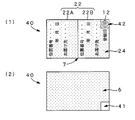
- FIG. 5 is an explanatory view showing a delivery slip 40 according to the second embodiment of the present invention, where FIG. 5 (1) is a plan view and FIG. 5 (2) is a back view.
- the delivery slip 40 does not wind the pseudo-adhesive double-layer label without a mount according to the present invention in a roll shape, and has a single leaf structure, and the surface label base material 22 on the back side has a slightly wider range than the stamped portion 12.
- a rectangular non-adhesive layer region 41 is formed, and a non-peeling layer region 42 having the same shape and area as the non-adhesive layer region 41 is formed in a rectangular shape in a slightly wider range than the stamped portion 12 on the surface-side stamped portion 12. Is forming.
- Other configurations are practically the same as the delivery slip 20 described above. *
- the delivery slip 40 having such a configuration, it is not necessary to use the mount 2, and the delivery slips 40 can be handled without being attached to each other even in the laminated state, and the attaching workability can be improved.
- mountless pseudo-adhesive double-layer label according to the present invention as an application-use seal, it is only necessary to manufacture only the receiving area 22B of the back surface label base material 21 and the front surface label base material 22 described above.
- FIG. 2 is a sectional view taken along line II-II in FIG.
- FIG. 3 is a sectional view taken along line III-III in FIG.
- FIG. 2 is a schematic side view of a thermal printer 30 in which a delivery slip 20 is loaded in a roll and can be printed and cut.
- FIG. 5 is a top view
- FIG.5 (2) is a back view.
- FIG. 7 is a sectional view taken along line VII-VII in FIG.
- FIG. 7 is a sectional view taken along line VIII-VIII in FIG.
- Non-adhesive layer region 26 Non-peeling layer region 27 Notch portion 28 Position detection mark 30 Thermal printer (FIG. 4) 31 Loading portion 32 Position detection portion 33 Printing portion 34 Cutting portion 35 Supply shaft 36 Reflective sensor 37 Thermal head 38 Platen roller 39 Cutting blade 40 Delivery slip (second embodiment of pseudo-adhesive double-layer label without mount, FIG. 5) 41 Non-adhesive layer region 42 Non-peeling layer region
Abstract
[PROBLEMS] To provide a false adhesion two layer label with no mount which can ensure efficient labeling work by not using the mount that would generate dust due to its structure thereby saving the labor for stripping the mount. [MEANS FOR SOLVING PROBLEMS] In order to eliminate the need for using a mount when the label is utilized as a delivery slip or a seal for application, and to secure strippability between an adhesive layer (6) located on the backside and a layer located on the surface/back side surface so that a surface label base material (22) positioned on the surface side or its thermal coloring agent layer (11) does not stick, the false adhesion two layer label with no mount comprises a backside label base material (21) having the adhesive layer (6) on the backside, and a surface label base material (22) laminated on the surface side of the backside label base material (21) through a false adhesive layer (9), characterized in that a release agent layer (24) ensuring strippability from the adhesive layer (6) of the backside label base material (21) is formed on the surface of the surface label base material (22).
Description
本発明は台紙なし擬似接着二層ラベルにかかるもので、とくに配送伝票その他の伝票や応募用シールなどに用いられる台紙なし擬似接着二層ラベルに関するものである。
The present invention relates to a non-mounting pseudo-adhesive double-layer label, and more particularly to a non-mounting pseudo-adhesive double-layer label used for delivery slips and other slips, application seals, and the like.
従来の配送伝票その他の伝票や応募用シールなどに用いられる擬似接着ラベルとしては、三層構造のものがある。 図6ないし図8にもとづき概説する。 図6は、配送伝票として応用した従来の擬似接着三層ラベル1の平面図、図7は、図6のVII-VII線断面図、図8は、図6のVIII-VIII線断面図である。 擬似接着三層ラベル1(配送伝票)は、台紙2(剥離紙)と、中間ラベル基材3と、表面ラベル基材4と、を有し、いわゆる三層構造を呈している。
Conventional pseudo-adhesive labels used for delivery slips, other slips, application stickers, and the like have a three-layer structure. Outlined based on FIG. 6 to FIG. 6 is a plan view of a conventional pseudo-adhesive three-layer label 1 applied as a delivery slip, FIG. 7 is a sectional view taken along line VII-VII in FIG. 6, and FIG. 8 is a sectional view taken along line VIII-VIII in FIG. . The pseudo-adhesive three-layer label 1 (delivery slip) has a mount 2 (release paper), an intermediate label base material 3, and a surface label base material 4, and has a so-called three-layer structure. *
台紙2は、その表面に剥離剤層5を形成してあり、その裏面に裏側粘着剤層6(粘着剤層)を形成した上記中間ラベル基材3を仮着可能である。 表面ラベル基材4は、マイクロミシン目や切離し用カット7などによって貼付け領域4Aおよび受領領域4Bに分離可能としてあり、擬似接着三層ラベル1としては、貼付け領域4Aおよび受領領域4Bにおいてそれぞれの積層構造が異なっている。 すなわち、貼付け領域4Aにおいては、図7に示すように、貼付け領域4Aの裏面側に表側粘着剤層8(粘着剤層)を形成し、中間ラベル基材3と貼付け領域4Aとを一体化している。 受領領域4Bにおいては、図8に示すように、中間ラベル基材3と表面ラベル基材4との間には、擬似接着剤層9を形成してあって、中間ラベル基材3と表面ラベル基材4とを一時的に仮接着している。
The backing paper 2 has a release agent layer 5 formed on the surface thereof, and the intermediate label substrate 3 on which the back side adhesive layer 6 (adhesive layer) is formed can be temporarily attached. The surface label base material 4 can be separated into the pasting area 4A and the receiving area 4B by a micro perforation, a cut 7 for separating, and the pseudo-adhesive three-layer label 1 is laminated in the pasting area 4A and the receiving area 4B. The structure is different. That is, in the pasting area 4A, as shown in FIG. 7, the front side adhesive layer 8 (adhesive layer) is formed on the back side of the pasting area 4A, and the intermediate label substrate 3 and the pasting area 4A are integrated. Yes. In the receiving area 4B, as shown in FIG. 8, a pseudo adhesive layer 9 is formed between the intermediate label substrate 3 and the surface label substrate 4, and the intermediate label substrate 3 and the surface label are formed. The substrate 4 is temporarily temporarily bonded. *
この擬似接着剤層9は、一度剥離したのちは、再度の接着ができなくなるもので、擬似接着剤層9の部分において中間ラベル基材3から表面ラベル基材4を剥離すると、この表面ラベル基材4を中間ラベル基材3には再度接着することができなくなる。 擬似接着剤層9としては、たとえば、圧着糊を用いて中間ラベル基材3および表面ラベル基材4を高圧で貼り合わせる方式、ポリエチレン樹脂などを用いて貼り合わせる方式など各種あるが、図示の例では、中間ラベル基材3側に一体的な擬似接着糊部9Aおよび表面ラベル基材4側に一体的な擬似接着剥離部9Bを積層して、この擬似接着糊部9Aと擬似接着剥離部9Bとの間で剥離(分離)が可能となるようにしている。
The pseudo-adhesive layer 9 cannot be re-adhered after being peeled once. When the surface label base 4 is peeled from the intermediate label base 3 at the portion of the pseudo-adhesive layer 9, the surface label base The material 4 cannot be bonded again to the intermediate label substrate 3. Examples of the pseudo adhesive layer 9 include various methods such as a method in which the intermediate label substrate 3 and the surface label substrate 4 are bonded at a high pressure using a pressure-sensitive adhesive, and a method in which the intermediate label substrate 3 is bonded using a polyethylene resin. Then, an integrated pseudo-adhesive glue part 9A on the intermediate label base material 3 side and an integrated pseudo-adhesive peel part 9B on the surface label base material 4 side are laminated, and the pseudo-adhesive glue part 9A and the pseudo-adhesive peel part 9B are laminated. Can be separated (separated). *
なお、中間ラベル基材3の表面(擬似接着糊部9Aの下層)には、宣伝用あるいは挨拶用などの中間印刷層10をあらかじめ形成してあり、受領領域4Bを中間ラベル基材3からはがしたときにこの中間印刷層10の印刷内容を視認可能としてある。
An intermediate printed layer 10 for advertising or greeting is formed in advance on the surface of the intermediate label base 3 (the lower layer of the pseudo-adhesive glue portion 9A), and the receiving area 4B is separated from the intermediate label base 3 The printed content of the intermediate print layer 10 can be visually recognized when the error occurs. *
表面ラベル基材4の表面には、感熱発色剤層11を形成してあり、サーマルプリンターなどにより表面ラベル基材4の表面に所定内容の可変情報を印字可能としてある。たとえば、伝票番号、日付け、お届け先等々である。 とくに受領領域4Bには、受領印欄を設けて押印部12に押印可能としている。
A heat-sensitive color former layer 11 is formed on the surface of the surface label substrate 4 so that variable information having a predetermined content can be printed on the surface of the surface label substrate 4 by a thermal printer or the like. For example, slip number, date, delivery address, etc. In particular, in the receiving area 4B, a receiving stamp field is provided so that the stamping portion 12 can be stamped. *
なお、台紙2には、表面ラベル基材4のピッチに合わせて所定間隔で分離用ミシン目13を設けている。 また、擬似接着三層ラベル1の位置検出には、分離用ミシン目13が形成されている台紙2と、中間ラベル基材3および表面ラベル基材4との間の段差部分を利用することもできるし、必要であれば、その裏面に位置検出用マーク14(図7中、仮想線)をあらかじめ印刷しておくこともできる。
The mount 2 is provided with separation perforations 13 at predetermined intervals according to the pitch of the surface label base material 4. Further, for detecting the position of the pseudo-adhesive three-layer label 1, a step portion between the mount 2 on which the separation perforation 13 is formed and the intermediate label base material 3 and the surface label base material 4 may be used. If necessary, the position detection mark 14 (virtual line in FIG. 7) can be printed in advance on the back surface. *
こうした構成の擬似接着三層ラベル1(配送伝票)において、表面ラベル基材4(貼付け領域4A、受領領域4B)に所定の情報を印字した上で中間ラベル基材3の裏面から台紙2を剥離し、中間ラベル基材3およびその上層側すなわち表面ラベル基材4までを配送品(図示せず)に貼り付けて配送する。 配送先で押印部12に受領印を押印してもらうとともに、切離し用カット7の部分で貼付け領域4Aおよび受領領域4Bを切り離し可能として、擬似接着剤層9(擬似接着糊部9A、擬似接着剥離部9B)の部分で表面ラベル基材4の受領領域4Bを中間ラベル基材3および貼付け領域4Aからはがし、配送確認用として持ち帰る。
In the pseudo-adhesive three-layer label 1 (delivery slip) having such a configuration, predetermined information is printed on the surface label base material 4 (the pasting area 4A and the receiving area 4B), and then the mount 2 is peeled from the back surface of the intermediate label base material 3 Then, the intermediate label base material 3 and the upper layer side thereof, that is, the surface label base material 4 are attached to a delivery product (not shown) and delivered. At the delivery destination, the stamping part 12 is imprinted with a receipt mark, and the adhesive region 4A and the receiving region 4B can be separated at the part of the cut 7 for separation. The receiving area 4B of the surface label base material 4 is peeled off from the intermediate label base material 3 and the pasting area 4A at the portion 9B) and brought back for delivery confirmation. *
しかしながら、配送品に中間ラベル基材3および表面ラベル基材4を貼り付けたのちは、台紙2部分はゴミとして廃棄されるだけであるという問題がある。 しかも、上記可変情報を表面ラベル基材4に印字したのち、分離用ミシン目13の部分で単葉とした擬似接着三層ラベル1から台紙2をはがす作業が手間であり、作業性向上の点からも問題となっている。
However, after the intermediate label base material 3 and the surface label base material 4 are attached to the delivery product, there is a problem that the mount 2 portion is only discarded as garbage. Moreover, after the variable information is printed on the surface label base material 4, the work of peeling the mount 2 from the pseudo-adhesive three-layer label 1 made into a single leaf at the separation perforation 13 is troublesome, and from the viewpoint of improving workability Is also a problem. *
このような問題は、擬似接着三層ラベル1を配送伝票としてのみに限らず、表面ラベル基材4の受領領域4B部分およびその下層部分のみの構成を有する応募用シールなどとして用いる場合にも同様に発生する問題である。
Such a problem is not limited to the case where the pseudo-adhesive three-layer label 1 is used not only as a delivery slip, but also when used as an application seal having a configuration of only the receiving region 4B portion and the lower layer portion of the surface label base material 4. It is a problem that occurs. *
本発明は以上のような諸問題にかんがみなされたもので、その構成から台紙を省いてゴミを出さないようにした台紙なし擬似接着二層ラベルを提供することを課題とする。
The present invention has been considered in view of the above problems, and an object of the present invention is to provide a pseudo-adhesive double-layer label without a mount so as not to generate dust by omitting the mount. *
また本発明は、台紙をゴミとして出すことなく、環境にも優しい台紙なし擬似接着二層ラベルを提供することを課題とする。
Another object of the present invention is to provide an environmentally friendly non-mounting pseudo-adhesive double-layer label without taking out the mount as waste. *
また本発明は、台紙を剥離する手間を省き、ラベルとしての貼付け作業の効率化が可能な台紙なし擬似接着二層ラベルを提供することを課題とする。
Another object of the present invention is to provide a pseudo-adhesive double-layer label without a mount, which can save the labor of peeling the mount and can improve the efficiency of the attaching operation as a label.
すなわち本発明は、配送伝票あるいは応募用シールなどとして利用する場合に、台紙を用いる必要がないようにすること、さらに、この種ラベルは一般的にはロール状に巻き取るか、あるいはファンホールド状に折りたたむようにするので、裏面側に位置する粘着剤層と表面側に位置する表面ラベル基材ないしその感熱発色剤層が貼り付かないように表裏の面に位置することになる層の間で剥離性を確保することに着目したもので、その裏面に粘着剤層を有する裏面ラベル基材と、この裏面ラベル基材の表面側に擬似接着剤層を介して積層する表面ラベル基材と、を有するとともに、上記表面ラベル基材の表面に上記裏面ラベル基材の上記粘着剤層との間の剥離性を確保可能な剥離剤層を形成したことを特徴とする台紙なし擬似接着二層ラベルである。
That is, the present invention makes it unnecessary to use a mount when used as a delivery slip or an application sticker, and moreover, such a label is generally rolled up in a roll shape or in a fan hold shape. Between the layers that will be located on the front and back surfaces so that the adhesive layer located on the back side and the surface label base material located on the front side or its thermal color former layer will not stick. Focusing on ensuring releasability, a back surface label base material having an adhesive layer on its back surface, a surface label base material laminated on the front surface side of this back surface label base material via a pseudo adhesive layer, And a backing layer-free pseudo-adhesive two-layer label characterized in that a release agent layer capable of ensuring release properties from the adhesive layer of the back surface label substrate is formed on the surface of the surface label substrate. It is. *
上記表面ラベル基材の表面に、上記剥離剤層の下層側に感熱発色剤層を形成してあることができる。
A thermosensitive color former layer may be formed on the surface of the surface label base material on the lower layer side of the release agent layer. *
上記裏面ラベル基材の上記粘着剤層の一部において上記粘着剤層を形成していない非粘着層領域を設けるとともに、上記表面ラベル基材の上記剥離剤層の一部においてこの非粘着層領域に対応する領域に位置させるとともに上記剥離剤層を形成していない非剥離層領域を設けることができる。
A non-adhesive layer region in which the pressure-sensitive adhesive layer is not formed is provided in a part of the pressure-sensitive adhesive layer of the back surface label base material, and this non-adhesive layer region is provided in a part of the release agent layer of the surface label base material. It is possible to provide a non-release layer region in which the release agent layer is not formed while being positioned in a region corresponding to the above. *
上記裏面ラベル基材および上記表面ラベル基材はともに、これを帯状に形成し、さらに、上記非粘着層領域および上記非剥離層領域はともに、上記裏面ラベル基材および上記表面ラベル基材の長さ方向に沿ってこれを帯状に形成することができる。
The back label substrate and the surface label substrate are both formed into a band shape, and the non-adhesive layer region and the non-peeling layer region are both the lengths of the back label substrate and the surface label substrate. This can be formed in a strip shape along the vertical direction. *
上記裏面ラベル基材の上記粘着剤層と上記表面ラベル基材の上記剥離剤層との間の粘着力は、上記裏面ラベル基材と上記表面ラベル基材との間の上記擬似接着剤層の接着強さより弱いように設定することができる。
The adhesive force between the pressure-sensitive adhesive layer of the back surface label base material and the release agent layer of the surface label base material is that of the pseudo adhesive layer between the back surface label base material and the surface label base material. It can be set to be weaker than the adhesive strength. *
上記表面ラベル基材の隅部に切欠き部を形成してあることができる。
A notch can be formed in the corner of the surface label substrate. *
上記裏面ラベル基材の表面には、必要に応じて所望の内容の情報をあらかじめ印刷しておくことができる。
Information on the desired content can be printed in advance on the surface of the back label substrate as necessary.
本発明による台紙なし擬似接着二層ラベルにおいては、その裏面に粘着剤層を有する裏面ラベル基材と、この裏面ラベル基材の表面に設ける擬似接着剤層と、この擬似接着剤層の表面に設ける表面ラベル基材と、を有するとともに、表面ラベル基材の表面に粘着剤層の剥離性を確保可能な剥離剤層を形成したので、ロール状に巻き取るか、あるいはファンホールド状に折りたたまれた状態であっても、裏面側と表面側とが貼り付くことなく取り扱うことができる。 したがって、従来のように剥離したのちの台紙をゴミとして発生させることがないとともに、台紙の剥離作業が不要で、作業の効率化が可能である。
In the pseudo-adhesive double-layer label without a backing according to the present invention, a back label substrate having an adhesive layer on the back surface, a pseudo adhesive layer provided on the surface of the back label substrate, and a surface of the pseudo adhesive layer And a surface label base material to be provided, and a release agent layer capable of ensuring the peelability of the pressure-sensitive adhesive layer is formed on the surface of the surface label base material, so that it is wound up in a roll shape or folded into a fan hold shape. Even in such a state, the back side and the front side can be handled without sticking. Therefore, the mount after being peeled off as in the prior art is not generated as garbage, and the work for removing the mount is unnecessary, and the work efficiency can be improved.
本発明は、台紙を省いて二層構造とするとともに、裏面側に位置する粘着剤層と表面側に位置する表面ラベル基材ないしその感熱発色剤層が貼り付かないように剥離性を確保するようにしたので、環境上および作業性上すぐれた台紙なし擬似接着二層ラベルを実現した。
The present invention has a two-layer structure by omitting the mount, and ensures releasability so that the pressure-sensitive adhesive layer located on the back side and the surface label base material located on the front side or the heat-sensitive color former layer do not stick. As a result, a pseudo-adhesive double-layer label without mounting was realized that was excellent in terms of environment and workability.
つぎに本発明の第1の実施例による台紙なし擬似接着二層ラベルを図1ないし図4にもとづき説明する。ただし、図6ないし図8と同様の部分には同一符号を付し、その詳述はこれを省略する。 図1は、上記台紙なし擬似接着二層ラベルを配送伝票20として用いた場合を示す平面図、図2は、図1のII-II線断面図、図3は、図1のIII-III線断面図である。 配送伝票20は、前記中間ラベル基材3に相当する裏面ラベル基材21と、前記表面ラベル基材4に相当する表面ラベル基材22と、を有する。前記台紙2に相当する基材はこれを用いておらず、いわゆる二層構造を呈している。 裏面ラベル基材21には、その裏面に前記裏側粘着剤層6(粘着剤層)を形成している。 表面ラベル基材22は、マイクロミシン目や切離し用カット7などにより貼付け領域22Aおよび受領領域22Bに分離可能としてあり、配送伝票20(台紙なし擬似接着二層ラベル)としては、貼付け領域22Aおよび受領領域22Bにおいてそれぞれの積層構造が異なっている。さらに、切断線23において切り離し可能であって、単葉の配送伝票20として利用可能としている。
Next, a pseudo-adhesive double-layer label without a mount according to the first embodiment of the present invention will be described with reference to FIGS. However, the same parts as those in FIGS. 6 to 8 are denoted by the same reference numerals, and detailed description thereof will be omitted. 1 is a plan view showing a case where the above-mentioned pseudo-adhesive double-layer label without mount is used as a delivery slip 20, FIG. 2 is a cross-sectional view taken along line II-II in FIG. 1, and FIG. 3 is taken along line III-III in FIG. It is sectional drawing. The delivery slip 20 includes a back label base 21 corresponding to the intermediate label base 3 and a front label base 22 corresponding to the front label base 4. The base material corresponding to the mount 2 does not use this, and has a so-called two-layer structure. The back side pressure sensitive adhesive layer 6 (adhesive layer) is formed on the back side of the back side label base material 21. The surface label base material 22 can be separated into a pasting area 22A and a receiving area 22B by a micro perforation or a cut 7 for separation, and the delivery slip 20 (pseudo-adhesive double-layer label without mount) is a pasting area 22A and a receiving area. The respective stacked structures are different in the region 22B. Furthermore, it can be separated at the cutting line 23 and can be used as a single leaf delivery slip 20. *
貼付け領域22Aにおいては、図2に示すように、貼付け領域22Aの裏面側に前記表側粘着剤層8(粘着剤層)を形成し、裏面ラベル基材21と貼付け領域22Aとを一体化している。 受領領域22Bにおいては、図3に示すように、裏面ラベル基材21と表面ラベル基材22との間には、前記擬似接着剤層9を形成してあって、裏面ラベル基材21と表面ラベル基材22とを一時的に仮接着している。
In the pasting area 22A, as shown in FIG. 2, the said front side adhesive layer 8 (adhesive layer) is formed in the back surface side of the pasting area 22A, and the back surface label base material 21 and the pasting area 22A are integrated. . In the receiving area 22B, as shown in FIG. 3, the pseudo-adhesive layer 9 is formed between the back surface label base material 21 and the front surface label base material 22, The label base material 22 is temporarily temporarily bonded. *
この擬似接着剤層9は、既述のように、一度剥離したのちは、再度の接着
ができなくなるもので、擬似接着剤層9の部分において裏面ラベル基材21から表面ラベル基材22を剥離すると、この表面ラベル基材22を裏面ラベル基材21には再度接着することができなくなる。 擬似接着剤層9としては、図示の例では、裏面ラベル基材21側に一体的な擬似接着糊部9Aおよび表面ラベル基材22側に一体的な擬似接着剥離部9Bを積層して、この擬似接着糊部9Aと擬似接着剥離部9Bとの間で分離が可能となるようにしている。なお、擬似接着糊部9Aを網点で(点状に)形成することにより、擬似接着剤層9としての接着力を調整可能である。 As described above, thepseudo-adhesive layer 9 cannot be re-adhered after being peeled off once, and the surface label base material 22 is peeled off from the back-side label base material 21 at the portion of the pseudo-adhesive layer 9. Then, the front surface label base material 22 cannot be bonded again to the back surface label base material 21. In the illustrated example, the pseudo adhesive layer 9 is formed by laminating an integrated pseudo adhesive paste portion 9A on the back surface label base material 21 side and an integrated pseudo adhesive peeling portion 9B on the front surface label base material 22 side. Separation is possible between the pseudo-adhesive glue portion 9A and the pseudo-adhesive peeling portion 9B. In addition, the adhesive force as the pseudo-adhesive layer 9 can be adjusted by forming the pseudo-adhesive paste portion 9 </ b> A with halftone dots (in the form of dots).
ができなくなるもので、擬似接着剤層9の部分において裏面ラベル基材21から表面ラベル基材22を剥離すると、この表面ラベル基材22を裏面ラベル基材21には再度接着することができなくなる。 擬似接着剤層9としては、図示の例では、裏面ラベル基材21側に一体的な擬似接着糊部9Aおよび表面ラベル基材22側に一体的な擬似接着剥離部9Bを積層して、この擬似接着糊部9Aと擬似接着剥離部9Bとの間で分離が可能となるようにしている。なお、擬似接着糊部9Aを網点で(点状に)形成することにより、擬似接着剤層9としての接着力を調整可能である。 As described above, the
なお、裏面ラベル基材21の表面(擬似接着糊部9Aの下層)には前記中間印刷10をあらかじめ形成してあり、受領領域22Bを裏面ラベル基材21からはがしたときにこの中間印刷層10の印刷内容を視認可能としてある。
The intermediate print 10 is formed in advance on the surface of the back label base 21 (the lower layer of the pseudo-adhesive glue portion 9A), and this intermediate print layer when the receiving area 22B is peeled off from the back label base 21. 10 print contents are visible. *
表面ラベル基材22の表面には、前記感熱発色剤層11を形成してあり、サーマルプリンターなどにより表面ラベル基材22の表面に所定内容の可変情報を印字可能としてある。たとえば、伝票番号、日付け、お届け先等々である。 とくに受領領域22Bには、受領印欄を設けて押印部12に押印可能としている。
The thermosensitive color former layer 11 is formed on the surface of the surface label base material 22, and variable information having a predetermined content can be printed on the surface of the surface label base material 22 by a thermal printer or the like. For example, slip number, date, delivery address, etc. In particular, in the receiving area 22B, a receiving stamp column is provided so that the stamping portion 12 can be stamped. *
表面ラベル基材22の表面には、感熱発色剤層11の上層側に剥離剤層24を形成して、表面ラベル基材22の表面と裏面ラベル基材21の裏側粘着剤層6との間の剥離性を確保可能としている。
On the surface of the surface label base material 22, a release agent layer 24 is formed on the upper side of the thermosensitive color former layer 11, and between the surface of the surface label base material 22 and the back side adhesive layer 6 of the back surface label base material 21. Can be secured. *
ただし、とくに図2および図3に示すように、裏面ラベル基材21の裏側粘着剤層6の一部において裏側粘着剤層6を形成していない細幅状の非粘着層領域25を設ける。 この非粘着層領域25は、表面ラベル基材22側の押印部12を含む領域にこれを対応位置させている。 さらに、非粘着層領域25に対応して表面ラベル基材22の剥離剤層24の一部において剥離剤層24を形成していない非剥離層領域26を設けている。したがって、押印部12は、非剥離層領域26に含まれることになる。 裏面ラベル基材21および表面ラベル基材22はともに、配送伝票20の長さ方向に沿って帯状に形成されており、この帯状形状に沿って、非粘着層領域25および非剥離層領域26はともに、裏面ラベル基材21および表面ラベル基材22の長さ方向に沿って配送伝票20の対応する表裏面においてこれを所定の細幅で互いに帯状に形成していることになる。
However, as shown in FIG. 2 and FIG. 3 in particular, a narrow non-adhesive layer region 25 in which the back adhesive layer 6 is not formed is provided in a part of the back adhesive layer 6 of the back label substrate 21. The non-adhesive layer region 25 is positioned corresponding to the region including the stamped portion 12 on the surface label base material 22 side. Further, a non-peeling layer region 26 where the release agent layer 24 is not formed is provided in a part of the release agent layer 24 of the surface label base material 22 corresponding to the non-adhesive layer region 25. Therefore, the stamped portion 12 is included in the non-peeling layer region 26. Both the back surface label base material 21 and the front surface label base material 22 are formed in a strip shape along the length direction of the delivery slip 20, and along this strip shape, the non-adhesive layer region 25 and the non-peeling layer region 26 are Both are formed in a strip shape with a predetermined narrow width on the front and back surfaces corresponding to the delivery slip 20 along the length direction of the back surface label base material 21 and the front surface label base material 22. *
なお、裏面ラベル基材21の裏側粘着剤層6と表面ラベル基材22の剥離剤層24との間の粘着力は、裏面ラベル基材21と表面ラベル基材22との間の擬似接着剤層9の接着強さより弱くこれを設定しておく。
In addition, the adhesive force between the back side adhesive layer 6 of the back surface label base material 21 and the release agent layer 24 of the front surface label base material 22 is a pseudo adhesive between the back surface label base material 21 and the front surface label base material 22. This is set to be weaker than the adhesive strength of the layer 9. *
表面ラベル基材22の少なくともひとつの隅部には、切欠き部27を形成して、裏面ラベル基材21から表面ラベル基材22をはがしやすくしている。 あるいは、切欠き部27を形成する代わりに、切欠き部27に相当する三角形状の領域について擬似接着剤層9を設けないようにすることもできる。
A cutout 27 is formed in at least one corner of the front surface label base material 22 so that the front surface label base material 22 can be easily peeled off from the back surface label base material 21. Alternatively, instead of forming the notch 27, the pseudo adhesive layer 9 may not be provided in a triangular region corresponding to the notch 27. *
なお、図2に示すように、裏面ラベル基材21の裏面には、位置検出用マーク28をあらかじめ印刷してある。
As shown in FIG. 2, a position detection mark 28 is printed in advance on the back surface of the back surface label base material 21. *
図4は、こうした構成の配送伝票20をロール状に装填して印字かつ切断可能なサーマルプリンター30の概略側面図であって、サーマルプリンター30は、配送伝票20の装填部31と、位置検出部32と、印字部33と、切断部34と、を有する。
FIG. 4 is a schematic side view of a thermal printer 30 that can load and print the delivery slip 20 having such a configuration in a roll shape. The thermal printer 30 includes a loading unit 31 and a position detection unit of the delivery slip 20. 32, a printing unit 33, and a cutting unit 34. *
装填部31は、帯状の配送伝票20をロール状に巻いた状態で保持する供給軸35を有し、図4中、ロール状の配送伝票20の一部を拡大して示すように、ロールの内層側および外層側に位置するそれぞれ配送伝票20において、裏面ラベル基材21の裏側粘着剤層6と表面ラベル基材22の剥離剤層24とが互いに所定圧力で接触し合うことになるが、裏側粘着剤層6と剥離剤層24との間での剥離性は確保されているので、この部分で互いに貼り付いてしまうことを防止している。
The loading unit 31 includes a supply shaft 35 that holds the belt-shaped delivery slip 20 in a roll shape. As shown in FIG. In each delivery slip 20 located on the inner layer side and the outer layer side, the back side adhesive layer 6 of the back surface label base material 21 and the release agent layer 24 of the front surface label base material 22 come into contact with each other at a predetermined pressure. Since the releasability between the back-side pressure-sensitive adhesive layer 6 and the release agent layer 24 is ensured, it is prevented that these portions stick to each other. *
位置検出部32は、反射型のセンサー36を有し、裏面ラベル基材21の位置検出用マーク28(図2)を検出可能として、印字部33に対する配送伝票20の相対的位置を検出可能とする。
The position detection unit 32 includes a reflective sensor 36 and can detect the position detection mark 28 (FIG. 2) on the back surface label base material 21, and can detect the relative position of the delivery slip 20 with respect to the printing unit 33. To do. *
印字部33は、サーマルヘッド37およびプラテンローラー38を有し、この間に配送伝票20を挟持移送して、表面ラベル基材22の感熱発色剤層11においてそれぞれの貼付け領域22Aおよび受領領域22Bに所定の情報を印字可能とする。 ただし、プラテンローラー38の外周面には、シリコーンコーティング処理その他の剥離性加工を施して、配送伝票20の裏面ラベル基材21における裏側粘着剤層6の粘着剤が付着しないようにする必要がある。
The printing unit 33 includes a thermal head 37 and a platen roller 38. The delivery slip 20 is sandwiched and transferred between the printing unit 33 and the adhesive region 22A and the receiving region 22B of the thermal labeling agent layer 11 of the surface label base material 22 are predetermined. This information can be printed. However, the outer peripheral surface of the platen roller 38 needs to be subjected to a silicone coating treatment or other peelable processing so that the adhesive of the back side adhesive layer 6 on the back side label base material 21 of the delivery slip 20 does not adhere. . *
切断部34は、切断刃39を有し、切断線23(図1)の部分において配送伝票20を切断し、単葉の配送伝票20とする。
The cutting unit 34 has a cutting blade 39 and cuts the delivery slip 20 at the portion of the cutting line 23 (FIG. 1) to obtain a single leaf delivery slip 20. *
こうした構成の配送伝票20およびサーマルプリンター30において、装填部31に装填された配送伝票20は、既述のように裏面ラベル基材21および表面ラベル基材22が互いに貼り付いてしまわないため、さらに、裏面ラベル基材21の裏側粘着剤層6と表面ラベル基材22の剥離剤層24との間の粘着力は、裏面ラベル基材21と表面ラベル基材22との間の擬似接着剤層9の接着強さより弱く設定されているので、裏面ラベル基材21および表面ラベル基材22は一体の二層構造のまま、位置検出部32、印字部33および切断部34の方向に帯状に操出可能である。 印字部33で貼付け領域22Aおよび受領領域22Bに所定の情報を印字し、切断部34において配送伝票20を単葉として、そのまま所定の配送品(図示せず)に貼り付けることができる。
In the delivery slip 20 and the thermal printer 30 configured as described above, the delivery slip 20 loaded in the loading unit 31 has the back label base material 21 and the front label base material 22 attached to each other as described above. The adhesive force between the back side pressure-sensitive adhesive layer 6 of the back surface label base material 21 and the release agent layer 24 of the front surface label base material 22 is the pseudo adhesive layer between the back surface label base material 21 and the front surface label base material 22. 9 is set to be weaker than the adhesive strength of 9, the back label substrate 21 and the front label substrate 22 are operated in a strip shape in the direction of the position detection unit 32, the printing unit 33, and the cutting unit 34 with an integral two-layer structure. Is possible. The printing unit 33 can print predetermined information on the pasting area 22A and the receiving area 22B, and the cutting unit 34 can paste the delivery slip 20 as a single leaf and paste it on a predetermined delivery item (not shown) as it is. *
配送品の届け先において、受領領域22Bの押印部12に押印をしてもらう際に、押印部12は非剥離層領域26に位置しているので、有効な押印が可能である。 さらに、この押印部12部分に裏面で相当する裏面ラベル基材21の裏側の領域は、非粘着層領域25とされているので、装填部31において配送伝票20をロール状に巻いた状態であっても、これら非粘着層領域25および非剥離層領域26の領域が互いに貼り付いてしまうことを防止可能である。
When the delivery item is sent to the stamped portion 12 in the receiving area 22B, the stamped portion 12 is located in the non-peeling layer region 26, so that an effective stamp is possible. Furthermore, since the area on the back side of the back surface label base material 21 corresponding to the back surface of the stamped portion 12 is a non-adhesive layer area 25, the delivery slip 20 is wound in a roll shape in the loading section 31. However, it is possible to prevent the non-adhesive layer region 25 and the non-peeling layer region 26 from sticking to each other. *
図5は、本発明の第2の実施例による配送伝票40を示す説明図であって、図5(1)は、平面図、図5(2)は、裏面図である。 配送伝票40は、本発明による台紙なし擬似接着二層ラベルをロール状に巻かず、単葉のままの構成を有し、裏面側の表面ラベル基材22には、押印部12よりやや広い範囲に矩形状の非粘着層領域41を形成し、表面側の押印部12には、この押印部12よりやや広い範囲に矩形状に非粘着層領域41と同様の形状および面積の非剥離層領域42を形成している。 他の構成は、既述した配送伝票20と事実上同じである。
FIG. 5 is an explanatory view showing a delivery slip 40 according to the second embodiment of the present invention, where FIG. 5 (1) is a plan view and FIG. 5 (2) is a back view. The delivery slip 40 does not wind the pseudo-adhesive double-layer label without a mount according to the present invention in a roll shape, and has a single leaf structure, and the surface label base material 22 on the back side has a slightly wider range than the stamped portion 12. A rectangular non-adhesive layer region 41 is formed, and a non-peeling layer region 42 having the same shape and area as the non-adhesive layer region 41 is formed in a rectangular shape in a slightly wider range than the stamped portion 12 on the surface-side stamped portion 12. Is forming. Other configurations are practically the same as the delivery slip 20 described above. *
こうした構成の配送伝票40によっても、前記台紙2を用いる必要がなく、配送伝票40を積層状態においても互いに貼り付くことなく取り扱うことが可能であるとともに、貼付け作業性を向上させることができる。
Also with the delivery slip 40 having such a configuration, it is not necessary to use the mount 2, and the delivery slips 40 can be handled without being attached to each other even in the laminated state, and the attaching workability can be improved. *
なお、本発明による台紙なし擬似接着二層ラベルを応募兼用シールとして応用する場合には、上述した裏面ラベル基材21および表面ラベル基材22の受領領域22Bの部分のみを製造すればよい。
In addition, when applying the mountless pseudo-adhesive double-layer label according to the present invention as an application-use seal, it is only necessary to manufacture only the receiving area 22B of the back surface label base material 21 and the front surface label base material 22 described above.
1 擬似接着三層ラベル(従来の配送伝票、図6) 2 台紙 3 中間ラベル基材 4 表面ラベル基材 4A 表面ラベル基材4の貼付け領域 4B 表面ラベル基材4の受領領域 5 剥離剤層 6 裏側粘着剤層(粘着剤層) 7 マイクロミシン目や切離し用カット 8 表側粘着剤層(粘着剤層) 9 擬似接着剤層 9A 擬似接着剤層9の擬似接着糊部 9B 擬似接着剤層9の擬似接着剥離部10 中間印刷層11 感熱発色剤層12 押印部13 分離用ミシン目14 位置検出用マーク20 配送伝票(台紙なし擬似接着二層ラベルの第1の実施例、図1)21 裏面ラベル基材22 表面ラベル基材22A 表面ラベル基材22の貼付け領域22B 表面ラベル基材22の受領領域23 切断線24 剥離剤層25 非粘着層領域26 非剥離層領域27 切欠き部28 位置検出用マーク30 サーマルプリンター(図4)31 装填部32 位置検出部33 印字部34 切断部35 供給軸36 反射型のセンサー37 サーマルヘッド38 プラテンローラー39 切断刃40 配送伝票(台紙なし擬似接着二層ラベルの第2の実施例、図5)41 非粘着層領域42 非剥離層領域
1 Pseudo-adhesive three-layer label (conventional delivery slip, FIG. 6) 2 Mount 3 Intermediate label base 4 Surface label base 4A Surface label base 4 pasting area 4B Surface label base 4 receiving area 5 Release agent layer 6 Back side pressure-sensitive adhesive layer (pressure-sensitive adhesive layer) 7 Micro perforations and cuts for cutting 8 Front side pressure-sensitive adhesive layer (pressure-sensitive adhesive layer) 9 Pseudo-adhesive layer 9A Pseudo-adhesive glue part 9B Pseudo-adhesive layer 9 Pseudo-adhesive peeling part 10 Intermediate printing layer 11 Thermosensitive color former layer 12 Stamping part 13 Separation perforation 14 Position detection mark 20 Delivery slip (first embodiment of pseudo-adhesive double-layer label without mount, FIG. 1) 21 Back label Base material 22 Surface label base material 22A Surface label base material 22 pasting area 22B Surface label base material 22 receiving area 23 Cutting line 24 Release agent layer 25 Non-adhesive layer region 26 Non-peeling layer region 27 Notch portion 28 Position detection mark 30 Thermal printer (FIG. 4) 31 Loading portion 32 Position detection portion 33 Printing portion 34 Cutting portion 35 Supply shaft 36 Reflective sensor 37 Thermal head 38 Platen roller 39 Cutting blade 40 Delivery slip (second embodiment of pseudo-adhesive double-layer label without mount, FIG. 5) 41 Non-adhesive layer region 42 Non-peeling layer region
Claims (6)
- その裏面に粘着剤層を有する裏面ラベル基材と、 この裏面ラベル基材の表面側に擬似接着剤層を介して積層する表面ラベル基材と、 を有するとともに、 前記表面ラベル基材の表面に前記裏面ラベル基材の前記粘着剤層との間の剥離性を確保可能な剥離剤層を形成したことを特徴とする台紙なし擬似接着二層ラベル。 A back surface label base material having a pressure-sensitive adhesive layer on the back surface, a front surface label base material laminated on the front surface side of the back surface label base material via a pseudo-adhesive layer, and on the surface of the front surface label base material A pseudo-adhesive double-layer label without mount, wherein a release agent layer capable of ensuring release properties between the back surface label substrate and the pressure-sensitive adhesive layer is formed.
- 前記表面ラベル基材の表面に、前記剥離剤層の下層側に感熱発色剤層を形成してあることを特徴とする請求項1記載の台紙なし擬似接着二層ラベル。 The mountless pseudo-adhesive bilayer label according to claim 1, wherein a thermosensitive color former layer is formed on the surface of the surface label base material on the lower layer side of the release agent layer.
- 前記裏面ラベル基材の前記粘着剤層の一部において前記粘着剤層を形成していない非粘着層領域を設けるとともに、 前記表面ラベル基材の前記剥離剤層の一部においてこの非粘着層領域に対応する領域に位置させるとともに前記剥離剤層を形成していない非剥離層領域を設けたことを特徴とする請求項1記載の台紙なし擬似接着二層ラベル。 A non-adhesive layer region where the pressure-sensitive adhesive layer is not formed is provided in a part of the pressure-sensitive adhesive layer of the back surface label base material, and this non-adhesive layer region is provided in a part of the release agent layer of the surface label base material. 2. The pseudo-adhesive double-layer label without a mount according to claim 1, wherein a non-release layer region in which the release agent layer is not formed is provided in a region corresponding to 2.
- 前記裏面ラベル基材および前記表面ラベル基材はともに、これを帯状に形成し、さらに、 前記非粘着層領域および前記非剥離層領域はともに、前記裏面ラベル基材および前記表面ラベル基材の長さ方向に沿ってこれを帯状に形成したことを特徴とする請求項3記載の台紙なし擬似接着二層ラベル。 Both the back label substrate and the surface label substrate are formed in a strip shape, and both the non-adhesive layer region and the non-peeling layer region are the lengths of the back label substrate and the surface label substrate. The pseudo-adhesive double-layer label without a mount according to claim 3, wherein the label is formed in a strip shape along the length direction.
- 前記裏面ラベル基材の前記粘着剤層と前記表面ラベル基材の前記剥離剤層との間の粘着力は、前記裏面ラベル基材と前記表面ラベル基材との間の前記擬似接着剤層の接着強さより弱いことを特徴とする請求項1記載の台紙なし擬似接着二層ラベル。 The adhesive force between the pressure-sensitive adhesive layer of the back surface label base material and the release agent layer of the surface label base material is that of the pseudo adhesive layer between the back surface label base material and the surface label base material. The pseudo-adhesive double-layer label without mount according to claim 1, wherein the label is weaker than the adhesive strength.
- 前記表面ラベル基材の隅部に切欠き部を形成してあることを特徴とする請求項1記載の台紙なし擬似接着二層ラベル。 2. The pseudo-adhesive double-layer label without mount according to claim 1, wherein a notch is formed at a corner of the surface label base material.
Applications Claiming Priority (2)
| Application Number | Priority Date | Filing Date | Title |
|---|---|---|---|
| JP2007338758 | 2007-12-28 | ||
| JP2007-338758 | 2007-12-28 |
Publications (1)
| Publication Number | Publication Date |
|---|---|
| WO2009084298A1 true WO2009084298A1 (en) | 2009-07-09 |
Family
ID=40824022
Family Applications (1)
| Application Number | Title | Priority Date | Filing Date |
|---|---|---|---|
| PCT/JP2008/068171 WO2009084298A1 (en) | 2007-12-28 | 2008-10-06 | False adhesion two layer label with no mount |
Country Status (1)
| Country | Link |
|---|---|
| WO (1) | WO2009084298A1 (en) |
Cited By (4)
| Publication number | Priority date | Publication date | Assignee | Title |
|---|---|---|---|---|
| JP4647716B1 (en) * | 2010-06-18 | 2011-03-09 | 西川コミュニケーションズ株式会社 | Rolled sealing tape |
| JP4672087B1 (en) * | 2010-06-18 | 2011-04-20 | 西川コミュニケーションズ株式会社 | Sealing method |
| JP2011186021A (en) * | 2010-03-05 | 2011-09-22 | Yasui Kk | Linerless label and method for producing the same |
| JP2014153540A (en) * | 2013-02-08 | 2014-08-25 | Oji Holdings Corp | Pressure sensitive adhesive sheet and lamination type pressure sensitive adhesive sheet |
Citations (3)
| Publication number | Priority date | Publication date | Assignee | Title |
|---|---|---|---|---|
| JPH08123324A (en) * | 1994-10-27 | 1996-05-17 | Toppan Moore Co Ltd | Distribution slip |
| JPH11219114A (en) * | 1998-01-30 | 1999-08-10 | Toppan Forms Co Ltd | Thermal recording label continuous body |
| JP2001315467A (en) * | 2000-05-10 | 2001-11-13 | Dainippon Printing Co Ltd | Delivery slip and manufacturing method therefor |
-
2008
- 2008-10-06 WO PCT/JP2008/068171 patent/WO2009084298A1/en active Application Filing
Patent Citations (3)
| Publication number | Priority date | Publication date | Assignee | Title |
|---|---|---|---|---|
| JPH08123324A (en) * | 1994-10-27 | 1996-05-17 | Toppan Moore Co Ltd | Distribution slip |
| JPH11219114A (en) * | 1998-01-30 | 1999-08-10 | Toppan Forms Co Ltd | Thermal recording label continuous body |
| JP2001315467A (en) * | 2000-05-10 | 2001-11-13 | Dainippon Printing Co Ltd | Delivery slip and manufacturing method therefor |
Cited By (6)
| Publication number | Priority date | Publication date | Assignee | Title |
|---|---|---|---|---|
| JP2011186021A (en) * | 2010-03-05 | 2011-09-22 | Yasui Kk | Linerless label and method for producing the same |
| JP4647716B1 (en) * | 2010-06-18 | 2011-03-09 | 西川コミュニケーションズ株式会社 | Rolled sealing tape |
| JP4672087B1 (en) * | 2010-06-18 | 2011-04-20 | 西川コミュニケーションズ株式会社 | Sealing method |
| JP2012003140A (en) * | 2010-06-18 | 2012-01-05 | Nishikawa Communications Co Ltd | Roll-like sealing tape |
| JP2012001260A (en) * | 2010-06-18 | 2012-01-05 | Nishikawa Communications Co Ltd | Sealing method |
| JP2014153540A (en) * | 2013-02-08 | 2014-08-25 | Oji Holdings Corp | Pressure sensitive adhesive sheet and lamination type pressure sensitive adhesive sheet |
Similar Documents
| Publication | Publication Date | Title |
|---|---|---|
| USRE38976E1 (en) | Method of labeling a package | |
| JP2000177772A (en) | Laminate for bag having separable sticker part | |
| JP2010131869A (en) | Self-adhesive sheet for recording information | |
| JP5499934B2 (en) | Delivery slip with candy | |
| WO2009084298A1 (en) | False adhesion two layer label with no mount | |
| JP4781293B2 (en) | Label sheet | |
| JP2009086043A (en) | Label for seal | |
| JP2014174523A (en) | Mountless label | |
| JP2004117787A (en) | Personal information protective sheet | |
| JP2017219752A (en) | label | |
| JP4401152B2 (en) | Label continuum. | |
| JPH117246A (en) | Pressure sensitive adhesive seal | |
| JP2012514770A (en) | Label media having a substrate and a peelable liner on both sides thereof | |
| JP3112047U (en) | Label form and label sheet | |
| JP5791888B2 (en) | Brittle labels for printers | |
| JP2008026536A (en) | Baggage tag label and method for using the same | |
| JP2001202022A (en) | Laminated release label and method for manufacturing the same | |
| JP5539655B2 (en) | Attached sheet | |
| JP4509359B2 (en) | Form with a pasting part | |
| JP4587404B2 (en) | Label form and label sheet | |
| JP2005106913A (en) | Pasting label | |
| JP2010091830A (en) | Baggage tag | |
| JP2010173669A (en) | Container with label | |
| JP2021138056A (en) | Delivery slip with noshi greeting wrapping paper | |
| JP2006224492A (en) | Label slip |
Legal Events
| Date | Code | Title | Description |
|---|---|---|---|
| 121 | Ep: the epo has been informed by wipo that ep was designated in this application |
Ref document number: 08868134 Country of ref document: EP Kind code of ref document: A1 |
|
| NENP | Non-entry into the national phase |
Ref country code: DE |
|
| 122 | Ep: pct application non-entry in european phase |
Ref document number: 08868134 Country of ref document: EP Kind code of ref document: A1 |