WO2009081985A1 - Hook ceiling - Google Patents
Hook ceiling Download PDFInfo
- Publication number
- WO2009081985A1 WO2009081985A1 PCT/JP2008/073622 JP2008073622W WO2009081985A1 WO 2009081985 A1 WO2009081985 A1 WO 2009081985A1 JP 2008073622 W JP2008073622 W JP 2008073622W WO 2009081985 A1 WO2009081985 A1 WO 2009081985A1
- Authority
- WO
- WIPO (PCT)
- Prior art keywords
- address
- unit
- hook
- ceiling
- switch
- Prior art date
Links
Images


Classifications
-
- H—ELECTRICITY
- H01—ELECTRIC ELEMENTS
- H01R—ELECTRICALLY-CONDUCTIVE CONNECTIONS; STRUCTURAL ASSOCIATIONS OF A PLURALITY OF MUTUALLY-INSULATED ELECTRICAL CONNECTING ELEMENTS; COUPLING DEVICES; CURRENT COLLECTORS
- H01R33/00—Coupling devices specially adapted for supporting apparatus and having one part acting as a holder providing support and electrical connection via a counterpart which is structurally associated with the apparatus, e.g. lamp holders; Separate parts thereof
- H01R33/05—Two-pole devices
- H01R33/46—Two-pole devices for bayonet type base
-
- H—ELECTRICITY
- H05—ELECTRIC TECHNIQUES NOT OTHERWISE PROVIDED FOR
- H05B—ELECTRIC HEATING; ELECTRIC LIGHT SOURCES NOT OTHERWISE PROVIDED FOR; CIRCUIT ARRANGEMENTS FOR ELECTRIC LIGHT SOURCES, IN GENERAL
- H05B47/00—Circuit arrangements for operating light sources in general, i.e. where the type of light source is not relevant
- H05B47/10—Controlling the light source
- H05B47/175—Controlling the light source by remote control
-
- F—MECHANICAL ENGINEERING; LIGHTING; HEATING; WEAPONS; BLASTING
- F21—LIGHTING
- F21V—FUNCTIONAL FEATURES OR DETAILS OF LIGHTING DEVICES OR SYSTEMS THEREOF; STRUCTURAL COMBINATIONS OF LIGHTING DEVICES WITH OTHER ARTICLES, NOT OTHERWISE PROVIDED FOR
- F21V21/00—Supporting, suspending, or attaching arrangements for lighting devices; Hand grips
- F21V21/02—Wall, ceiling, or floor bases; Fixing pendants or arms to the bases
- F21V21/03—Ceiling bases, e.g. ceiling roses
-
- H—ELECTRICITY
- H01—ELECTRIC ELEMENTS
- H01R—ELECTRICALLY-CONDUCTIVE CONNECTIONS; STRUCTURAL ASSOCIATIONS OF A PLURALITY OF MUTUALLY-INSULATED ELECTRICAL CONNECTING ELEMENTS; COUPLING DEVICES; CURRENT COLLECTORS
- H01R13/00—Details of coupling devices of the kinds covered by groups H01R12/70 or H01R24/00 - H01R33/00
- H01R13/66—Structural association with built-in electrical component
- H01R13/70—Structural association with built-in electrical component with built-in switch
- H01R13/703—Structural association with built-in electrical component with built-in switch operated by engagement or disengagement of coupling parts, e.g. dual-continuity coupling part
- H01R13/7036—Structural association with built-in electrical component with built-in switch operated by engagement or disengagement of coupling parts, e.g. dual-continuity coupling part the switch being in series with coupling part, e.g. dead coupling, explosion proof coupling
- H01R13/7038—Structural association with built-in electrical component with built-in switch operated by engagement or disengagement of coupling parts, e.g. dual-continuity coupling part the switch being in series with coupling part, e.g. dead coupling, explosion proof coupling making use of a remote controlled switch, e.g. relais, solid state switch activated by the engagement of the coupling parts
-
- H—ELECTRICITY
- H01—ELECTRIC ELEMENTS
- H01R—ELECTRICALLY-CONDUCTIVE CONNECTIONS; STRUCTURAL ASSOCIATIONS OF A PLURALITY OF MUTUALLY-INSULATED ELECTRICAL CONNECTING ELEMENTS; COUPLING DEVICES; CURRENT COLLECTORS
- H01R33/00—Coupling devices specially adapted for supporting apparatus and having one part acting as a holder providing support and electrical connection via a counterpart which is structurally associated with the apparatus, e.g. lamp holders; Separate parts thereof
- H01R33/945—Holders with built-in electrical component
Definitions
- the present invention relates to a hook ceiling.
- Japanese Patent Laid-Open Publication No. 2001-35585 discloses hook sealing.
- the hook ceiling is attached to a construction surface such as a ceiling surface.
- a hook cap of a lighting fixture is detachably connected to the hook ceiling.
- the hook ceiling supplies AC power to the luminaire via a hook cap.
- the hook ceiling has a container exposed on the construction surface.
- a plurality of hooking blade insertion openings that are open in an arc shape are formed on the interior side surface of the container.
- the container is provided with a plurality of terminals to which electric wires from the construction surface side are connected.
- a plurality of hooking blade receiving portions are accommodated inside the container.
- the hooking blade receiving part is housed inside the container so as to correspond one-to-one with the hooking blade insertion slot.
- the plurality of hooking blade receiving portions are electrically connected to the plurality of terminals, respectively.
- Such a hooking blade receiving part hooks and holds the hooking blade when the hooking blade of the hooking cap inserted from one end of the hooking blade insertion port moves to the other end of the hooking blade insertion port. It is configured as follows.
- the hook ceiling as described above only supplies AC power to the connected lighting fixture. Accordingly, in order to remotely control the operation of the lighting fixture connected to the hook ceiling, it is necessary to use a dedicated lighting fixture.
- the dedicated lighting fixture is a lighting fixture having a function of performing communication with a remotely installed control device.
- a control wiring must be connected to the dedicated lighting fixture in addition to the power wiring.
- the control wiring is a wiring for transmitting a control signal for controlling the operation of the dedicated lighting fixture.
- the present invention has been made in view of the above problems, and an object of the present invention is to provide a hooking ceiling capable of freely selecting or replacing a DC device to be controlled. is there.
- the hook ceiling according to the present invention includes a container exposed on the construction surface. On the surface different from the construction surface side in the vessel body, a plurality of hooking blade insertion openings that are opened in an arc shape are formed.
- the container is provided with a plurality of terminals to which a DC power supply line is connected from the construction surface side. Further, the container body is provided with a plurality of hooking blade receiving portions that are electrically connected to the plurality of terminals, respectively.
- the plurality of hooking blade receiving portions are accommodated in the container so as to correspond to the plurality of hooking blade insertion ports, respectively.
- the hooking blade receiving part hooks the hooking blade when the hooking blade of the hooking cap inserted from one end of the hooking blade insertion port moves to the other end of the hooking blade insertion port.
- a contact point is provided on the electric path between the plurality of terminals and the plurality of hook plug receiving parts.
- a communication unit and a power feeding control unit are provided in the container.
- the communication unit is configured to communicate with the outside by superimposing a transmission signal on a DC voltage input via the plurality of terminals.
- the power supply control unit is configured to turn on / off the contact based on a control signal included in a transmission signal received by the communication unit.
- power supply to the hooking blade receiving part is turned on / off based on the control signal included in the transmission signal superimposed on the DC voltage. That is, power supply to the DC device can be turned on / off by the control signal. Therefore, it is only necessary to connect the DC power supply line to the terminal of the hooking ceiling, and it is not necessary to wire the transmission signal separately from the power supply line. Therefore, wiring saving and construction can be realized (wiring saving can be achieved and the labor of construction can be reduced). Further, in order to control the DC device, it is not necessary to construct a control system by previously wiring the power supply line and the control wiring between the hooking ceiling and the switch. Therefore, it is possible to freely select or replace a DC device such as a lighting fixture that is desired to be remotely controlled.
- an address setting unit for setting individual addresses.
- the power supply control unit when the address included in the transmission signal received by the communication unit coincides with its own address set by the address setting unit, based on the control signal included in the transmission signal Is configured to turn on / off.
- each hook ceiling can be individually identified using the address set by the address setting unit. Therefore, it is possible to individually turn on / off the power supply to the electrical equipment connected to each hook ceiling.
- the address setting unit includes an address receiving unit that receives an address transmitted by a wireless signal from an external address setting unit, and an address storage unit that stores an address received by the address receiving unit. Yes.
- the address receiving unit when the address receiving unit receives an address transmitted as a wireless signal from an external address setting device, the received address is stored in the address storage unit. Therefore, the address setting operation can be performed from a remote location using the address setting device.
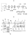
- A is a schematic system configuration diagram of a control system using the hook ceiling of the first embodiment, and B is a schematic block diagram of the hook ceiling and the DC switch of the above. It is a disassembled perspective view which shows one form of the exposure type hook ceiling same as the above. It is an external appearance perspective view which shows one form of the exposure type hook ceiling same as the above. It is an external appearance perspective view which shows an example of an embedded type hook ceiling same as the above.
- A is a schematic system configuration diagram of a control system using the hook ceiling of the second embodiment, and B is a schematic block diagram of the hook ceiling and the DC switch of the above.
- A is an external perspective view showing an embodiment of the above-described exposed type hook ceiling
- B is an external perspective view showing an embodiment of the above-described embedded type hook ceiling
- C is an explanatory view of an address setting unit used in the above.
- It is a schematic block diagram of the hook ceiling and address setting device of Embodiment 3. It is explanatory drawing explaining the operation
- the address setting device used for the address setting is shown
- A is an external view
- B is an example of a setting screen.
- It is an external appearance perspective view which shows one form of an embedded type hook ceiling same as the above. It is a system configuration figure of a direct-current power distribution system using hook ceiling of each embodiment.
- the hook ceiling 1 of the present embodiment is installed on a ceiling surface as a construction surface.
- a hook cap 40 of a DC device 102 that operates by receiving supply of DC power is detachably connected to the hook ceiling 1.
- the hook ceiling 1 supplies DC power to the DC device 102 via the hook cap 40.
- the hooking cap 40 is provided with a hooking blade 41 formed in an L shape in side view.
- FIG. 1A is a schematic system configuration diagram showing a main part of a control system using the hook ceiling 1 of the present embodiment.
- 110 in FIG. 1A is a distribution board installed in the house, and 114 is a DC breaker in the distribution board 110.
- the hook ceiling 1 is connected to the DC supply line Wdc branched from the DC breaker 114.
- a DC switch 50 is provided on the DC supply line Wdc between the hooking ceiling 1 and the DC breaker 114.
- the DC switch 50 is used to turn on or off a DC device 102 such as a lighting fixture connected to the hook ceiling 1.
- the hook ceiling 1 includes a terminal portion 2a to which a DC supply line (DC power supply line) Wdc from the construction surface side is connected, and a terminal portion 2b for feed wiring. Furthermore, the hook ceiling 1 includes a hook connection unit 3, a switch 4, a DLC communication unit 5, and a power supply control unit 6.
- the hook connection portion 3 is configured such that the hook cap 40 included in the DC device 102 is detachably connected. Such a hook connection portion 3 includes a hooking blade receiving portion 22 on which a hooking blade 41 provided on the hooking cap 40 is hooked and locked.
- the switch 4 is provided in the middle of the electric circuit which connects the terminal parts 2a and 2b and the hook connection part 3.
- Such a switch 4 consists of a relay contact and a semiconductor switch, for example.
- the DLC communication unit 5 is configured to perform DLC communication with the outside by superimposing or separating a high-frequency transmission signal on a DC voltage input via the terminal units 2a and 2b.
- the power supply control unit 6 is configured to control on / off of the switch 4 based on a control signal included in a transmission signal received from the outside.
- each of the terminal portions 2a and 2b includes two terminals, a positive electrode and a negative electrode.
- the hook connection part 3 is provided with two hooking blade receiving parts 22 of a positive electrode and a negative electrode.
- the switch 4 is provided only in the electric path connecting the positive terminal of the terminal portions 2 a and 2 b and the positive hooking blade receiving portion 22 of the hook connection portion 3.
- the switch 4 may also be provided in an electric circuit that connects the negative terminal of the terminal portions 2 a and 2 b and the negative hooking blade receiving portion 22 of the hook connection portion 3.
- each of the terminal portions 2a and 2b may include two or more terminals
- the hook connection portion 3 may include two or more hooking blade receiving portions 22.
- the switch 4 may be provided in at least one of the plurality of electric circuits that respectively connect the plurality of terminals of the terminal portions 2 a and 2 b and the plurality of hooking blade receiving portions 22 of the hooking connection portion 3. All of them may be provided with a switch 4.
- the DC switch 50 is disposed on a construction surface such as a wall surface. As shown in FIG. 1B, the DC switch 50 includes a terminal part 51a to which a DC supply line Wdc is connected and a terminal part 51b for a feed wiring. Further, the DC switch 50 includes a DLC communication unit 52, an operation unit 53, an on / off display unit 54, and a control unit 55.
- the DLC communication unit 52 is configured to perform DLC communication with the outside by superimposing or separating a high-frequency transmission signal on a DC voltage input via the terminal units 51a and 51b.
- the operation unit 53 is provided to perform an on / off operation of the corresponding DC device 102.
- the on / off display unit 54 includes a light emitting diode (not shown).
- the on / off display unit 54 is configured to display the on / off state of the corresponding DC device 102 by the lighting state of the light emitting diode.
- the light emitting diode is provided so that the light emission state can be visually recognized from the front surface of the DC switch 50.
- the control unit 55 is configured to perform general control of each unit.
- the control unit 55 of the DC switch 50 performs the above-described on / off display unit 54 based on the monitoring signal received from the corresponding (target to be controlled) hooking ceiling 1. Turn on the light emitting diode. Thereby, the off display of the DC device 102 and the position display of the DC switch 50 are performed. In this state, when an ON operation is performed by the operation unit 53 of the DC switch 50, an ON operation signal is output from the operation unit 53 to the control unit 55.
- the control unit 55 When receiving the ON operation signal, the control unit 55 causes the DLC communication unit 52 to transmit a transmission signal including a control signal for lighting the DC device 102 to the corresponding catching ceiling 1.
- the DLC communication unit 5 receives the control signal included in the transmission signal.
- the power supply control unit 6 closes the switch 4 based on the control signal.
- DC power is supplied from the catch ceiling 1 to the DC device 102 and the lighting DC device 102 is turned on.
- the power supply control unit 6 causes the switch 4 to close, and simultaneously transmits a monitoring signal for notifying the closed state of the switch 4 from the DLC communication unit 5 to the corresponding DC switch 50.
- the control unit 55 controls the on / off display unit 54 based on the monitoring signal included in the transmission signal.
- the monitoring signal since the switch 4 is in a closed state, the control unit 55 turns off the light emitting diode of the on / off display unit 54. That is, the fact that the light emitting diode of the on / off display unit 54 is turned off indicates that the DC device 102 is turned on.
- an off operation signal is output from the operation unit 53 to the control unit 55.
- the control unit 55 receives the off operation signal, the control unit 55 causes the DLC communication unit 52 to transmit a transmission signal including a control signal for turning off the DC device 102 to the corresponding catching ceiling 1.
- the DLC communication unit 5 receives the control signal included in the transmission signal.
- the power supply control unit 6 opens the switch 4 based on the control signal. As a result, the power supply from the catch ceiling 1 to the DC device 102 is cut off, and the lighting DC device 102 is turned off.
- the power supply control unit 6 opens the switch 4 and simultaneously transmits a monitoring signal for notifying the open state of the switch 4 from the DLC communication unit 5 to the corresponding DC switch 50.
- the control unit 55 controls the on / off display unit 54 based on the monitoring signal included in the transmission signal.
- the control unit 55 turns on the light emitting diode of the on / off display unit 54. That is, when the light emitting diode of the on / off display unit 54 is lit, the DC device 102 is turned off.
- the DLC communication unit 5 when the transmission signal is transmitted from the outside superimposed on the DC voltage supplied from the DC supply line Wdc from the construction surface side, the DLC communication unit 5 is connected to the DC. A transmission signal superimposed on the voltage is received. And the electric power feeding control part 6 turns on / off the electric power feeding to the hooking blade receiving part 22 and 22 based on the control signal contained in this transmission signal. Therefore, the power supply to the DC device 102 connected to the hook connection unit 3 can be turned on / off by the control signal included in the transmission signal superimposed on the DC voltage.
- the DC supply line Wdc has to be connected to the terminal portions 2a and 2b of the hook ceiling 1, and it is not necessary to wire the transmission signal separately from the DC supply line Wdc. Therefore, wiring saving and construction can be realized (wiring saving can be achieved and the labor of construction can be reduced). Furthermore, if the DC device 102 is connected to the hook ceiling 1 of the present embodiment, on / off of the DC device 102 can be controlled by turning on / off the power supply from the hook ceiling 1 to the DC device 102. Therefore, the DC device 102 to be controlled is not limited to a dedicated DC device having a communication function. Therefore, the DC device 102 to be controlled can be freely selected or replaced.
- the hook ceiling 1 of this embodiment is provided with the container 11 and the terminal cover 12, as shown in FIG. 2 and FIG.
- the vertical direction in FIG. 2 will be described as the vertical direction of the hooking ceiling 1 in order to simplify the description.
- the vessel body 11 is formed in a bottomed cylindrical shape with an upper surface opened.
- the container 11 is constructed with the upper surface in contact with the ceiling surface (attached to the ceiling surface).
- the terminal cover 12 is formed in a disk shape.
- the terminal cover 12 is inserted into the body 11 from the upper surface side of the body 11.
- the container 11 and the terminal cover 12 are molded articles made of a thermosetting resin (for example, a melamine phenol resin or a polyester resin). By using a melamine phenol resin or a polyester resin, the container 11 and the terminal cover 12 have flame retardancy.
- the container 11 and the terminal cover 12 are coupled by an assembly screw 13 that is a tapping screw. Cutouts 12 a are formed at two locations around the periphery of the terminal cover 12. On the other hand, a cylindrical portion 11 a is formed on the inner surface of the peripheral portion of the vessel body 11. The terminal cover 12 is positioned with respect to the body 11 by fitting the notch 12a into the cylindrical portion 11a.
- a pair of standing walls 14 project from the inner surface of the bottom wall of the container 11.
- the terminal cover 12 is placed on the standing wall 14.
- the assembly screw 13 is screwed into the hole 14 a of the standing wall 14 through the terminal cover 12.
- the container 11 and the terminal cover 12 are combined.
- the container body 11, the terminal cover 12, and the standing wall 14 are arranged so that the upper surface of the terminal cover 12 is positioned below the upper surface of the container body 11. Dimensional relationships are set.
- Tube portions 11 a are formed at two locations on the inner peripheral surface of the peripheral wall of the container 11.
- An insertion hole 15 that penetrates the container body 11 up and down is formed in the cylindrical portion 11a.
- the container body 11 can be fixed to the ceiling surface by screwing a fixing screw (not shown) inserted into the insertion hole 15 from the lower surface side of the container body 11 into the ceiling surface.
- the inside of the container 11 is divided into two by a partition wall 16 projecting from the inner surface of the bottom wall of the container 11.
- two storage chambers 17 are provided inside the container body 11.
- a receiving piece 16a protrudes from the central portion of the partition wall 16 in the longitudinal direction so as to go to both sides.
- support ribs 16b are provided at both ends in the longitudinal direction of the partition wall 16 so as to extend toward both sides.
- a projecting base 18 is provided on the inner side surface of the bottom wall of the container body 11 so as to be located on the opposite side of the partition wall 16 with respect to the support rib 16b.
- hooking blade insertion ports 19 are opened in the peripheral portion of the bottom wall of the container 11.
- the hooking blade insertion opening 19 is formed in a substantially arc shape.
- the hooking blade 41 of the hooking cap 40 is inserted into the hooking blade insertion port 19.
- the hooking blade insertion openings 19, 19 are formed on a circumference centering on the center of the bottom wall of the container 11.
- Each hook plug insertion port 19 includes a wide portion 19a that is wider than the other portion on one end when the hook cap 40 is rotated counterclockwise in the direction shown in FIG.
- the wide part 19a protrudes inward with respect to the narrow part 19b which is another site
- the hooking blade 41 When inserting the hooking blade 41 into the hooking blade insertion slot 19, first, the hooking blade 41 is inserted into the wide portion 19a. Thereafter, the hook cap 40 is rotated clockwise in FIG. Thereby, the front-end
- a hooking blade receiving part 22 is provided in the narrow part 19 b of the hooking blade insertion slot 19.
- the hook connecting blade 3 is constituted by the hook plug inserting port 19 and the hook plug receiving part 22.
- the shape and dimensions of the hooking blade insertion ports 19 and 19 are set to be different from those of the hooking ceiling for the AC power supply.
- One of the hooking blade insertion openings 19 and 19 is for the positive electrode, and the other is for the negative electrode.
- the hook plug blade insertion port 19 for the positive electrode and the hook plug blade insertion port 19 for the negative electrode are formed in an asymmetric shape with respect to the center of the bottom wall. This is to prevent the hooking blade 41 from being inserted with a wrong polarity.
- the hooking blade 41 is also formed in an asymmetric shape for the positive electrode and the negative electrode in accordance with the shape of the hooking blade insertion port 19.
- the hooking blade receiving part 22 is made of sheet metal.
- the hooking blade receiving part 22 has a blade receiving spring 22 a that holds the tip of the hooking blade 41.
- the hooking blade receiving part 22 is housed in the container 11 so that the blade receiving spring 22 a is along the hooking blade insertion port 19. Further, the tip of the blade receiving spring 22a facing the wide portion 19a of the hooking blade insertion slot 19 is an inclined surface that rises from the tip side. This makes it easy for the hooking blade 41 to ride on the blade receiving spring 22a. Therefore, when the leading end of the hooking blade 41 is introduced into the narrow portion 19b, the leading end of the hooking blade 41 rides on the upward inclined surface of the blade receiving spring 22a.
- the hooking blade 41 is hooked and held by the blade receiving spring 22a.
- terminal fittings 20 are accommodated in the two storage chambers 17 of the container 11 respectively.
- the terminal fitting 20 is used for connecting a power supply line of a DC power source.
- the terminal fitting 20 is formed in a substantially U shape having a pair of terminal plates 20a that abut on the support ribs 16b, and a connecting piece 20b that connects between one side edges of both terminal plates 20a.
- the terminal fitting 20 is formed using sheet metal.
- the terminal fitting 20 described above is housed in the container body 11 so as to stand on the inner surface of the bottom wall of the container body 11.
- a locking spring 32 is disposed between the receiving piece 16 a and the terminal plate 20 a in each storage chamber 17.
- the locking spring 32 has a contact piece 32a formed by bending one end of the belt plate into an S shape and a locking piece 32b formed by bending the other end into a J shape.
- the lock spring 32 is arranged so that the contact piece 32a and the lock piece 32b are opposed to the terminal plate 20a.
- the locking spring 32 is arranged so that the locking piece 32b faces up and the contact piece 32a faces down.
- the power supply line When connecting the power supply line (DC power supply line) to the terminal portion 2a, the power supply line may be inserted into the body 11 from the wire insertion port 33 formed in the terminal cover 12. If it does in this way, the core wire of a power wire can be clamped between the contact piece 32a and the locking piece 32b, and the terminal board 20a. At this time, the contact piece 32a comes into contact with the core wire of the power supply line to ensure an electrical connection state. Further, the leading edge of the locking piece 32b bites into the core of the power supply line, and thereby the power supply line is held so as not to come off.
- the terminal portions 2 a and 2 b are configured by terminals of a so-called quick connection terminal structure using the terminal fitting 20 and the lock spring 32.
- a release button 31 is disposed in the body 11.
- the release button 31 is used to remove the power line held using the terminal plate 20a and the lock spring 32.
- the release button 31 includes an operation unit 31a and pressing pieces 31b provided at both ends of the operation unit 31a. That is, the release button 31 is formed in a shape in which a pair of pressing pieces 31b are continuously and integrally connected by the operation portion 31a.
- the operation unit 31 a is placed on the central base 18 a of the projecting base 18.
- the terminal cover 12 is provided with an operation opening 12b including a notch for exposing the operation portion 31a.
- the pressing pieces 31b are located on both sides of the partition wall 16, respectively.
- the front end portion of each pressing piece 31 b is in contact with a part of the locking piece 32 b of the pair of locking springs 32.
- the pressing piece 31b is disposed so as to advance and retract through the insertion notch 20c provided in the terminal fitting 20.
- a tip end portion of a jig such as a minus driver is inserted into the operation opening portion 12b.
- the operation portion 31a may be pressed toward the center of the body 11 with the tip of the inserted jig.
- the pressing piece 31b bends the pair of locking pieces 32b in a direction to separate them from the terminal plate 20a, so that the locking piece 32b is detached from the power line. Therefore, the power supply line can be pulled out as it is.
- the release button 31 is disposed so as to straddle both the terminal fittings 20. Therefore, one release button 31 can simultaneously bend the locking pieces 32b of the two locking springs 32 having different polarities. That is, two power lines can be disconnected at the same time with one release button 31 and the operability is good.
- a printed wiring board (not shown) is stored in the container 11 so as to straddle both the storage chambers 17. Circuits such as the switch 4, the DLC communication unit 5, and the power supply control unit 6 shown in FIG. 1B are formed on the printed wiring board. Moreover, the terminal metal fitting 20 and the hooking blade receiving part 22 are soldered to the printed wiring board.
- the hook ceiling 1 of the present embodiment When the above-described hook ceiling 1 of the present embodiment is installed on the ceiling surface, a fixing screw (not shown) is screwed on the ceiling surface through the insertion hole 15 with the upper surface of the body 11 in contact with the ceiling surface. Just enter.
- the hook ceiling 1 of this embodiment can be easily installed only by forming a through hole for passing a power line on the ceiling surface.
- the hook ceiling 1 shown in FIG. 2 and FIG. 3 is an exposed type hook ceiling constructed in a state where the upper surface of the vessel 11 is in contact with the ceiling surface.
- the technical idea of the present invention can also be applied to an embedded hook sealing as shown in FIG.
- the hook ceiling shown in FIG. 4 is constructed in a state where the upper portion of the vessel 11 is embedded in an embedded hole (not shown) provided on the ceiling surface.
- Embodiment 2 A second embodiment of the present invention will be described with reference to FIGS.
- individual addresses are set for the hook ceiling 1 and the DC switch 50 described in the first embodiment.
- the DC device 102 connected to the corresponding address ceiling ceiling 1 is turned on / off.
- symbol is attached
- FIG. 5A is a schematic system configuration diagram of a control system using the hook ceiling 1 of the present embodiment.
- Two hooking ceilings 1 and three DC switches 50 are connected to the DC supply line Wdc branched from the DC breaker 114.
- Each catch ceiling 1 is connected to a lighting DC device 102.
- the two hooking ceilings 1 are denoted by reference numerals 1A and 1B as necessary in order to distinguish them.
- reference numerals 50A, 50B, and 50C as necessary.
- reference numerals 102A and 102B in order to distinguish the two DC devices 102.
- the hook ceiling 1 includes a terminal portion 2a to which a DC supply line (DC power supply line) Wdc from the construction surface side is connected, and a feed wiring terminal portion 2b. Furthermore, the hook ceiling 1 includes a hook connection unit 3, a switch 4, a DLC communication unit 5, a power supply control unit 6, and an address setting unit 7.
- the hook connection portion 3 is configured such that the hook cap 40 included in the DC device 102 is detachably connected. Such a hook connection portion 3 includes a hooking blade receiving portion 22 on which a hooking blade 41 provided on the hooking cap 40 is hooked and locked.
- the switch 4 is provided in the middle of the electric circuit which connects the terminal parts 2a and 2b and the hook connection part 3.
- Such a switch 4 consists of a relay contact and a semiconductor switch, for example.
- the DLC communication unit 5 is configured to perform DLC communication with the outside by superimposing or separating a high-frequency transmission signal on a DC voltage input via the terminal units 2a and 2b.
- the power supply control unit 6 is configured to control on / off of the switch 4 based on a control signal included in a transmission signal received from the outside.
- the address setting unit 7 is provided for setting its own address.
- a dip switch 7a having a plurality of bits (for example, 6 bits) as shown in FIG. 6C is used as the address setting unit 7.
- the dip switch 7a is exposed on the lower surface of the container 11 as shown in FIGS. 6A and 6B.
- “1” is set as the unique address in the address setting unit 7 of the hook ceiling 1A
- “2” is set as the unique address in the address setting unit 7 of the hook ceiling 1B. To do.
- the DC switch 50 is disposed on a construction surface such as a wall surface. As shown in FIG. 5B, the DC switch 50 includes a terminal portion 51a to which the DC supply line Wdc is connected and a terminal portion 51b for feed wiring. Furthermore, the DC switch 50 includes a DLC communication unit 52, an operation unit 53, an on / off display unit 54, a control unit 55, and an address setting unit 56.
- the DLC communication unit 52 is configured to perform DLC communication with the outside by superimposing or separating a high-frequency transmission signal on a DC voltage input via the terminal units 51a and 51b.
- the operation unit 53 is provided to perform an on / off operation of the corresponding DC device 102.
- the on / off display unit 54 includes a light emitting diode (not shown).
- the on / off display unit 54 is configured to display the on / off state of the corresponding DC device 102 by the lighting state of the light emitting diode.
- the light emitting diode is provided so that the light emission state can be visually recognized from the front surface of the DC switch 50.
- the control unit 55 is configured to perform general control of each unit.
- the address setting unit 56 is provided to set its own address and the address of the hooking ceiling 1 to be controlled.
- the address setting unit 56 of the DC switch 50A is set with the address “1” of the hook ceiling 1A as the control target address.
- the address “2” of the hook ceiling 1B is set as an address to be controlled.
- two addresses, ie, an address “1” of the hook ceiling 1A and an address “2” of the hook ceiling 1B are set as addresses to be controlled.
- the control unit 55 of each of the DC switches 50A to 50C displays their on / off display based on the monitoring signal received from the corresponding hook ceiling 1A or 1B.
- the light emitting diode of the unit 54 is turned on. Thereby, the off display of the DC devices 102A and 102B and the position display of the DC switches 50A to 50C are performed.
- the control unit 55 causes the DLC communication unit 52 to transmit the transmission signal (first transmission signal) to the catch ceiling 1.
- the first transmission signal includes the address of the corresponding ceiling ceiling 1 ⁇ / b> A set in the address setting unit 56 and the control signal for lighting the DC device 102.
- the first transmission signal transmitted by the DC switch 50A is transmitted to the catch ceilings 1A and 1B via the DC supply line Wdc.
- the power supply control unit 6 confirms whether or not the received first transmission signal is addressed to itself. That is, the power supply control unit 6 compares the address included in the received first transmission signal with its own address set in the address setting unit 7. As a result, if both do not match, the power supply control unit 6 discards the received first transmission signal. On the other hand, when both match, the power supply control unit 6 controls the switch 4 based on the control signal included in the received first transmission signal.
- the catch ceiling 1A both coincide with each other, and the received first transmission signal includes a control signal for lighting the DC device 102. Therefore, the power feeding control unit 6 of the hook ceiling 1A closes the switch 4.
- the power supply controller 6 closes the switch 4. Thereby, DC power is supplied from the catch ceiling 1A to the DC device 102A, and the DC device 102A is turned on.
- the power supply control unit 6 closes the switch 4 and simultaneously transmits the second transmission signal from the DLC communication unit 5 to the DC switch 50.
- the second transmission signal includes a monitoring signal for notifying the closed state of the switch 4 and its own address set by the address setting unit 7.
- the control unit 55 checks the address of the received second transmission signal. That is, the control unit 55 compares the address included in the received second transmission signal with the address set in the address setting unit 56. As a result, if the two do not match, the control unit 55 discards the received second transmission signal. On the other hand, if the two match, the control unit 55 controls the on / off display unit 54 based on the monitoring signal included in the received second transmission signal.
- the received second transmission signal includes a monitoring signal for notifying the closed state of the switch 4.
- the control unit 55 of the DC switch 50A turns off the light emitting diode of the on / off display unit 54.
- the DC switch 50B since the two do not match, the second transmission signal is discarded. Therefore, the light emitting diode of the on / off display portion 54 of the DC switch 50B remains lit.
- the DC switch 50C for example, the light emitting diode corresponding to the DC device 102A of the on / off display unit 54 is turned off, and the light emitting diode corresponding to the DC device 102B remains turned on.
- the control unit 55 When the control unit 55 receives the off operation signal, the control unit 55 causes the DLC communication unit 52 to transmit the transmission signal (third transmission signal) to the catch ceiling 1. At this time, the third transmission signal includes the address of the corresponding ceiling ceiling 1A set in the address setting unit 56 and the control signal for turning off the DC device 102.
- the third transmission signal transmitted by the DC switch 50A is transmitted to the catch ceilings 1A and 1B via the DC supply line Wdc.
- the power supply control unit 6 confirms whether or not the received third transmission signal is addressed to itself. That is, the power supply control unit 6 compares the address included in the received third transmission signal with its own address set in the address setting unit 7. As a result, if the two do not match, the power supply control unit 6 discards the received third transmission signal. On the other hand, when the two match, the power supply control unit 6 controls the switch 4 based on the control signal included in the received third transmission signal.
- the catch ceiling 1A both coincide with each other, and the received third transmission signal includes a control signal for turning off the DC device 102. Therefore, the power feeding control unit 6 of the hook ceiling 1A opens the switch 4.
- the power feeding control unit 6 opens the switch 4. As a result, power supply from the hook ceiling 1A to the DC device 102A is stopped, and the DC device 102A is turned off. In addition, the power supply control unit 6 opens the switch 4 and at the same time transmits a transmission signal (fourth transmission signal) from the DLC communication unit 5 to the DC switch 50.
- the fourth transmission signal includes a monitoring signal for notifying the open state of the switch 4 and its own address set by the address setting unit 7.
- the control unit 55 checks the address of the received fourth transmission signal. That is, the control unit 55 compares the address included in the received fourth transmission signal with the address set in the address setting unit 56. As a result, if the two do not match, the control unit 55 discards the received fourth transmission signal. On the other hand, if the two match, the control unit 55 controls the on / off display unit 54 based on the monitoring signal included in the received fourth transmission signal.
- the received fourth transmission signal includes a monitoring signal for notifying the open state of the switch 4. Therefore, the control unit 55 of the DC switch 50A turns on the light emitting diode of the on / off display unit 54.
- the DC transmission 50B discards the fourth transmission signal because they do not match. Therefore, the light emitting diode of the on / off display portion 54 of the DC switch 50B remains lit. Further, for example, in the DC switch 50C, the light emitting diode corresponding to the DC device 102A of the on / off display unit 54 is lit, and the light emitting diode corresponding to the DC device 102B remains lit.
- the address “2” of the hook ceiling 1B is set in the address setting unit 56 of the DC switch 50B. Therefore, when the operation unit 53 of the DC switch 50B is turned on / off, the DC device 102B is turned on or off through the same processing as described above. Further, both the address “1” of the hook ceiling 1A and the address “2” of the hook ceiling 1B are set in the address setting unit 56 of the DC switch 50C.
- the DC switch 50C sends the address “1” of the hook ceiling 1A, the transmission signal including the control signal, and the address “2” of the hook ceiling 1B. And a transmission signal including a control signal are sequentially sent to the DC supply line Wdc. As a result, the DC devices 102A and 102B are turned on or off through the same processing as described above.
- the address setting unit 7 for setting the own address in each catch ceiling 1 is provided.
- Each DC switch 50 is provided with an address setting unit 56 for setting the address of the hook ceiling 1 to be controlled. Therefore, even when a plurality of hook ceilings 1 are connected to the DC supply line Wdc, the plurality of hook ceilings 1 can be individually identified. Therefore, the power supply to the DC device 102 connected to each hook ceiling 1 can be individually turned on / off.
- the dip switch 7 a constituting the address setting unit 7 is disposed on the lower surface of the container 11. Therefore, even after the hook ceiling 1 is constructed on the ceiling surface, the address can be easily set or changed.
- the address is set using the dip switch 7a.
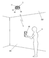
- the address setting is performed using the address setting unit 60 as shown in FIG.
- the address setting unit 7 in this embodiment includes an address receiving unit 7b and an address storage unit 7c.
- the address receiving unit 7b is configured to receive a wireless signal transmitted by the address setting unit 60.
- the address receiving unit 7b is configured to read an address from the received wireless signal and store it in the address storage unit 7c. In this way, the address receiving unit 7b receives the address transmitted from the address setting unit 60 by the wireless signal.
- an infrared signal is used as the wireless signal. Therefore, the address receiving unit 7b includes a light receiving unit (not shown) that receives an infrared signal.
- the address receiving unit 7b is housed in the container 11 with the light receiving unit facing downward. Moreover, as shown in FIG.
- FIG. 10 is an external perspective view of the exposed type hook ceiling 1. Similarly to the embedded type hook ceiling 1 shown in FIG. 7, a light transmitting window 7d is also provided on the lower surface of the container 11 of the hook ceiling 1 shown in FIG.
- the address setting device 60 is a hook ceiling 1 of the present embodiment, other terminals used in a so-called remote monitoring and control system (for example, a monitoring terminal that monitors input of a switch or the like, a control terminal that controls on / off of a load) It is used to set an address etc. in the terminal.
- the address setting unit 60 includes an arithmetic processing unit 61, an input unit 62, a display unit 63, a storage unit 64, and an address transmission unit 65.
- the arithmetic processing unit 61 is configured to perform general control of built-in circuit elements.
- the input unit 62 is provided to perform an address input operation, an address transmission operation, and the like.
- the display unit 63 is composed of a liquid crystal display, for example.
- the display unit 63 is used for displaying the setting contents of the address set by the input unit 62.
- the storage unit 64 is used for storing setting contents.
- the address transmitter 65 is configured to transmit a set value of an address with a wireless
- FIG. 9A shows an external view of the address setting device 60.
- the body 66 of the address setting unit 60 is formed in a size that can be held by a human hand.
- a plurality of operation buttons constituting the input unit 62 are arranged on the lower side of the front surface of the container body 66.
- a display unit 63 is disposed on the upper side of the front surface of the container 66.
- An address transmission unit 65 is disposed on the upper end surface of the container 66.
- FIG. 9B is an example of a setting screen displayed on the display unit 63 of the address setting device 60.
- the input unit 62 can be operated to input setting items such as the address of the hooking ceiling 1 to be set. Thereafter, when a transmission operation is performed, data such as a set address is transmitted from the address transmission unit 65.
- the construction staff A when setting an address in the hook ceiling 1 installed on the ceiling 202 of the room 201, the construction staff A first performs an address input operation using the address setting device 60. Thereafter, when the construction worker A performs a transmission operation, address setting information is transmitted from the address transmission unit 65 of the address setting device 60 by a wireless signal (infrared signal). At this time, the wireless signal transmitted from the address setting device 60 is received by the address receiving unit 7b through the light transmitting window 7d of the hooking ceiling 1. The address received by the address receiving unit 7b is stored in the address storage unit 7c. Therefore, the address setting unit 60 can be used to set the address of the hook ceiling 1. When the wireless signal is an infrared signal, the construction worker A operates the address setting device 60 below the hooking ceiling 1 to be set.
- a wireless signal infrared signal
- the address transmitted by the wireless signal from the address setting unit 60 is received and stored in the address storage unit 7c. Therefore, the address setting operation can be performed from a remote location using the address setting device 60. Therefore, the operation of setting the address of the hook ceiling 1 installed on the ceiling 202 can be easily performed.
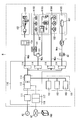
- the hook ceiling 1 described in each of the above embodiments is used in a DC power distribution system as shown in FIG.
- a house H of a detached house is illustrated as a building to which the DC power distribution system is applied.
- the DC power distribution system can also be applied to apartment buildings.
- the house H is provided with a DC power supply unit 101 that outputs DC power and a DC device 102.
- the DC device 102 is a load driven by DC power.
- DC power is supplied to the DC device 102 through the DC supply line Wdc connected to the output end of the DC power supply unit 101.
- a DC breaker 114 is provided between the DC power supply unit 101 and the DC device 102. The DC breaker 114 monitors the current flowing through the DC supply line Wdc, and restricts or cuts off the power supply from the DC power supply unit 101 to the DC device 102 on the DC power supply line Wdc when an abnormality is detected.
- the DC supply line Wdc is also used as a DC power feeding path and a communication path.
- communication between devices connected to the DC supply line Wdc is enabled by superimposing a communication signal that transmits data using a high-frequency carrier wave on the DC voltage.
- This technique is similar to a power line carrier technique in which a communication signal is superimposed on an AC voltage in a power line that supplies AC power.
- the DC supply line Wdc described above is connected to the home server 116 via the DC power supply unit 101.
- the home server 116 is a main device that constructs a home communication network (hereinafter referred to as “home network”).
- the home server 116 communicates with a subsystem constructed by the DC device 102 in the home network.
- an information equipment system K101, lighting systems K102 and K105, an entrance system K103, and a house alarm system K104 are provided as subsystems.
- Each subsystem constitutes an independent distributed system. Therefore, the operation is possible even with the subsystem alone. Further, the subsystem is not limited to the above example.
- the DC breaker 114 is provided in association with the subsystem.
- one DC breaker 114 is provided in association with each of the information equipment system K101, the lighting system K102 and the entrance system K103, the house alarm system K104, and the lighting system K105.
- a connection box 121 is provided. Connection box 121 is configured to divide the system of DC supply line Wdc for each subsystem.
- a connection box 121 is provided between the illumination system K102 and the entrance system K103.
- the information equipment system K101 is composed of information-related DC equipment 102 such as a personal computer, a wireless access point, a router, and an IP telephone.
- the DC device 102 is connected to a DC outlet 131 arranged in advance in the house H (constructed when the house H is constructed) in the form of a wall outlet or a floor outlet.
- the illumination systems K102 and K105 include an illumination-type DC device 102 such as a lighting fixture.
- the lighting system K102 includes a lighting fixture (DC device 102) that is disposed in advance in a house H.
- an instruction to control the lighting fixture of the lighting system K102 can be given using an infrared remote controller.
- the control instruction can also be given using a communication signal from the switch 141 connected to the DC supply line Wdc. That is, the switch 141 has a communication function together with the DC device 102. Further, the control instruction can be given from another DC device 102 in the home network or the home server 116 using a communication signal.
- the instruction content to the lighting fixture includes, for example, lighting, extinguishing, dimming, blinking lighting, and the like.
- the lighting system K105 includes a lighting fixture (DC device 102) connected to the hook ceiling 1 that is arranged in advance on the ceiling.
- the construction contractor may attach a lighting fixture to the hook ceiling 1 at the time of interior construction of the house H, or the householder may attach the lighting fixture himself.
- the entrance system K103 is composed of a DC device 102 for handling visitors and monitoring intruders.
- the home alarm system K104 includes an alarm-type DC device 102 such as a fire detector.
- Any DC device 102 can be connected to the DC outlet 131 and the hooking ceiling 1 described above.
- the DC outlet 131 and the hook ceiling 1 output DC power to the connected DC device 102. Therefore, in the following, when it is not necessary to distinguish between the DC outlet 131 and the hooking ceiling 1, these are referred to as “DC outlets”.
- DC outlets have a connection port (plug-in connection port) into which a contact of the DC device 102 is inserted.
- the container body holds a contact receiver that directly contacts the contact inserted into the connection port. Therefore, the direct current outlet having such a structure supplies power in a contact manner.
- a communication signal can be transmitted through the DC supply line Wdc. Note that not only the DC device 102 but also a DC outlet is provided with a communication function. The contact is provided directly on the DC device 102 or via a connecting line.
- the home server 116 is connected not only to the home network but also to the wide area network NT that constructs the Internet.
- the in-home server 116 is connected to the wide area network NT, the service by the center server (computer server) 200 connected to the wide area network NT can be enjoyed.
- the center server 200 provides, for example, a service that enables monitoring and control of devices connected to the home network through the wide area network NT (including mainly the DC device 102 but also other devices having a communication function). With this service, it is possible to monitor and control devices connected to the home network using a communication terminal (not shown) having a browser function such as a personal computer, Internet TV, or mobile phone.
- a communication terminal not shown
- a browser function such as a personal computer, Internet TV, or mobile phone.
- the home server 116 has both a function of communicating with the center server 200 connected to the wide area network NT and a function of communicating with a device connected to the home network. Further, the home server 116 has a function of acquiring identification information (in this case, an IP address is used) related to a home network device.
- identification information in this case, an IP address is used
- the home server 116 and the center server 200 mediate home devices and communication terminals on the wide area network NT. Therefore, it becomes possible to monitor and control devices in the home using the communication terminal.
- the monitoring request is stored in the center server 200.
- the in-home device periodically performs one-way polling communication, thereby receiving a monitoring or control request from the communication terminal. By such an operation, it becomes possible to monitor and control in-home devices using a communication terminal.
- the home device When an event that should be notified to the communication terminal, such as a fire detection, occurs in the home device, the home device notifies the center server 200 of the occurrence of the event.
- the center server 200 When the center server 200 is notified of the occurrence of an event from a home device, the center server 200 notifies the communication terminal of the occurrence of the event by e-mail.
- the home server 116 automatically detects a device connected to the home network by applying UPnP (Universal Plug and Play).
- the home server 116 includes a display device 117 having a browser function.
- the home server 116 displays a list of detected devices on the display device 117.
- the display device 117 is configured to have a touch panel or other operation unit. Therefore, desired contents can be selected from the options displayed on the screen of the display device 117. Therefore, the user (contractor or householder) of the home server 116 can monitor and control the device on the screen of the display device 117.
- the display device 117 may be provided separately from the home server 116.
- the home server 116 manages information related to device connection.
- the home server 116 grasps the type, function, and address of a device connected to the home network. Accordingly, the devices in the home network can be operated in conjunction with each other.
- the information regarding the connection of the device is automatically detected as described above. In order for the devices to operate in an interlocked manner, the association may be automatically performed according to the attributes owned by the devices themselves.
- an information terminal such as a personal computer can be connected to the home server 116, and devices can be related by using the browser function of the information terminal.
- Each device maintains the relationship of the interlocking operation of the devices. Therefore, the device can operate in an interlocked manner without passing through the home server 116. If the linked operations are related to each other, it becomes possible to turn on or off the lighting fixture that is the device by operating a switch that is the device, for example. In many cases, the association of the interlocking operations is performed within the subsystem, but the association beyond the subsystem is also possible.
- the DC power supply unit 101 basically generates DC power by power conversion of AC power (for example, commercial power supplied from outside the house) AC.
- the AC power supply AC is input to the AC / DC converter 112 including the switching power supply through the main breaker 111.
- the main breaker 111 is attached to the distribution board 110 as an internal unit.
- the DC power output from the AC / DC converter 112 is supplied to each DC breaker 114 through the cooperative control unit 113.
- the DC power supply unit 101 is provided with a secondary battery 162 in consideration of a period in which power is not supplied from the AC power supply AC (for example, a power failure period of a commercial power supply). Further, a solar cell 161 and a fuel cell 163 that generate DC power can be used in combination. In contrast to the main power supply including the AC / DC converter 112, the solar cell 161, the secondary battery 162, and the fuel cell 163 are distributed power sources. In the example shown in FIG. 11, the solar cell 161, the secondary battery 162, and the fuel cell 163 include a circuit unit that controls the output voltage. Further, the secondary battery 162 includes not only discharging but also a circuit unit for controlling charging.
- the solar cell 161 and the fuel cell 163 are not necessarily provided. However, it is desirable to provide the secondary battery 162.
- the secondary battery 162 is charged in a timely manner by a main power source or other distributed power source.
- the secondary battery 162 is discharged not only in a period in which power is not supplied from the AC power supply AC but also in a timely manner as necessary.
- the coordination control unit 113 performs charge / discharge of the secondary battery 162 and coordination between the main power source and the distributed power source. That is, the cooperative control unit 113 functions as a DC power control unit that controls the distribution of power from the main power source and the distributed power source constituting the DC power supply unit 101 to the DC device 102. Note that the outputs of the solar cell 161, the secondary battery 162, and the fuel cell 163 may be converted into AC power and input to the AC / DC converter 112.
- the driving voltage of the DC device 102 is selected from a plurality of types of voltages according to the device. Therefore, it is desirable that the cooperative control unit 113 includes a DC / DC converter that converts a DC voltage obtained from the main power source and the distributed power source into a necessary voltage. Normally, one type of voltage is supplied to one subsystem (or DC device 102 connected to one DC breaker 114). However, a configuration may be adopted in which a plurality of types of voltages are supplied to three subsystems using one or more lines. In addition, when the two-wire DC supply line Wdc is used, a configuration in which the voltage applied between the lines is changed with time can be employed.
- the DC / DC converter may be provided in a plurality of dispersed manners like the DC breaker.
- only one AC / DC converter 112 is provided.
- a plurality of AC / DC converters 112 may be provided in parallel.
- the above-described AC / DC converter 112, cooperative control unit 113, DC breaker 114, solar cell 161, secondary battery 162, and fuel cell 163 are provided with a communication function.
- a cooperative operation for coping with the state of the load including the main power source, the distributed power source and the DC device 102 can be performed.
- the communication signal used for this communication is transmitted in the form of being superimposed on the DC voltage in the same manner as the communication signal used for the DC device 102.
- an AC / DC converter 112 is arranged in the distribution board 110 in order to convert AC power output from the main breaker 111 into DC power.
- the AC / DC converter 112 is not necessarily arranged in the distribution board 110.
- an AC supply line is branched into a plurality of systems by a branch breaker (not shown) provided in the distribution board 110 on the output side of the main breaker 111, and an AC / DC converter is provided in the AC supply line of each system. Also good. That is, you may employ
- the DC power supply unit 101 can be provided in units of floors and rooms of the house H. Therefore, the DC power supply unit 101 can be managed for each system. In addition, the distance of the DC supply line Wdc from the DC device 102 that uses DC power is reduced. Thereby, the power loss due to the voltage drop in the DC supply line Wdc can be reduced. Also, the main breaker 111 and the branch breaker are housed in the distribution board 110, and the AC / DC converter 112, the cooperative control unit 113, the DC breaker 114, and the home server 116 are housed in a separate board from the distribution board 110. Also good.
Abstract
Description
本発明の実施形態1を図1~図4に基づいて説明する。本実施形態の引掛シーリング1は施工面としての天井面に設置される。この引掛シーリング1には、直流電力の供給を受けて動作する直流機器102の引掛キャップ40が着脱自在に接続される。引掛シーリング1は、当該引掛キャップ40を介して直流機器102へ直流電力を供給する。なお、引掛キャップ40には、側面視L字形に形成された引掛栓刃41が設けられている。 (Embodiment 1)
A first embodiment of the present invention will be described with reference to FIGS. The
本発明の実施形態2を図5および図6に基づいて説明する。本実施形態では、実施形態1で説明した引掛シーリング1および直流スイッチ50に個別のアドレスを設定している。本実施形態では、直流スイッチ50の操作に応じて、対応するアドレスの引掛シーリング1に接続された直流機器102をオン/オフする。なお、実施形態1と共通する構成要素には同一の符号を付してその説明は省略する。 (Embodiment 2)
A second embodiment of the present invention will be described with reference to FIGS. In this embodiment, individual addresses are set for the
本発明の実施形態3を図7~図10に基づいて説明する。なお、アドレス設定部7以外の引掛シーリング1の構成は、上述した実施形態1又は2と同様である。よって、共通する構成要素には同一の符号を付してその説明は省略する。 (Embodiment 3)
A third embodiment of the present invention will be described with reference to FIGS. The configuration of the
Claims (3)
- 施工面に露設され、前記器体における施工面側とは異なる面に弧状に開口する複数個の引掛栓刃挿入口が形成される器体と、
前記器体に設けられ前記施工面側から直流電源の給電線が接続される複数個の端子と、
前記複数個の引掛栓刃挿入口とそれぞれ対応するように前記器体内に収納され、前記複数個の端子とそれぞれ電気的に接続される複数個の引掛栓刃受部とを備え、
前記引掛栓刃受部は、前記引掛栓刃挿入口の一端部から挿入された引掛キャップの引掛栓刃が前記引掛栓刃挿入口の他端部に移動したときに、引掛栓刃を引掛保持するように構成されている引掛シーリングにおいて、
前記複数個の端子と前記複数個の引掛栓刃受部との間の電路には、接点が設けられ、
前記器体内には、通信部と、給電制御部とが設けられ、
前記通信部は、前記複数個の端子を介して入力される直流電圧に伝送信号を重畳させて外部との間で通信を行うように構成され、
前記給電制御部は、前記通信部が受信した伝送信号に含まれる制御信号に基づいて、前記接点をオン/オフするように構成されていることを特徴とする引掛シーリング。 A vessel body that is exposed on the construction surface and has a plurality of hooking blade insertion openings that are opened in an arc shape on a surface different from the construction surface side in the vessel body,
A plurality of terminals to which a power supply line of a DC power source is connected from the construction surface side provided in the container body,
A plurality of hooking blade receiving portions that are housed in the container so as to correspond to the plurality of hooking blade insertion ports, and are electrically connected to the terminals, respectively.
The hooking blade receiving part holds the hooking blade when the hooking blade of the hooking cap inserted from one end of the hooking blade insertion port moves to the other end of the hooking blade insertion port. In the hook ceiling that is configured to
A contact point is provided in the electric circuit between the plurality of terminals and the plurality of hooking blade receiving portions,
In the container, a communication unit and a power supply control unit are provided,
The communication unit is configured to communicate with the outside by superimposing a transmission signal on a DC voltage input via the plurality of terminals.
The hooking ceiling, wherein the power supply control unit is configured to turn on / off the contact based on a control signal included in a transmission signal received by the communication unit. - 個別のアドレスを設定するアドレス設定部を備え、
前記給電制御部は、前記通信部が受信した伝送信号に含まれるアドレスが、前記アドレス設定部により設定された自己のアドレスと一致した場合に、前記伝送信号に含まれる制御信号に基づいて前記接点をオン/オフするように構成されていることを特徴とする請求項1記載の引掛シーリング。 It has an address setting section that sets individual addresses.
The power supply control unit, when the address included in the transmission signal received by the communication unit coincides with its own address set by the address setting unit, based on the control signal included in the transmission signal The hook ceiling according to claim 1, wherein the hook ceiling is configured to turn on / off. - 前記アドレス設定部は、外部のアドレス設定器からワイヤレス信号で送信されたアドレスを受信するアドレス受信部と、アドレス受信部により受信されたアドレスを記憶するアドレス記憶部とを備えていることを特徴とする請求項2記載の引掛シーリング。 The address setting unit includes an address receiving unit that receives an address transmitted by a wireless signal from an external address setting unit, and an address storage unit that stores an address received by the address receiving unit. The hook ceiling according to claim 2.
Priority Applications (3)
| Application Number | Priority Date | Filing Date | Title |
|---|---|---|---|
| CN2008801228376A CN101919313A (en) | 2007-12-26 | 2008-12-25 | Hook ceiling |
| US12/810,165 US20100283627A1 (en) | 2007-12-26 | 2008-12-25 | Ceiling-mounted hooking receptacle |
| EP08863655.0A EP2237646A4 (en) | 2007-12-26 | 2008-12-25 | Hook ceiling |
Applications Claiming Priority (2)
| Application Number | Priority Date | Filing Date | Title |
|---|---|---|---|
| JP2007-335176 | 2007-12-26 | ||
| JP2007335176A JP2009158298A (en) | 2007-12-26 | 2007-12-26 | Hook ceiling |
Publications (1)
| Publication Number | Publication Date |
|---|---|
| WO2009081985A1 true WO2009081985A1 (en) | 2009-07-02 |
Family
ID=40801283
Family Applications (1)
| Application Number | Title | Priority Date | Filing Date |
|---|---|---|---|
| PCT/JP2008/073622 WO2009081985A1 (en) | 2007-12-26 | 2008-12-25 | Hook ceiling |
Country Status (5)
| Country | Link |
|---|---|
| US (1) | US20100283627A1 (en) |
| EP (1) | EP2237646A4 (en) |
| JP (1) | JP2009158298A (en) |
| CN (1) | CN101919313A (en) |
| WO (1) | WO2009081985A1 (en) |
Families Citing this family (6)
| Publication number | Priority date | Publication date | Assignee | Title |
|---|---|---|---|---|
| JP5582007B2 (en) * | 2009-12-18 | 2014-09-03 | 東芝ライテック株式会社 | DC power switch device |
| US20130229067A1 (en) * | 2012-03-02 | 2013-09-05 | Ideal Industries, Inc. | Connector having wireless control capabilities |
| BR112015023887A2 (en) * | 2013-03-20 | 2017-07-18 | Koninklijke Philips Nv | direct current (dc) power distribution system for dc power distribution; communication device; communication method; and communication computer program |
| DE202014104416U1 (en) * | 2014-09-17 | 2015-12-18 | Zumtobel Lighting Gmbh | Lighting coupling for lighting system |
| DE102015211454A1 (en) * | 2015-06-22 | 2016-12-22 | Tridonic Gmbh & Co Kg | Sensor supply with a constant current converter for lamps |
| RU2624544C1 (en) * | 2016-06-27 | 2017-07-04 | Немнюгин Андрей Юрьевич | Modular pointing device "mouse" |
Citations (5)
| Publication number | Priority date | Publication date | Assignee | Title |
|---|---|---|---|---|
| JPH0754751B2 (en) | 1986-06-25 | 1995-06-07 | 松下電工株式会社 | Wireless remote dimming control system |
| JP2001035585A (en) | 1999-07-27 | 2001-02-09 | Matsushita Electric Works Ltd | Hooking ceiling device |
| JP2004055473A (en) * | 2002-07-23 | 2004-02-19 | Toshiba Lighting & Technology Corp | Wireless remote control adapter, electric appliance, and lighting system |
| JP2007005019A (en) * | 2005-06-21 | 2007-01-11 | Koizumi Sangyo Corp | Illumination system |
| JP2007122993A (en) * | 2005-10-27 | 2007-05-17 | Matsushita Electric Ind Co Ltd | Illumination apparatus connector and its program |
Family Cites Families (11)
| Publication number | Priority date | Publication date | Assignee | Title |
|---|---|---|---|---|
| DE3853005D1 (en) * | 1988-10-24 | 1995-03-23 | Siemens Ag | Transmission system. |
| DE29701412U1 (en) * | 1997-01-28 | 1998-05-28 | Zumtobel Licht | Device for transmitting information via power supply lines |
| US6714128B2 (en) * | 2001-05-17 | 2004-03-30 | David C. Abbe | Motor vehicle lighting system |
| US20040100151A1 (en) * | 2002-11-06 | 2004-05-27 | Smyth Brain John | Wireless in-line low-voltage controller |
| SE527381C3 (en) * | 2003-04-14 | 2006-03-21 | Linnman Elektronik Ab | Common fieldbus for data and energy transfer |
| DE102004002017B4 (en) * | 2004-01-14 | 2019-12-12 | Tridonic Gmbh & Co Kg | Control of control gear for lamps using switching modulation of a DC bus |
| DE102004002016A1 (en) * | 2004-01-14 | 2005-08-04 | Tridonicatco Gmbh & Co. Kg | Central supply via several DC output circuits |
| DE102004002026A1 (en) * | 2004-01-14 | 2005-08-04 | Tridonicatco Gmbh & Co. Kg | Control of lamp operating devices via a modulated DC bus |
| US7355523B2 (en) * | 2004-04-15 | 2008-04-08 | Alberto Sid | Remote controlled intelligent lighting system |
| DE102004026468A1 (en) * | 2004-05-29 | 2005-12-22 | Daimlerchrysler Ag | Data transmission on power supply lines |
| US20060061329A1 (en) * | 2004-09-17 | 2006-03-23 | Sony Corporation | Method and apparatus for a power line communication (PLC) network |
-
2007
- 2007-12-26 JP JP2007335176A patent/JP2009158298A/en not_active Withdrawn
-
2008
- 2008-12-25 WO PCT/JP2008/073622 patent/WO2009081985A1/en active Application Filing
- 2008-12-25 US US12/810,165 patent/US20100283627A1/en not_active Abandoned
- 2008-12-25 CN CN2008801228376A patent/CN101919313A/en active Pending
- 2008-12-25 EP EP08863655.0A patent/EP2237646A4/en not_active Withdrawn
Patent Citations (5)
| Publication number | Priority date | Publication date | Assignee | Title |
|---|---|---|---|---|
| JPH0754751B2 (en) | 1986-06-25 | 1995-06-07 | 松下電工株式会社 | Wireless remote dimming control system |
| JP2001035585A (en) | 1999-07-27 | 2001-02-09 | Matsushita Electric Works Ltd | Hooking ceiling device |
| JP2004055473A (en) * | 2002-07-23 | 2004-02-19 | Toshiba Lighting & Technology Corp | Wireless remote control adapter, electric appliance, and lighting system |
| JP2007005019A (en) * | 2005-06-21 | 2007-01-11 | Koizumi Sangyo Corp | Illumination system |
| JP2007122993A (en) * | 2005-10-27 | 2007-05-17 | Matsushita Electric Ind Co Ltd | Illumination apparatus connector and its program |
Non-Patent Citations (1)
| Title |
|---|
| See also references of EP2237646A4 * |
Also Published As
| Publication number | Publication date |
|---|---|
| JP2009158298A (en) | 2009-07-16 |
| US20100283627A1 (en) | 2010-11-11 |
| CN101919313A (en) | 2010-12-15 |
| EP2237646A4 (en) | 2015-01-07 |
| EP2237646A1 (en) | 2010-10-06 |
Similar Documents
| Publication | Publication Date | Title |
|---|---|---|
| US8210866B2 (en) | Outlet and connector | |
| WO2009081951A1 (en) | Outlet and plug | |
| WO2009081985A1 (en) | Hook ceiling | |
| JP5027642B2 (en) | Lighting control system | |
| JP2010040389A (en) | Wiring device, and feeding system using wiring device | |
| JP2009157651A (en) | Wiring instrument | |
| JP4974868B2 (en) | DC connection device | |
| JP5032969B2 (en) | DC outlet | |
| JP2009146777A (en) | Dc connecting device | |
| JP2009146780A (en) | Dc connecting device | |
| JP5032292B2 (en) | Catch ceiling | |
| JP2009142012A (en) | Direct-current power distribution system | |
| JP2009146779A (en) | Dc connecting device | |
| JP2009146783A (en) | Dc connecting device | |
| JP2009146827A (en) | Dc receptacle | |
| JP4966180B2 (en) | Power distribution system | |
| JP2009146778A (en) | Dc connecting device | |
| JP2009158299A (en) | Hook ceiling | |
| JP2009159653A (en) | Dc power distribution system | |
| JP5086794B2 (en) | DC power supply device and lighting apparatus | |
| JP2009165250A (en) | Dc power distribution system | |
| JP2009151949A (en) | Dc receptacle | |
| JP2009158301A (en) | Hook ceiling | |
| JP2009159728A (en) | Dc power distribution system | |
| JP2009163962A (en) | Emergency lighting system |
Legal Events
| Date | Code | Title | Description |
|---|---|---|---|
| WWE | Wipo information: entry into national phase |
Ref document number: 200880122837.6 Country of ref document: CN |
|
| 121 | Ep: the epo has been informed by wipo that ep was designated in this application |
Ref document number: 08863655 Country of ref document: EP Kind code of ref document: A1 |
|
| NENP | Non-entry into the national phase |
Ref country code: DE |
|
| WWE | Wipo information: entry into national phase |
Ref document number: 2008863655 Country of ref document: EP |
|
| WWE | Wipo information: entry into national phase |
Ref document number: 12810165 Country of ref document: US Ref document number: 4934/DELNP/2010 Country of ref document: IN |