WO2009074100A1 - Procédé et appareil d'interpolation d'images, procédé d'acquisition de coefficients d'interpolation - Google Patents
Procédé et appareil d'interpolation d'images, procédé d'acquisition de coefficients d'interpolation Download PDFInfo
- Publication number
- WO2009074100A1 WO2009074100A1 PCT/CN2008/073326 CN2008073326W WO2009074100A1 WO 2009074100 A1 WO2009074100 A1 WO 2009074100A1 CN 2008073326 W CN2008073326 W CN 2008073326W WO 2009074100 A1 WO2009074100 A1 WO 2009074100A1
- Authority
- WO
- WIPO (PCT)
- Prior art keywords
- pixel
- sub
- interpolation
- pixel point
- precision
- Prior art date
- Legal status (The legal status is an assumption and is not a legal conclusion. Google has not performed a legal analysis and makes no representation as to the accuracy of the status listed.)
- Ceased
Links
Classifications
-
- H—ELECTRICITY
- H04—ELECTRIC COMMUNICATION TECHNIQUE
- H04N—PICTORIAL COMMUNICATION, e.g. TELEVISION
- H04N19/00—Methods or arrangements for coding, decoding, compressing or decompressing digital video signals
- H04N19/50—Methods or arrangements for coding, decoding, compressing or decompressing digital video signals using predictive coding
- H04N19/59—Methods or arrangements for coding, decoding, compressing or decompressing digital video signals using predictive coding involving spatial sub-sampling or interpolation, e.g. alteration of picture size or resolution
-
- H—ELECTRICITY
- H04—ELECTRIC COMMUNICATION TECHNIQUE
- H04N—PICTORIAL COMMUNICATION, e.g. TELEVISION
- H04N19/00—Methods or arrangements for coding, decoding, compressing or decompressing digital video signals
- H04N19/50—Methods or arrangements for coding, decoding, compressing or decompressing digital video signals using predictive coding
- H04N19/593—Methods or arrangements for coding, decoding, compressing or decompressing digital video signals using predictive coding involving spatial prediction techniques
Definitions
- the present invention relates to the field of communications technologies, and in particular, to an image interpolation method and apparatus, and an acquisition method of an interpolation coefficient. Background technique
- motion estimation algorithm and motion compensation algorithm are the core technologies of video codec technology.
- the principle of motion estimation is as follows: In the coding, the current matching image block is used as a unit, and a suitable matching block is searched in the reference image; the pixel value corresponding to the image block and the matching block are subtracted to obtain a residual, and the redundancy of the image is eliminated. Remaining information; transforming the residual, eliminating the redundant information again, and quantizing the coefficient of variation, and then performing entropy coding; writing the bit data obtained by entropy coding into the coded stream, and the motion offset is The code is also written into the coded stream.
- the motion offset is the position of the matching block in the reference image minus the position of the current coded image block in the current image.
- the offset can also be called a motion vector.
- the principle of motion compensation is: extracting entropy coding information from the bit data obtained from the coded stream during decoding, and performing entropy decoding; and then performing inverse quantization and inverse transformation to obtain residuals obtained by motion estimation during coding, and coding from Obtaining a motion vector in the code stream; obtaining a corresponding matching block in the reference image according to the motion vector value, adding the matching block and the value of the corresponding reference image pixel point in the residual value to obtain the pixel value after decoding of the current image block.
- the integer pixel point refers to the original pixel point of the original image or the image after encoding and decoding
- the so-called sub-pixel point refers to the pixel point between the whole pixel points obtained by processing a plurality of whole pixel points, that is, in the middle of two integer pixel points.
- the sub-pixel point can be called a half sub-pixel point (hereinafter referred to as 1/2 sub-pixel point), as shown in Figure 1, b, h, j, at two 1/2 sub-pixel points or one integer pixel
- a sub-pixel point between a point and a 1/2 sub-pixel point may be referred to as a quarter-sub-pixel point (hereinafter referred to as 1/4 sub-pixel point), as shown in Figure 1, a, c, d, 1 , f , n, I , k, e , g , m, o.
- the process of obtaining sub-pixels can be called interpolation filtering.
- the pixel point interpolation filtering method determines the sub-pixel precision based search. Effect.
- the complexity of the interpolation method is also a part of the existing video coding and decoding technology.
- 1/4 sub-pixel interpolation method such as 1/4 sub-pixel interpolation in the following scheme 1, and adaptive 1/4 sub-pixel in the following schemes 2 and 3. Interpolation, etc.
- interpolation methods based on 1/2 sub-pixel and 1/4 sub-pixel precision are mainly used, in which the interpolation method and the interpolation coefficient used in interpolation are used. They are all fixed, that is: all image blocks in an image have the same sub-pixel precision-based interpolation method, and the same interpolation method is used for 1/2 sub-pixels and 1/4 sub-pixels at the same position in the image block. And interpolation coefficients.
- interpolation coefficients such as:
- C3, C4, D3, and D4 are integer pixels, and b, h, j are 1/2 sub-pixels to be interpolated between the four integer pixels; a, c, d, 1 , f , n, I , k, e , g , m, o are 1/4 sub-pixel points to be interpolated between the four integer pixels.
- the specific interpolation method of the above sub-pixel points is as follows:
- h (A3-5xB3+2xC3+2xD3-5xE3+F3) /32;
- j (b A -5xb B +2 Oxb+20xb D -5xb E +b F ) / 32 ;
- b A is the 1/2 sub-pixel point between A3 and A4
- b B is the 1/2 sub-pixel point between B3 and B4, and so on.
- H4 is 1/2 sub-pixel between C4 and D4.
- H2 is 1/2 sub-pixel between C2 and D2, and so on.
- n (-7b B +42b+96b D -2b E -b F ) /128; b A is a 1/2 sub-pixel point between A3 and A4, b B is a 1/2 sub-pixel point between B3 and B4, and so on.
- the interpolation coefficient is fixed, and the interpolation method cannot adapt to the change of the texture and structure information of the image.
- the 1/4 sub-pixel point is only captured.
- the simple weighted average of two points greatly reduces the accuracy of the interpolation; for the AVS standard, the four points e, g, m, o also draw only the weighted average of the two similar points.
- the interpolation accuracy is lowered, so that high search accuracy for sub-pixel points cannot be obtained.
- Solution 2 In the current VCEG standard, there is a frame-level adaptive two-dimensional interpolation filtering method, and the specific interpolation method is:
- L is the interpolation coefficient required for each point in the interpolation process.
- all the sub-pixel points are obtained by linearly weighting the entire pixel, wherein a, b, c, d, h, 1 are subjected to one-dimensional interpolation filtering, and other points are Interpolation filtering is performed using 36 integer pixels in a two-dimensional space.
- Two-dimensional interpolation filtering greatly increases the complexity of the encoder and decoder, and when encoding small-sized images, it also needs more integer pixel information, so that the interpolation coefficient information used in the encoded code stream is transmitted. Many, it will increase the burden of the code stream, which will reduce the efficiency of the code stream transmission interpolation coefficient.
- Scheme 3 There is also a frame-level adaptive one-dimensional interpolation filtering method in the current VCEG proposal. On the basis of the above two-dimensional interpolation filtering, the complexity of the interpolation operation is reduced to a certain extent, and only one is used in the interpolation filtering method. Dimensions of the dimension and one-dimensional longitudinal integer pixels are interpolated.
- the specific interpolation method is:
- n [b A ⁇ h ln +b B -h 2n +b c -h 3n +b D -h 4n +b E -h 5n +b F -h 6n +2 7 ]» 8
- ⁇ is the interpolation coefficient required for each point in the interpolation process.
- the one-dimensional interpolation filtering method reduces the complexity of the interpolation operation to a certain extent, but the interpolation method is not fully compatible with the prior art (H.264), and needs to expand some integer pixels.
- this detachable one-dimensional interpolation filtering method uses too many pixels in the vertical direction of the image, in the vertical of the image In the case where the texture information of the pixels in the direction is rich and violent, the efficiency of encoding is lowered.
- Embodiments of the present invention provide an image interpolation method, a device, and an interpolation coefficient acquisition method, to obtain pixel points in horizontal, vertical, and other arbitrary directions, perform interpolation filtering on the pixel to be performed, and improve the precision of pixel interpolation filtering. Improve the search accuracy for pixels and obtain more accurate matching block information in the reference image.
- An image interpolation method wherein the pixels are arranged in a two-dimensional matrix, the horizontal direction is a row, and the vertical direction is a column, including: Obtaining pixel values of integer pixels and/or sub-pixels in a row, a column, or any other direction of the pixel, where the sub-pixel is a pixel between the adjacent pixels;
- the pixel points are interpolated according to the acquired pixel values of the entire pixel and/or sub-pixel points and corresponding interpolation coefficients.
- a method for obtaining an image interpolation coefficient comprising:
- An image interpolation device including:
- a first acquiring module configured to acquire pixel values of integer pixels and/or sub-pixels in a row, a column, or any other direction of the pixel, where the sub-pixel is a pixel between the adjacent pixels
- a second obtaining module configured to obtain a pre-computed interpolation coefficient corresponding to an integer pixel point and an I or a sub-pixel point in a row, a column or any other direction of the pixel point;
- a first calculating module configured to perform interpolation on the pixel points according to the acquired pixel values of the integer pixel and/or the sub-pixel point and corresponding interpolation coefficients.
- the image interpolation method, the device, and the interpolation coefficient acquisition method of the embodiment of the present invention can respectively improve the pixel values of the pixel points in different directions and the corresponding interpolation coefficients to interpolate the respective sub-pixel points.
- the effect is also compatible with existing video codec technology.
- 1 is a schematic diagram of pixel points in sub-pixel interpolation calculation
- Embodiment 1 of an image interpolation method according to the present invention
- Embodiment 2 is a schematic flow chart of Embodiment 2 of an image interpolation method according to the present invention.
- Embodiment 1 of an image interpolation apparatus according to the present invention
- FIG. 5 is a schematic structural diagram of Embodiment 2 of an image interpolation apparatus according to the present invention. detailed description
- the solution of the embodiment of the present invention is to spatially select one-dimensional interpolation filtering techniques for different positions of pixels at different positions, and different directions include horizontal, vertical, and other arbitrary directions, and the one-dimensional interpolation filtering technique of mixing different directions is adopted. It has a good interpolation filtering effect on video images having different texture information, and the image interpolation method can apply interpolation with pixel points in the reference image from the encoding end, and interpolation of pixel points in the reference image from the decoding end.
- FIG. 2 it is a schematic flowchart of Embodiment 1 of an image interpolation method according to the present invention, which includes the following steps:
- Step 101 Obtain pixel values of integer pixels and/or sub-pixel points in a row, a column, or any other direction of the pixel;
- Step 1 02 Obtain the pre-calculated pixel point in the row, column, or any other direction Interpolation coefficients corresponding to integer pixels and sub-pixel points;
- Step 1 03 Perform interpolation on the pixel according to the obtained pixel value of the integer pixel and/or the sub-pixel point and the corresponding interpolation coefficient;
- the pixel points that need to be interpolated may be integer pixels and sub-pixel points.
- the pixel points in any other direction referred to in this embodiment refer to pixel points that are approximately on the same line as the obtained sub-pixel points, including integer pixels and sub-pixel points, and may use only pixel values of the entire pixel point. It is also possible to use only the pixel values of the sub-pixel points, or to use the pixel values of the entire pixel point and the sub-pixel point at the same time.
- the one-dimensional interpolation filtering technique can be used to perform interpolation calculation on the obtained sub-pixel points, and the required sub-pixel points are always more accurate than the whole pixel points and/or sub-pixel points to be utilized. , or the same precision as the sub-pixel point to be utilized.
- the sub-pixels sought can be 1 / 2, 1 / 4, 1 / 8, 1 / 16 sub-pixels, or more precise sub-pixels.
- the pixel values of the pixels in the plurality of directions are calculated by interpolation of the sub-pixel points, the distribution of the texture in the two-dimensional space is fully considered, and the coding efficiency higher than that of the prior art can be obtained;
- the pixel values of the acquired integer pixels and/or sub-pixel points can also achieve good compatibility with the prior art.
- FIG. 3 it is a schematic flowchart of Embodiment 2 of an image interpolation method according to the present invention, which includes the following steps:
- Step 201 Obtain pixel values of integer pixels and/or sub-pixel points in a row, a column, or any other direction of the pixel;
- Step 202 Construct a one-dimensional Wienerhoff equation by using pixels and their rows, columns, or other integer pixels and/or sub-pixels in any direction;
- Step 203 Solving a one-dimensional Wienerhoff equation, and obtaining an interpolation coefficient corresponding to an integer pixel point and an I or a sub-pixel point in a row, a column, or any other direction of the pixel point;
- Step 204 Acquire interpolation coefficients corresponding to integer pixels and/or sub-pixel points
- Step 205 Perform interpolation on the second precision sub-pixel point or another sub-pixel point of the first precision according to the acquired integer pixel point and/or the pixel value of the first-precision sub-pixel point and the corresponding interpolation coefficient.
- the precision described in step 205 is the precision of sub-pixel points between adjacent integer pixels, and the smaller the distance between the sub-pixel points and the adjacent integer pixels, the higher the precision, for example, 1/4 sub-pixel points.
- the accuracy is higher than that of 1/2 sub-pixel, and the accuracy of 1/8 sub-pixel is higher than that of 1/16 sub-pixel.
- the first precision in this embodiment may be 1/2 sub-pixel dots, and the second precision is 1/4 sub-pixel dots.
- the required pixel points and/or sub-pixel points in the horizontal, vertical, and positive and negative 45 degrees directions are used to interpolate the required pixel points, specifically using integer pixels and/or sub-pixel points in each direction.
- the expression for interpolation is:
- the first sub-pixel point is performed according to the acquired pixel values of the M integer pixel points and/or the first precision sub-pixel point and the interpolation coefficient corresponding to the M integer pixel points and/or the first precision sub-pixel point Interpolating, the first sub-pixel point is parallel to the M integer pixel points and/or sub-pixel points, and has higher precision than the M integer pixel points and/or the first precision sub-pixel point, or A precision sub-pixel point with sub-pixel points of equal precision, the interpolation formula is:
- a M is the obtained sum.
- Pixel values for the entire pixel and/or sub-pixel of the peer, ⁇ . , ⁇ is a positive integer for the interpolation coefficient corresponding to each integer pixel and/or sub-pixel point.
- any one of the pixel values obtained by interpolation is obtained by interpolation calculation using a fixed interpolation coefficient and a pixel value of a pixel corresponding to the fixed interpolation coefficient.
- 4 corresponding pixel points are sub-pixel points with lower precision than the first sub-pixel point corresponding to ⁇ , that is, if.
- 4 is 1/2 sub-pixel, but since 4 is also a sub-pixel, the pixel value of this point is also solved by interpolation, but if you first try 4 Interpolation coefficient, then right.
- Finding an adaptive interpolation coefficient will greatly increase the complexity of the codec. Therefore, the following solution can be used to simplify the complexity of the codec.
- the point is interpolated using a preset fixed interpolation coefficient, and the fixed interpolation coefficient is a fixed value, at least a fixed value for a certain period of time. Then use the 4 and other images that have been found Prime point, interpolate ⁇ , at this time.
- the required interpolation coefficient can be an adaptive interpolation coefficient.
- the second sub-pixel point is in the same column as the N integer pixel points and/or sub-pixel points, and has higher precision than the N integer pixel points and/or the first precision sub-pixel point, or A precision sub-pixel point with sub-pixel points of equal precision, the interpolation formula is:
- pixel value of the integer pixel and/or the sub-pixel point is an interpolation coefficient corresponding to each integer pixel and/or sub-pixel point, and N is a positive integer.
- the pixel value obtained by interpolation in any of ⁇ , . is obtained by interpolation calculation using a fixed interpolation coefficient and a pixel value of a pixel corresponding to the fixed interpolation coefficient.
- a positive 45 degree direction a third sub-pixel according to the acquired pixel values of the I integer pixel point and/or the first precision sub-pixel point and the interpolation coefficient corresponding to the I integer pixel point and/or the first precision sub-pixel point Interpolating, the third sub-pixel point being in the positive 45 degree direction with the I integer pixel and/or sub-pixel point, than the I integer pixel point and/or the first precision sub-pixel
- the point precision is high, or sub-pixel points with the same precision as the first-precision sub-pixel point.
- the interpolation formula is:
- c is the interpolation of the third sub-pixel
- ⁇ , C 2 is the pixel value of the integer pixel and/or sub-pixel obtained in the positive 45-degree direction with c
- ⁇ ⁇ ,..., / ⁇ is an interpolation coefficient corresponding to each integer pixel and/or sub-pixel point
- I is a positive integer.
- any of the pixel values obtained by interpolation are obtained by interpolation calculation using a fixed interpolation coefficient and a pixel value of a pixel corresponding to the fixed interpolation coefficient.
- Negative 45 degree direction according to the obtained pixel value of the integer pixel point and/or the first precision sub-pixel point and the interpolation coefficient corresponding to the ⁇ integer pixel point and/or the first precision sub-pixel point to the fourth sub-
- the pixel is interpolated, and the fourth sub-pixel point is in the negative 45-degree direction with the ⁇ integer pixel and/or the sub-pixel point, compared to the ⁇ integer pixel point and/or the first precision Subpixel precision, or
- the interpolation formula is:
- the pixel value obtained by interpolation in any of ⁇ , ⁇ , ., ., ⁇ is obtained by interpolation calculation using a fixed interpolation coefficient and a pixel value of a pixel corresponding to the fixed interpolation coefficient.
- the one-dimensional Wienerhoff equation is established for the pixel points sought and the pixel points in a certain direction, as follows:
- the horizontal equation establishes the following equation:
- s refers to the original image that is currently being encoded, that is, the image to be used in the interpolation process for the pixel points in the reference image, and y is a pixel of the corresponding original image being encoded;
- P Is the corresponding reference image. X + MV X _ FiherOffset , where corresponds to the horizontal motion vector of the (x, y) pixel, FterO# t corresponds to half of the filter length; corresponding to the horizontal interpolation coefficient.
- MV y corresponds to the vertical motion vector of ( , y ) pixel
- FterO# t corresponds to half of the filter length.
- V V c p VVV h P P
- the above calculation method for calculating the interpolation coefficient of the pixel is:
- the one-dimensional Wienerhoff equation is solved, and the interpolation coefficients corresponding to the integer pixels and/or sub-pixel points in the row, column or other arbitrary direction of the pixel to be interpolated are obtained;
- the pixel point interpolation filtering method of the embodiment of the present invention is performed by a specific embodiment. With a detailed description.
- these interpolation coefficients are obtained for the following interpolation filtering of the pixel points in the reference image.
- C4, D3, and D4 are integer pixels in different directions adjacent to C3, and b, h, and j are respectively 1/2 sub-pixels that need to be interpolated between the four integer pixels.
- Points, a, c, d, e, f, g, i, k, 1, m, n, o are 1/4 sub-pixel points that need to be interpolated between the four integer pixels.
- Step 301 Obtain pixel values of integer pixels of the row where the sub-pixels a, b, and c are located, that is, pixel values of Cl, C2, C3, C4, C5, and C6;
- Step 302 Obtain an interpolation coefficient A corresponding to the pre-computed line integer pixel, to distinguish the bottom label of the different interpolation coefficient/;
- Step 303 Calculate the interpolation values of a, b, and c according to the obtained pixel values of the six integer pixels Cl, C2, C3, C4, C5, and C6 and the corresponding interpolation coefficients, as follows:
- a C ⁇ -h la + C2-h 2a + Cl>-h 3a + C -h a + C5-h 5a + C6-h 6a
- ⁇ c C2.h 2c +C3-h 3c +C4.h 4c +C5-h 5c +C6-h 6c ;
- Step 304 Obtain pixel values of integer pixels of columns of sub-pixels a, b, and c, that is, pixel values of A3, B3, C3, D3, E3, and F3;
- Step 305 Acquire an interpolation coefficient corresponding to the pre-computed column-integrated pixel point as a bottom mark that distinguishes different interpolation coefficients/;
- Step 306 Calculate the interpolation of d, h, and 1 according to the obtained pixel values of A3, B3, C3, D3, E3, and F3 and corresponding interpolation coefficients, as follows:
- h (A3 + F3) ⁇ h lh + (B3 + E3) ⁇ h 2h + (C3 + D3) ⁇ h 3h .
- d A3-h ld +B3-h 2d +C3-h 3d + D3-h 4d +E3-h 5d
- Step 307 Obtain pixel values of 1/2 sub-pixel points of the column of 1/2 sub-pixel point j, that is, pixel values of b A , b B , b, b D , b pb F , where b is steps 301 ⁇ 303
- the calculated pixel values of 1/2 sub-pixel points, b A , b B , b D , b pb F are calculated by using the b-like interpolation filtering method, which is calculated by using the entire pixel point on the same side. ;
- Step 308 Acquire an interpolation coefficient i corresponding to a pre-computed column or a row of pixels to distinguish a bottom index of different interpolation coefficients/;
- Step 309 Calculate the interpolation of j according to the acquired pixel values of b A , b B , b, b D , 13 ⁇ 4 , and b F and corresponding interpolation coefficients, as follows:
- Step 310 Obtain pixel values of 1/2 sub-pixel points of the column where the sub-pixel points f and n are located, that is, b A , b B , b, b D , b ⁇ .
- the pixel value of b F is, b A , b B , b, b D , b ⁇ .
- Step 311 Obtain an interpolation coefficient ⁇ i corresponding to a pre-calculated column 1/2 sub-pixel point as a bottom mark for distinguishing different interpolation coefficients h;
- Step 312 Calculate the interpolation of f and n according to the obtained pixel values of b A , b B , b , b D , 13 ⁇ 4 , and b F points and corresponding interpolation coefficients, as follows:
- n b A -h hl +b B -h 2n +bh 3n +b D ⁇ 4 + b E ⁇ h 5n + b F 'h 6n ;
- n , + ⁇ ⁇ + ⁇ ⁇ + ' ⁇ ;
- Step 313 Obtain pixel values of 1/2 sub-pixel points of the row where the sub-pixel points i and k are located, that is, pixel values of H1, H2, h, H4, H5, and H6;
- Step 314 Obtain an interpolation coefficient A corresponding to the pre-calculated row 1/2 sub-pixel point, to distinguish the bottom label of the different interpolation coefficient/;
- Step 315 Calculate the interpolation of i and k according to the obtained pixel values of H1, H2, h, H4, H5, and H6 points and corresponding interpolation coefficients, as follows:
- Step 316 Obtain pixel values of the integer pixel point and the 1/2 sub-pixel point j in the negative 45-degree direction of the sub-pixel point e, o, that is, the pixel values of Al, B2, C3, D4, E5, F6, and j;
- Step 317 Obtain an interpolation coefficient corresponding to the pre-calculated integer pixel point and the 1/2 sub-pixel point in the negative 45-degree direction, and determine a different interpolation coefficient/base label;
- Step 318 Calculate according to the obtained pixel values of Al, B2, C3, D4, E5, F6, and j points and corresponding interpolation coefficients. Interpolation with 0 is:
- Step 319 Obtain pixel values of integer pixels in the positive 45-degree direction and 1/2 sub-pixel points j of the sub-pixel points g and m, that is, pixel values of A6, B5, C4, D3, E2, F1, and j;
- Step 320 Obtain an interpolation coefficient h corresponding to the pre-calculated integer pixel point and the 1/2 sub-pixel point in the positive 45-degree direction, to distinguish the bottom coefficients of different interpolation coefficients/;
- Step 321 Calculate the interpolation of g and m according to the obtained pixel values of A6, B5, C4, D3, E2, F1, and j points and corresponding interpolation coefficients, as follows:
- g A6-h lg +B5-h 2g +C4-h 3g +jh 4g +D3-h 5g ;
- m E2-h 2m +D3-h 3m +jh 4m + C4-h 5m +B5-h 6m ;
- the four quarter-pixel sub-pixels of e, o, g, and m are interpolated when using pixels located in the direction of plus or minus 45 degrees, taking into account the distance comparison of pixels in the positive and negative 45 degrees.
- a 1/2 sub-pixel j adjacent to the 1/4 sub-pixel to be interpolated is introduced, for example, Al, B2, C3, j , D4, E5 calculate the e-point interpolation; also the value of the j-point used in the calculation of the interpolation of e, o, g, m can be from steps 307 ⁇ 309
- One of the two calculation methods described in the paper is obtained.
- a one-dimensional Wienerho with the first precision sub-pixel points (here, three 1 / 2 sub-pixel points b, h, j) and their entire rows, columns or other pixels in any direction Then, the one-dimensional Wienerhoff equation is solved, and the interpolation coefficient values corresponding to the three points of the first precision sub-pixel points b, h, j are obtained; and then, the second-precision sub-pixel point is used ( Here are 12 1/4 sub-pixels of a, c, d, e, f, g, i, k, 1 , m, n, o) and their entire row, column or any other pixel in any direction And/or the first precision sub-pixel point b, h, j constructs a one-dimensional Wienerhoff equation; and then solves the one-dimensional Wienerhoff equation to obtain interpolation coefficient values for interpolating the second precision sub-pixel points.
- the first precision sub-pixel points here, three 1 / 2 sub-pixel points b
- 1/2 sub-pixel point j and 1/4 sub-pixel point f, n, i, k are interpolated, 1/2 sub-pixel point b column or 1 /2 is used.
- n, i, k, b A , b B , b, b D , b E and 1 are used in the calculation.
- the storage medium may be a magnetic disk, an optical disk, a read-only memory (ROM), or a random access memory (RAM).
- FIG. 4 it is a schematic structural diagram of Embodiment 1 of the image interpolation apparatus of the present invention, including: a first acquisition module 1 configured to acquire integer pixels and/or sub-arrays in rows, columns, or any other direction of a pixel point. a pixel value of a pixel, wherein the sub-pixel point is a pixel point between the adjacent integer pixel points;
- a second obtaining module 2 configured to obtain an interpolation coefficient corresponding to an integer pixel and/or a sub-pixel point in a row, a column, or any other direction of the pixel point calculated in advance;
- a first calculating module 3 configured to perform interpolation on pixel points according to pixel values of integer pixels and/or sub-pixel points acquired from the first acquiring module 1 and corresponding interpolation coefficients obtained from the second acquiring module 2 .
- the pixel point interpolation apparatus calculates the interpolation of the pixel points obtained by acquiring pixel points in the horizontal, vertical, and other arbitrary directions, and corresponding interpolation coefficients; respectively, performing different pixel points in multiple directions. Interpolation can improve the effect of interpolation calculation and improve the search accuracy for sub-pixels.
- FIG. 5 it is a schematic structural diagram of Embodiment 2 of the image interpolation apparatus of the present invention.
- the first processing module 21 is further included. , for constructing a one-dimensional Wienerhoff equation by using pixels and their rows, columns or other integer pixels and/or sub-pixels in any direction;
- the second processing module 22 is configured to solve the one-dimensional Wienerhoff equation constructed by the first processing module 21, and obtain interpolation coefficients corresponding to integer pixels and/or sub-pixel points in rows, columns, or other arbitrary directions of the pixel points. , the obtained interpolation coefficient is sent to the second acquisition module 2.
- the second obtaining module 2 can obtain the interpolation coefficients of the two points from the third processing module 23.
Landscapes
- Engineering & Computer Science (AREA)
- Multimedia (AREA)
- Signal Processing (AREA)
- Image Processing (AREA)
Description
图像插值方法、 装置及插值系数的获取方法 本申请要求了 2007年 12月 4日提交的、 申请号为 CN 20071 0195919. 0、 发明名称为 "图像插值方法、 装置及插值系数的获取方法" 的中国申请的优 先权, 其全部内容通过引用结合在本申请中。 技术领域
本发明涉及通信技术领域, 特别涉及一种图像插值方法、 装置及插值系 数的获取方法。 背景技术
在视频编解码技术中, 运动估计算法和运动补偿算法为视频编解码技术 的核心技术。 其中运动估计的原理为: 在编码时以当前编码图像块为单位, 在参考图像中搜索合适的匹配块; 将图像块与匹配块所对应的像素值相减, 得到残差, 消除图像的冗余信息; 将残差经变换, 再次消除冗余信息, 并对 变化系数进行量化后得到的值, 再进行熵编码; 将熵编码获得的比特数据写 入编码码流中, 运动偏移量经编码后也一并写入编码码流中, 运动偏移量即 匹配块在参考图像中的位置减去当前编码图像块在当前图像中的位置, 偏移 量也可称为运动矢量。 运动补偿原理为: 在解码时从编码码流中获得的比特 数据中提取出熵编码信息, 并进行熵解码; 然后再经反量化、 反变换得到编 码时运动估计得到的残差, 并从编码码流中获取运动矢量; 根据运动矢量值 在参考图像中获得相应匹配块, 将匹配块与残差值中对应参考图像像素点的 值相加得到当前图像块解码后的像素值。 由于在编码码流中写入的为当前编 码图像块与匹配块的残差, 当前编码图像块的冗余信息被大幅减少, 极大压 缩了写入编码码流中的信息, 从而提高了编码效率。
在运动估计过程中为了能在参考图像中找到更精确的匹配块, 可进一步 的减少冗余信息, 编 /解码器通常情况下使用基于亚像素精度的搜索。 整像素 点是指原始图像或编码解码之后图像的原始像素点, 所谓亚像素点是指对若 干个整像素点进行处理所得的整像素点间的像素点, 即在两个整像素点中间 的亚像素点可称之为二分之一亚像素点(以下简称: 1/2亚像素点), 如图 1 中的 b, h, j , 在两个 1/2亚像素点或一个整像素点和一个 1/2亚像素点之 间的亚像素点可称之为四分之一亚像素点 (以下简称: 1/4 亚像素点) , 如 图 1中的 a , c , d, 1 , f , n, I , k, e , g , m, o。 获取亚像素点的过程可称 之为插值滤波。 由于基于亚像素精度的搜索可以获得更佳的图像匹配块, 从 而可以进一步减少当前编码图像块的冗余信息, 提高编码效率, 因此, 像素 点插值滤波方法的好坏决定基于亚像素精度的搜索的效果。 另外, 在精度高 的像素点插值滤波中, 其插值方法的复杂度也是现有视频编解码技术所注重 的一个环节。
在视频编解码技术相关的标准中都提出了基于 1/4亚像素的插值方法, 如下述方案一中的 1/4亚像素插值, 下述方案二和三中的自适应 1/4亚像素 插值等。
在目前的视频压缩编码标准中, 如 H. 264/AVC, AVS标准, 主要用到基于 1/2 亚像素和 1/4亚像素精度的插值方法, 其中插值方法及插值中所用到的 插值系数都是固定的, 即: 一幅图像中所有图像块具有相同的基于亚像素精 度的插值方法, 图像块中相同位置的 1/2亚像素点、 1/4亚像素点分别具有 相同的插值方法和插值系数。 如:
方案一: 如图 1所示, C3、 C4、 D3、 D4为整像素点, b, h, j为这四个 整像素点间要插值的 1/2亚像素点; a , c , d, 1 , f , n, I , k, e , g , m, o 为这四个整像素点间要插值的 1 /4亚像素点。 上述亚像素点的具体插值方法 如下:
1/2亚像素点插值为:
b= (Cl-5xC2+2xC3+2xC4-5xC5+C6) /32;
h= (A3-5xB3+2xC3+2xD3-5xE3+F3) /32;
j= (bA-5xbB+2 Oxb+20xbD-5xbE+bF) / 32 ;
其中 bA为 A3与 A4之间的 1/2亚像素点, bB为 B3与 B4之间的 1/2亚像素点, 以此类推。
1/4亚像素点插值为:
a=(C3+b)/2; c=(b+C4)/2; d= (C3+h)/2; l=(h+D3)/2;
f=(b+j)/2; n=(j+bD)/2; i=(h+j)/2; k= (H4+j)/2;
e=(b+h)/2; g=(b+H4)/2; m= (h+bD)/2; o= (bD+H4)/2;
其中 H4为 C4与 D4之间的 1/2亚像素点。
在 AVS标准中, 如图 1所示, 亚像素点的具体插值方法如下:
1/2亚像素插值为:
b= (-C2+5C3+5C4-C5)/8;
h= (-B3+5C3+5D3-E3)/8;
j=(-bB+5b+5bD-bE)/8;
1/4亚像素插值为:
a= (-C1-2C2+96C3+42C4-7C5) /128;
c= (-7C2+42C3+96C4-2C5-C6) /128;
i= (-Hl-2H2+96h+42H4-7H5) /128;
k= (-7H2+42h+96H4-2H5-H6) /128;
其中 HI为 CI与 Dl之间的 1/2亚像素点, H2为 C2与 D2之间的 1/2亚像素 点, 以此类推。
d= (-C1-2C2+96C3+42C4-7C5) /128;
1= (-7C2+42C3+96C4-2C5-C6) /128;
f= (-bA-2bB+96b+42bD-7bE) /128;
n= (-7bB+42b+96bD-2bE-bF) /128;
bA为 A3与 A4之间的 1/2亚像素点, bB为 B3与 B4之间的 1/2亚像素点, 以 此类推。
e=(C3+j)/2; o= (D4+j)/2;
g=(C4+j)/2; m= (D3+j)/2;
在该现有亚像素插值算法中, 插值系数固定不变导致插值的方法不能适 应图像的纹理、 结构信息的变化, 对 H.264/AVC标准, 其 1/4亚像素点由于 仅仅釆取了简单的相近两个点的加权平均, 大大降低了其插值的精度;对 AVS 标准, 其 e, g, m, o四个点同样也仅仅釆取了简单的相近两个点的加权平均, 大大降低了其插值精度, 从而不能获得对亚像素点的较高的搜索精度。
方案二: 在目前的 VCEG标准中, 有一种帧级自适应二维插值滤波方式, 其具体插值方式为:
a^[C\- a+C2-h2a+C -hia+C .h4a+C5-h5a+Ce-h6a+29]»\Q b = [(CI + C6) · b + (C2 + C5) · h2b + (C3 + C4)-h3b+29]»10 c = [Cl-/¾c+C2-/?2c+C3-/¾c + C4-/?4c + C5-/?5c+C6-/?6c+29]»10 d = [A3-hld+B3-h2d+C3-h3d + D3-h4d+E3-h5d+F3-h6d + 29]»\0 l = [A3-hlI+B3-h2I + C3-h3I+D3-h4I+E3-h5I + F3-h6I + 29]»\0 h = [(A3 + F3)-hlh+(B3 + E3)-h2h+(C3 + D3)-h3h+29]»10
(A\ + A6)-hllf + (A2 + A5) · lf + (A3 + A4) · hl3f +
(B\ + B6) · h2lf + (B2 + B5) · h22f + (B3 + BA) · h23f +
(CI + C6)•/¾1/+(C2 + C5)-/¾2/+(C3 + C4) - /¾3/ +
(D\ + D6) . h4 f + (D2 + D5) . h42f + (D3 + DA) . h43f +
(El + E6) · h5lf + (Ε2 + Ε5)· h52f + (E3 + E4) · h53f +
(Fl + F6) · h6lf + (F2 + F5)-h62f + (F3 + F4) · h63f + 2'
()) () ( f f f f5 b4 +b + £465 +b + F4 + E65 +£ + F + ... ·
) () ( () ( f f。 f6 + Fl + 52 C +2 +β4 + b2 + + · - · ·
)()()f+ +≥c+l+4 +l +---- ■
■f +2
() () () f f f f5 D4 +D + £465 +D + F4 + E65 +E + F + . - · . ·
() () () () f f f f f6 C35 + F2 +C3C5 +4 + b + + E3C63 + + F + · . · · ·
() () () ()6.4 + Fl + B23 C +5 +2 +54 + D52 +5 + E2 + .....
() () () () f +.42 + 51 C + +I +.44 + bl5 +.4 + El + · . · · · . 10, 》

A6■hllg+(A5 + B6) . /¾2g + (A4 + C6)■hlig+(AZ + D6) -h,^ + (A2 + E6) . ig +
(A\ + F6) ' ^ + B5 ' h22g + (BA + C5) ' h23g + (S3 + D5) ' h24g + (B2 + E5) ' h25g + g (m + F5) . h26g + C4. /¾3g + (C3 + DA) . h34g + (C2 + EA)- h35g + (CI + FA) . h36g + »10 D3. h44g + (D2 + E3) . h45g + (Dl + F3) . h46g + El . h55g + (El + F2) . h56g +

其中 L为插值过程中各点所需插值系数。
这种二维插值滤波器, 所有的亚像素点都是釆取整像素点的线性加权所 得, 其中对 a, b, c, d, h, 1釆取一维插值滤波方式, 对其他点都利用了二维空 间中的 36个整像素点进行插值滤波。
二维插值滤波大大增加了编码器和解码器的复杂度, 而且在编码小尺寸 图像时, 由于其同样也需要较多的整像素点信息, 从而其编码码流中用来传 输的插值系数信息就很多, 会增加编码码流的负担, 会降低编码码流传输插 值系数的效率。
方案三: 在目前的 VCEG提案中还有一种帧级自适应一维插值滤波方式, 在上述二维插值滤波的基础上一定程度的降低了插值运算的复杂度, 该插值 滤波方式中仅使用一维横向和一维纵向的若干整像素点来进行插值, 其具体 插值方式为:
a = [Ch la + C2. 2a + C3- 3a + C4. 4a + C5- 5a + C6- 6a + 27]»8 b = [(CI + C6) · b + (C2 + C5) · h2b + (C3 + C4) · h3b + 27]»8 c = [Cl-/¾c+C2-/?2c + C3-/¾c + C4-/?4c+C5-/?5c+C6-/?6c+27]»8 h = [(^3 + F3) · h + (B3 + E3) · h2h + (C3 + D3) · h3h +27]»8 j = i(bA +bF - Kj +(bB + bE)- h2J + (bc+bD)- h3J +27]»8 d = [A3-hld+B3-h2d+C3-h3d + D3-h4d+E3-h5d+F3-h6d + 27]»S
/ = [^3·/¾/ +53· h2l + C3-h3I+D3- h4I + E3 · h51 + F3 · h6l + 27]»8
i = [(aA + aF)-hu + (aB + aE)-h2i + (ac + <¾)· ¾,· + 27] » 8
k = [(cA+cF)-hlk + (cB+cE)-h2k + (cc+cD)-h3k + 27]»S
f = [bA-hlf+bB-h2f+bc-h3f + bD-h4f+bE-h5f+bF-h6f + 21]»8
n = [bA■hln+bB-h2n+bc-h3n+bD-h4n+bE-h5n+bF -h6n+27]» 8
e = [(¾ -K + aB - + ac · h3e + aD · hAe + aE · h5e + aF · h6e + 27]»8
m = [(aA - m +aB -h2m + ac -h3m + aD -h4m + aE -h5m + aF -h6m + 2l » S
g = [(cA-hlg+cB-h2g+cc-h3g+cD-h4g+cE-h5g+cF-h6g+21]»8
o = [(c +cc +c£ ·/¾。 + ·/¾。 +27]» 8
其中 ^为插值过程中各点所需的插值系数。
该一维插值滤波方法相对于上述二维插值滤波在一定程度上降低了插值 运算的复杂度, 但这种插值方式与现有技术(H.264)并不能完全兼容, 需要扩 展一些整像素点或亚像素点来完成插值运算; 而且由于其 a、 b、 c这 3个亚 像素点是用水平像素信息进行一维插值, 对 d、 e、 f、 g、 h、 i、 j、 k、 1、 m、 n、 o这 12个亚像素点釆用垂直像素信息进行一维插值, 这种可分离的一维 插值滤波方式用到了图像在垂直方向上的像素点过多, 在图像的垂直方向上 的像素的纹理信息变化比较丰富和剧烈的情况下, 会降低编码的效率。 发明内容
本发明实施例提供一种图像插值方法、 装置及插值系数的获取方法, 以 获得横向、 纵向及其他任意方向上的像素点, 对待求像素点进行插值滤波, 提高像素点插值滤波的精度, 从而提高对于像素点的搜索精度, 获取参考图 像中更精确的匹配块信息。
一种图像插值方法, 所述像素点成二维矩阵式排布, 横向为行, 纵向为 列, 包括:
获取所述像素点所在行、列或其他任意方向上的整像素点和 /或亚像素点 的像素值, 所述亚像素点为相邻的所述整像素点间的像素点;
获取预先计算得出的所述像素点所在行、 列或其他任意方向上的整像素 点和 /或亚像素点对应的插值系数;
根据获取的所述整像素点和 /或亚像素点的像素值及对应的插值系数对 所述像素点进行插值。
一种图像插值系数的获取方法, 包括:
利用待求插值的像素点及其所在行、列或其他任意方向上的整像素点和 / 或亚像素点构建一维维纳霍夫方程;
求解所述一维维纳霍夫方程, 得到所述待求插值的像素点所在行、 列或 其他任意方向上的整像素点和 /或亚像素点对应的插值系数;
获取所述整像素点和 /或亚像素点对应的插值系数。
提供了一种图像插值装置, 包括:
第一获取模块, 用于获取像素点所在行、 列或其他任意方向上的整像素 点和 /或亚像素点的像素值, 所述亚像素点为相邻的所述整像素点间的像素 点;
第二获取模块, 用于获取预先计算得出的所述像素点所在行、 列或其他 任意方向上的整像素点和 I或亚像素点对应的插值系数;
第一计算模块,用于根据获取的所述整像素点和 /或亚像素点的像素值及 对应的插值系数对所述像素点进行插值。
由以上技术方案可知, 本发明实施例的图像插值方法、 装置及插值系数 的获取方法, 通过获取到的不同方向的像素点的像素值及对应插值系数分别 对各个亚像素点进行插值, 可以提高插值滤波的效果, 从而提高对于像素点 的搜索精度; 且充分利用了得出的较低精度的像素点的插值信息来计算较高 精度的像素点插值, 可提高计算的精度, 进一步提高插值滤波的效果, 而且 与现有的视频编解码技术又可兼容。
附图说明
为了更清楚地说明本发明实施例或现有技术中的技术方案, 下面将对实 施例或现有技术描述中所需要使用的附图作简单地介绍, 显而易见地, 下面 描述中的附图仅仅是本发明的一些实施例, 对于本领域普通技术人员来讲, 在不付出创造性劳动性的前提下, 还可以根据这些附图获得其他的附图。
图 1为亚像素插值计算中像素点示意图;
图 2为本发明图像插值方法的实施例一的流程示意图;
图 3为本发明图像插值方法的实施例二的流程示意图;
图 4为本发明图像插值装置的实施例一的结构示意图;
图 5为本发明图像插值装置的实施例二的结构示意图。 具体实施方式
下面将结合本发明实施例中的附图, 对本发明实施例中的技术方案进行 清楚、 完整地描述, 显然, 所描述的实施例仅仅是本发明一部分实施例, 而 不是全部的实施例。 基于本发明中的实施例, 本领域普通技术人员在没有作 出创造性劳动前提下所获得的所有其他实施例 , 都属于本发明保护的范围。
本发明实施例的方案是在空间上针对不同位置的像素点选择不同方向的 一维插值滤波技术, 不同的方向包括有横向、 纵向及其他任意方向, 这种混 合不同方向的一维插值滤波技术, 对具有不同纹理信息的视频图像具有艮好 的插值滤波效果, 该图像插值方法可应用与编码端对参考图像中的像素点的 插值, 和解码端对参考图像中的像素点的插值。
如图 2所示, 为本发明图像插值方法实施例一的流程示意图, 包括如下 步骤:
步骤 101、 获取像素点所在行、 列或其他任意方向上的整像素点和 /或亚 像素点的像素值;
步骤 1 02、 获取预先计算得出的像素点所在行、 列或其他任意方向上的
整像素点和亚像素点对应的插值系数;
步骤 1 03、 根据获取的整像素点和 /或亚像素点的像素值及对应的插值系 数对像素点进行插值;
该需要进行插值的像素点可为整像素点和亚像素点。
本实施例中所说的其他任意方向上的像素点是指与所求亚像素点近似在 同一直线上的像素点, 包括整像素点和亚像素点, 可以仅利用整像素点的像 素值, 也可以仅利用亚像素点的像素值, 或者同时使用整像素点和亚像素点 的像素值。 取得这些像素点的像素值后, 可用一维插值滤波技术对所求亚像 素点进行插值计算,需要求取的亚像素点总是比要利用的整像素点和 /或亚像 素点精度更高, 或者与要利用的亚像素点的精度相同。 其中所求的亚像素点 可以 1 / 2、 1 /4、 1 / 8、 1 / 16亚像素点, 或者更加精确的亚像素点。
本实施例中由于对亚像素点的插值计算釆用了多个方向的像素点的像素 值, 充分考虑了纹理在二维空间的分布, 能够获得比现有技术更高的编码效 率; 而且所获取的整像素点和 /或亚像素点的像素值也可与现有技术达到艮好 的兼容性。
如图 3所示, 为本发明图像插值方法实施例二的流程示意图, 包括如下 步骤:
步骤 201、 获取像素点所在行、 列或其他任意方向上的整像素点和 /或亚 像素点的像素值;
步骤 202、 利用像素点及其所在行、 列或其他任意方向上的整像素点和 / 或亚像素点构建一维维纳霍夫方程;
步骤 203、 求解一维维纳霍夫方程, 得到像素点所在行、 列或其他任意 方向上的整像素点和 I或亚像素点对应的插值系数;
步骤 204、 获取整像素点和 /或亚像素点对应的插值系数;
步骤 205、 根据获取的整像素点和 /或第一精度亚像素点的像素值及对应 的插值系数对第二精度亚像素点或第一精度的另一亚像素点进行插值。
步骤 205中所述的精度为对相邻整像素点间亚像素点的划分精度, 划分 出的亚像素点与其相邻的整像素点距离越小, 精度越高, 例如 1/4亚像素点 的精度比 1/2亚像素点的精度要高, 1/8亚像素点的精度比 1/16亚像素点的 精度要高。 在本实施例中的第一精度可为 1/2亚像素点, 第二精度为 1/4亚 像素点。
例如要用横向、 纵向及正负 45度方向上的整像素点和 /或亚像素点对要 求的像素点进行插值,具体釆用各个方向上的整像素点和 /或亚像素点对像素 点进行插值的表达式为:
横向:根据获取的 M个整像素点和 /或第一精度亚像素点的像素值及与该 M个整像素点和 /或第一精度亚像素点对应的插值系数对第一亚像素点进行插 值, 所述第一亚像素点为与所述 M个整像素点和 /或亚像素点同行的, 比所述 M个整像素点和 /或第一精度亚像素点精度高, 或与第一精度亚像素点同等精 度的亚像素点, 插值公式为:
a = Al.hla+A2.h2a+A3.h3a+...+ AM.hMa , 其中。为第一亚像素点的插值, A,A2,...,AM为获取到的与。同行的整像素点和 /或亚像素点的像素值, Λ。, 为各整像素点和 /或亚像素点对应的插值系数, Μ为正整数。
其中 中任一个通过进行插值得到的像素值,釆用固定插值系数 及与固定插值系数对应的像素点的像素值进行插值计算来获取。 例如: 4对 应的像素点为比 α对应的第一亚像素点精度低的亚像素点, 即若。为 1/4亚像 素点, 4就为 1/2亚像素点, 但是由于 4也为亚像素点, 所以该点的像素值 也要用插值方法进行求解,但是如果先对 4求一次自适应插值系数,再对。求 一次自适应插值系数, 会大大增加编解码的复杂度, 因此, 可以釆取如下的 求解方式来简化编解码的复杂度。 例如, 在求较低精度的亚像素点时, 使用 预先设定好的固定插值系数对该点进行插值, 固定插值系数即为固定不变的 值, 至少是在一定时间内固定不变的值; 然后再利用已经求出的 4及其他像
素点, 对^进行插值, 此时。所需的插值系数可为自适应插值系数。
纵向:根据获取的 N个整像素点和 /或第一精度亚像素点的像素值及与该 N个整像素点和 /或第一精度亚像素点对应的插值系数对第二亚像素点进行插 值, 所述第二亚像素点为与所述 N个整像素点和 /或亚像素点同列的, 比所述 N个整像素点和 /或第一精度亚像素点精度高, 或与第一精度亚像素点同等精 度的亚像素点, 插值公式为:
b = Bl-hlb+B2-h2b+B3-h3b+... + BN-hNb , 其中 6为第二亚像素点的插值 , ^ 为获取到的与 6同列的整像素点和 /或亚像素点的像素值, 为各整像素点和 /或亚像素点对应的插值系数, N为正整数。
其中^ ,. 中任一个通过进行插值得到的像素值, 釆用固定插值系数 及与固定插值系数对应的像素点的像素值进行插值计算来获取。
正 45度方向: 根据获取的 I个整像素点和 /或第一精度亚像素点的像素 值及与该 I 个整像素点和 /或第一精度亚像素点对应的插值系数对第三亚像 素点进行插值,所述第三亚像素点为与所述 I个整像素点和 /或亚像素点同在 正 45度方向上的, 比所述 I个整像素点和 /或第一精度亚像素点精度高, 或 与第一精度亚像素点同等精度的亚像素点, 插值公式为:
。^、' +^-^ + ^-^+…+^-^。 , 其中 c为第三亚像素点的插值 , ς, C2, 为获取到的与 c同在正 45度方向上的整像素点和 /或亚像素点的像 素值, Λε,...,/^为各整像素点和 /或亚像素点对应的插值系数, I为正整数。
其中 ς ,... ,中任一个通过进行插值得到的像素值, 釆用固定插值系数 及与固定插值系数对应的像素点的像素值进行插值计算来获取。
负 45度方向: 根据获取的 Κ个整像素点和 /或第一精度亚像素点的像素 值及与该 Κ 个整像素点和 /或第一精度亚像素点对应的插值系数对第四亚像 素点进行插值 ,所述第四亚像素点为与所述 Κ个整像素点和 /或亚像素点同在 负 45度方向上的, 比所述 Κ个整像素点和 /或第一精度亚像素点精度高, 或
与第一精度亚像素点同等精度的亚像素点, 插值公式为:
d = Dl'hld+D1'hld+D3'h3d+— + DK'hKd , 其中 t 为第三亚像素点的插值, A, A,..., A为获取到的与 同在负 45度方向上的整像素点和 /或亚像素点的像 素值, ,/^,...,/^为各整像素点和 /或亚像素点对应的插值系数, K为正整数。
其中 Α,Α,.,.,Α中任一个通过进行插值得到的像素值,釆用固定插值系数 及与固定插值系数对应的像素点的像素值进行插值计算来获取。
下面介绍下对所求像素点所在行、 列或其他任意方向上的整像素点和亚 像素点对应的插值系数的计算方法。
对所求像素点与利用某方向上的像素点建立一维维纳霍夫方程, 如下: 水平方向建立如下方程方程:
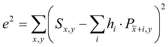
其中 s指的是现在正在进行编码的原始图像, 即对参考图像中的像素点 求取插值过程中要用到的图像, y为对应的正在进行编码的原始图像的某一 个像素点; P指的是对应的参考图像。 的 = X + MVX _ FiherOffset , 其中 对应的是(x,y)像素点的水平方向运动矢量, FterO# t对应的是滤波器长 度的一半; 对应的是水平方向的插值系数。
要获得最佳插值滤波器系数, 需要使 最小, 则必须满足下式:
de
dh
2、
_d_ 、

其中, V e{0;5}, 则得到一维维纳霍夫方程组为: x+k,y
通过解这个 6 χ 6的二维方程组,即可以得到水平方向上对应原始图像的 像素点的插值系数 。
同样对于垂直方向的维纳霍夫方程为:

则得到一维维纳霍夫方程组为:
其中^ = y + MVy- Filter Offset , MVy对应的是 ( , y )像素点的垂直方向运动 矢量, FterO# t对应的是滤波器长度的一半。 对应的是垂直方向的插值系 数。
通过解这个 6 X 6的二维方程组,即可以得到垂直方向插值滤波器系数/^ 对于正负 45度的维纳霍夫方程为:
V V c p =VVV h P P
L-tL-i (i (i) L-tL-iL-i ι ¾+"(!·), >+»!(!·) ¾+/(!·), >+*:(!·)
^ 1 !(i),k(i),m(i),n(i)由 和 45度插值所用的周边像素的位置所决定。 通过解这个 6 X 6的二维方程组, 即可以得到正负 45度方向上的插值系 数 /?,·。
上述求像素点的插值系数的计算方法即为:
首先, 利用待求插值的像素点及其所在行、 列或其他任意方向上的整像 素点和 /或亚像素点构建一维维纳霍夫方程; 上述计算中求了横向、 纵向及正 负 45度方向上的像素点对应的插值系数;
然后, 求解一维维纳霍夫方程, 得到待求插值的像素点所在行、 列或其 他任意方向上的整像素点和 /或亚像素点对应的插值系数;
最后, 获取整像素点和 /或亚像素点对应的插值系数。
下面通过一个具体的实施例对本发明实施例的像素点插值滤波方法进行
伴细说明。
计算得出了各个方向上的所要用到的插值系数后, 获取这些插值系数用 于下面的对参考图像中的像素点的插值滤波。
如图 1所示, 其中 C4、 D3、 D4为与 C3相邻的不同方向上的整像素点, b、 h、 j分别为这四个整像素点间需要进行插值计算的 1/2亚像素点, a、 c、 d、 e、 f、 g、 i、 k、 1、 m、 n、 o为这四个整像素点间需要进行插值计算的 1/4 亚像素点。
计算亚像素点插值为如下步骤:
步骤 301、 获取亚像素点 a、 b、 c所在行的整像素点的像素值, 即 Cl、 C2、 C3、 C4、 C5、 C6的像素值;
步骤 302、 获取预先计算得出的行整像素点对应的插值系数 A,, 为区分 不同插值系数/的底标;
步骤 303、 根据获取的 6个整像素点 Cl、 C2、 C3、 C4、 C5、 C6的像素值 及对应的插值系数, 计算 a、 b、 c的插值, 为:
b = (Cl + C6) - hlb + (C2 + C5) - h2b + (C3 + C4) - b . a = C hla + C2.h2a + C3-h3a + C4.h4a + C5-h5a + C6-h6a. c = C\-hlc+C2-h2c+C -h3c + C -h4c + C5-hic+C6-h6c. 上述公式还可进一步简化为:
b = C\-hlb+ (C2 + C5) · h2b + (C3 + C4) · h3b;
a = C\-hla + C2-h2a + Cl>-h3a + C -ha + C5-h5a + C6-h6a^ c = C2.h2c+C3-h3c+C4.h4c+C5-h5c+C6-h6c;
步骤 304、 获取亚像素点 a、 b、 c所在列的整像素点的像素值, 即 A3、 B3、 C3、 D3、 E3、 F3的像素值;
步骤 305、 获取预先计算得出的列整像素点对应的插值系数 为区分 不同插值系数/的底标;
步骤 306、 根据获取到的 A3、 B3、 C3、 D3、 E3、 F3的像素值及对应的插 值系数, 计算 d、 h、 1的插值, 为:
h = (A3 + F3) · hlh + (B3 + E3) · h2h + (C3 + D3) · h3h . d = A3-hld+B3-h2d+C3-h3d + D3-h4d+E3-h5d+F3-h6d. I = A3. + Β3 ' h21 + C3 ' + D3 ' h41 + E3 · h5l + F3 · h6l . 上述公式还可进一步简化为:
h = (A3 + F3) · hlh + (B3 + E3) · h2h + (C3 + D3) · h3h . d = A3-hld+B3-h2d+C3-h3d + D3-h4d+E3-h5d
l = B3-h2I + C3- h3I + D3 · h4l + E3 · h5I + F3 · h6I;
步骤 307、 获取 1/2亚像素点 j所在列的 1/2亚像素点的像素值, 即 bA、 bB、 b、 bD、 b pbF的像素值, 其中 b为步骤 301 ~ 303计算得出的 1/2亚像素 点的像素值, bA、 bB、 bD、 b pbF为用与 b—样的插值滤波方法, 釆用与其同 行上的整像素点计算得出的;
由于 j点位于 C4、 D3、 D4为与 C3相邻的四个整像素点的中心, 所以对 j 点也可以获取其所在行的 1/2 亚像素点的像素值, 即 Hl、 H2、 h、 H4、 H5 和 H6点的像素值, 其中 h为步骤 304 ~ 306计算得出的 1/2亚像素点的像素 值, Hl、 H2、 H4、 H5和 H6为用与 h—样的插值滤波方法, 釆用与其同列上 的整像素点计算得出的;
步骤 308、 获取预先计算得出的列或行整像素点对应的插值系数 i为 区分不同插值系数/的底标;
步骤 309、 根据获取到的 bA、 bB、 b、 bD、 1¾和 bF的像素值及对应的插值 系数, 计算 j的插值, 为:
j = Α + bF )hy + (bB + bE )h2j +(b + bD )h ;
或者, 根据获取到的 Hl、 H2、 h、 H4、 H5和 H6的像素值及对应的插值系 数, 计算 j的插值, 为:
j = (H1+H6)- hXj + (H2 + H5 ) · h2j +(h + H4)- h3j;
步骤 310、 获取亚像素点 f、 n所在列的 1/2亚像素点的像素值, 即 bA、 bB、 b、 bD、 b^。bF的像素值;
步骤 311、 获取预先计算得出的列 1/2亚像素点对应的插值系数^ i为 区分不同插值系数 h的底标;
步骤 312、 根据获取的 bA、 bB、 b、 bD、 1¾和 bF点的像素值及对应的插值 系数, 计算 f 和 n的插值, 为:
f = bA - lf +bB -h2f +b-h3f +bD -h4f +bE -h5f +bF -h6f;
n = bA-hhl+bB -h2n+b-h3n+bD■ 4 + bE■ h5n + bF 'h6n;
上述公式还可进一步简化为:
f = bA-hlf +bB-h2f + b-h3f +bD-h4f +bE-h5f ; n= , + · Κ + · Κ + ' Κη;
步骤 313、 获取亚像素点 i、 k所在行的 1/2亚像素点的像素值, 即 Hl、 H2、 h、 H4、 H5和 H6的像素值;
步骤 314、 获取预先计算得出的行 1/2亚像素点对应的插值系数 A,, 为 区分不同插值系数/的底标;
步骤 315、 根据获取的 Hl、 H2、 h、 H4, H5和 H6点的像素值及对应的插 值系数, 计算 i和 k的插值, 为:
i = H hu + H2. h2i + h · h3i + H4 · h4i + H5. h5i + H6 · h6i;
k = Hl -hlk+H2 -h2k +h-h3k +H4 -h4k+H5 -h5k +H6 -h6k;
上述公式还可进一步简化为:
i = Hx- hXi + H2. h2j + h . h3i + H4. h4j + H5. h5i;
k = H2-h2k+h-h3t + H4-h4k + H5-h5k+H6-h6k;
步骤 316、 获取亚像素点 e、 o所在负 45度方向上的整像素点和 1/2亚 像素点 j的像素值, 即 Al、 B2、 C3、 D4、 E5、 F6和 j的像素值;
步骤 317、 获取预先计算得出的负 45度方向上的整像素点和 1/2亚像素 点对应的插值系数/^ 为区分不同插值系数/的底标;
步骤 318、 根据获取的 Al、 B2、 C3、 D4、 E5、 F6和 j点的像素值及对应 的插值系数, 计算。和0的插值, 为:
e = A\-hle + B2-h2e+C3- h3e + j · h4e + D4 · h5e + E5 · h6e . o = Blr 'hl。+C3'h10+ ./¾。+£>4. 。+ 5'/¾。+ 6. 。. 上述公式还可进一步简化为:
e = A\-hle + B2-h2e+C3- h3e + j · h4e + D4 · h5e;
o = C3-h2o+j-h3o+D4-h4o+E5-h5o+F6-h6o;
步骤 319、 获取亚像素点 g、 m所在正 45度方向上的整像素点和 1/2亚 像素点 j的像素值, 即 A6、 B5、 C4、 D3、 E2、 Fl和 j的像素值;
步骤 320、 获取预先计算得出的正 45度方向上的整像素点和 1/2亚像素 点对应的插值系数 h,, 为区分不同插值系数/的底标;
步骤 321、 根据获取的 A6、 B5、 C4、 D3、 E2、 Fl和 j点的像素值及对应 的插值系数, 计算 g和 m的插值, 为:
g = A6-hlg+B5-h2g+C4-h3g+j-h4g+D3-h5g+E2-h6g. m = F\-hlm + E2-h2m+D3-h3m+j-h4m+C4-h5m+B5-h6m. 上述公式还可进一步简化为:
g = A6-hlg+B5-h2g+C4-h3g+j-h4g+D3-h5g; m = E2-h2m+D3-h3m+j-h4m + C4-h5m+B5-h6m;
需要注意的是, e、 o、 g、 m四个 1/4亚像素点在使用位于正负 45度方 向上的像素点进行插值计算时, 考虑到正负 45 度方向上像素点的距离比较 远,所以用的并非完全是 6个整像素点,而是引入了一个和要计算插值的 1/4 亚像素点相邻的 1/2亚像素点 j, 例如用 Al、 B2、 C3、 j、 D4、 E5计算 e点 插值; 还有在计算 e、 o、 g、 m的插值是用到的 j点的值可以由步骤 307 ~ 309
中所述的两种计算方法中的一种来获得。
可以看出, 该具体实施例中在计算 12个 1/4亚像素点的插值时, 用到了 1/2亚像素点, 所以要先求得 b, h, j这三个 1/2亚像素点的插值系数, 对 这三个点进行插值, 然后再求解 1/4亚像素点的插值系数, 对其进行插值。
包括: 首先, 利用第一精度亚像素点 (这里为 b, h, j这三个 1 /2亚像 素点)及其所在行、 列或其他任意方向上的整像素点构建一维维纳霍夫方程; 然后, 求解一维维纳霍夫方程, 得到了用于插值第一精度亚像素点 b , h, j 三个点对应的插值系数值; 再然后, 利用第二精度亚像素点 (这里为 a , c , d, e , f , g , i , k, 1 , m, n, o这 12个 1/4亚像素点)及其所在行、 列或 其他任意方向上的整像素点和 /或第一精度亚像素点 b, h, j构建一维维纳霍 夫方程; 再求解一维维纳霍夫方程, 得到用于插值第二精度亚像素点对应的 插值系数值。
在本实施例的具体计算中, 在对 1/2亚像素点 j和 1/4亚像素点 f , n, i , k进行插值时, 用到了 1/2亚像素点 b列或 1 /2亚像素点 h行的那些 1/2 亚像素点的插值, 即: bA、 bB、 b、 bD、 bE和 bF或 Hl、 H2、 h、 H4、 H5和 H6的 插值。 若要计算 1/2亚像素点 j和 1/4亚像素点 f , n, i , k这些点的插值, 计算中所需要使用的 bA、 bB、 b、 bD、 bE和 1^或111、 H2、 h、 H4、 H5和 H6这些 中间点,可使用预先设定的固定插值系数进行插值; 同时对于较高精度的 1/2 亚像素点或 1 /4亚像素点, 例如 j、 f、 n、 i、 k这些点仍然使用写入码流中 的插值系数进行插值。 这样, 可以简化对图像的插值方法, 提高编解码的效 率。
在本发明图像插值方法的实施例二中所用的计算亚像素点插值的方法中 既有一维横向插值方式又有一维纵向插值方式,并且还引入了釆用正负 45度 方向上的像素点进行一维插值, 在这三个方向上分别对各个亚像素点进行插 值, 可以提高插值的效果, 提高对于亚像素点的搜索精度; 且充分利用了得 出的 1/2亚像素点插值信息来计算 1/4亚像素点插值, 可实现与现有的视频
编解码技术又可兼容; 插值系数/^也是随像素点位置不同而釆用不同的值, 避免了现有技术中需要用固定不变的插值系数来获取插值计算的简化, 从而 带来编解码效率的降低。
本领域普通技术人员可以理解实现上述实施例方法中的全部或部分 流程, 是可以通过计算机程序来指令相关的硬件来完成, 所述的程序可存 储于一计算机可读取存储介质中, 该程序在执行时, 可包括如上述各方法 的实施例的流程。 其中, 所述的存储介质可为磁碟、 光盘、 只读存储记忆 体 ( Read-Only Memory , ROM ) 或随机存^ " i己忆体 ( Random Access Memory, RAM ) 等。
如图 4所示, 为本发明图像插值装置的实施例一的结构示意图, 包括: 第一获取模块 1 , 用于获取像素点所在行、 列或其他任意方向上的整像 素点和 /或亚像素点的像素值,所述亚像素点为相邻的所述整像素点间的像素 点;
第二获取模块 2 , 用于获取预先计算得出的所述像素点所在行、 列或其 他任意方向上的整像素点和 /或亚像素点对应的插值系数;
第一计算模块 3 , 用于根据从第一获取模块 1中获取的整像素点和 /或亚 像素点的像素值, 及从第二获取模块 2 中获取的对应的插值系数对像素点进 行插值。
本实施例提供的像素点插值装置通过获取横向、 纵向以及其他任意方向 上的像素点, 及对应的插值系数, 来计算所求像素点的插值; 在多个方向上 分别对不同的像素点进行插值, 可以提高插值计算的效果, 提高对于亚像素 点的搜索精度。
如图 5所示, 为本发明图像插值装置的实施例二的结构示意图, 除了包 括上述第一获取模块 1、 第二获取模块 2和第一计算模块 3外, 还包括: 第一处理模块 21 , 用于利用像素点及其所在行、 列或其他任意方向上的 整像素点和 /或亚像素点构建一维维纳霍夫方程;
第二处理模块 22 , 用于求解第一处理模块 21构建的一维维纳霍夫方程, 得到像素点所在行、列或其他任意方向上的整像素点和 /或亚像素点对应的插 值系数, 在将得到的插值系数发送到第二获取模块 2。
或者在包括第一处理模块 21和第二处理模块 22的基础之上, 还包括一 第三处理模块 23 , 用于利用预先设定好的固定插值系数求解某些亚像素点的 插值, 例如对上述所列举的插值方法实施例中的 b或 h点, 第二获取模块 2 可从该第三处理模块 23中获取这两点的插值系数。
最后应说明的是: 以上实施例仅用以说明本发明的技术方案, 而非对其 限制; 尽管参照前述实施例对本发明进行了详细的说明, 本领域的普通技术 人员应当理解: 其依然可以对前述各实施例所记载的技术方案进行修改, 或 者对其中部分技术特征进行等同替换; 而这些修改或者替换, 并不使相应技 术方案的本质脱离本发明各实施例技术方案的精神和范围。
Claims
1、 一种图像插值方法, 所述图像包括多个像素点, 所述像素点成二维 矩阵式排布, 横向为行, 纵向为列, 其特征在于包括:
获取所述像素点所在行、列或其他任意方向上的整像素点和 /或亚像素点 的像素值, 所述亚像素点为相邻的所述整像素点间的像素点;
获取预先计算得出的所述像素点所在行、 列或其他任意方向上的整像素 点和 /或亚像素点对应的插值系数;
根据获取的所述整像素点和 /或亚像素点的像素值及对应的插值系数对 所述像素点进行插值。
2、 根据权利要求 1 所述的图像插值方法, 其特征在于所述获取预先计 算得出的所述像素点所在行、列或其他任意方向上的整像素点和 /或亚像素点 对应的插值系数包括:
利用所述像素点及其所在行、列或其他任意方向上的整像素点和 /或亚像 素点构建一维维纳霍夫方程;
求解所述一维维纳霍夫方程, 得到所述像素点所在行、 列或其他任意方 向上的整像素点和 I或亚像素点对应的插值系数;
获取所述整像素点和 /或亚像素点对应的插值系数。
3、 根据权利要求 1或 2所述的图像插值方法, 其特征在于所述根据获 取的所述整像素点和 /或亚像素点的像素值及对应的插值系数对所述像素点 进行插值包括:
根据获取的整像素点和 /或第一精度亚像素点的像素值及对应的插值系 数对第二精度亚像素点或第一精度的另一亚像素点进行插值, 所述精度为对 相邻整像素点间亚像素点的划分精度, 划分出的亚像素点与其相邻的整像素 点及相邻亚像素点距离越小, 精度越高, 所述第一精度低于第二精度。
4、 根据权利要求 3所述的图像插值方法, 其特征在于所述获取的整像 素点和 /或第一精度亚像素点的像素值是釆用固定插值系数及与所述固定插
值系数对应的像素点的像素值进行插值计算来获取。
5、 根据权利要求 4所述的图像插值方法, 其特征在于所述根据获取的 整像素点和 /或第一精度亚像素点的像素值及对应的插值系数对第二精度亚 像素点或第一精度的另一亚像素点进行插值包括:
根据获取的 M个整像素点和 /或第一精度亚像素点的像素值及与该 M个整 像素点和 /或第一精度亚像素点对应的插值系数对第一亚像素点进行插值,所 述第一亚像素点为与所述 M个整像素点和 /或亚像素点同行的,比所述 M个整 像素点和 /或第一精度亚像素点精度高,或与第一精度亚像素点同等精度的亚 像素点, 插值公式为:
a = Al . hla + A2 . h2a + A3 . h3a + ...+ AM . hMa , 其中 "为第一亚像素点的值,
A, A2,..., AM为获取到的与 同行的整像素点和 /或亚像素点的像素值, H,...,/^为各整像素点和 /或亚像素点对应的插值系数, M为正整数。
6、 根据权利要求 4所述的图像插值方法, 其特征在于所述根据获取的 整像素点和 /或第一精度亚像素点的像素值及对应的插值系数对第二精度亚 像素点或第一精度的另一亚像素点进行插值包括:
根据获取的 N个整像素点和 /或第一精度亚像素点的像素值及与该 N个整 像素点和 /或第一精度亚像素点对应的插值系数对第二亚像素点进行插值,所 述第二亚像素点为与所述 N个整像素点和 /或亚像素点同列的,比所述 N个整 像素点和 /或第一精度亚像素点精度高,或与第一精度亚像素点同等精度的亚 像素点, 插值公式为:
6 = ·/^ + ^ ·/^ +^ ·/^ +〜 + , 其中 6为第二亚像素点的值, 为获取到的与 6同列的整像素点和 /或亚像素点的像素值,
 为各整像素点和/或亚像素点对应的插值系数, N为正整数。
7、 根据权利要求 4所述的图像插值方法, 其特征在于所述根据获取的 整像素点和 /或第一精度亚像素点的像素值及对应的插值系数对第二精度亚
像素点或第一精度的另一亚像素点进行插值包括:
根据获取的 I个整像素点和 /或第一精度亚像素点的像素值及与该 I个整 像素点和 /或第一精度亚像素点对应的插值系数对第三亚像素点进行插值,所 述第三亚像素点为与所述 I个整像素点和 /或亚像素点同在正 45度方向上的, 比所述 I个整像素点和 /或第一精度亚像素点精度高,或与第一精度亚像素点 同等精度的亚像素点, 插值公式为:
c = ς · + c2 · + c3 · +…十 · ,其中 c为第三亚像素点的值, ,c2,..., c】 为获取到的与 c同在正 45 度方向上的整像素点和 /或亚像素点的像素值, 为各整像素点和 /或亚像素点对应的插值系数, I为正整数。
8、 根据权利要求 4所述的图像插值方法, 其特征在于所述根据获取的 整像素点和 /或第一精度亚像素点的像素值及对应的插值系数对第二精度亚 像素点或第一精度的另一亚像素点进行插值包括:
根据获取的 κ个整像素点和 /或第一精度亚像素点的像素值及与该 K个整 像素点和 /或第一精度亚像素点对应的插值系数对第四亚像素点进行插值,所 述第四亚像素点为与所述 K个整像素点和 /或亚像素点同在负 45度方向上的, 比所述 K个整像素点和 /或第一精度亚像素点精度高,或与第一精度亚像素点 同等精度的亚像素点, 插值公式为:
d = Dl - hld + D2 - h2d + D3 - h3d + ... + DK - hKd , 其中 ί 为第三亚像素点的值, 为获取到的与 ί同在负 45度方向上的整像素点和 /或亚像素点的像 素值, ,/^,...,/^为各整像素点和 /或亚像素点对应的插值系数, K为正整数。
9、 一种图像插值系数的获取方法, 其特征在于包括:
利用待求插值的像素点及其所在行、列或其他任意方向上的整像素点和 / 或亚像素点构建一维维纳霍夫方程;
求解所述一维维纳霍夫方程, 得到所述待求插值的像素点所在行、 列或 其他任意方向上的整像素点和 /或亚像素点对应的插值系数;
获取所述整像素点和 /或亚像素点对应的插值系数。
10、 根据权利要求 9所述的图像插值系数的获取方法, 其特征在于所述 利用待求插值的像素点及其所在行、列或其他任意方向上的整像素点和 /或亚 像素点构建一维维纳霍夫方程; 求解所述一维维纳霍夫方程, 得到所述待求 插值的像素点所在行、列或其他任意方向上的整像素点和 /或亚像素点对应的 插值系数包括:
利用第一精度亚像素点及其所在行、 列或其他任意方向上的整像素点构 建一维维纳霍夫方程; 所述精度为对相邻整像素点间亚像素点的划分精度, 划分出的亚像素点与其相邻的整像素点及相邻亚像素点距离越小, 该亚像素 点的精度越高;
求解所述一维维纳霍夫方程, 得到所述第一精度亚像素点所在行、 列或 其他任意方向上的整像素点对应的插值系数。
11、 根据权利要求 10所述的图像插值系数的获取方法, 其特征在于在 所述求解所述一维维纳霍夫方程, 得到所述待求插值的精度低的亚像素点所 在行、 列或其他任意方向上的整像素点对应的插值系数之后还包括:
利用第二精度亚像素点及其所在行、 列或其他任意方向上的所述整像素 点和 /或第一精度亚像素点构建一维维纳霍夫方程,所述第二精度亚像素点比 所述第一精度亚像素点的精度高;
求解所述一维维纳霍夫方程, 得到所述第二精度亚像素点所在行、 列或 其他任意方向上的整像素点和 /或第一精度亚像素点对应的插值系数。
12、 一种图像插值装置, 其特征在于包括:
第一获取模块, 用于获取像素点所在行、 列或其他任意方向上的整像素 点和 /或亚像素点的像素值, 所述亚像素点为相邻的所述整像素点间的像素 点;
第二获取模块, 用于获取预先计算得出的所述像素点所在行、 列或其他 任意方向上的整像素点和 /或亚像素点对应的插值系数;
第一计算模块,用于根据获取的所述整像素点和 /或亚像素点的像素值及
对应的插值系数对所述像素点进行插值。
1 3、 根据权利要求 12所述的图像插值装置, 其特征在于还包括: 第一处理模块, 用于利用所述像素点及其所在行、 列或其他任意方向上 的整像素点和 /或亚像素点构建一维维纳霍夫方程;
第二处理模块, 用于求解所述一维维纳霍夫方程, 得到所述像素点所在 行、 列或其他任意方向上的整像素点和 /或亚像素点对应的插值系数。
14、 根据权利要求 12所述的图像插值装置, 其特征在于还包括: 第三 处理模块, 用于预先设定固定插值系数。
Priority Applications (1)
| Application Number | Priority Date | Filing Date | Title |
|---|---|---|---|
| US12/794,557 US8428396B2 (en) | 2007-12-04 | 2010-06-04 | Image interpolation method and apparatus, and method for obtaining interpolation coefficients |
Applications Claiming Priority (2)
| Application Number | Priority Date | Filing Date | Title |
|---|---|---|---|
| CN200710195919.0 | 2007-12-04 | ||
| CN200710195919.0A CN101453646B (zh) | 2007-12-04 | 2007-12-04 | 图像插值方法、装置及插值系数的获取方法 |
Related Child Applications (1)
| Application Number | Title | Priority Date | Filing Date |
|---|---|---|---|
| US12/794,557 Continuation US8428396B2 (en) | 2007-12-04 | 2010-06-04 | Image interpolation method and apparatus, and method for obtaining interpolation coefficients |
Publications (1)
| Publication Number | Publication Date |
|---|---|
| WO2009074100A1 true WO2009074100A1 (fr) | 2009-06-18 |
Family
ID=40735624
Family Applications (1)
| Application Number | Title | Priority Date | Filing Date |
|---|---|---|---|
| PCT/CN2008/073326 Ceased WO2009074100A1 (fr) | 2007-12-04 | 2008-12-03 | Procédé et appareil d'interpolation d'images, procédé d'acquisition de coefficients d'interpolation |
Country Status (3)
| Country | Link |
|---|---|
| US (1) | US8428396B2 (zh) |
| CN (1) | CN101453646B (zh) |
| WO (1) | WO2009074100A1 (zh) |
Families Citing this family (13)
| Publication number | Priority date | Publication date | Assignee | Title |
|---|---|---|---|---|
| KR100311482B1 (ko) * | 1999-10-21 | 2001-10-18 | 구자홍 | 보간 영상의 화질 개선을 위한 필터링 제어방법 |
| US20120307898A1 (en) * | 2009-11-30 | 2012-12-06 | Nec Corporation | Video encoding device and video decoding device |
| US10045046B2 (en) | 2010-12-10 | 2018-08-07 | Qualcomm Incorporated | Adaptive support for interpolating values of sub-pixels for video coding |
| US8437581B2 (en) * | 2011-03-04 | 2013-05-07 | General Instrument Corporation | Method and system for interpolating fractional video pixels |
| US20120230407A1 (en) | 2011-03-11 | 2012-09-13 | General Instrument Corporation | Interpolation Filter Selection Using Prediction Index |
| WO2012178178A2 (en) | 2011-06-24 | 2012-12-27 | General Instrument Corporation | Selection of phase offsets for interpolation filters for motion compensation |
| BR112013033743A2 (pt) | 2011-07-01 | 2019-09-24 | Motorola Mobility Inc | filtro de interpolação de subpixel conjunto para predição temporal |
| GB2561782B (en) * | 2011-11-08 | 2019-01-16 | Kt Corp | Method and apparatus for encoding image, and method and apparatus for decoding image |
| CN103152540B (zh) * | 2013-03-11 | 2016-01-20 | 深圳创维-Rgb电子有限公司 | 分辨率转换方法及装置、超高清电视机 |
| CN103974078B (zh) * | 2014-03-31 | 2017-10-31 | 北京大学深圳研究生院 | 一种针对色度的插值方法及滤波器 |
| US9349158B2 (en) * | 2014-07-14 | 2016-05-24 | Novatek Microelectronics Corp. | Image interpolation method and image interpolation system |
| US10009622B1 (en) | 2015-12-15 | 2018-06-26 | Google Llc | Video coding with degradation of residuals |
| CN109300090A (zh) * | 2018-08-28 | 2019-02-01 | 哈尔滨工业大学(威海) | 一种基于亚像素和条件对抗生成网络的单幅图像去雾方法 |
Citations (5)
| Publication number | Priority date | Publication date | Assignee | Title |
|---|---|---|---|---|
| CN1529509A (zh) * | 2003-09-27 | 2004-09-15 | 浙江大学 | 视频图像亚像素插值的方法和装置 |
| CN1543221A (zh) * | 2003-11-04 | 2004-11-03 | 浙江大学 | 1/4像素精度插值的方法和装置 |
| CN1750659A (zh) * | 2004-09-14 | 2006-03-22 | 华为技术有限公司 | 插值图像内存组织、分数像素生成及预测误差指标计算方法 |
| CN1933600A (zh) * | 2006-09-08 | 2007-03-21 | 清华大学 | 用于h.264/avc编码器的运动估计方法 |
| CN101212672A (zh) * | 2006-12-30 | 2008-07-02 | 安凯(广州)软件技术有限公司 | 视频内容自适应的亚像素插值方法和装置 |
Family Cites Families (9)
| Publication number | Priority date | Publication date | Assignee | Title |
|---|---|---|---|---|
| US6771835B2 (en) | 2000-06-12 | 2004-08-03 | Samsung Electronics Co., Ltd. | Two-dimensional non-linear interpolation system based on edge information and two-dimensional mixing interpolation system using the same |
| JP2005532725A (ja) * | 2002-07-09 | 2005-10-27 | ノキア コーポレイション | ビデオ符号化における内挿フィルタタイプの選択方法および選択システム |
| US7046726B2 (en) * | 2002-07-18 | 2006-05-16 | Qualcomm, Inc. | Method and apparatus for hybrid decision feedback equalization |
| CN1224270C (zh) * | 2003-09-30 | 2005-10-19 | 清华大学 | 用于宏块组结构的两阶段预测编码的帧内编码帧编码方法 |
| US7526138B1 (en) * | 2004-04-15 | 2009-04-28 | Apple Inc. | Context based adaptive image resampling |
| MX2010003531A (es) * | 2007-10-05 | 2010-04-14 | Nokia Corp | Codificacion de video con filtros direccionales de interpolacion adaptable alineados a pixeles. |
| CN101453644A (zh) * | 2007-11-30 | 2009-06-10 | 华为技术有限公司 | 图像插值方法、装置及插值系数的获取方法 |
| US8548041B2 (en) * | 2008-09-25 | 2013-10-01 | Mediatek Inc. | Adaptive filter |
| US8477845B2 (en) * | 2009-10-16 | 2013-07-02 | Futurewei Technologies, Inc. | Predictive adaptive scan ordering for video coding |
-
2007
- 2007-12-04 CN CN200710195919.0A patent/CN101453646B/zh active Active
-
2008
- 2008-12-03 WO PCT/CN2008/073326 patent/WO2009074100A1/zh not_active Ceased
-
2010
- 2010-06-04 US US12/794,557 patent/US8428396B2/en active Active
Patent Citations (5)
| Publication number | Priority date | Publication date | Assignee | Title |
|---|---|---|---|---|
| CN1529509A (zh) * | 2003-09-27 | 2004-09-15 | 浙江大学 | 视频图像亚像素插值的方法和装置 |
| CN1543221A (zh) * | 2003-11-04 | 2004-11-03 | 浙江大学 | 1/4像素精度插值的方法和装置 |
| CN1750659A (zh) * | 2004-09-14 | 2006-03-22 | 华为技术有限公司 | 插值图像内存组织、分数像素生成及预测误差指标计算方法 |
| CN1933600A (zh) * | 2006-09-08 | 2007-03-21 | 清华大学 | 用于h.264/avc编码器的运动估计方法 |
| CN101212672A (zh) * | 2006-12-30 | 2008-07-02 | 安凯(广州)软件技术有限公司 | 视频内容自适应的亚像素插值方法和装置 |
Also Published As
| Publication number | Publication date |
|---|---|
| US8428396B2 (en) | 2013-04-23 |
| CN101453646A (zh) | 2009-06-10 |
| CN101453646B (zh) | 2012-02-22 |
| US20100246998A1 (en) | 2010-09-30 |
Similar Documents
| Publication | Publication Date | Title |
|---|---|---|
| WO2009074100A1 (fr) | Procédé et appareil d'interpolation d'images, procédé d'acquisition de coefficients d'interpolation | |
| RU2745021C1 (ru) | Способ и устройства для конфигурирования преобразования для сжатия видео | |
| CN104378644B (zh) | 定宽度变长度像素样值串匹配增强的图像压缩方法和装置 | |
| CN101835056B (zh) | 基于模型的纹理视频与深度图的最优码率分配方法 | |
| CN103108177B (zh) | 图像编码方法及图像编码装置 | |
| WO2012161444A2 (ko) | 화면 내 예측 방법 및 장치 | |
| CN115604470A (zh) | 视频编解码方法、计算机可读存储介质及发送方法 | |
| CN102934443A (zh) | 用于对视频进行编码和解码的方法和设备 | |
| CN101765011B (zh) | 缩放运动估计的方法和装置 | |
| CN101969564B (zh) | 一种用于三维立体电视的深度视频压缩的上采样方法 | |
| JP5833757B2 (ja) | 画像符号化方法、画像復号方法、画像符号化装置、画像復号装置、画像符号化プログラム、画像復号プログラム及び記録媒体 | |
| KR101396325B1 (ko) | 스테레오스코픽 영상 비트스트림 생성 방법 및 장치 | |
| JP2009272727A (ja) | 予測誤差の方向性に基づく変換方法、画像符号化方法及び画像復号化方法 | |
| BR112014011425B1 (pt) | Codificação de multi-visualização eficiente utilizando estimativa e atualização de mapa por profundidade | |
| JP7309884B2 (ja) | クロマイントラ予測方法および装置、並びにコンピュータ記憶媒体 | |
| CN112866668B (zh) | 一种基于gan潜码的多视点视频重建方法 | |
| WO2014050827A1 (ja) | 画像符号化方法、画像復号方法、画像符号化装置、画像復号装置、画像符号化プログラム、画像復号プログラム及び記録媒体 | |
| CN112929629B (zh) | 一种智能虚拟参考帧生成方法 | |
| BR102019000922A2 (pt) | Método para comprimir dados de campo de luz usando transformadas de quatro dimensões de tamanho de bloco variável e decomposição por planos de bits | |
| WO2019231291A1 (ko) | 레이어드 기븐스 변환을 이용하여 변환을 수행하는 방법 및 장치 | |
| WO2022257674A1 (zh) | 帧间预测的编码方法、装置、设备及可读存储介质 | |
| CN103561255B (zh) | 一种裸眼立体显示方法 | |
| CN102137259B (zh) | 双路立体视频的编码方法及装置 | |
| CN115499666A (zh) | 视频的压缩方法、解压缩方法、装置、设备和存储介质 | |
| WO2019190284A1 (ko) | 비디오 압축을 위한 변환 커널의 저복잡도 연산을 수행하는 방법 및 장치 |
Legal Events
| Date | Code | Title | Description |
|---|---|---|---|
| 121 | Ep: the epo has been informed by wipo that ep was designated in this application |
Ref document number: 08858691 Country of ref document: EP Kind code of ref document: A1 |
|
| NENP | Non-entry into the national phase |
Ref country code: DE |
|
| 122 | Ep: pct application non-entry in european phase |
Ref document number: 08858691 Country of ref document: EP Kind code of ref document: A1 |