WO2009031808A2 - Frame structure for fast wireless communication system and apparatus for fast wireless communication using the frame - Google Patents

Frame structure for fast wireless communication system and apparatus for fast wireless communication using the frame Download PDF

Info

Publication number
WO2009031808A2
WO2009031808A2 PCT/KR2008/005179 KR2008005179W WO2009031808A2 WO 2009031808 A2 WO2009031808 A2 WO 2009031808A2 KR 2008005179 W KR2008005179 W KR 2008005179W WO 2009031808 A2 WO2009031808 A2 WO 2009031808A2
Authority
WO
WIPO (PCT)
Prior art keywords
symbol
wireless communication
frame
signal
fast wireless
Prior art date
Application number
PCT/KR2008/005179
Other languages
French (fr)
Other versions
WO2009031808A3 (en
Inventor
Woo Yong Lee
Kyeongpyo Kim
Jin Kyeong Kim
Yong Sun Kim
Hyoung Jin Kwon
Original Assignee
Electronics And Telecommunications Research Institute
Priority date (The priority date is an assumption and is not a legal conclusion. Google has not performed a legal analysis and makes no representation as to the accuracy of the date listed.)
Filing date
Publication date
Priority claimed from KR1020080082852A external-priority patent/KR20090024623A/en
Application filed by Electronics And Telecommunications Research Institute filed Critical Electronics And Telecommunications Research Institute
Priority to US12/676,537 priority Critical patent/US8605802B2/en
Priority to JP2010523945A priority patent/JP2010538568A/en
Publication of WO2009031808A2 publication Critical patent/WO2009031808A2/en
Publication of WO2009031808A3 publication Critical patent/WO2009031808A3/en

Links

Classifications

    • HELECTRICITY
    • H04ELECTRIC COMMUNICATION TECHNIQUE
    • H04LTRANSMISSION OF DIGITAL INFORMATION, e.g. TELEGRAPHIC COMMUNICATION
    • H04L27/00Modulated-carrier systems
    • H04L27/26Systems using multi-frequency codes
    • H04L27/2601Multicarrier modulation systems
    • H04L27/2602Signal structure
    • H04L27/2605Symbol extensions, e.g. Zero Tail, Unique Word [UW]
    • HELECTRICITY
    • H04ELECTRIC COMMUNICATION TECHNIQUE
    • H04LTRANSMISSION OF DIGITAL INFORMATION, e.g. TELEGRAPHIC COMMUNICATION
    • H04L1/00Arrangements for detecting or preventing errors in the information received
    • H04L1/004Arrangements for detecting or preventing errors in the information received by using forward error control
    • H04L1/0041Arrangements at the transmitter end
    • H04L1/0043Realisations of complexity reduction techniques, e.g. use of look-up tables
    • HELECTRICITY
    • H04ELECTRIC COMMUNICATION TECHNIQUE
    • H04LTRANSMISSION OF DIGITAL INFORMATION, e.g. TELEGRAPHIC COMMUNICATION
    • H04L1/00Arrangements for detecting or preventing errors in the information received
    • H04L1/004Arrangements for detecting or preventing errors in the information received by using forward error control
    • H04L1/0045Arrangements at the receiver end
    • H04L1/0052Realisations of complexity reduction techniques, e.g. pipelining or use of look-up tables
    • HELECTRICITY
    • H04ELECTRIC COMMUNICATION TECHNIQUE
    • H04LTRANSMISSION OF DIGITAL INFORMATION, e.g. TELEGRAPHIC COMMUNICATION
    • H04L25/00Baseband systems
    • H04L25/02Details ; arrangements for supplying electrical power along data transmission lines
    • H04L25/0202Channel estimation
    • H04L25/0204Channel estimation of multiple channels
    • HELECTRICITY
    • H04ELECTRIC COMMUNICATION TECHNIQUE
    • H04LTRANSMISSION OF DIGITAL INFORMATION, e.g. TELEGRAPHIC COMMUNICATION
    • H04L25/00Baseband systems
    • H04L25/02Details ; arrangements for supplying electrical power along data transmission lines
    • H04L25/0202Channel estimation
    • H04L25/0224Channel estimation using sounding signals
    • H04L25/0226Channel estimation using sounding signals sounding signals per se
    • HELECTRICITY
    • H04ELECTRIC COMMUNICATION TECHNIQUE
    • H04LTRANSMISSION OF DIGITAL INFORMATION, e.g. TELEGRAPHIC COMMUNICATION
    • H04L27/00Modulated-carrier systems
    • H04L27/26Systems using multi-frequency codes
    • H04L27/2601Multicarrier modulation systems
    • H04L27/2602Signal structure
    • H04L27/261Details of reference signals
    • H04L27/2613Structure of the reference signals
    • HELECTRICITY
    • H04ELECTRIC COMMUNICATION TECHNIQUE
    • H04LTRANSMISSION OF DIGITAL INFORMATION, e.g. TELEGRAPHIC COMMUNICATION
    • H04L5/00Arrangements affording multiple use of the transmission path
    • H04L5/0001Arrangements for dividing the transmission path
    • H04L5/0003Two-dimensional division
    • H04L5/0005Time-frequency
    • H04L5/0007Time-frequency the frequencies being orthogonal, e.g. OFDM(A), DMT

Definitions

  • the present invention relates to a fast wireless communication system, and more particularly, to a method for configuring a frame and an apparatus for fast wireless communication using the method.
  • An orthogonal frequency division multiplexing (OFDM) system utilizes multi-carriers to transmit data by converting symbol streams which are inputted in series to parallel symbol streams, and the parallel symbol streams are modulated into multi-subcarriers with properties of mutual orthogonality, and the OFDM is a type of Multi-Carrier Modulation (MCM).
  • MCM Multi-Carrier Modulation
  • IFFT IFFT size to adjust transmission speed.
  • ADC/DAC Analog Digital Convert/Digital Analog Converter
  • demodulation and decoding a conventional OFDM system does not offer a structure which may enhance processing speed of overall hardware.
  • the present invention provides a method for configuring a frame structure and a fast wireless communication system using the method which can increase internal operational speed of the system and increase the data quantity to be processed in a single process by adjusting a number of parallel streams in the fast wireless communication system.
  • the present invention provides a method for configuring a frame structure for fast wireless communication and a fast wireless communication system using the method which can maintain high speed data transmission with a relatively slow system clock speed when implementing a digital circuit of the fast wireless communication system.
  • an apparatus for fast wireless communication including: a frame configuration unit configuring a frame including transmission data; a demultiplexing unit demultiplexing the transmission data included in the frame into N number of parallel streams (N: positive number greater than 2); N number of coding and modulation units connected in parallel to perform error correction coding and orthogonal frequency division multiplexing (OFDM) with respect to each of the N number of parallel streams; and a multiplexing unit multiplexing outputs of the N number of coding and modulation units into serial streams.
  • the frame configuration unit may provide scramble the transmission data according to a scrambling polynomial to provide the scrambled transmission data to the demultiplexing unit.
  • the N number of coding and modulation units may include: a convolutional encoder performing error correction coding with respect to an inputted stream according to a convolution polynomial; an interleaver interleaving the coded inputted stream; an inverse Fast Fourier Transformer performing inverse Fast Fourier Transform (IFFT) with respect to the interleaved signal, outputted from the interleaver, into a time domain signal; and a cyclic prefix (CP) insertion unit inserting a cyclic prefix into the time domain signal.
  • the frame may include a short symbol giving notification about a start of a frame, a long symbol for channel estimation, a signal symbol having information for demodulation, and a data symbol having a transmission symbol.
  • a method for configuring a frame for fast wireless communication including: configuring a short symbol giving notification about a start of a fast wireless communication frame; configuring a long symbol estimating a channel which transmits the fast wireless communication frame; configuring a signal symbol demodulating the fast wireless communication frame; and configuring a data symbol of transmission data to be transmitted via the fast wireless communication frame.
  • the short symbol may be configured by iterating a signal stream having a 128-sample length 12 times, and the 12 th iterated signal stream has a phase difference of 180 degrees from a 11 th iterated signal stream.
  • the short symbol may generate 512 complex numbers using a value corresponding to a subcarrier index shown in the following table,
  • the short symbol may generate the 512 complex numbers by performing IFFT.
  • the subcarrier for transmitting the short symbol may be generated from a permutation having a maximum length of 31.
  • the long symbol may have a 576-sample length.
  • the long symbol may be generated by performing IFFT with respect to the following permutation in a frequency domain,
  • the signal symbol may include at least one of a Modulation and Code rate Symbol (MCS) field of a subcarrier, a byte number field, a scrambler seed of the fast wireless communication frame, a cyclic redundancy check (CRC) parity bit field, a tail bit field for initialization of the convolution demodulator.
  • MCS Modulation and Code rate Symbol
  • CRC cyclic redundancy check
  • the MCS field may be determined by the following table.
  • the signal symbol may further include a reserved bit of one bit after the MCS field of the subcarrier and a reserved bit of 51 bits after the scrambler seed field of the fast wireless communication frame.
  • an apparatus for fast wireless communication including: a preamble processing unit performing a preamble process to down-sample a received signal four times, to detect a carrier and a frequency offset, and to synchronize a frame; a demultiplexing unit demultiplexing transmission data included in the received signal into N number of parallel streams (N: positive number greater than 2); N number of demodulation and decoding units connected in parallel for performing OFDM and error correction with respect to each of the N number of parallel streams; and a multiplexing unit multiplexing outputs of the N number of demodulation and decoding units into serial streams.
  • FIG. 1 is a block diagram illustrating an apparatus for fast wireless communication according to an exemplary embodiment of the present invention
  • FIG. 2 illustrates an example of a configuration of a fast wireless communication frame for fast wireless communication according to an exemplary embodiment of the present invention
  • FIG. 3 illustrates an example of a frame configuration of a signal symbol according to an exemplary embodiment of the present invention
  • FIG. 4 illustrates an example of a configuration of a scrambler scrambling transmission data of the exemplary embodiments
  • FIG. 5 illustrates an example of a configuration of a convolutional encoder performing convolutional encoding of the exemplary embodiments
  • FIG. 6 illustrates an example of puncturing operations for making a channel code rate from 1/2 to 2/3 of the exemplary embodiments.
  • FIG. 7 is a block diagram illustrating a receiver of an apparatus for fast wireless communication according to an exemplary embodiment of the present invention.
  • An apparatus for fast wireless communication described as below performs fast data transmissions using time division multiplex wireless transmission. Also, the apparatus for fast wireless communication described below may be applied to a physical layer of Wireless Personal Area Network (WPAN) operating in a high frequency band.
  • WPAN Wireless Personal Area Network
  • FIG. 1 is a block diagram illustrating a transmitter of an apparatus for fast wireless communication according to an exemplary embodiment of the proposed invention.
  • the transmitter of the apparatus for fast wireless communication may include a frame configuration unit 101 configuring a frame including transmission data, a demultiplexing unit 103 performing demultiplexing of transmission data included in the frame into N number of parallel streams (N: positive number greater than 2).
  • the transmitter of the apparatus for fast communication may also include N number of coding and modulation units 105, 107, 109 and 111, and a multiplexing unit 121 multiplexing outputs of the N number of coding and modulation units 105, 107, 109 and 111 into serial streams.
  • FIG. 1 illustrates an example where N is 4, N may vary depending on transmission rates required for the system.
  • the transmitter of the apparatus for fast wireless communication may additionally include buffers 113, 115, 117 and 119 which are used to temporarily store the outputs from the N number of coding and modulating units 105, 107, 109 and 111. This is for the purpose of multiplexing the outputs from the outputs of the N number of coding and modulating units 105, 107, 109.
  • the transmitter of the apparatus for fast wireless communication may additionally include a transmission unit 123 for the purpose of converting the serial streams which have been multiplexed by the multiplexing unit 121 into analog signals and for the purpose of transmitting to the receiver.
  • the frame configuration unit 101 may be configured to include a scrambler
  • Equation 1 Equation 1
  • An embodiment of an exemplary scrambler scrambling the transmission data by applied Equation 1 is as illustrated in FIG. 4.
  • the demultiplexing unit 103 performs demultiplexing of the scrambled inputted streams into four parallel streams.
  • the demultiplexing unit 103 can control the number of parallel streams depending on transmission rate requested from the system.
  • the transmission rate requested from the system is low, inputted streams are multiplexed into two parallel streams, and in case that the transmission rate requested from the system is high, the inputted streams may be multiplexed into four parallel streams.
  • the transmission rate requested from the system may be provided by a system controlling unit (not illustrated) to the demultiplexing unit 103.
  • Each of the N number of coding and modulating units 105, 107, 109 and 111 illustrated in FIG. 1 may include a convolutional encoder performing error correction coding with respect to an inputted stream according to a convolution polynomial, an interleaver interleaving the coded inputted stream, an inverse Fast Fourier Transformer (IFFT) performing inverse Fast Fourier Transform (IFFT) to transform the interleaved signal, outputted from the interleaver, into a time domain signal, and a cyclic prefix (CP) insertion unit inserting a cyclic prefix into the time domain signal.
  • IFFT inverse Fast Fourier Transformer
  • IFFT inverse Fast Fourier Transform
  • CP cyclic prefix
  • a channel coding rate is 1/2.
  • An example of a puncturing process to increase the channel coding rate from 1/2 to 2/3 is as illustrated in FIG. 6.
  • the convolutional encoder may initialize a status using six 0 (zero) bits inserted in the inputted streams. Consequently, the frame configuration unit 101 may insert six 0 (zero) bits into the transmission data for the purpose of initialization of the convolutional encoder.
  • the frame configuration unit 101 is capable of inserting a total of twenty-four 0 (zero) bits into the transmission data for the initializations of each of four convolutional encoders.
  • the transmitter of the apparatus for fast communication by using the fixed system clock speed, may parallelize the scrambled transmission data, and perform the error correction coding and orthogonal frequency division multiplexing (OFDM) via independent routing of the each parallel streams in order to maintain high speed data transmission.
  • OFDM orthogonal frequency division multiplexing
  • FIG. 2 illustrates an example of a configuration of a fast wireless communication frame for fast wireless communication according to an exemplary embodiment of the present invention.
  • the fast wireless communication frame for fast wireless communication may be generated by the frame configuration unit 101.
  • the frame configuration unit 101 is capable of configuring a short symbol giving a notification about a start of the fast wireless communication frame, a long symbol estimating a channel which transmits the fast wireless communication frame, a signal symbol demodulating the fast wireless communication frame, and a data symbol of transmission data to be transmitted via the fast wireless communication frame.
  • the short symbol, long symbol, and signal symbols are not multiplexed into parallel streams, and error correction coding and OFDM may be performed on each of the N number of coding and modulating units 105, 107, 109, and 111 by any one of the N number of coding and modulation units 105, 107, 109 and 111.
  • the frame structure for fast wireless communication includes a short symbol field 201 giving notification about the start of the fast wireless communication frame, a long symbol field 203 for channel estimation, the signal field 205 having information for modulation, and a data field 207 having transmission data.
  • the short symbol may be configured by iterating a signal stream having a 128- sample length 12 times, and the 12 th iterated signal stream may have a phase difference of 180 degrees from a 11 th iterated signal stream.
  • the short symbol may generate 512 complex numbers using a value corresponding to a subcarrier index shown in the table below, and may generate the 512 complex numbers by performing IFFT.
  • Table 1 shows values which are obtained inputs of a subcarrier index from -256 to 255 of a point IFFT.
  • other indexes are 0 except the indexes shown in Table 1, the real parts and imaginary parts of the complex numbers are identical and a direct current (DC) subcarrier index is 0.
  • the short symbol generated using Table 1 may have a structure that a signal stream of 128-sample length is iterated four times.
  • the subcarrier for transmitting the short symbol is generated from a permutation having a maximum length of 31, and the short symbol may be down- sampled so as to have identical power to the subcarrier.
  • short symbol is down-sampled to have same power as the subcarriers as above, it is possible to perform a preamble process without using a low pass filter at the receiver.
  • Equation 2 The IFFT calculation for generating of the short symbol may be performed by the following Equation 2. [Equation 2]
  • Equation 2 S k is a frequency domain value listed in Table 1, and ⁇ f indicates a spatial distance of 3.9 MHz between subcarriers. 12 signal streams which are comprised of a short symbol may be obtained by iterating the results of Equation 2 three times. However, a last 12 th signal stream is opposite to a phase of an 11 th signal stream.
  • the long symbol may be configured to have a sample length of 576.
  • the long symbol may be generated by IFFT calculation with respect to the following frequency domain permutations.
  • Equation 3 Equation 3
  • L k is a frequency domain permutation value, where ⁇ f is a subcarrier spatial distance of 3.5MHz, and Tcp is 32 nsec of a cyclic prefix (CP).
  • FIG. 3 An example of a frame configuration of the above signal symbols is as illustrated in FIG. 3.
  • the signal symbol configuration may include at least one Modulation and Code rate Symbol (MCS) field 301 of a subcarrier, a byte number field 305, a scrambler seed field 307 of the fast wireless communication frame, a cyclic redundancy check (CRC) parity bit field 311, and a tail bit field 313 for initialization of the convolution demodulator.
  • MCS Modulation and Code rate Symbol
  • CRC cyclic redundancy check
  • the MCS field 301 of the subcarriers may include information regarding the MCS of the subcarriers supported by the apparatus for fast communication according to the exemplary embodiment of the present invention.
  • Table 2 illustrates an example of the MCS for the subcarriers for fast wireless communication.
  • the signal symbol may additionally include a reserved bit 303 of one bit after the MCS field 301 of the subcarrier and reserved bits 309 of 51 bits after the scrambler seed value field 307 of the fast wireless communication frame.
  • reserved bit 303, and reserved bits 309 may be padded with a value of 0.
  • a byte number field 305 may have length information of the transmission data transmitted in a byte unit in a data symbol area of the fast wireless communication frame.
  • a CRC code being inserted in the CRC parity field 311 is used to detect a receiving error rate at the receiver.
  • Equation 4 represents an example of CRC generation polynomials for CRC code generation.
  • Equation 4 x n + x n +x 3 +x 2 + x + ⁇
  • the tail field 313 is padded with six 0s.
  • a CRC error detector (not illustrated) may be aware of termination of decoding operation through six Os padding the tail field 313.
  • the above symbol signal may be scrambled with a scrambler which is established as an initial value of 3F of 16 antilogarithm.
  • a subsequently scrambled signal symbol is encoded via 1/2 error correction encoder, and, before the error corrected 192 bits are interleaved, they are repeated four times to generate data of 768 bits.
  • Data of 768 bits may be modulated by 386 subcarriers using Quadrature phase-shift keying (QPSK).
  • QPSK Quadrature phase-shift keying
  • the signal symbol and data symbol are scrambled prior to the error correction coding.
  • An initial value of a shift register of the scrambler for scrambling of a signal symbol may be established as 3Fs of 16 bits, and an initial value of a shift register of a scrambler for scrambling of data symbol may be randomly established.
  • the initial value of the shift register for decoding of data symbols is inserted in the scrambler seed field 307 of the signal symbol.
  • the above data symbols consists of 576 samples, and a number of the data symbols may be adjusted according to a number of bytes of transmitted data desired to be transmitted via the fast wireless communication frame.
  • the apparatus for fast communication may utilize OFDM modulation technology to transmit data via wireless signals of a millimeter-wave band.
  • OFDM parameters applied on the apparatus for fast communication is illustrated in Table 3 as follows: [Table 3]
  • FIG. 7 is a block diagram of a receiver of an apparatus for fast communication according to an exemplary embodiment of the proposed invention.
  • the receiver of the apparatus for fast communication may include a receiving unit 701 converting a received signal into a digital signal and a preamble processing unit 725 performing a preamble process to down-sample the received signal four times, to detect a carrier and a frequency offset, and to synchronize a frame.
  • the receiver of the apparatus for fast communication may also include a demultiplexing unit 703 demultiplexing transmission data included in the received signal into N number of parallel streams (N: positive number greater than 2), N number of demodulation and decoding units 713, 715, 717 and 719 connected in parallel for performing OFDM and error correction with respect to each of the N number of parallel streams, and a multiplexing unit 721 multiplexing outputs of the N number of demodulation and decoding units 713, 715, 717 and 719 into serial streams.
  • N positive number greater than 2
  • N number of demodulation and decoding units 713, 715, 717 and 719 connected in parallel for performing OFDM and error correction with respect to each of the N number of parallel streams
  • a multiplexing unit 721 multiplexing outputs of the N number of demodulation and decoding units 713, 715, 717 and 719 into serial streams.
  • FIG. 7 illustrates an example where N is 4, N may vary depending on a transmission rate required for the system.
  • the receiver of the apparatus for fast communication may further include buffers 705, 707, 709 and 711 which are used to temporarily store outputs from the demultiplexing unit 703.
  • the receiver of the apparatus for fast communication may further include a descrambler 723 to descramble serial streams which are multiplexed via the multiplexing unit 721.
  • the preamble processing unit 725 for the purpose of preamble process of the received signals, performs down-sampling of the received signals using a factor of 4.
  • the preamble processing unit 725 may process a preamble process for a short symbol included in the received signal without low pass filtering. Referring to FIG.
  • a configuration of the preamble processing unit 725 may include a down sampling unit performing down sampling with respect to digital signals from Analog Digital Convert (ADC) conversion using a factor of 4, a carrier detecting unit detecting a frequency size of a carrier from preamble signals (short and long symbols), a Carrier Frequency Offset (CFO) estimation unit estimating CFOs of carrier waves, and a symbol synchronizing unit synchronizing symbols using general synchronization algorithms.
  • ADC Analog Digital Convert
  • CFO Carrier Frequency Offset
  • the preamble processing unit 725 may provide information regarding a symbol boundary and symbol synchronization to the demultiplexing unit 703, and the demultiplexing unit 703 may perform demultiplexing of digital signal being inputted based on the symbol boundary information.
  • 717 and 719 may be configured to include a CFO correct correcting a frequency offsets of a carrier in a received signal, a fast Fourier transformer (FFT) converting a time domain signal to a frequency domain signal, a de-interleaver de-interleaving the signal converted to the frequency domain, and a convolution decoding unit performing error correction coding the de-interleaved signal.
  • FFT fast Fourier transformer

Landscapes

  • Engineering & Computer Science (AREA)
  • Signal Processing (AREA)
  • Computer Networks & Wireless Communication (AREA)
  • Power Engineering (AREA)
  • Mobile Radio Communication Systems (AREA)
  • Detection And Prevention Of Errors In Transmission (AREA)

Abstract

A method of configuring a frame for fast wireless communication and an apparatus for fast wireless communication are provided. The apparatus for fast wireless communication includes: a frame configuration unit configuring a frame including transmission data; a demultiplexing unit demultiplexing the transmission data included in the frame into N number of parallel streams (N: positive number greater than 2); N number of coding and modulation units connected in parallel to perform error correction coding and orthogonal frequency division multiplexing (OFDM) with respect to each of the N number of parallel streams; and a multiplexing unit multiplexing outputs of the N number of coding and modulation units into serial streams.

Description

FRAME STRUCTURE FOR FAST WIRELESS COMMUNICATION SYSTEM AND APPARATUS FOR FAST WIRELESS COMMUNICATION USING THE
FRAME
Technical Field
The present invention relates to a fast wireless communication system, and more particularly, to a method for configuring a frame and an apparatus for fast wireless communication using the method.
This work was supported by the IT R&D program of MIC/IITA [2007-S-002-01, The Development of Multi-Gigabit Wireless Interface Technology].
Background Art
As of recent, with the development of the communication industry and the increase in demands of Internet users, systems capable of transmitting data at high speed are introduced into the market. An orthogonal frequency division multiplexing (OFDM) system utilizes multi-carriers to transmit data by converting symbol streams which are inputted in series to parallel symbol streams, and the parallel symbol streams are modulated into multi-subcarriers with properties of mutual orthogonality, and the OFDM is a type of Multi-Carrier Modulation (MCM). Conversely, the OFDM system changes a inverse Fast Fourier Transform
(IFFT) size to adjust transmission speed. Also, the OFDM system parallelizes only a portion for performing Analog Digital Convert/Digital Analog Converter (ADC/DAC), or a unit responsible for performing demodulation and decoding. As such, a conventional OFDM system does not offer a structure which may enhance processing speed of overall hardware.
Consequently, an apparatus for fast communication which is capable of enhancing the overall processing speed of hardware is now in demand.
Disclosure of Invention Technical Goals
The present invention provides a method for configuring a frame structure and a fast wireless communication system using the method which can increase internal operational speed of the system and increase the data quantity to be processed in a single process by adjusting a number of parallel streams in the fast wireless communication system.
Also, the present invention provides a method for configuring a frame structure for fast wireless communication and a fast wireless communication system using the method which can maintain high speed data transmission with a relatively slow system clock speed when implementing a digital circuit of the fast wireless communication system.
Technical solutions
According to an exemplary embodiment of the present invention, there is provided an apparatus for fast wireless communication including: a frame configuration unit configuring a frame including transmission data; a demultiplexing unit demultiplexing the transmission data included in the frame into N number of parallel streams (N: positive number greater than 2); N number of coding and modulation units connected in parallel to perform error correction coding and orthogonal frequency division multiplexing (OFDM) with respect to each of the N number of parallel streams; and a multiplexing unit multiplexing outputs of the N number of coding and modulation units into serial streams. In this instance, the frame configuration unit may provide scramble the transmission data according to a scrambling polynomial to provide the scrambled transmission data to the demultiplexing unit.
In this instance, the N number of coding and modulation units may include: a convolutional encoder performing error correction coding with respect to an inputted stream according to a convolution polynomial; an interleaver interleaving the coded inputted stream; an inverse Fast Fourier Transformer performing inverse Fast Fourier Transform (IFFT) with respect to the interleaved signal, outputted from the interleaver, into a time domain signal; and a cyclic prefix (CP) insertion unit inserting a cyclic prefix into the time domain signal. In this instance, the frame may include a short symbol giving notification about a start of a frame, a long symbol for channel estimation, a signal symbol having information for demodulation, and a data symbol having a transmission symbol. According to an exemplary embodiment of the present invention, there is provided a method for configuring a frame for fast wireless communication including: configuring a short symbol giving notification about a start of a fast wireless communication frame; configuring a long symbol estimating a channel which transmits the fast wireless communication frame; configuring a signal symbol demodulating the fast wireless communication frame; and configuring a data symbol of transmission data to be transmitted via the fast wireless communication frame.
In this instance, the short symbol may be configured by iterating a signal stream having a 128-sample length 12 times, and the 12th iterated signal stream has a phase difference of 180 degrees from a 11th iterated signal stream.
In this instance, the short symbol may generate 512 complex numbers using a value corresponding to a subcarrier index shown in the following table,
Figure imgf000005_0001
(where the real parts and imaginary parts of the 512 complex numbers are identical).
In this instance, the short symbol may generate the 512 complex numbers by performing IFFT.
In this instance, the subcarrier for transmitting the short symbol may be generated from a permutation having a maximum length of 31.
In this instance, the long symbol may have a 576-sample length. In this instance, the long symbol may be generated by performing IFFT with respect to the following permutation in a frequency domain,
{ L-256, L-255 L255} = {
0, 0, 0, 0, 0, 0, 0, 0, 0, 0, 0, 0, 0, 0, 0, 0, 0, 0, 0, 0, 0, 0, 0, 0, 0, 0, 0, 0, 0, 0, 0, 0, 0, 0, 0, 0, 0, 0,
0, 0, 0, 0, 0, 0, 0, 0, 0, 0, 0, 0, 0, 0, 0, 0, 0, 0, 0, 0, 0,-1, 1,-1,-1, 1, 1, 1, 1,-1, 1,-1, 1,-1,-1, 1,-1, 1,-1,-1,-1,-1,-1,-1, 1,-1, 1,-1, 1,-1, 1,-1, 1, 1, 1, 1, 1,-1, 1,-1, 1, 1,-1, 1,-1,-1,-1,-1,-1, 1, 1,-1, 1, 1, 1,-1, 1, 1,-1, 1, 1,-1, 1,-1,1, 1,-1,-1,-1,-1,-1, 1,-1, 1, 1, 1,-1, 1, 1, 1, 1, 1,-1,-1,-1, 1, 1, 1, 1,-1,-1, 1, 1,-1, 1,-1,-1, 1, 1,-1, 1,-1, 1, 1, 1,-1,-1,-1, 1, 1,-1, 1,-1,-1,-1, 1,-1, 1, 1, 1, 1, 1, 1, 1,-1, 1,-1,-1, 1,-1, 1, 1,-1,-1, -1, 1,-1, 1,-1,-1, 1, 1,-1,-1,-1, 1, 1,-1,-1,-1,-1,-1,-1,-1, 1, 1,-1,-1, 1, 1,-1,-1, 1,-1, 1,-1,1, 1,-1,-1, 1,-1,-1, 1, 1, 1, 1, 1, 1,-1, 1, 1,-1, 1,-1,-1, 1,-1,-1, 1,-1,-1, 1, 1,-1, 1, 1, 0, 0, 0, 1, 1, 1,-1,-1,-1, 1,-1,-1, 1,-1, 1,-1, 1,-1,-1,-1, 1, 1,-1, 1, 1,-1,-1, 1, 1, 1, 1, 1,-1, -1, 1, 1, 1, 1,-1,-1,-1, 1,-1, 1, 1,-1, 1, 1, 1,-1,-1, 1,-1, 1,-1,-1, 1,-1,-1,-1,-1,-1, 1,-1,-1, 1, 1,-1,-1, 1, 1, 1,-1, 1,-1,-1,-1, 1,
1, 1, 1, 1,-1, 1, 1, 1, 1,-1,-1,-1,-1,-1, 1, 1, 1, 1, 1, 1, 1, 1, 1,-1,-1,-1,-1, 1, 1, 1, 1,-1, 1, 1, 1,-1,-1,-1,-1, 1,-1, 1, 1,-1,-1, 1, 1,-1, 1, 1,-1, 1, 1, 1, 1,-1, 1,-1,-1,-1,-1, 1, 1, 1,-1,-1, 1, 1,-1,-1,-1,-1, 1,-1,-1, 1,-1,-1,-1, 1,-1, 1,-1, 1, 1, 1,-1, 1,-1, 1, 1, 1, 1,-1,-1, 1,-1,-1, 1,-1, 1, 1, 1,-1,-1, 1, 1, 1,-1,-1,-1,-1,-1,-1, 1, 1, 1,-1, 1, 1, 1, 0, 0, 0, 0, 0, 0, 0, 0, 0, 0, 0, 0, 0, 0, 0, 0, 0, 0, 0, 0, 0, 0, 0, 0, 0, 0, 0, 0, 0, 0, 0, 0, 0, 0, 0, 0, 0, 0, 0, 0, 0, 0, 0, 0, 0, 0, 0, 0, 0, 0, 0, 0, 0, 0, 0, 0, 0, 0}.
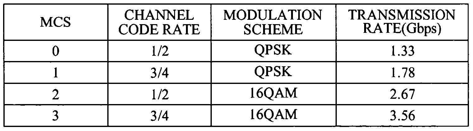
In this instance, the signal symbol may include at least one of a Modulation and Code rate Symbol (MCS) field of a subcarrier, a byte number field, a scrambler seed of the fast wireless communication frame, a cyclic redundancy check (CRC) parity bit field, a tail bit field for initialization of the convolution demodulator.
In this instance, the MCS field may be determined by the following table.
Figure imgf000006_0001
In this instance, the signal symbol may further include a reserved bit of one bit after the MCS field of the subcarrier and a reserved bit of 51 bits after the scrambler seed field of the fast wireless communication frame.
In this instance, the data symbol may consist of 576 samples, and a number of the data symbol may be determined depending on a number of bytes of the transmission data to be transmitted via the fast wireless communication frame. According to an exemplary embodiment of the present invention, there is provided an apparatus for fast wireless communication including: a preamble processing unit performing a preamble process to down-sample a received signal four times, to detect a carrier and a frequency offset, and to synchronize a frame; a demultiplexing unit demultiplexing transmission data included in the received signal into N number of parallel streams (N: positive number greater than 2); N number of demodulation and decoding units connected in parallel for performing OFDM and error correction with respect to each of the N number of parallel streams; and a multiplexing unit multiplexing outputs of the N number of demodulation and decoding units into serial streams.
In this instance, the demultiplexing unit may provide a (4M + l)th (M = 0, 1, 2, ...) OFDM symbol from the received signal to a first demodulation and decoding unit of the N number of demodulation and decoding units, provide a (4M + 2)th OFDM symbol from the received signal to a second demodulation and decoding unit of the N number of demodulation and decoding units, provide a (4M + 3)th OFDM symbol from the received signal to a third demodulation and decoding unit of the N number of demodulation and decoding units, and provides a (4M + 4)th OFDM symbol from the received signal to a fourth demodulation and decoding unit of the N number of demodulation and decoding units.
Advantageous Effects
According to the exemplary embodiment of the present invention, it is possible to increase data quantity to be processed in a single process and to increase internal operational speed of the system by adjusting a number of parallel streams in the fast wireless communication system.
Also, according to the exemplary embodiment of the present invention, it is possible to maintain high speed data transmission with a relatively slow system clock speed when implementing a digital circuit of the fast wireless communication system.
Also, according to the exemplary embodiment of the present invention, it is possible to increase data quantity to be processed in a single process when a higher transmission rate is required in a fast wireless communication system, and to reduce power consumption by reducing a multiplexing rate of a parallel stream when a lower transmission rate is required.
Brief Description of Drawings
FIG. 1 is a block diagram illustrating an apparatus for fast wireless communication according to an exemplary embodiment of the present invention;
FIG. 2 illustrates an example of a configuration of a fast wireless communication frame for fast wireless communication according to an exemplary embodiment of the present invention;
FIG. 3 illustrates an example of a frame configuration of a signal symbol according to an exemplary embodiment of the present invention;
FIG. 4 illustrates an example of a configuration of a scrambler scrambling transmission data of the exemplary embodiments;
FIG. 5 illustrates an example of a configuration of a convolutional encoder performing convolutional encoding of the exemplary embodiments; FIG. 6 illustrates an example of puncturing operations for making a channel code rate from 1/2 to 2/3 of the exemplary embodiments; and
FIG. 7 is a block diagram illustrating a receiver of an apparatus for fast wireless communication according to an exemplary embodiment of the present invention.
Best Mode for Carrying Out the Invention
Hereinafter, exemplary embodiments of the present invention will be described in detail by referring to accompanied drawings according to exemplary embodiments of the present invention. When detailed descriptions related to a well-known related function or configuration are determined to make the spirits of the present invention ambiguous, the detailed descriptions will be omitted herein. Also, terms used throughout the present specification are used to appropriately describe exemplary embodiments of the present invention, and thus may be different depending upon a user and an operator's intention, or practices of application fields of the present invention. Therefore, the terms must be defined based on descriptions made through the present invention.
An apparatus for fast wireless communication described as below performs fast data transmissions using time division multiplex wireless transmission. Also, the apparatus for fast wireless communication described below may be applied to a physical layer of Wireless Personal Area Network (WPAN) operating in a high frequency band.
FIG. 1 is a block diagram illustrating a transmitter of an apparatus for fast wireless communication according to an exemplary embodiment of the proposed invention.
Referring to FIG. 1, the transmitter of the apparatus for fast wireless communication may include a frame configuration unit 101 configuring a frame including transmission data, a demultiplexing unit 103 performing demultiplexing of transmission data included in the frame into N number of parallel streams (N: positive number greater than 2). The transmitter of the apparatus for fast communication may also include N number of coding and modulation units 105, 107, 109 and 111, and a multiplexing unit 121 multiplexing outputs of the N number of coding and modulation units 105, 107, 109 and 111 into serial streams. Here, although FIG. 1 illustrates an example where N is 4, N may vary depending on transmission rates required for the system.
Here, the transmitter of the apparatus for fast wireless communication may additionally include buffers 113, 115, 117 and 119 which are used to temporarily store the outputs from the N number of coding and modulating units 105, 107, 109 and 111. This is for the purpose of multiplexing the outputs from the outputs of the N number of coding and modulating units 105, 107, 109.
Also, the transmitter of the apparatus for fast wireless communication may additionally include a transmission unit 123 for the purpose of converting the serial streams which have been multiplexed by the multiplexing unit 121 into analog signals and for the purpose of transmitting to the receiver. The frame configuration unit 101 may be configured to include a scrambler
(not illustrated) which scrambles the transmission data by scrambling polynomials.
Here, the scrambling is performed to reduce a high amplitude of time domain signals. As an example of scrambling occurring polynomials, the following Equation 1 may be applied. [Equation 1]
G(x) = x7 + x4 + 1
An embodiment of an exemplary scrambler scrambling the transmission data by applied Equation 1 is as illustrated in FIG. 4.
The demultiplexing unit 103 performs demultiplexing of the scrambled inputted streams into four parallel streams. Here, the demultiplexing unit 103 can control the number of parallel streams depending on transmission rate requested from the system.
As an example, in case that the transmission rate requested from the system is low, inputted streams are multiplexed into two parallel streams, and in case that the transmission rate requested from the system is high, the inputted streams may be multiplexed into four parallel streams. Here, the transmission rate requested from the system may be provided by a system controlling unit (not illustrated) to the demultiplexing unit 103.
Each of the N number of coding and modulating units 105, 107, 109 and 111 illustrated in FIG. 1 may include a convolutional encoder performing error correction coding with respect to an inputted stream according to a convolution polynomial, an interleaver interleaving the coded inputted stream, an inverse Fast Fourier Transformer (IFFT) performing inverse Fast Fourier Transform (IFFT) to transform the interleaved signal, outputted from the interleaver, into a time domain signal, and a cyclic prefix (CP) insertion unit inserting a cyclic prefix into the time domain signal.
Here, for the polynomial for convolution encoding, g0 = 1338 and gi = 171g may be used. An exemplary embodiment of the convolutional encoder using the polynomials of go = 133g and gj = 17I8 is as illustrated in FIG. 5.
Alternatively, in case that the polynomials of go = 1338 and gi = 17I8 are applied, a channel coding rate is 1/2. An example of a puncturing process to increase the channel coding rate from 1/2 to 2/3 is as illustrated in FIG. 6. The convolutional encoder may initialize a status using six 0 (zero) bits inserted in the inputted streams. Consequently, the frame configuration unit 101 may insert six 0 (zero) bits into the transmission data for the purpose of initialization of the convolutional encoder. Here, the frame configuration unit 101 is capable of inserting a total of twenty-four 0 (zero) bits into the transmission data for the initializations of each of four convolutional encoders.
As described above, the transmitter of the apparatus for fast communication, by using the fixed system clock speed, may parallelize the scrambled transmission data, and perform the error correction coding and orthogonal frequency division multiplexing (OFDM) via independent routing of the each parallel streams in order to maintain high speed data transmission.
FIG. 2 illustrates an example of a configuration of a fast wireless communication frame for fast wireless communication according to an exemplary embodiment of the present invention.
Referring to FIGS. 1 and 2, the fast wireless communication frame for fast wireless communication may be generated by the frame configuration unit 101.
This represents that the frame configuration unit 101 is capable of configuring a short symbol giving a notification about a start of the fast wireless communication frame, a long symbol estimating a channel which transmits the fast wireless communication frame, a signal symbol demodulating the fast wireless communication frame, and a data symbol of transmission data to be transmitted via the fast wireless communication frame. Here, the short symbol, long symbol, and signal symbols are not multiplexed into parallel streams, and error correction coding and OFDM may be performed on each of the N number of coding and modulating units 105, 107, 109, and 111 by any one of the N number of coding and modulation units 105, 107, 109 and 111.
Consequently, the frame structure for fast wireless communication includes a short symbol field 201 giving notification about the start of the fast wireless communication frame, a long symbol field 203 for channel estimation, the signal field 205 having information for modulation, and a data field 207 having transmission data.
The short symbol may be configured by iterating a signal stream having a 128- sample length 12 times, and the 12th iterated signal stream may have a phase difference of 180 degrees from a 11th iterated signal stream.
Also, the short symbol may generate 512 complex numbers using a value corresponding to a subcarrier index shown in the table below, and may generate the 512 complex numbers by performing IFFT.
In this instance, Table 1 shows values which are obtained inputs of a subcarrier index from -256 to 255 of a point IFFT. Here, other indexes are 0 except the indexes shown in Table 1, the real parts and imaginary parts of the complex numbers are identical and a direct current (DC) subcarrier index is 0. The short symbol generated using Table 1 may have a structure that a signal stream of 128-sample length is iterated four times.
[Table 1]
Figure imgf000012_0002
Also, the subcarrier for transmitting the short symbol is generated from a permutation having a maximum length of 31, and the short symbol may be down- sampled so as to have identical power to the subcarrier.
Alternatively, since single data occupies an identical location from among each of the four subcarriers, the iteration property of time domain permutation is maintained even in the case of the down-sampling of the short symbol.
Also, when short symbol is down-sampled to have same power as the subcarriers as above, it is possible to perform a preamble process without using a low pass filter at the receiver.
The IFFT calculation for generating of the short symbol may be performed by the following Equation 2. [Equation 2]
rSHORT V ) —
Figure imgf000012_0001
£=-256
In Equation 2, Sk is a frequency domain value listed in Table 1, and Δf indicates a spatial distance of 3.9 MHz between subcarriers. 12 signal streams which are comprised of a short symbol may be obtained by iterating the results of Equation 2 three times. However, a last 12th signal stream is opposite to a phase of an 11th signal stream.
The long symbol may be configured to have a sample length of 576. Here, the long symbol may be generated by IFFT calculation with respect to the following frequency domain permutations.
{ L-256, L-255 L255} = {
0, 0, 0, 0, 0, 0, 0, 0, 0, 0, 0, 0, 0, 0, 0, 0, 0, 0, 0, 0, 0, 0, 0, 0, 0, 0, 0, 0, 0, 0, 0, 0, 0, 0, 0, 0, 0, 0,
0, 0, 0, 0, 0, 0, 0, 0, 0, 0, 0, 0, 0, 0, 0, 0, 0, 0, 0, 0, 0,-1, 1,-1,-1, 1, 1, 1, 1,-1, 1,-1, 1,-1,-1, 1,-1, 1,-1,-1,-1,-1,-1,-1, 1,-1, 1,-1, 1,-1, 1,-1, 1, 1, 1, 1, 1,-1, 1,-1, 1, 1,-1, 1,-1,-1,-1,-1,-1, 1, 1,-1, 1, 1, 1,-1, 1, 1,-1, 1, 1,-1, 1,-1,1, 1,-1,-1,-1,-1,-1, 1,-1, 1, 1, 1,-1, 1, 1, 1, 1, 1,-1,-1,-1, 1, 1, 1, 1,-1,-1, 1, 1,-1, 1,-1,-1, 1, 1,-1, 1,-1, 1, 1, 1,-1,-1,-1, 1, 1,-1, 1,-1,-1,-1, 1,-1, 1, 1, 1, 1, 1, 1, 1,-1, 1,-1,-1, 1,-1, 1, 1,-1,-1, -1, 1,-1, 1,-1,-1, 1, 1,-1,-1,-1, 1, 1,-1,-1,-1,-1,-1,-1,-1, 1, 1,-1,-1, 1, 1,-1,-1, 1,-1, 1,-1,1, 1,-1,-1, 1,-1,-1, 1, 1, 1, 1, 1, 1,-1, 1, 1,-1, 1,-1,-1, 1,-1,-1, 1,-1,-1, 1, 1,-1, 1, 1, 0, 0, 0, 1, 1, 1,-1,-1,-1, 1,-1,-1, 1,-1, 1,-1, 1,-1,-1,-1, 1, 1,-1, 1, 1,-1,-1, 1, 1, 1, 1, 1,-1, -1, 1, 1, 1, 1,-1,-1,-1, 1,-1, 1, 1,-1, 1, 1, 1,-1,-1, 1,-1, 1,-1,-1, 1,-1,-1,-1,-1,-1, 1,-1,-1, 1, 1,-1,-1, 1, 1, 1,-1, 1,-1,-1,-1, 1,
1, 1, 1, 1,-1, 1, 1, 1, 1,-1,-1,-1,-1,-1, 1, 1, 1, 1, 1, 1, 1, 1, 1,-1,-1,-1,-1, 1, 1, 1, 1,-1, 1, 1, 1,-1,-1,-1,-1, 1,-1, 1, 1,-1,-1, 1, 1,-1, 1, 1,-1, 1, 1, 1, 1,-1, 1,-1,-1,-1,-1, 1, 1, 1,-1,-1, 1, 1,-1,-1,-1,-1, 1,-1,-1, 1,-1,-1,-1, 1,-1, 1,-1, 1, 1, 1,-1, 1,-1, 1, 1, 1, 1,-1,-1, 1,-1,-1, 1,-1, 1, 1, 1,-1,-1, 1, 1, 1,-1,-1,-1,-1,-1,-1, 1, 1, 1,-1, 1, 1, 1, 0, 0, 0, 0, 0, 0, 0, 0, 0, 0, 0, 0, 0, 0, 0, 0, 0, 0, 0, 0, 0, 0, 0, 0, 0, 0, 0, 0, 0, 0, 0, 0, 0, 0, 0, 0, 0, 0, 0, 0, 0, 0, 0, 0, 0, 0, 0, 0, 0, 0, 0, 0, 0, 0, 0, 0, 0, 0}.
The IFFT calculation for generation of the long symbol may be performed with the following Equation 3. [Equation 3]
rLONG (t)
Figure imgf000013_0001
Lk -
£=-256
In Equation 3, Lk is a frequency domain permutation value, where Δf is a subcarrier spatial distance of 3.5MHz, and Tcp is 32 nsec of a cyclic prefix (CP).
An example of a frame configuration of the above signal symbols is as illustrated in FIG. 3.
Referring to FIG. 3, the signal symbol configuration may include at least one Modulation and Code rate Symbol (MCS) field 301 of a subcarrier, a byte number field 305, a scrambler seed field 307 of the fast wireless communication frame, a cyclic redundancy check (CRC) parity bit field 311, and a tail bit field 313 for initialization of the convolution demodulator.
The MCS field 301 of the subcarriers may include information regarding the MCS of the subcarriers supported by the apparatus for fast communication according to the exemplary embodiment of the present invention.
The following Table 2 illustrates an example of the MCS for the subcarriers for fast wireless communication.
[Table 2]
Figure imgf000014_0001
Aside from the MSC described in Table 2, various other MCSs may be applied.
The signal symbol may additionally include a reserved bit 303 of one bit after the MCS field 301 of the subcarrier and reserved bits 309 of 51 bits after the scrambler seed value field 307 of the fast wireless communication frame.
Here, the reserved bit 303, and reserved bits 309 may be padded with a value of 0.
A byte number field 305 may have length information of the transmission data transmitted in a byte unit in a data symbol area of the fast wireless communication frame.
A CRC code being inserted in the CRC parity field 311 is used to detect a receiving error rate at the receiver.
The following Equation 4 represents an example of CRC generation polynomials for CRC code generation. [Equation 4] xn + xn +x3 +x2 + x + \ The tail field 313 is padded with six 0s. A CRC error detector (not illustrated) may be aware of termination of decoding operation through six Os padding the tail field 313. On the other hand, the above symbol signal may be scrambled with a scrambler which is established as an initial value of 3F of 16 antilogarithm. A subsequently scrambled signal symbol is encoded via 1/2 error correction encoder, and, before the error corrected 192 bits are interleaved, they are repeated four times to generate data of 768 bits. Data of 768 bits may be modulated by 386 subcarriers using Quadrature phase-shift keying (QPSK). The modulation of a signal symbol may be performed by the frame configuration unit 101 and the coding and modulation units 105 of FIG. 1.
As described above, the signal symbol and data symbol are scrambled prior to the error correction coding. An initial value of a shift register of the scrambler for scrambling of a signal symbol may be established as 3Fs of 16 bits, and an initial value of a shift register of a scrambler for scrambling of data symbol may be randomly established.
Here, the initial value of the shift register for decoding of data symbols is inserted in the scrambler seed field 307 of the signal symbol.
The above data symbols consists of 576 samples, and a number of the data symbols may be adjusted according to a number of bytes of transmitted data desired to be transmitted via the fast wireless communication frame.
The apparatus for fast communication according to an exemplary embodiment of the proposed invention may utilize OFDM modulation technology to transmit data via wireless signals of a millimeter-wave band. Here, examples of OFDM parameters applied on the apparatus for fast communication is illustrated in Table 3 as follows: [Table 3]
Figure imgf000016_0001
FIG. 7 is a block diagram of a receiver of an apparatus for fast communication according to an exemplary embodiment of the proposed invention.
Referring to FIG. 7, the receiver of the apparatus for fast communication may include a receiving unit 701 converting a received signal into a digital signal and a preamble processing unit 725 performing a preamble process to down-sample the received signal four times, to detect a carrier and a frequency offset, and to synchronize a frame. The receiver of the apparatus for fast communication may also include a demultiplexing unit 703 demultiplexing transmission data included in the received signal into N number of parallel streams (N: positive number greater than 2), N number of demodulation and decoding units 713, 715, 717 and 719 connected in parallel for performing OFDM and error correction with respect to each of the N number of parallel streams, and a multiplexing unit 721 multiplexing outputs of the N number of demodulation and decoding units 713, 715, 717 and 719 into serial streams. Here, although FIG. 7 illustrates an example where N is 4, N may vary depending on a transmission rate required for the system.
Here, the receiver of the apparatus for fast communication may further include buffers 705, 707, 709 and 711 which are used to temporarily store outputs from the demultiplexing unit 703. Also, the receiver of the apparatus for fast communication may further include a descrambler 723 to descramble serial streams which are multiplexed via the multiplexing unit 721. The preamble processing unit 725, for the purpose of preamble process of the received signals, performs down-sampling of the received signals using a factor of 4. Here, the preamble processing unit 725 may process a preamble process for a short symbol included in the received signal without low pass filtering. Referring to FIG. 7, a configuration of the preamble processing unit 725 may include a down sampling unit performing down sampling with respect to digital signals from Analog Digital Convert (ADC) conversion using a factor of 4, a carrier detecting unit detecting a frequency size of a carrier from preamble signals (short and long symbols), a Carrier Frequency Offset (CFO) estimation unit estimating CFOs of carrier waves, and a symbol synchronizing unit synchronizing symbols using general synchronization algorithms.
The preamble processing unit 725 may provide information regarding a symbol boundary and symbol synchronization to the demultiplexing unit 703, and the demultiplexing unit 703 may perform demultiplexing of digital signal being inputted based on the symbol boundary information.
As an example, the demultiplexing unit 703 provides a (4M + l)th (M = 0, 1, 2, ...) OFDM symbol from the received signal to a first demodulation and the decoding unit 713 of the N number of demodulation and decoding units, provides a (4M + 2)' OFDM symbol from the received signal to the second demodulation and decoding unit 715 of the N number of demodulation and decoding units, provides a (4M + 3)th OFDM symbol from the received signal to the third demodulation and decoding unit 717 of the N number of demodulation and decoding units, and provides a (4M + 4)th OFDM symbol from the received signal to the fourth demodulation and decoding unit 719 of the N number of demodulation and decoding units. As illustrated in FIG. 7, each of the demodulation and decoding units 713, 715,
717 and 719 may be configured to include a CFO correct correcting a frequency offsets of a carrier in a received signal, a fast Fourier transformer (FFT) converting a time domain signal to a frequency domain signal, a de-interleaver de-interleaving the signal converted to the frequency domain, and a convolution decoding unit performing error correction coding the de-interleaved signal.
The foregoing descriptions of specific embodiments of the present invention have been presented for purposes of illustration and description. They are not intended to be exhaustive or to limit the invention to the precise forms disclosed, and obviously many modifications and variations are possible in light of the above teaching. Therefore, it is intended that the scope of the invention be defined by the claims appended thereto and their equivalents.
Although a few embodiments of the present invention have been shown and described, the present invention is not limited to the described embodiments. Instead, it would be appreciated by those skilled in the art that changes may be made to these embodiments without departing from the principles and spirit of the invention, the scope of which is defined by the claims and their equivalents.

Claims

1. An apparatus for fast wireless communication, the apparatus comprising: a frame configuration unit configuring a frame including transmission data; a demultiplexing unit demultiplexing the transmission data included in the frame into N number of parallel streams (N: positive number greater than 2);
N number of coding and modulation units connected in parallel to perform error correction coding and orthogonal frequency division multiplexing (OFDM) with respect to each of the N number of parallel streams; and a multiplexing unit multiplexing outputs of the N number of coding and modulation units into serial streams.
2. The apparatus of claim 1, wherein the frame configuration unit scrambles the transmission data according to a scrambling polynomial to provide the scrambled transmission data to the demultiplexing unit.
3. The apparatus of claim 1, wherein the each of the N number of coding and modulation units comprises: a convolutional encoder performing error correction coding with respect to an inputted stream according to a convolution polynomial; an interleaver interleaving the coded inputted stream; an inverse Fast Fourier Transformer performing inverse Fast Fourier Transform (IFFT) with respect to the interleaved signal, outputted from the interleaver, into a time domain signal; and a cyclic prefix (CP) insertion unit inserting a cyclic prefix into the time domain signal.
4. The apparatus of claim 1 , wherein the frame comprises a short symbol giving notification about a start of a frame, a long symbol for channel estimation, a signal symbol having information for demodulation, and a data symbol having a transmission symbol.
5. The apparatus of claim 4, wherein the short, long, and signal symbol is performed error correction coding and OFDM by any one of the N number of coding and modulation units.
6. The apparatus of claim 1, wherein N corresponds to 4.
7. A method for configuring a frame for fast wireless communication, the method comprising: configuring a short symbol giving notification about a start of a fast wireless communication frame; configuring a long symbol estimating a channel which transmits the fast wireless communication frame; configuring a signal symbol demodulating the fast wireless communication frame; and configuring a data symbol of transmission data to be transmitted via the fast wireless communication frame.
8. The method of claim 7, wherein the short symbol is configured by iterating a signal stream having a 128-sample length 12 times, and the 12th iterated signal stream has a phase difference of 180 degrees from a 11th iterated signal stream.
9. The method of claim 7, wherein the short symbol generates 512 complex numbers using a value corresponding to a subcarrier index shown in the following table, and generates the 512 complex numbers by performing IFFT.
Figure imgf000021_0001
(where the real parts and imaginary parts of the 512 complex numbers are identical)
10. The method of claim 9, wherein the subcarrier for transmitting the short symbol is generated from a permutation having a maximum length of 31.
11. The method of claim 7, wherein the long symbol has a 576-sample length.
12. The method of claim 7, wherein the long symbol is generated by performing IFFT with respect to the following permutation in a frequency domain,
{ L-256, L-255, ..., L255} = { 0, 0, 0, 0, 0, 0, 0, 0, 0, 0, 0, 0, 0, 0, 0, 0, 0, 0, 0, 0, 0, 0, 0, 0, 0, 0, 0, 0, 0, 0, 0, 0, 0, 0, 0, 0, 0, 0,
0, 0, 0, 0, 0, 0, 0, 0, 0, 0, 0, 0, 0, 0, 0, 0, 0, 0, 0, 0, 0,-1, 1,-1,-1, 1, 1, 1, 1,-1, 1,-1, 1,-1,-1, 1,-1, 1,-1,-1,-1,-1,-1,-1, 1,-1, 1,-1, 1,-1, 1,-1, 1, 1, 1, 1, 1,-1, 1,-1, 1, 1,-1, 1,-1,-1,-1,-1,-1, 1, 1,-1, 1, 1, 1,-1, 1, 1,-1, 1, 1,-1, 1,-1,1, 1,-1,-1,-1,-1,-1, 1,-1, 1, 1, 1,-1, 1, 1, 1, 1, 1,-1,-1,-1, 1, 1, 1, 1,-1,-1, 1, 1,-1, 1,-1,-1, 1, 1,-1, 1,-1, 1, 1, 1,-1,-1,-1, 1, 1,-1, 1,-1,-1,-1, 1,-1, 1, 1, 1, 1, 1, 1, 1,-1, 1,-1,-1, 1,-1, 1, 1,-1,-1, -1, 1,-1, 1,-1,-1, 1, 1,-1,-1,-1, 1, 1,-1,-1,-1,-1,-1,-1,-1, 1, 1,-1,-1, 1, 1,-1,-1, 1,-1, 1,-1,1, 1,-1,-1, 1,-1,-1, 1, 1, 1, 1, 1, 1,-1, 1, 1,-1, 1,-1,-1, 1,-1,-1, 1,-1,-1, 1, 1,-1, 1, 1, 0, 0, 0, 1, 1, 1,-1,-1,-1, 1,-1,-1, 1,-1, 1,-1, 1,-1,-1,-1, 1, 1,-1, 1, 1,-1,-1, 1, 1, 1, 1, 1,-1, -1, 1, 1, 1, 1,-1,-1,-1, 1,-1, 1, 1,-1, 1, 1, 1,-1,-1, 1,-1, 1,-1,-1, 1,-1,-1,-1,-1,-1, 1,-1,-1, 1, 1,-1,-1, 1, 1, 1,-1, 1,-1,-1,-1, 1,
1, 1, 1, 1,-1, 1, 1, 1, 1,-1,-1,-1,-1,-1, 1, 1, 1, 1, 1, 1, 1, 1, 1,-1,-1,-1,-1, 1, 1, 1, 1,-1, 1, 1, 1,-1,-1,-1,-1, 1,-1, 1, 1,-1,-1, 1, 1,-1, 1, 1,-1, 1, 1, 1, 1,-1, 1,-1,-1,-1,-1, 1, 1, 1,-1,-1, 1, 1,-1,-1,-1,-1, 1,-1,-1, 1,-1,-1,-1, 1,-1, 1,-1, 1, 1, 1,-1, 1,-1, 1, 1, 1, 1,-1,-1, 1,-1,-1, 1,-1, 1, 1, 1,-1,-1, 1, 1, 1,-1,-1,-1,-1,-1,-1, 1, 1, 1,-1, 1, 1, 1, 0, 0, 0, 0, 0, 0, 0, 0, 0, 0, 0, 0, 0, 0, 0, 0, 0, 0, 0, 0, 0, 0, 0, 0, 0, 0, 0, 0, 0, 0, 0, 0, 0, 0, 0, 0, 0, 0, 0, 0, 0, 0, 0, 0, 0, 0, 0, 0, 0, 0, 0, 0, 0, 0, 0, 0, 0, 0}.
13. The method of claim 7, wherein the signal symbol comprises at least one of Modulation and Code rate Symbol (MCS) field of a subcarrier, a byte number field, a scrambler seed field of the fast wireless communication frame, a cyclic redundancy check (CRC) parity bit field, and a tail bit field for initialization of the convolution demodulator.
14. The method of claim 13, wherein the MCS field is determined by the following table,
Figure imgf000022_0001
15. The method of claim 13, wherein the signal symbol further comprises a reserved bit of one bit after the MCS field and a reserved bit of 51 bits after the scrambler seed field of the fast wireless communication frame.
16. The method of claim 8, wherein the data symbol consists of 576 samples, and a number of the data symbol is determined depending on a number of bytes of the transmission data to be transmitted via the fast wireless communication frame.
17. An apparatus for fast wireless communication, the apparatus comprising: a preamble processing unit performing a preamble process to down-sample a received signal four times, to detect a subcarrier and a frequency offset, and to synchronize a frame; a demultiplexing unit demultiplexing transmission data included in the received signal into N number of parallel streams (N: positive number greater than 2);
N number of demodulation and decoding units connected in parallel for performing OFDM and error correction with respect to each of the N number of parallel streams; and a multiplexing unit multiplexing outputs of the N number of demodulation and decoding units into serial streams.
18. The apparatus of claim 17, wherein the demultiplexing unit provides a (4M + 1 )th (M = 0, 1 , 2, ... ) OFDM symbol from the received signal to a first demodulation and decoding unit of the N number of demodulation and decoding units, provides a (4M + 2)th OFDM symbol from the received signal to a second demodulation and decoding unit of the N number of demodulation and decoding units, provides a (4M + 3)th OFDM symbol from the received signal to a third demodulation and decoding unit of the N number of demodulation and decoding units, and provides a (4M + 4)th OFDM symbol from the received signal to a fourth demodulation and decoding unit of the N number of demodulation and decoding units.
19. The apparatus of claim 17, wherein the frame of the received signal comprises a short symbol giving a notification about a start of a frame, a long symbol for channel estimation, a signal symbol having information for demodulation, and a data symbol having transmission symbol.
PCT/KR2008/005179 2007-09-04 2008-09-03 Frame structure for fast wireless communication system and apparatus for fast wireless communication using the frame WO2009031808A2 (en)

Priority Applications (2)

Application Number Priority Date Filing Date Title
US12/676,537 US8605802B2 (en) 2007-09-04 2008-09-03 Frame structure for fast wireless communication system and apparatus for fast wireless communication using the frame
JP2010523945A JP2010538568A (en) 2007-09-04 2008-09-03 FRAME CONFIGURATION METHOD FOR HIGH SPEED WIRELESS COMMUNICATION AND HIGH SPEED WIRELESS COMMUNICATION DEVICE USING THE SAME

Applications Claiming Priority (4)

Application Number Priority Date Filing Date Title
KR20070089572 2007-09-04
KR10-2007-0089572 2007-09-04
KR10-2008-0082852 2008-08-25
KR1020080082852A KR20090024623A (en) 2007-09-04 2008-08-25 Frame structure for fast wireless communication system and apparatus for fast wireless communication using the frame

Publications (2)

Publication Number Publication Date
WO2009031808A2 true WO2009031808A2 (en) 2009-03-12
WO2009031808A3 WO2009031808A3 (en) 2009-04-30

Family

ID=40429534

Family Applications (1)

Application Number Title Priority Date Filing Date
PCT/KR2008/005179 WO2009031808A2 (en) 2007-09-04 2008-09-03 Frame structure for fast wireless communication system and apparatus for fast wireless communication using the frame

Country Status (1)

Country Link
WO (1) WO2009031808A2 (en)

Cited By (1)

* Cited by examiner, † Cited by third party
Publication number Priority date Publication date Assignee Title
JP2014225889A (en) * 2009-03-27 2014-12-04 クゥアルコム・インコーポレイテッドQualcomm Incorporated System and method of transmitting and receiving data frames

Citations (3)

* Cited by examiner, † Cited by third party
Publication number Priority date Publication date Assignee Title
KR20040000517A (en) * 2002-03-11 2004-01-07 주식회사 내그림 A multipurpose printer
KR20060006661A (en) * 2004-07-16 2006-01-19 삼성전자주식회사 Apparatus and method for searching modem channel on cable based digital broadcasting
KR20070008823A (en) * 2005-07-12 2007-01-18 엘지전자 주식회사 Trim kit structure of out-door for refrigerator

Patent Citations (3)

* Cited by examiner, † Cited by third party
Publication number Priority date Publication date Assignee Title
KR20040000517A (en) * 2002-03-11 2004-01-07 주식회사 내그림 A multipurpose printer
KR20060006661A (en) * 2004-07-16 2006-01-19 삼성전자주식회사 Apparatus and method for searching modem channel on cable based digital broadcasting
KR20070008823A (en) * 2005-07-12 2007-01-18 엘지전자 주식회사 Trim kit structure of out-door for refrigerator

Non-Patent Citations (1)

* Cited by examiner, † Cited by third party
Title
'IEEE International Conference on Communications, 18-22 June 1995', article CHIH-LIN I ET AL.: 'Multi-Code CDMA Wireless Personal Communications Networks', pages 1060 - 1064 *

Cited By (1)

* Cited by examiner, † Cited by third party
Publication number Priority date Publication date Assignee Title
JP2014225889A (en) * 2009-03-27 2014-12-04 クゥアルコム・インコーポレイテッドQualcomm Incorporated System and method of transmitting and receiving data frames

Also Published As

Publication number Publication date
WO2009031808A3 (en) 2009-04-30

Similar Documents

Publication Publication Date Title
US8605802B2 (en) Frame structure for fast wireless communication system and apparatus for fast wireless communication using the frame
WO2008087603A2 (en) Method and system of single carrier block transmission with parallel encoding and decoding
WO2011088734A1 (en) Offset modulation orthogonal frequency division multiplexing (ofdm) and multi-access transmission method with cyclic prefix (cp)
EP1829312A1 (en) Apparatus for transmitting and receiving data to provide high-speed data comunication and method thereof
US9537698B2 (en) Apparatus for transmitting broadcast signals, apparatus for receiving broadcast signals, method for transmitting broadcast signals and method for receiving broadcast signals
US20200252121A1 (en) Techniques for expanding communication range between wireless devices
JP6718320B2 (en) Single-carrier transmission device and reception device, and transmission method, reception method, and transmission frame configuration method
WO2008149082A1 (en) Apparatus and method for coded orthogonal frequency- division multiplexing
EP2491692A1 (en) A communications system utilizing orthogonal linear frequency modulated waveforms
WO2005041441A1 (en) Apparatus and method for cyclic delay diversity
KR101544476B1 (en) Ofdm signal transmitter and ofdm signal receiver
KR100375824B1 (en) OFDM Modem Method Suitable For Wireless LAN System And Supporting Variable Data Rate By Allocating Variable Bits To OFDM Subcarrier
JP6317696B2 (en) Communication apparatus and communication system
JPWO2008149510A1 (en) Transmitting apparatus, multicarrier transmission method, and receiving apparatus
WO2009031808A2 (en) Frame structure for fast wireless communication system and apparatus for fast wireless communication using the frame
KR20040028230A (en) COFDM transmission system add pilot signal in frequence domain and a method proessing OFDM signal thereof
Thenmozhi et al. Suitability of coded orthogonal frequency division multiplexing (cofdm) for multimedia data transmission in wireless telemedicine applications
KR100884407B1 (en) TDS-OFDM transmission system having 3780-????? ????/??? procseeor and structure of 3780- ?? procseeor
KR20040029824A (en) TDS-OFDM transmission system having 3600-point IDFT procseeor and a method proessing OFDM signal thereof
JP5912025B2 (en) Communication apparatus and communication system
KR20040028226A (en) TDS-OFDM transmission system add pilot signal in frequence domain and a method proessing OFDM signal thereof
EP2153604A1 (en) Ofdm signal transmission apparatus and method
JP3836664B2 (en) Communication apparatus and communication method
CN110830148A (en) Uplink common control channel configuration method for non-aligned multi-user transmission
Ryoo Performance Evaluation of Improved OFDM-based MTCM in Mobile Communication Systems

Legal Events

Date Code Title Description
121 Ep: the epo has been informed by wipo that ep was designated in this application

Ref document number: 08793664

Country of ref document: EP

Kind code of ref document: A2

ENP Entry into the national phase

Ref document number: 2010523945

Country of ref document: JP

Kind code of ref document: A

WWE Wipo information: entry into national phase

Ref document number: 12676537

Country of ref document: US

NENP Non-entry into the national phase

Ref country code: DE

122 Ep: pct application non-entry in european phase

Ref document number: 08793664

Country of ref document: EP

Kind code of ref document: A2