WO2009031806A2 - Multi-functional optical film - Google Patents
Multi-functional optical film Download PDFInfo
- Publication number
- WO2009031806A2 WO2009031806A2 PCT/KR2008/005174 KR2008005174W WO2009031806A2 WO 2009031806 A2 WO2009031806 A2 WO 2009031806A2 KR 2008005174 W KR2008005174 W KR 2008005174W WO 2009031806 A2 WO2009031806 A2 WO 2009031806A2
- Authority
- WO
- WIPO (PCT)
- Prior art keywords
- light
- optical film
- multifunctional optical
- film
- layer
- Prior art date
- Legal status (The legal status is an assumption and is not a legal conclusion. Google has not performed a legal analysis and makes no representation as to the accuracy of the status listed.)
- Ceased
Links
Classifications
-
- G—PHYSICS
- G02—OPTICS
- G02F—OPTICAL DEVICES OR ARRANGEMENTS FOR THE CONTROL OF LIGHT BY MODIFICATION OF THE OPTICAL PROPERTIES OF THE MEDIA OF THE ELEMENTS INVOLVED THEREIN; NON-LINEAR OPTICS; FREQUENCY-CHANGING OF LIGHT; OPTICAL LOGIC ELEMENTS; OPTICAL ANALOGUE/DIGITAL CONVERTERS
- G02F1/00—Devices or arrangements for the control of the intensity, colour, phase, polarisation or direction of light arriving from an independent light source, e.g. switching, gating or modulating; Non-linear optics
- G02F1/01—Devices or arrangements for the control of the intensity, colour, phase, polarisation or direction of light arriving from an independent light source, e.g. switching, gating or modulating; Non-linear optics for the control of the intensity, phase, polarisation or colour
- G02F1/13—Devices or arrangements for the control of the intensity, colour, phase, polarisation or direction of light arriving from an independent light source, e.g. switching, gating or modulating; Non-linear optics for the control of the intensity, phase, polarisation or colour based on liquid crystals, e.g. single liquid crystal display cells
- G02F1/133—Constructional arrangements; Operation of liquid crystal cells; Circuit arrangements
- G02F1/1333—Constructional arrangements; Manufacturing methods
- G02F1/1335—Structural association of cells with optical devices, e.g. polarisers or reflectors
- G02F1/1336—Illuminating devices
- G02F1/133615—Edge-illuminating devices, i.e. illuminating from the side
-
- G—PHYSICS
- G02—OPTICS
- G02B—OPTICAL ELEMENTS, SYSTEMS OR APPARATUS
- G02B5/00—Optical elements other than lenses
- G02B5/02—Diffusing elements; Afocal elements
-
- G—PHYSICS
- G02—OPTICS
- G02B—OPTICAL ELEMENTS, SYSTEMS OR APPARATUS
- G02B5/00—Optical elements other than lenses
- G02B5/04—Prisms
-
- G—PHYSICS
- G02—OPTICS
- G02F—OPTICAL DEVICES OR ARRANGEMENTS FOR THE CONTROL OF LIGHT BY MODIFICATION OF THE OPTICAL PROPERTIES OF THE MEDIA OF THE ELEMENTS INVOLVED THEREIN; NON-LINEAR OPTICS; FREQUENCY-CHANGING OF LIGHT; OPTICAL LOGIC ELEMENTS; OPTICAL ANALOGUE/DIGITAL CONVERTERS
- G02F1/00—Devices or arrangements for the control of the intensity, colour, phase, polarisation or direction of light arriving from an independent light source, e.g. switching, gating or modulating; Non-linear optics
- G02F1/01—Devices or arrangements for the control of the intensity, colour, phase, polarisation or direction of light arriving from an independent light source, e.g. switching, gating or modulating; Non-linear optics for the control of the intensity, phase, polarisation or colour
- G02F1/13—Devices or arrangements for the control of the intensity, colour, phase, polarisation or direction of light arriving from an independent light source, e.g. switching, gating or modulating; Non-linear optics for the control of the intensity, phase, polarisation or colour based on liquid crystals, e.g. single liquid crystal display cells
- G02F1/133—Constructional arrangements; Operation of liquid crystal cells; Circuit arrangements
- G02F1/1333—Constructional arrangements; Manufacturing methods
- G02F1/1335—Structural association of cells with optical devices, e.g. polarisers or reflectors
-
- G—PHYSICS
- G02—OPTICS
- G02F—OPTICAL DEVICES OR ARRANGEMENTS FOR THE CONTROL OF LIGHT BY MODIFICATION OF THE OPTICAL PROPERTIES OF THE MEDIA OF THE ELEMENTS INVOLVED THEREIN; NON-LINEAR OPTICS; FREQUENCY-CHANGING OF LIGHT; OPTICAL LOGIC ELEMENTS; OPTICAL ANALOGUE/DIGITAL CONVERTERS
- G02F1/00—Devices or arrangements for the control of the intensity, colour, phase, polarisation or direction of light arriving from an independent light source, e.g. switching, gating or modulating; Non-linear optics
- G02F1/01—Devices or arrangements for the control of the intensity, colour, phase, polarisation or direction of light arriving from an independent light source, e.g. switching, gating or modulating; Non-linear optics for the control of the intensity, phase, polarisation or colour
- G02F1/13—Devices or arrangements for the control of the intensity, colour, phase, polarisation or direction of light arriving from an independent light source, e.g. switching, gating or modulating; Non-linear optics for the control of the intensity, phase, polarisation or colour based on liquid crystals, e.g. single liquid crystal display cells
- G02F1/133—Constructional arrangements; Operation of liquid crystal cells; Circuit arrangements
- G02F1/1333—Constructional arrangements; Manufacturing methods
- G02F1/1335—Structural association of cells with optical devices, e.g. polarisers or reflectors
- G02F1/1336—Illuminating devices
- G02F1/133602—Direct backlight
- G02F1/133606—Direct backlight including a specially adapted diffusing, scattering or light controlling members
-
- G—PHYSICS
- G02—OPTICS
- G02F—OPTICAL DEVICES OR ARRANGEMENTS FOR THE CONTROL OF LIGHT BY MODIFICATION OF THE OPTICAL PROPERTIES OF THE MEDIA OF THE ELEMENTS INVOLVED THEREIN; NON-LINEAR OPTICS; FREQUENCY-CHANGING OF LIGHT; OPTICAL LOGIC ELEMENTS; OPTICAL ANALOGUE/DIGITAL CONVERTERS
- G02F1/00—Devices or arrangements for the control of the intensity, colour, phase, polarisation or direction of light arriving from an independent light source, e.g. switching, gating or modulating; Non-linear optics
- G02F1/01—Devices or arrangements for the control of the intensity, colour, phase, polarisation or direction of light arriving from an independent light source, e.g. switching, gating or modulating; Non-linear optics for the control of the intensity, phase, polarisation or colour
- G02F1/13—Devices or arrangements for the control of the intensity, colour, phase, polarisation or direction of light arriving from an independent light source, e.g. switching, gating or modulating; Non-linear optics for the control of the intensity, phase, polarisation or colour based on liquid crystals, e.g. single liquid crystal display cells
- G02F1/133—Constructional arrangements; Operation of liquid crystal cells; Circuit arrangements
- G02F1/1333—Constructional arrangements; Manufacturing methods
- G02F1/1335—Structural association of cells with optical devices, e.g. polarisers or reflectors
- G02F1/1336—Illuminating devices
- G02F1/133602—Direct backlight
- G02F1/133606—Direct backlight including a specially adapted diffusing, scattering or light controlling members
- G02F1/133607—Direct backlight including a specially adapted diffusing, scattering or light controlling members the light controlling member including light directing or refracting elements, e.g. prisms or lenses
Definitions
- the present invention relates to a multifunctional optical film for use in liquid crystal displays.
- LCDs which have already been applied in fields such as notebook computers, monitors for desktop computers, and portable personal communication devices (PDAs and mobile phones), are being manufactured in larger sizes, and thus, it is possible to apply LCDs to large-sized TVs, such as HD
- LCDs are receiving attention as novel displays able to substitute for CRTs, which used to be synonymous for displays.
- the LCD serving as a device for adjusting light transmittance using the electrical properties of liquid crystal material, emits light from a light source lamp mounted to the back surface thereof, and the light thus emitted is passed through various functional prism films or sheets to thus cause light to be uniform and directional, after which such controlled light is also passed through a color filter, thereby realizing red, green, and blue (R, G, B) colors.
- the LCD is of an indirect light emission type, which realizes an image by controlling the contrast of each pixel through an electrical method.
- a light- emitting device provided with a light source is regarded as important in determining the quality of the image of the LCD, including luminance and uniformity.
- Such a light-emitting device is mainly exemplified by a backlight unit.
- a general backlight unit is illustrated in FIG. 1.
- a backlight unit causes light to be emitted using a light source 1 such as a cold cathode fluorescent lamp (CCFL) , so that such emitted light is sequentially passed through a light guide plate 3, a diffusion sheet 4, and a prism sheet 5, thus reaching a liquid crystal panel 6.
- a light source 1 such as a cold cathode fluorescent lamp (CCFL)
- CCFL cold cathode fluorescent lamp
- the light guide plate 3 functions to transfer light emitted from the light source 1 in order to distribute it over the entire front surface of the liquid crystal panel 6, which is planar, and the diffusion sheet 4 plays a role in realizing uniform light intensity over the entire front surface of a screen and simultaneously performs a hiding function so that a device such as the light source 1 mounted under the diffusion sheet 4 is not seen from the front surface.
- the prism sheet 5 functions to control the light path so that light traveling in various directions through the diffusion sheet 4 is transformed within a range of viewing angle ⁇ suitable for enabling the image to be viewed by an observer.
- a reflection sheet 2 is provided under the light guide plate 5 to reflect light, which does not reach the liquid crystal panel 6 and is outside of the light path, so that such light is used again, thereby increasing the efficient use of the light source.
- a plurality of films having various functions is provided.
- light interference including a Newton's Ring phenomenon
- the films may be damaged owing to physical contact therebetween, undesirably causing problems such as low productivity and high cost.
- the conventional prism film in addition to a substrate layer and a prism layer constituting the prism film, there has been illustrated the case in which the other surface of the substrate layer is provided with light-diffusing particles.
- this case is disadvantageous because limitations are imposed on the effective diffusion of light, and light through the interfaces of the light-diffusing particles must pass through the substrate layer before reaching the prism layer, and thus, the loss of light still occurs.
- the present inventors have devised a multifunctional optical film which is composed of a reduced number of sheets attached to each other but is able to exhibit the same functions as those of the conventional optical film composed of three films including a light diffusion film, a prism film, and a protective film, thereby solving the problems due to the use of the plurality of films and remarkably reducing the manufacturing process and costs thereof.
- the present invention provides a multifunctional optical film, in which a prism layer can be easily formed on a light diffusion layer and which exhibits superior hiding performance through the control of the difference in refractive index between a binder resin of the light diffusion layer and light-diffusing particles thereof.
- the present invention provides a multifunctional optical film, which has appropriate luminance and good viewing angle.
- the present invention provides a backlight unit assembly, which can prevent the generation of problems due to the use of a plurality of films while exhibiting superior hiding performance and appropriate luminance and viewing angle.
- a multifunctional optical film may comprise a transparent substrate layer; a light diffusion layer formed on one surface of the transparent substrate layer and including a binder resin and light-diffusing particles, in which the difference in refractive index between the light- diffusing particles and the binder resin is greater than 0.05; and a prism layer formed on the light diffusion layer.
- the light diffusion layer may comprise 100 parts by weight of the binder resin and 10-500 parts by weight of light-diffusing particles having a particle size of l ⁇ 50 /zm.
- the multifunctional optical film according to the embodiment of the present invention may further comprise a bottom layer formed on the other surface of the transparent substrate layer and including a binder resin and particles.
- the particles of the bottom layer may be the same as or different from the light-diffusing particles of the light diffusion layer.
- the prism layer may have a refractive index 0.01-0.2 higher than that of the binder resin of the light diffusion layer.
- the prism layer may be imparted with a linear or non-linear array pattern of any structure selected from among a polypyramidal structure, a conical structure, a hemispherical structure, and a non- spherical structure.
- a backlight unit assembly may comprise said multifunctional optical film; and a light diffusion film disposed on any one surface of the multifunctional optical film.
- a backlight unit assembly may comprise said multifunctional optical film; and a prism film disposed on any one surface of the multifunctional optical film.
- a backlight unit assembly may comprise said multifunctional optical film; and a protective film disposed on any one surface of the multifunctional optical film.
- a multifunctional optical film can exhibit superior hiding performance while simultaneously uniformly diffusing light emitted from a light guide plate or a diffusion sheet and improving luminance .
- a multifunctional optical film can exhibit appropriate luminance and viewing angle, thus remarkably reducing the manufacturing process and costs thereof and also realizing a thinner LCD compared to a conventional construction composed of separate films, i.e., a light diffusion film, a prism film, and a protective film. Furthermore, according to the present invention, a multifunctional optical film can prevent the loss of light due to light interference, scattering or absorption caused by mounting a plurality of films and can also prevent damage to the films . In addition, according to the present invention, a backlight unit assembly can prevent the generation of problems due to the use of a plurality of films, thanks to superior hiding performance and appropriate luminance and viewing angle. [Description of Drawings]
- FIG. 1 is a schematic view illustrating a conventional backlight unit.
- a multifunctional optical film has a structure composed of a transparent substrate layer, a light diffusion layer formed on one surface of the transparent substrate layer, and a prism layer formed on the light diffusion layer.
- the transparent substrate layer examples include a polyethyleneterephthalate film, a polycarbonate film, a polypropylene film, a polyethylene film, a polystyrene film, and a polyepoxy film. Particularly useful is a polyethyleneterephthalate film or a polycarbonate film.
- the thickness of the transparent substrate layer may be set in the range of 10-1000 ⁇ m, and preferably 15-400 ⁇ m, in order to realize superior mechanical strength, thermal stability, and flexibility and prevent the loss of transmitted light.
- the light diffusion layer which is formed on one surface of the transparent substrate layer, is formed by dispersing light-diffusing particles in a binder resin.
- the difference in refractive index between the binder resin and the light-diffusing particles is controlled to exceed 0.05, thus ensuring hiding performance due to the difference in refractive index between the two materials .
- the binder resin of the light diffusion layer includes a resin that adheres well to the transparent substrate layer and has good compatibility with light- diffusing particles dispersed therein, for example, a resin in which light-diffusing particles are uniformly dispersed so that they are not separated or precipitated.
- Such a resin include acrylic resin, including homopolymers, copolymers, or terpolymers of unsaturated polyester, methyl methacrylate, ethyl methacrylate, isobutyl methacrylate, n-butyl methacrylate, n-butylmethyl methacrylate, acrylic acid, methacrylic acid, hydroxyethyl methacrylate, hydroxypropyl methacrylate, hydroxyethyl acrylate, acrylamide, methylolacrylamide, glycidyl methacrylate, ethyl acrylate, isobutyl acrylate, n-butyl acrylate, and 2-ethylhexyl acrylate, urethane resin, epoxy resin, and melamine resin.
- acrylic resin including homopolymers, copolymers, or terpolymers of unsaturated polyester
- the light-diffusing particles contained in the light diffusion layer may be dispersed in the form of single or multiple layers, and preferably have a particle size of 1-50 ⁇ m.
- the light-diffusing particles are used in an amount of 10-500 parts by weight, based on 100 parts by weight of the binder resin. In the case where the light- diffusing particles having the aforementioned particle size are used in the aforementioned amount, white turbidity and separation of the particles can be prevented and appropriate light diffusion effects can be realized.
- the light-diffusing particles include various organic or inorganic particles.
- the organic particles include acrylic particles, including homopolymers or copolymers of methyl methacrylate, acrylic acid, methacrylic acid, hydroxyethyl methacrylate, hydroxypropyl methacrylate, acrylamide, methylolacrylamide, glycidyl methacrylate, ethyl acrylate, isobutyl acrylate, n-butyl acrylate, and 2-ethylhexyl acrylate, olefin particles, including polyethylene, polystyrene, and polypropylene, acryl-olefin copolymer particles, and multilayer multicomponent particles prepared by forming a layer of homopolymer particles and then forming a layer of another type of monomer thereon, and examples of the inorganic particles include silicon oxide, aluminum oxide, titanium oxide, zirconium oxide, and magnesium fluoride.
- organic and inorganic particles are merely illustrative, are not limited to the examples listed above, and may be replaced with other known materials as long as the main purpose of the present invention is achieved, as will be apparent to those skilled in that art.
- the case in which the type of material is changed also falls within the technical scope of the present invention.
- the prism layer is formed on one surface of the light diffusion layer.
- the material for the prism layer examples include polymer resin, including UV curable resin or heat curable resin. Particularly useful is a resin composition that is very transparent and is capable of forming a crosslink bond adequate for maintaining the shape of an optical structure. Examples thereof include epoxy resin-Lewis acid or polyethylol, unsaturated polyester-styrene, and acrylic or methacrylic acid ester.
- acrylic or methacrylic acid ester resin examples of which include oligomers, including polyurethane acrylate or methacrylate, epoxy acrylate or methacrylate, and polyester acrylate or methacrylate, which may be used alone or diluted with an acrylate or methacrylate monomer having a polyfunctional or monofunctional group.
- the prism layer may have a linear or non-linear array pattern of any structure selected from among a polypyramidal structure, a conical structure, a hemispherical structure, and a non-spherical structure.
- the prism layer has a refractive index 0.01 ⁇ 0.2 higher than that of the binder resin of the light diffusion layer so that total reflection of light is reduced, thus decreasing light loss.
- the refractive index of the prism layer is made higher, the angle at which light is emitted is narrowed in the forward direction, thus increasing front- surface luminance, but total reflection of light is further increased, undesirably increasing the light loss.
- a bottom layer may be further formed by dispersing particles in a binder resin.
- the binder resin of the bottom layer includes a resin that adheres well to the transparent substrate layer and has good compatibility with particles dispersed therein, namely, a resin in which particles are uniformly dispersed so that they are not separated or precipitated, and specific examples thereof may be the same as the binder resin of the light diffusion layer.
- the particles contained in the bottom layer include organic particles or inorganic particles, and examples thereof may be the same as or different from the light- diffusing particles contained in the light diffusion layer.
- the particles when used in an amount of 0.01 ⁇ 30 parts by weight based on 100 parts by weight of the binder resin, damage prevention effects are exhibited as desired.
- front-surface luminance may be reduced due to light diffusion, and also, in the case of inorganic particles, light may be reflected from the surface of the particles or absorbed thereon to thus reduce front-surface luminance, undesirably lowering the efficiency of light. Accordingly, excessive use of the particles is undesirable.
- the bottom layer includes surface protrusions formed by the particles dispersed in the binder resin and functioning to reduce the contact area with the facing surface in the process device, or with another optical film, which is disposed thereon, during the loading or storage of optical films or the assembly of the optical films with other parts, thereby preventing surface damage which may be caused by separation into respective films, their transport or assembly.
- surface damage prevention effects are achieved by a structure in which the contact area between the optical films is reduced and the particles perform a cushioning action to thus prevent damage to apexes of the prisms of the surface having prisms or damage to the surface opposite the surface having prisms .
- the multifunctional optical film according to the present invention is advantageous because light passes through the transparent substrate layer, is uniformly diffused by the light-diffusing particles of the light diffusion layer, and then directly passes through the prism layer, thus considerably increasing the efficiency of light. Accordingly, the loss of light is remarkably reduced compared to conventional cases. Also, the difference in refractive index between the light-diffusing particles and the binder resin in the light diffusion layer is increased, thereby ensuring hiding performance.
- films which have been conventionally separately manufactured to impart light diffusion, hiding performance and a function of increasing luminance can be integrally manufactured at once in the present invention, thereby attaining luminance approximately equal to when a light diffusion film, a prism film and a protective film are separately used and thereby reducing the manufacturing process and costs thereof.
- the number of sheets to be provided in an optical sheet assembly for a backlight unit can be decreased, it is possible to prevent the generation of problems stemming from the use of a plurality of sheets.
- a backlight unit assembly includes said multifunctional optical film and a light diffusion film or a prism film formed on any one surface thereof, thereby increasing luminance more than when only the multifunctional optical film is used.
- a backlight unit assembly includes said multifunctional optical film and a protective film formed on any one surface thereof, thereby realizing hiding performance and appropriate luminance to the extent of substituting for the separate use of a light diffusion film, a prism film and a protective film, and also reducing the number of sheets necessary therefor.
- the case where the multifunctional optical film according to the present invention is applied to a backlight unit can realize a backlight unit assembly having appropriate luminance and viewing angle for the number of sheets used.
- a binder mixture comprising 60 parts by weight of acrylic resin 52-666 (available from Aekyung Chemical) and 40 parts by weight of high-refractive resin was diluted with 100 parts by weight of methylethylketone and 50 parts by weight of toluene for adjustment of the ratio of solvents in the total composition, thus preparing a binder resin having a refractive index of 1.55.
- spherical polymethylmethacrylate particles MH20F available from Kolon
- having an average particle size of 20 [m and a refractive index of 1.49 were mixed in an amount of 130 parts by weight based on the amount of the binder resin and then dispersed using a milling machine.
- This dispersion was applied on one surface of a transparent substrate layer, specifically, a super- transparent polyethyleneterephthalate (PET) film FHSS.
- PET polyethyleneterephthalate
- a photosensitive composition comprising 80 parts by weight of high-refractive acrylate, 15 parts by weight of 2-phenylethyl methacrylate, 3 parts by weight of 1,6- hexanediol acrylate and 2 parts by weight of a BAPO-based photoinitiator, was applied, and the upper surface of the frame of a prism-shaped roller was coated with the photosensitive composition applied on the light diffusion layer, after which UV light (300 watts/inch 2 , available from Fusion) was radiated onto the outer surface of the transparent substrate layer, thus forming a prism layer having a linear array of triangular prisms and a refractive index of 1.60.
- Example 2 A multifunctional optical film was manufactured in the same manner as in Example 1, with the exception that a prism layer having a non-linear array of triangular prisms in a wave pattern and a refractive index of 1.60 was formed on one surface of the light diffusion layer.
- a multifunctional optical film was manufactured in the same manner as in Example 1, with the exception that, on the surface of the super-transparent PET film opposite the surface having the prism layer, a bottom layer having a dry thickness of 1 ⁇ 3 ⁇ m was formed by diluting 100 parts by weight of an acrylic resin with 200 parts by weight of methylethylketone and 150 parts by weight of toluene, adding 20 parts by weight of spherical polymethylmethacrylate particles MHlOF (available from Kolon) having an average particle size of 11.5 [M based on the amount of the binder resin, dispersing the particles using a milling machine, and then performing curing at 120 ° C for 60 sec.
- MHlOF available from Kolon
- a multifunctional optical film was manufactured in the same manner as in Example 2, with the exception that, on the surface of the super-transparent PET film opposite the surface having the prism layer, a bottom layer having a dry thickness of 1-3 ⁇ m was formed by diluting 100 parts by weight of acrylic resin with 200 parts by weight of methylethylketone and 150 parts by weight of toluene, adding 20 parts by weight of spherical polymethylmethacrylate particles MHlOF (available from Kolon) having an average particle size of 11.5 //m based on the amount of the binder resin, dispersing the particles using a milling machine, and then performing curing at 120 ° C for 60 sec.
- MHlOF available from Kolon
- Example 5 A multifunctional optical film was manufactured in the same manner as in Example 1, with the exception that, in the course of formation of the light diffusion layer, the light-diffusing particles were dispersed in a layered form.
- a multifunctional optical film was manufactured in the same manner as in Example 2, with the exception that, in the course of formation of the light diffusion layer, the light-diffusing particles were dispersed in a layered form.
- a multifunctional optical film was manufactured in the same manner as in Example 5, with the exception that, on the surface of the super-transparent PET film opposite the surface having the prism layer, a bottom layer having a dry thickness of 1 ⁇ 3 (M was formed by diluting 100 parts by weight of acrylic resin with 200 parts by weight of methylethylketone and 150 parts by weight of toluene, adding 20 parts by weight of spherical polymethylmethacrylate particles MHlOF (available from Kolon) having an average particle size of 11.5 (M based on the amount of the binder resin, dispersing the particles using a milling machine, and then performing curing at 120 ° C for 60 sec.
- M dry thickness of 1 ⁇ 3
- a multifunctional optical film was manufactured in the same manner as in Example 6, with the exception that, on the surface of the super-transparent PET film opposite the surface having the prism layer, a bottom layer having a dry thickness of 1 ⁇ 3 (M was formed by diluting 100 parts by weight of acrylic resin with 200 parts by weight of methylethylketone and 150 parts by weight of toluene, adding 20 parts by weight of spherical polymethylmethacrylate particles MHlOF (available from Kolon) having an average particle size of 11.5 ⁇ m based on the amount of the binder resin, dispersing the particles using a milling machine, and then performing curing at 120 ° C for 60 sec.
- M dry thickness of 1 ⁇ 3
- a multifunctional optical film was manufactured in the same manner as in Example 2, with the exception that, in the course of formation of the light diffusion layer, light-diffusing particles having an average particle size of 5 ⁇ m were used.
- a light diffusion film (LD602, available from Kolon) was disposed on the outer surface of the transparent substrate layer of the multifunctional optical film of Example 4.
- Example 11 A protective film (LD143, available from Kolon) was disposed on the outer surface of the prism layer of the multifunctional optical film of Example 4.
- the prism film of Comparative Example 2 was disposed on the light diffusion film of Comparative Example 1.
- a protective film (LD143, available from Kolon) was disposed on the prism film of Comparative Example 2.
- a multifunctional optical film was manufactured in the same manner as in Example 2, with the exception that, in the course of formation of the light diffusion layer, a binder resin having a refractive index of 1.50 was used.
- the properties of the multifunctional optical films of the above examples and comparative examples were evaluated as follows . The evaluation results are shown in Table 1 below.
- optical films of the examples and comparative examples were used alone or in a layered form and mounted to a backlight unit for a 17" LCD panel, and the luminance values of 13 random points were measured using a luminance meter (model number: BM-7, available from Topcon, Japan), averaged, and then evaluated according to the following:
- ⁇ luminance of 4500 cd/m 2 or more
- ⁇ luminance between 3000 cd/m 2 and less than 3500 cd/m 2
- the optical film of each of the examples and comparative examples was mounted to a backlight unit for a 17" LCD panel, and luminance was measured at intervals of 10° in the range of 80° toward each of both sides from the center line perpendicular to the unit, using a luminance meter (model number: BM-7, available from Topcon, Japan), and the angle at which luminance was half the maximum luminance was determined.
- a luminance meter model number: BM-7, available from Topcon, Japan
- luminance, hiding performance and light interference of the examples according to the present invention were superior to the extent of Comparative Example 5 in which the light diffusion film, the prism film, and the protective film were layered, and the viewing angle was much wider than the case in which the light diffusion film, the prism film, and the protective film were layered.
- the multifunctional optical film according to the present invention and the backlight unit assembly comprising the same were confirmed to exhibit superior hiding performance, prevent light interference, and increase the efficient use of a light source while minimizing the loss of light, thus realizing luminance approximately equal to that of a conventional case where the light diffusion film and the prism film were separately used. Also, the viewing angle was widened, thereby solving the problems due to the use of a plurality of films and remarkably reducing the manufacturing process and costs thereof.
Landscapes
- Physics & Mathematics (AREA)
- General Physics & Mathematics (AREA)
- Optics & Photonics (AREA)
- Nonlinear Science (AREA)
- Mathematical Physics (AREA)
- Chemical & Material Sciences (AREA)
- Crystallography & Structural Chemistry (AREA)
- Optical Elements Other Than Lenses (AREA)
Abstract
Disclosed is a multifunctional optical film for use in liquid crystal displays, which uniformly diffuses light emitted from a light guide plate and a diffusion plate, improves luminance, has a prism layer easily formed on a light diffusion layer, exhibits superior hiding performance, and decreases the loss of light, thus remarkably reducing the manufacturing process and costs thereof and realizing a thinner a liquid crystal display compared to a conventional construction composed of separate films, i.e., a light diffusion film and a prism film. The multifunctional optical film prevents the loss of light due to light interference, scattering or absorption caused by using a plurality of films and damage to the films.
Description
[DESCRIPTION]
[invention Title]
MULTI-FUNCTIONAL OPTICAL FILM
[Technical Field] The present invention relates to a multifunctional optical film for use in liquid crystal displays.
[Background Art]
As industrial society has developed towards an advanced information age, the importance of electronic displays as a medium for displaying and transferring various pieces of information is increasing day by day. Conventionally, a bulky CRT (Cathode Ray Tube) was widely used therefor, but faces considerable limitations in terms of the space required to mount it, thus making it difficult to manufacture CRTs having larger sizes, and accordingly CRTs are being replaced with various types of flat panel displays, including liquid crystal displays (LCDs), plasma display panels (PDPs) , field emission displays (FEDs) , and organic electroluminescent displays . Among such flat panel displays, LCDs in particular, are technologically intensive products resulting from a combination of liquid crystal- semiconductor techniques and are advantageous because they are thin and lightweight and consume little power.
Therefore, research and development into structures and manufacturing techniques thereof is continuing. Nowadays,
LCDs, which have already been applied in fields such as notebook computers, monitors for desktop computers, and portable personal communication devices (PDAs and mobile phones), are being manufactured in larger sizes, and thus, it is possible to apply LCDs to large-sized TVs, such as HD
(High-Definition) TVs. As a result, LCDs are receiving attention as novel displays able to substitute for CRTs, which used to be synonymous for displays.
In the LCDs, because the liquid crystals themselves cannot emit light, an additional light source is provided at the back surface thereof so that the intensity of light passing through the liquid crystals in each pixel is controlled to realize contrast. More specifically, the LCD, serving as a device for adjusting light transmittance using the electrical properties of liquid crystal material, emits light from a light source lamp mounted to the back surface thereof, and the light thus emitted is passed through various functional prism films or sheets to thus cause light to be uniform and directional, after which such controlled light is also passed through a color filter, thereby realizing red, green, and blue (R, G, B) colors. Furthermore, the LCD is of an indirect light emission type, which realizes an image by controlling the contrast of each pixel through an electrical method. As such, a light-
emitting device provided with a light source is regarded as important in determining the quality of the image of the LCD, including luminance and uniformity.
Such a light-emitting device is mainly exemplified by a backlight unit. A general backlight unit is illustrated in FIG. 1. Typically, a backlight unit causes light to be emitted using a light source 1 such as a cold cathode fluorescent lamp (CCFL) , so that such emitted light is sequentially passed through a light guide plate 3, a diffusion sheet 4, and a prism sheet 5, thus reaching a liquid crystal panel 6. The light guide plate 3 functions to transfer light emitted from the light source 1 in order to distribute it over the entire front surface of the liquid crystal panel 6, which is planar, and the diffusion sheet 4 plays a role in realizing uniform light intensity over the entire front surface of a screen and simultaneously performs a hiding function so that a device such as the light source 1 mounted under the diffusion sheet 4 is not seen from the front surface. The prism sheet 5 functions to control the light path so that light traveling in various directions through the diffusion sheet 4 is transformed within a range of viewing angle θ suitable for enabling the image to be viewed by an observer. Further, a reflection sheet 2 is provided under the light guide plate 5 to reflect light, which does not reach the liquid crystal panel 6 and is outside of the light path, so
that such light is used again, thereby increasing the efficient use of the light source.
In order to effectively transfer such emitted light to the liquid crystal panel as mentioned above, a plurality of films having various functions is provided. As a result of the use of the plurality of films, however, light interference, including a Newton's Ring phenomenon, occurs, and further, light is scattered or absorbed while passing through the plurality of films, and thus a considerable amount thereof is lost. Furthermore, the films may be damaged owing to physical contact therebetween, undesirably causing problems such as low productivity and high cost. Also, in the conventional prism film, in addition to a substrate layer and a prism layer constituting the prism film, there has been illustrated the case in which the other surface of the substrate layer is provided with light-diffusing particles. However, this case is disadvantageous because limitations are imposed on the effective diffusion of light, and light through the interfaces of the light-diffusing particles must pass through the substrate layer before reaching the prism layer, and thus, the loss of light still occurs.
Also in this case, as a result of excessively placing emphasis on improving transparency to reduce the loss of light, it seems that not enough interest has been paid to the hiding function of the diffusion sheet, resulting in
reduction of the hiding function. Consequently, it still requires the diffusion sheet which is essentially used to obtain hiding performance.
[Disclosure]
[Technical Problem]
Accordingly, the present inventors have devised a multifunctional optical film which is composed of a reduced number of sheets attached to each other but is able to exhibit the same functions as those of the conventional optical film composed of three films including a light diffusion film, a prism film, and a protective film, thereby solving the problems due to the use of the plurality of films and remarkably reducing the manufacturing process and costs thereof.
Therefore, the present invention provides a multifunctional optical film, in which a prism layer can be easily formed on a light diffusion layer and which exhibits superior hiding performance through the control of the difference in refractive index between a binder resin of the light diffusion layer and light-diffusing particles thereof.
In addition, the present invention provides a multifunctional optical film, which has appropriate luminance and good viewing angle.
In addition, the present invention provides a
backlight unit assembly, which can prevent the generation of problems due to the use of a plurality of films while exhibiting superior hiding performance and appropriate luminance and viewing angle.
[Technical Solution]
According to a preferred embodiment of the present invention, a multifunctional optical film may comprise a transparent substrate layer; a light diffusion layer formed on one surface of the transparent substrate layer and including a binder resin and light-diffusing particles, in which the difference in refractive index between the light- diffusing particles and the binder resin is greater than 0.05; and a prism layer formed on the light diffusion layer. In the multifunctional optical film according to the embodiment of the present invention, the light diffusion layer may comprise 100 parts by weight of the binder resin and 10-500 parts by weight of light-diffusing particles having a particle size of l~50 /zm. The multifunctional optical film according to the embodiment of the present invention may further comprise a bottom layer formed on the other surface of the transparent substrate layer and including a binder resin and particles.
In the multifunctional optical film according to the embodiment of the present invention, the particles of the
bottom layer may be the same as or different from the light-diffusing particles of the light diffusion layer.
In the multifunctional optical film according to the embodiment of the present invention, the prism layer may have a refractive index 0.01-0.2 higher than that of the binder resin of the light diffusion layer.
In the multifunctional optical film according to the embodiment of the present invention, the prism layer may be imparted with a linear or non-linear array pattern of any structure selected from among a polypyramidal structure, a conical structure, a hemispherical structure, and a non- spherical structure.
According to another preferred embodiment of the present invention, a backlight unit assembly may comprise said multifunctional optical film; and a light diffusion film disposed on any one surface of the multifunctional optical film.
According to a further preferred embodiment of the present invention, a backlight unit assembly may comprise said multifunctional optical film; and a prism film disposed on any one surface of the multifunctional optical film.
According to still a further preferred embodiment of the present invention, a backlight unit assembly may comprise said multifunctional optical film; and a protective film disposed on any one surface of the
multifunctional optical film.
[Advantageous Effects]
According to the present invention, a multifunctional optical film can exhibit superior hiding performance while simultaneously uniformly diffusing light emitted from a light guide plate or a diffusion sheet and improving luminance .
Further, according to the present invention, a multifunctional optical film can exhibit appropriate luminance and viewing angle, thus remarkably reducing the manufacturing process and costs thereof and also realizing a thinner LCD compared to a conventional construction composed of separate films, i.e., a light diffusion film, a prism film, and a protective film. Furthermore, according to the present invention, a multifunctional optical film can prevent the loss of light due to light interference, scattering or absorption caused by mounting a plurality of films and can also prevent damage to the films . In addition, according to the present invention, a backlight unit assembly can prevent the generation of problems due to the use of a plurality of films, thanks to superior hiding performance and appropriate luminance and viewing angle.
[Description of Drawings]
FIG. 1 is a schematic view illustrating a conventional backlight unit.
[Best Mode] Hereinafter, a detailed description will be given of the present invention.
According to the present invention, a multifunctional optical film has a structure composed of a transparent substrate layer, a light diffusion layer formed on one surface of the transparent substrate layer, and a prism layer formed on the light diffusion layer.
Examples of the transparent substrate layer include a polyethyleneterephthalate film, a polycarbonate film, a polypropylene film, a polyethylene film, a polystyrene film, and a polyepoxy film. Particularly useful is a polyethyleneterephthalate film or a polycarbonate film. The thickness of the transparent substrate layer may be set in the range of 10-1000 μm, and preferably 15-400 μm, in order to realize superior mechanical strength, thermal stability, and flexibility and prevent the loss of transmitted light.
The light diffusion layer, which is formed on one surface of the transparent substrate layer, is formed by dispersing light-diffusing particles in a binder resin. In the present invention, the difference in refractive index between the binder resin and the light-diffusing particles
is controlled to exceed 0.05, thus ensuring hiding performance due to the difference in refractive index between the two materials .
The binder resin of the light diffusion layer includes a resin that adheres well to the transparent substrate layer and has good compatibility with light- diffusing particles dispersed therein, for example, a resin in which light-diffusing particles are uniformly dispersed so that they are not separated or precipitated. Specific examples of such a resin include acrylic resin, including homopolymers, copolymers, or terpolymers of unsaturated polyester, methyl methacrylate, ethyl methacrylate, isobutyl methacrylate, n-butyl methacrylate, n-butylmethyl methacrylate, acrylic acid, methacrylic acid, hydroxyethyl methacrylate, hydroxypropyl methacrylate, hydroxyethyl acrylate, acrylamide, methylolacrylamide, glycidyl methacrylate, ethyl acrylate, isobutyl acrylate, n-butyl acrylate, and 2-ethylhexyl acrylate, urethane resin, epoxy resin, and melamine resin. The light-diffusing particles contained in the light diffusion layer may be dispersed in the form of single or multiple layers, and preferably have a particle size of 1-50 μm. The light-diffusing particles are used in an amount of 10-500 parts by weight, based on 100 parts by weight of the binder resin. In the case where the light- diffusing particles having the aforementioned particle size
are used in the aforementioned amount, white turbidity and separation of the particles can be prevented and appropriate light diffusion effects can be realized.
The light-diffusing particles include various organic or inorganic particles. Examples of the organic particles include acrylic particles, including homopolymers or copolymers of methyl methacrylate, acrylic acid, methacrylic acid, hydroxyethyl methacrylate, hydroxypropyl methacrylate, acrylamide, methylolacrylamide, glycidyl methacrylate, ethyl acrylate, isobutyl acrylate, n-butyl acrylate, and 2-ethylhexyl acrylate, olefin particles, including polyethylene, polystyrene, and polypropylene, acryl-olefin copolymer particles, and multilayer multicomponent particles prepared by forming a layer of homopolymer particles and then forming a layer of another type of monomer thereon, and examples of the inorganic particles include silicon oxide, aluminum oxide, titanium oxide, zirconium oxide, and magnesium fluoride. Such organic and inorganic particles are merely illustrative, are not limited to the examples listed above, and may be replaced with other known materials as long as the main purpose of the present invention is achieved, as will be apparent to those skilled in that art. The case in which the type of material is changed also falls within the technical scope of the present invention.
Also, the prism layer is formed on one surface of the
light diffusion layer.
Examples of the material for the prism layer include polymer resin, including UV curable resin or heat curable resin. Particularly useful is a resin composition that is very transparent and is capable of forming a crosslink bond adequate for maintaining the shape of an optical structure. Examples thereof include epoxy resin-Lewis acid or polyethylol, unsaturated polyester-styrene, and acrylic or methacrylic acid ester. Particularly useful as a very transparent resin is acrylic or methacrylic acid ester resin, examples of which include oligomers, including polyurethane acrylate or methacrylate, epoxy acrylate or methacrylate, and polyester acrylate or methacrylate, which may be used alone or diluted with an acrylate or methacrylate monomer having a polyfunctional or monofunctional group.
In the present invention, the prism layer may have a linear or non-linear array pattern of any structure selected from among a polypyramidal structure, a conical structure, a hemispherical structure, and a non-spherical structure.
According to an embodiment of the present invention, the prism layer has a refractive index 0.01~0.2 higher than that of the binder resin of the light diffusion layer so that total reflection of light is reduced, thus decreasing light loss.
Typically, as the refractive index of the prism layer is made higher, the angle at which light is emitted is narrowed in the forward direction, thus increasing front- surface luminance, but total reflection of light is further increased, undesirably increasing the light loss.
Meanwhile, on the other surface of the transparent substrate layer, namely, on the surface of the transparent substrate layer opposite the surface having the light diffusion layer, a bottom layer may be further formed by dispersing particles in a binder resin. The binder resin of the bottom layer includes a resin that adheres well to the transparent substrate layer and has good compatibility with particles dispersed therein, namely, a resin in which particles are uniformly dispersed so that they are not separated or precipitated, and specific examples thereof may be the same as the binder resin of the light diffusion layer. The particles contained in the bottom layer include organic particles or inorganic particles, and examples thereof may be the same as or different from the light- diffusing particles contained in the light diffusion layer.
In the bottom layer, when the particles are used in an amount of 0.01~30 parts by weight based on 100 parts by weight of the binder resin, damage prevention effects are exhibited as desired. In the case of organic particles, front-surface luminance may be reduced due to light diffusion, and also, in the case of inorganic particles,
light may be reflected from the surface of the particles or absorbed thereon to thus reduce front-surface luminance, undesirably lowering the efficiency of light. Accordingly, excessive use of the particles is undesirable. Further, the bottom layer includes surface protrusions formed by the particles dispersed in the binder resin and functioning to reduce the contact area with the facing surface in the process device, or with another optical film, which is disposed thereon, during the loading or storage of optical films or the assembly of the optical films with other parts, thereby preventing surface damage which may be caused by separation into respective films, their transport or assembly.
According to the present invention, in the case where two optical films are used in a layered form in a backlight unit, surface damage prevention effects are achieved by a structure in which the contact area between the optical films is reduced and the particles perform a cushioning action to thus prevent damage to apexes of the prisms of the surface having prisms or damage to the surface opposite the surface having prisms .
Hence, the multifunctional optical film according to the present invention is advantageous because light passes through the transparent substrate layer, is uniformly diffused by the light-diffusing particles of the light diffusion layer, and then directly passes through the prism
layer, thus considerably increasing the efficiency of light. Accordingly, the loss of light is remarkably reduced compared to conventional cases. Also, the difference in refractive index between the light-diffusing particles and the binder resin in the light diffusion layer is increased, thereby ensuring hiding performance. Ultimately, films which have been conventionally separately manufactured to impart light diffusion, hiding performance and a function of increasing luminance can be integrally manufactured at once in the present invention, thereby attaining luminance approximately equal to when a light diffusion film, a prism film and a protective film are separately used and thereby reducing the manufacturing process and costs thereof. Moreover, because the number of sheets to be provided in an optical sheet assembly for a backlight unit can be decreased, it is possible to prevent the generation of problems stemming from the use of a plurality of sheets.
In addition, according to an exemplary embodiment of the present invention, a backlight unit assembly includes said multifunctional optical film and a light diffusion film or a prism film formed on any one surface thereof, thereby increasing luminance more than when only the multifunctional optical film is used.
According to another exemplary embodiment of the present invention, a backlight unit assembly includes said multifunctional optical film and a protective film formed
on any one surface thereof, thereby realizing hiding performance and appropriate luminance to the extent of substituting for the separate use of a light diffusion film, a prism film and a protective film, and also reducing the number of sheets necessary therefor.
Therefore, the case where the multifunctional optical film according to the present invention is applied to a backlight unit can realize a backlight unit assembly having appropriate luminance and viewing angle for the number of sheets used.
A better understanding of the present invention may be obtained through the following examples, which are set forth to illustrate but not to be construed to limit the present invention.
<Example 1>
A binder mixture comprising 60 parts by weight of acrylic resin 52-666 (available from Aekyung Chemical) and 40 parts by weight of high-refractive resin was diluted with 100 parts by weight of methylethylketone and 50 parts by weight of toluene for adjustment of the ratio of solvents in the total composition, thus preparing a binder resin having a refractive index of 1.55. Next, spherical polymethylmethacrylate particles MH20F (available from Kolon) having an average particle size of 20 [m and a refractive index of 1.49 were mixed in an amount of 130
parts by weight based on the amount of the binder resin and then dispersed using a milling machine.
This dispersion was applied on one surface of a transparent substrate layer, specifically, a super- transparent polyethyleneterephthalate (PET) film FHSS
(available from Kolon) 188 /an thick using a gravure coater, and then cured at 120 °C for 60 sec, thus forming a light diffusion layer (refractive index: 1.55) having a dry thickness of 20-25 /on. Further, on one surface of the cured light diffusion layer, a photosensitive composition, comprising 80 parts by weight of high-refractive acrylate, 15 parts by weight of 2-phenylethyl methacrylate, 3 parts by weight of 1,6- hexanediol acrylate and 2 parts by weight of a BAPO-based photoinitiator, was applied, and the upper surface of the frame of a prism-shaped roller was coated with the photosensitive composition applied on the light diffusion layer, after which UV light (300 watts/inch2, available from Fusion) was radiated onto the outer surface of the transparent substrate layer, thus forming a prism layer having a linear array of triangular prisms and a refractive index of 1.60.
<Example 2> A multifunctional optical film was manufactured in the same manner as in Example 1, with the exception that a
prism layer having a non-linear array of triangular prisms in a wave pattern and a refractive index of 1.60 was formed on one surface of the light diffusion layer.
<Example 3>
A multifunctional optical film was manufactured in the same manner as in Example 1, with the exception that, on the surface of the super-transparent PET film opposite the surface having the prism layer, a bottom layer having a dry thickness of 1~3 μm was formed by diluting 100 parts by weight of an acrylic resin with 200 parts by weight of methylethylketone and 150 parts by weight of toluene, adding 20 parts by weight of spherical polymethylmethacrylate particles MHlOF (available from Kolon) having an average particle size of 11.5 [M based on the amount of the binder resin, dispersing the particles using a milling machine, and then performing curing at 120°C for 60 sec.
<Example 4>
A multifunctional optical film was manufactured in the same manner as in Example 2, with the exception that, on the surface of the super-transparent PET film opposite the surface having the prism layer, a bottom layer having a dry thickness of 1-3 μm was formed by diluting 100 parts by weight of acrylic resin with 200 parts by weight of
methylethylketone and 150 parts by weight of toluene, adding 20 parts by weight of spherical polymethylmethacrylate particles MHlOF (available from Kolon) having an average particle size of 11.5 //m based on the amount of the binder resin, dispersing the particles using a milling machine, and then performing curing at 120 °C for 60 sec.
<Example 5> A multifunctional optical film was manufactured in the same manner as in Example 1, with the exception that, in the course of formation of the light diffusion layer, the light-diffusing particles were dispersed in a layered form.
<Example 6>
A multifunctional optical film was manufactured in the same manner as in Example 2, with the exception that, in the course of formation of the light diffusion layer, the light-diffusing particles were dispersed in a layered form.
<Example 7>
A multifunctional optical film was manufactured in the same manner as in Example 5, with the exception that, on the surface of the super-transparent PET film opposite
the surface having the prism layer, a bottom layer having a dry thickness of 1~3 (M was formed by diluting 100 parts by weight of acrylic resin with 200 parts by weight of methylethylketone and 150 parts by weight of toluene, adding 20 parts by weight of spherical polymethylmethacrylate particles MHlOF (available from Kolon) having an average particle size of 11.5 (M based on the amount of the binder resin, dispersing the particles using a milling machine, and then performing curing at 120°C for 60 sec.
<Example 8>
A multifunctional optical film was manufactured in the same manner as in Example 6, with the exception that, on the surface of the super-transparent PET film opposite the surface having the prism layer, a bottom layer having a dry thickness of 1~3 (M was formed by diluting 100 parts by weight of acrylic resin with 200 parts by weight of methylethylketone and 150 parts by weight of toluene, adding 20 parts by weight of spherical polymethylmethacrylate particles MHlOF (available from Kolon) having an average particle size of 11.5 μm based on the amount of the binder resin, dispersing the particles using a milling machine, and then performing curing at 120°C for 60 sec.
<Example 9>
A multifunctional optical film was manufactured in the same manner as in Example 2, with the exception that, in the course of formation of the light diffusion layer, light-diffusing particles having an average particle size of 5 μm were used.
<Example 10>
A light diffusion film (LD602, available from Kolon) was disposed on the outer surface of the transparent substrate layer of the multifunctional optical film of Example 4.
<Example 11> A protective film (LD143, available from Kolon) was disposed on the outer surface of the prism layer of the multifunctional optical film of Example 4.
<Comparative Example 1> A light diffusion film (LD602, available from Kolon) was prepared.
<Comparative Example 2>
A prism film (LC213, available from Kolon) was prepared.
<Comparative Example 3>
The prism film of Comparative Example 2 was disposed on the light diffusion film of Comparative Example 1.
<Comparative Example 4>
A protective film (LD143, available from Kolon) was disposed on the prism film of Comparative Example 2.
<Comparative Example 5> On a protective film (LD143, available from Kolon) , the light diffusion film of Comparative Example 1 and the prism film of Comparative Example 2 were sequentially disposed.
<Comparative Example 6>
A multifunctional optical film was manufactured in the same manner as in Example 2, with the exception that, in the course of formation of the light diffusion layer, a binder resin having a refractive index of 1.50 was used. The properties of the multifunctional optical films of the above examples and comparative examples were evaluated as follows . The evaluation results are shown in Table 1 below.
<Hiding Performance> The optical film of each of the examples and comparative examples was mounted to a backlight unit for a
17" LCD panel, after which whether the pattern of the light guide plate was visible when observed with the naked eye was evaluated according to the following:
Visibility: Weak ^ © _ Q - Δ - X → Strong
<0ptical Interference>
Two optical films of each of the examples and comparative examples were disposed between glass plates, after which pressure was applied to the glass plates and thus light interference (Newton' s Ring phenomenon) caused by excessive contact of the films was observed and then evaluated according to the following:
Newton' s Ring : No Generation <— © - O - Δ - X → Generation
<Luminance (cd/m2)>
The optical films of the examples and comparative examples were used alone or in a layered form and mounted to a backlight unit for a 17" LCD panel, and the luminance values of 13 random points were measured using a luminance meter (model number: BM-7, available from Topcon, Japan), averaged, and then evaluated according to the following:
©: luminance of 4500 cd/m2 or more
O: luminance between 3500 cd/ m2 and less than 4500 cd/m2
Δ: luminance between 3000 cd/m2 and less than 3500
cd/m2
X : luminance less than 3000 cd/m
<Viewing Angle>
The optical film of each of the examples and comparative examples was mounted to a backlight unit for a 17" LCD panel, and luminance was measured at intervals of 10° in the range of 80° toward each of both sides from the center line perpendicular to the unit, using a luminance meter (model number: BM-7, available from Topcon, Japan), and the angle at which luminance was half the maximum luminance was determined.
TABLE 1
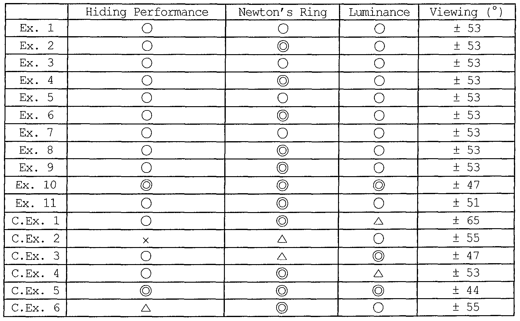
As is apparent from the results of evaluation of the
above properties, in the examples in which the difference in refractive index between the binder resin of the light diffusion layer and the particles of the light diffusion layer was grater than 0.05, hiding performance was superior and luminance and viewing angle were appraised to be at an appropriate level. In the case of the multifunctional optical film of Comparative Index 6 in which the difference in refractive index between the binder resin and the light- diffusing particles was not greater than 0.05, hiding performance was inferior to that of the examples.
Further, luminance, hiding performance and light interference of the examples according to the present invention were superior to the extent of Comparative Example 5 in which the light diffusion film, the prism film, and the protective film were layered, and the viewing angle was much wider than the case in which the light diffusion film, the prism film, and the protective film were layered.
Therefore, the multifunctional optical film according to the present invention and the backlight unit assembly comprising the same were confirmed to exhibit superior hiding performance, prevent light interference, and increase the efficient use of a light source while minimizing the loss of light, thus realizing luminance approximately equal to that of a conventional case where the light diffusion film and the prism film were separately
used. Also, the viewing angle was widened, thereby solving the problems due to the use of a plurality of films and remarkably reducing the manufacturing process and costs thereof.
Claims
[CLAIMS] [Claim l]
A multifunctional optical film, comprising: a transparent substrate layer; a light diffusion layer formed on one surface of the transparent substrate layer and including a binder resin and light-diffusing particles, in which a difference in refractive index between the light-diffusing particles and the binder resin is greater than 0.05; and a prism layer formed on the light diffusion layer.
[Claim 2]
The multifunctional optical film according to claim 1, wherein the light diffusion layer comprises 100 parts by weight of the binder resin and 10-500 parts by weight of light-diffusing particles having a particle size of l~50 jWin.
[Claim 3]
The multifunctional optical film according to claim 1, further comprising a bottom layer formed on the other surface of the transparent substrate layer and including a binder resin and particles.
[Claim 4]
The multifunctional optical film according to claim 3, wherein the particles of the bottom layer are identical to or different from the light-diffusing particles of the light diffusion layer.
[Claim 5] The multifunctional optical film according to claim
1, wherein the prism layer has a refractive index 0.01-0.2 higher than that of the binder resin of the light diffusion layer.
[Claim 6]
The multifunctional optical film according to claim 1, wherein the prism layer is imparted with a linear or non-linear array pattern of any structure selected from among a polypyramidal structure, a conical structure, a hemispherical structure, and a non-spherical structure.
[Claim 7]
A backlight unit assembly, comprising: the multifunctional optical film of any one of claims 1 to 6; and a light diffusion film disposed on any one surface of the multifunctional optical film.
[Claim 8] A backlight unit assembly, comprising: the multifunctional optical film of any one of claims 1 to 6; and a prism film disposed on any one surface of the multifunctional optical film.
[Claim 9]
A backlight unit assembly, comprising: the multifunctional optical film of any one of claims 1 to 6; and a protective film disposed on any one surface of the multifunctional optical film.
Priority Applications (1)
| Application Number | Priority Date | Filing Date | Title |
|---|---|---|---|
| CN2008801058214A CN101802654B (en) | 2007-09-07 | 2008-09-03 | Multifunctional optical film |
Applications Claiming Priority (2)
| Application Number | Priority Date | Filing Date | Title |
|---|---|---|---|
| KR10-2007-0090815 | 2007-09-07 | ||
| KR1020070090815A KR100988764B1 (en) | 2007-09-07 | 2007-09-07 | Optical Composite Film |
Publications (2)
| Publication Number | Publication Date |
|---|---|
| WO2009031806A2 true WO2009031806A2 (en) | 2009-03-12 |
| WO2009031806A3 WO2009031806A3 (en) | 2009-05-07 |
Family
ID=40429532
Family Applications (1)
| Application Number | Title | Priority Date | Filing Date |
|---|---|---|---|
| PCT/KR2008/005174 Ceased WO2009031806A2 (en) | 2007-09-07 | 2008-09-03 | Multi-functional optical film |
Country Status (4)
| Country | Link |
|---|---|
| KR (1) | KR100988764B1 (en) |
| CN (1) | CN101802654B (en) |
| TW (1) | TW200925729A (en) |
| WO (1) | WO2009031806A2 (en) |
Families Citing this family (3)
| Publication number | Priority date | Publication date | Assignee | Title |
|---|---|---|---|---|
| US9366800B2 (en) * | 2012-03-30 | 2016-06-14 | Kimoto Co., Ltd. | Edge light-type backlight device and light diffusion member |
| CN103293575A (en) * | 2013-05-10 | 2013-09-11 | 张家港康得新光电材料有限公司 | Diffusion and brightness enhancement film and method for manufacturing same |
| TWI667431B (en) * | 2018-12-19 | 2019-08-01 | 明新學校財團法人明新科技大學 | Laser illumination device |
Family Cites Families (7)
| Publication number | Priority date | Publication date | Assignee | Title |
|---|---|---|---|---|
| CN1187639C (en) * | 2001-07-13 | 2005-02-02 | 兴隆发电子股份有限公司 | Manufacturing method of light guide plate and mold thereof |
| JP4010542B2 (en) * | 2002-06-27 | 2007-11-21 | 日東電工株式会社 | Light diffusing sheet, optical element and image display device |
| JP2004045472A (en) * | 2002-07-09 | 2004-02-12 | Dainippon Printing Co Ltd | Light diffusion film, method for manufacturing the same, surface light source device, and liquid crystal display device |
| KR100601759B1 (en) * | 2003-11-26 | 2006-07-14 | 주식회사 코오롱 | Light diffusion film for LCD back-light unit |
| KR100930065B1 (en) * | 2004-01-08 | 2009-12-08 | 에스케이씨하스디스플레이필름(유) | Prism sheet for backlight unit, backlight unit and liquid crystal display device using same |
| CN100555005C (en) * | 2005-06-06 | 2009-10-28 | 旭硝子株式会社 | Light diffusion plate and method for manufacturing same |
| KR100909427B1 (en) * | 2005-07-27 | 2009-07-28 | 주식회사 코오롱 | Light control film |
-
2007
- 2007-09-07 KR KR1020070090815A patent/KR100988764B1/en not_active Expired - Fee Related
-
2008
- 2008-09-03 WO PCT/KR2008/005174 patent/WO2009031806A2/en not_active Ceased
- 2008-09-03 CN CN2008801058214A patent/CN101802654B/en not_active Expired - Fee Related
- 2008-09-04 TW TW097133991A patent/TW200925729A/en unknown
Also Published As
| Publication number | Publication date |
|---|---|
| WO2009031806A3 (en) | 2009-05-07 |
| CN101802654A (en) | 2010-08-11 |
| KR100988764B1 (en) | 2010-10-25 |
| CN101802654B (en) | 2012-05-30 |
| TW200925729A (en) | 2009-06-16 |
| KR20090025736A (en) | 2009-03-11 |
Similar Documents
| Publication | Publication Date | Title |
|---|---|---|
| US8506149B2 (en) | Optical sheets | |
| US20110026124A1 (en) | Multi-functional optic film | |
| KR100980072B1 (en) | Optical Composite Film | |
| WO2008150081A1 (en) | Eco-optical sheet | |
| KR100920645B1 (en) | Prism Composite Film | |
| KR100909427B1 (en) | Light control film | |
| US20100055409A1 (en) | Optical composite and method of manufacturing the same | |
| WO2009031806A2 (en) | Multi-functional optical film | |
| TW201024811A (en) | Light-diffusing film for back light unit of LCD and manufacturing method thereof | |
| KR100980068B1 (en) | Optical Composite Film | |
| KR101087026B1 (en) | Optical Composite Film | |
| KR20120139283A (en) | Backlight unit assembly | |
| WO2008082248A1 (en) | Optical composite and method of manufacturing the same | |
| WO2009069977A2 (en) | Multi-functional optic sheet | |
| KR20090064258A (en) | Light diffusion | |
| KR101370167B1 (en) | Backlight unit assembly | |
| KR100902156B1 (en) | Light control film | |
| KR100544518B1 (en) | Prism film with minimal light loss | |
| KR100906984B1 (en) | Backlight unit assembly | |
| KR101353845B1 (en) | Optical sheet having optical pattern layer | |
| WO2008115008A1 (en) | Optical sheets | |
| KR102014307B1 (en) | Optical film for mobile display | |
| KR101155277B1 (en) | Optic complex member | |
| KR101182080B1 (en) | Light Diffusion member | |
| KR20090128754A (en) | Optical composite members |
Legal Events
| Date | Code | Title | Description |
|---|---|---|---|
| WWE | Wipo information: entry into national phase |
Ref document number: 200880105821.4 Country of ref document: CN |
|
| 121 | Ep: the epo has been informed by wipo that ep was designated in this application |
Ref document number: 08793659 Country of ref document: EP Kind code of ref document: A2 |
|
| NENP | Non-entry into the national phase |
Ref country code: DE |
|
| 122 | Ep: pct application non-entry in european phase |
Ref document number: 08793659 Country of ref document: EP Kind code of ref document: A2 |