WO2008105909A2 - Optimal beam pattern synthesis via matrix weighting - Google Patents
Optimal beam pattern synthesis via matrix weighting Download PDFInfo
- Publication number
- WO2008105909A2 WO2008105909A2 PCT/US2007/074739 US2007074739W WO2008105909A2 WO 2008105909 A2 WO2008105909 A2 WO 2008105909A2 US 2007074739 W US2007074739 W US 2007074739W WO 2008105909 A2 WO2008105909 A2 WO 2008105909A2
- Authority
- WO
- WIPO (PCT)
- Prior art keywords
- array
- constraint
- vector
- subject
- determining
- Prior art date
- Legal status (The legal status is an assumption and is not a legal conclusion. Google has not performed a legal analysis and makes no representation as to the accuracy of the status listed.)
- Ceased
Links
Classifications
-
- H—ELECTRICITY
- H01—ELECTRIC ELEMENTS
- H01Q—ANTENNAS, i.e. RADIO AERIALS
- H01Q3/00—Arrangements for changing or varying the orientation or the shape of the directional pattern of the waves radiated from an antenna or antenna system
- H01Q3/26—Arrangements for changing or varying the orientation or the shape of the directional pattern of the waves radiated from an antenna or antenna system varying the relative phase or relative amplitude of energisation between two or more active radiating elements; varying the distribution of energy across a radiating aperture
- H01Q3/30—Arrangements for changing or varying the orientation or the shape of the directional pattern of the waves radiated from an antenna or antenna system varying the relative phase or relative amplitude of energisation between two or more active radiating elements; varying the distribution of energy across a radiating aperture varying the relative phase between the radiating elements of an array
Definitions
- the subject invention was made with government support under a research project supported by the Defense Advanced Research Projects Agency (DARPA), Contract No. HROO 11 -06- 1-0031 , the Air Force, Contract No. FA8721-05-C-0002. and by the National Science Foundation, Contract No. CCF-0634786.
- DRPA Defense Advanced Research Projects Agency
- Antenna array plays an important role in a wide span of applications including, for example, radar, sonar, communications, aeroacoustic noise measurement, and biomedical imaging.
- One of the fundamental problems in array signal processing is array pattern synthesis.
- a conventional approach of using weight vectors at the array output for array pattern synthesis can be referred to as the Vector Weighting Approaches (VWA).
- VWA Vector Weighting Approaches
- a vector of complex-valued weights is designed, applied to the sensor outputs, and the weighted sensor outputs are coherently summed up to form a desired beampattern [1-7].
- the solutions cannot be obtained efficiently and have no guarantee on their global optimality.
- the optimal array pattern can be recovered using standard spectral factorization techniques [8] — [10].
- these techniques are not suitable for nonuniform arrays.
- related designs with norm constraints on the weight vector were presented in [5].
- the VWA based designs for non-uniform linear arrays are non-convex and hence are NP-hard.
- two iterative algorithms were used to obtain local solutions with no guarantee on their global optimality.
- SDR Semidefmite Relaxation
- Adaptive arrays such as the standard Capon beamformer [12], adjust the weight vector adaptively according to the incoming signals. Adaptive arrays can have much better resolution, lower sidelobe levels, and much better interference rejection capabilities than their data- independent counterparts [I].
- the beampattern synthesis methods for adaptive arrays have been considered in [6], [13], [14] for linear arrays and 2 -D non-uniform arrays.
- [13] and [14] designs with the capability of peak sidelobe level control in adaptive arrays were presented using the analytical and convex optimization approaches, respectively. However, these designs do not control the main-beam shape.
- a method was presented in [6], where both the main-beam shape and the peak sidelobe level can be controlled to a certain extent with an iterative algorithm. However, it cannot control the peak sidelobe level and main- beam width precisely according to prescribed parameters.
- Embodiments of the subject invention relate to a method and apparatus for processing a plurality of signals from a sensor array requiring beam pattern synthesis.
- Embodiments of the invention relate to powerful and flexible beampattern synthesis techniques for antenna or ultrasound transducer arrays.
- Embodiments of the invention can be utilized with arrays in, for example, radar, sonar, communications, aeroacoustic noise measurement, and biomedical imaging. Examples of biomedical imaging array include ultrasound and microwave.
- Specific embodiments can incorporate a method that can be referred to as Matrix Weighting Approaches (MWA).
- MWA Matrix Weighting Approaches
- an optimal array pattern synthesis can be achieved with an arbitrary array.
- Embodiments of the subject MWA can utilize weight matrices at the array output. The use of weight matrices can provide improved flexibility for optimal array pattern synthesis.
- Embodiments of the subject method can be referred to as the data-adaptive MWA, which can also be referred to as the Adaptive WEighting of Signals via One Matrix Entity (AWESOME).
- Additional embodiments pertain to data-independent MWA designs, including, but not limited to, the beampattern matching, minimum sidelobe designs, and the constant beamwidth design for wideband array.
- globally optimal solutions can be determined efficiently for MWA.
- Convex optimization formulations can be used to determine globally optimal solutions.
- Certain embodiments of MWA can be considered as the Semidefmite Relaxation (SDR) of the VWA counterpart.
- SDR Semidefmite Relaxation
- Numerical examples presented show that embodiments of the data-adaptive AWESOME can allow for strict controls of main-beam shape and peak sidelobe level.
- the numerical examples also show that the capability of adaptive nulling of strong interferences and jammers can be maintained while controlling mainbeam shape and peak sidelobe level.
- Embodiments of the data-adaptive AWESOME have been shown to be robust against steering vector errors, small sample size problems, as well as interferences highly correlated or coherent with the signal-of-interest.
- Embodiments of data-adaptive AWESOME can have an improved performance in parameter estimations.
- the numerical examples also show that embodiments of the data- independent MWA can achieve much better beampattern synthesis compared to the VWA counterpart.
- Embodiments of the invention can provide a convenient way to deal with the open problem of optimal shading design for arbitrary arrays under various practical constraints.
- Embodiments of the invention incorporating MWA can extend the working frequency band of a practical array, SADA, used for aeroacoustic wideband noise measurement, from the original 10 -40 KHz to 8 - 65 KHz.
- Figures 1A-1D show a comparison of beam patterns from 100 Monte Carlo trials obtained via several adaptive beam forming methods.
- Figures 2A-2B show a comparison of beam patterns formed by several data-adaptive methods.
- Figures 3A-3B show a comparison of power estimates for the Signal of Interest (SOI) via several data-adaptive methods.
- SOI Signal of Interest
- Figure 4 shows a comparison of power estimates for the Signal of Interest (SOI) versus the variance of the array steering vector perturbation when the interference power is 20 dB.
- SOI Signal of Interest
- Figure 5 shows a comparison of SOI power estimates versus the correlation coefficient between the SOI and the 50 dB interference obtained via several data-adaptive methods using the theoretical R .
- Figures 6A-6B show a comparison of SOI power estimates versus the number of interferences obtained using the theoretical R .
- Figures 7A-7B show data-independent MWA and VWA beam patterns synthesized for 5-element Uniform Linear Arrays (ULA) via beampattern matching design, with each desired pulse width of 20° and under the uniform elemental gain constraint.
- ULA Uniform Linear Arrays
- Figures 8A-8B show MWA and VWA beam patterns synthesized for 10-element ULA via minimum sidelobe level design with the 3dB main-beam width equal to 20° and under the uniform elemental gain constraint.
- Figures 9A-9D show wideband constant beam width designs for ULA and MRA obtained via the MWA minimum side lobe level design under the total gain constraint.
- Figures 10A-10H show beam patterns for Small Aperture Directional Array (SADA) at various frequencies.
- SADA Small Aperture Directional Array
- Embodiments of the subject invention relate to a method and apparatus for processing a plurality of signals from a sensor array requiring beam pattern synthesis.
- Embodiments of the invention relate to powerful and flexible beampattern synthesis techniques for antenna or ultrasound transducer arrays.
- Embodiments of the invention can be utilized with arrays in, for example, radar, sonar, communications, aeroacoustic noise measurement, and biomedical imaging. Examples of biomedical imaging array include ultrasound and microwave.
- Specific embodiments can incorporate a method that can be referred to as Matrix Weighting Approaches (MWA).
- MWA Matrix Weighting Approaches
- an optimal array pattern synthesis can be achieved with an arbitrary array.
- Embodiments of the subject MWA can utilize weight matrices at the array output.
- Embodiments of the subject method can be referred to as the data- adaptive MWA, which can also be referred to as the Adaptive WEighting of Signals via One Matrix Entity (AWESOME).
- Additional embodiments pertain to data-independent MWA designs, including, but not limited to, the beampattern matching, minimum sidelobe designs, and the constant beamwidth design for wideband array.
- globally optimal solutions can be determined efficiently for MWA.
- Convex optimization formulations can be used to determine globally optimal solutions.
- Certain embodiments of MWA can be considered as the Semidefmite Relaxation (SDR) of the VWA counterpart.
- SDR Semidefmite Relaxation
- Numerical examples presented show that embodiments of the data-adaptive AWESOME can allow for strict controls of main-beam shape and peak sidelobe level. The numerical examples also show that the capability of adaptive nulling of strong interferences and jammers can be maintained while controlling mainbeam shape and peak sidelobe level.
- Embodiments of the data-adaptive AWESOME have been shown to be robust against steering vector errors, small sample size problems, as well as interferences highly correlated or coherent with the signal-of-interest.
- Embodiments of data-dependent AWESOME can have an improved performance in parameter estimations.
- Embodiments of the data- independent MWA can achieve much better beampattern synthesis compared to the VWA counterpart.
- Embodiments of the invention can provide a convenient way to deal with the open problem of optimal shading design for arbitrary arrays under various practical constraints.
- Embodiments of the invention incorporating MWA can extend the working frequency band of a practical array, SADA, used for aeroacoustic wideband noise measurement, from the original 10 -40 KHz to 8 - 65 KHz.
- Embodiments for implementing the optimal array pattern synthesis via Matrix Weighting Approaches can focus on array power response designs since in many applications, such as for aeroacoustic noise measurement [15], [16], only the power response of the array is of interest. Additional embodiments involve the production of an output signal vector, which is useful for many beamspace processing applications (see, e.g., [17]).
- r denotes the transpose of a matrix or vector.
- • * denotes the conjugate transpose of a matrix or vector.
- X' 2 denotes the Hermitian square root of the matrix X .
- tr(X) denotes the trace, and X mm denotes the m th diagonal element of the matrix X .
- X > 0 means that X is a positive semi-definite matrix.
- vec(X) denotes a vector obtained by stacking the columns of X on top of each other, and ⁇ 8> denotes the Kronecker matrix product.
- C'" x " ( R m ⁇ " ) is the complex-valued (real-valued) matrix of dimension mx n .
- I is the identity matrix with its dimension determined from the content.
- a( ⁇ 0 ) is the array steering vector for the SOI, which is a known function of ⁇ 0 .
- e(n) is the residue term, which contains the noise as well as interferences and jammers.
- the array steering vector may have different expressions, depending on the array geometry and on whether the source is in the near- or far-field of the array. For the far-field linear array case, the steering vector a( ⁇ 0 ) is given by
- c is the speed of propagation
- / is the carrier frequency
- x m is the location of the m th array element.
- the signal received by the m th array element is weighted by a complex- valued scalar w m ' ; the weighted signals are summed to yield the array output.
- the corresponding power response of the array as a function of ⁇ is the array beampattern (see, e.g., [2] and Chapter 6 in [18]):
- the variable to be designed is the weight vector w , or equivalently, the weight matrix T subject to the rank-one constraint. Due to the non- convexity of the rank-one constraint [19], the general VWA design problems cannot be solved in polynomial time and the solutions cannot be guaranteed to be globally optimal (in some cases with particular constraints, the VWA design problems can be formulated as convex optimization problems [14]).
- the matrix weighting can be done in parallel so as to require little, if any, extra processing time.
- embodiments of MWA can be viewed as a filter-bank approach.
- Specific embodiments of MWA can seek to find an optimal T > 0 that gives a desired array beampattern.
- the design under the elemental uniform gain constraint becomes the phase- only problem [21], which is non-convex and much more difficult to solve.
- the solution to MWA can be used as an initial solution to the phase-only problem.
- the output signal vector obtained via MWA can be used in many beamspace processing applications (see, e.g., [17]).
- Adaptive arrays can be found in many applications including radar, sonar, aeroacoustics, communications, and medical imaging.
- One classical data-adaptive beamformer, the standard Capon beamformer [12], seeks to minimize the array output power, subject to the constraint that the SOI is passed through the beamformer without distortion.
- one inherent problem associated with the data-adaptive beamformer is the varying main-beam shape and the unmanageable peak sidelobe level, due to, for example, the inadequate estimation of the sample covariance matrix [13] or the changing interference environment. Yet in some applications, such as some applications in radar, sonar, and/or communications, the main-beam shape must be maintained and the peak sidelobe level must be lower than a prescribed value [6], [13].
- Another problem of Capon is that it is rather sensitive to the model errors, including the steering vector errors, the small sample size problems (which are shown in [22] to be equivalent to the steering vector mismatches), and the presence of interferences correlated (especially highly correlated or coherent) with SOI.
- AWESOME Adaptive WEighting of Signals via One Matrix Entity
- ⁇ 0 is the location parameter of the SOI
- ⁇ x and ⁇ 2 are the prescribed 3-dB points
- ⁇ is the desired peak sidelobe level
- ⁇ denotes the sidelobe region
- the interval (#, ,#,) is the 3- dB main-beam region
- the formulation in (8) - (13) is a Semi-Definite Program (SDP) [20] and can be solved efficiently via the SDP solvers (see, e.g, [24], [25]).
- SDP Semi-Definite Program
- the 3-dB main-beam width cannot be arbitrarily narrow given a certain peak sidelobe level ⁇ and vice versa, due to the well-known tradeoff between the beamwidth and the peak sidelobe level.
- the problem in (8) may become infeasible if these parameters are not properly chosen.
- the constraints for the main-beam region (12) can be active when the desired main- beam width is very wide and, optionally inactive when the desired main-beam is not very wide. They are used to prevent main-beam splitting.
- the estimated SOI power p s can be computed via
- Embodiments of the invention relate to the data-independent optimal designs based on MWA.
- Data- independent means we do not use the statistics of the received data.
- a specific embodiment of data-independent MWA can utilize a beampattern match design, assume that we have a desired beampattern P tl ( ⁇ ) defined over a region of interest
- a > 0 is a variable to control the magnitude of the desired beampattern P d ( ⁇ ) .
- the problem is a convex optimization problem.
- the problem is a Semi-definite Quadratic Programming (SQP) problem [27] since this received beampattern design problem is a dual problem to the MIMO transmit beampattern design problem considered in [26].
- SQL Semi-definite Quadratic Programming
- the matrix Y above could be rank deficient.
- the rank of T is 2Af .
- the rank deficiency of Y does not pose any serious problem for the SQP solver we used (see, e.g., [25]).
- the beampattern matching design in (16) - (18) becomes the following SQP (see, e.g., [27]): min t subject to Y ] 2 P ⁇ (
- Specific embodiments can incorporate minimum sidelobe level design. These embodiments can be useful when it is important to control the peak sidelobe level of the beampattern (see, e.g., [6], [13J), while maintaining the shape of the main-lobe (e.g., direction, prescribed 3-dB beamwidth, etc.). For such applications, the following is an example of a minimum sidelobe level design that can be used.
- the constraint (29) guarantees that the gain in the 3-dB main-beam region is at least half of the gain at ⁇ 0 .
- the constraints (29) are used to prevent main-beam splitting and are active only in some cases.
- the formulation (27) - (32) is a SDP [20] and can be solved efficiently in polynomial time using public domain software (e.g., [25]). Again, specific embodiments may modify (28) and/or modify and use one or more of the constraints in (28), (29), (30). and (31). Additional constraints can be added to the formulation as well.
- a constant beamwidth design for wideband arrays can be utilized.
- Beamformers with frequency-invariant main-beam widths are desirable in many wideband signal processing applications, such as aeroacoustics [15], [16], [28], radar, sonar, and communications [29].
- a widely used wideband array processing approach, which can be utilized in embodiments of the invention, is to sample the spectrum of the wideband signal at each array element output to form narrowband frequency bins, and then process the samples in each frequency bin separately using narrowband array processing techniques [23].
- Constant beamwidth beamformer can form consistent estimates of the source location and power across all frequency bins.
- the beamwidth of most beamformers decreases as the center frequency of the frequency bin increases, due to a larger effective array aperture at a higher frequency or a smaller wavelength.
- One way to mitigate this problem is to use shading, i.e, to apply frequency-dependent weights to the sensor outputs.
- shading schemes exist for regular arrays including ULA and Small Aperture Directional Array (SADA) [15]. Shading design for arbitrary arrays with various constraints still appears to be an open problem.
- Embodiments of the invention incorporating MWA can be applied to achieve constant beamwidth beampattern designs for wideband arrays.
- the minimum sidelobe level design of MWA can be used by specifying a common 3-dB main-beam width for all frequency bins, and then obtaining a weight matrix for each narrowband frequency bin using (27). The resulting beampattern for each frequency bin will have a constant main-beam width and the lowest possible sidelobe level.
- the beampattern matching design of MWA can also be modified for constant beamwidth design of wideband arrays.
- Embodiments of the invention can utilize AWESOME to achieve constant main-beam width across all frequency bins while retaining its adaptive array capabilities of adaptively suppressing interferences and jammers. In the numerical examples in the next section, minimum sidelobe level designs via MWA are analyzed.
- the inter-element spacings for the 5 -element MRA are 1, 3, 3, 2 [1], in the unit of half- wavelength at the carrier frequency (for narrowband signals).
- SADA (see [15] for more details) is a directional array designed for aeroacoustic noise measurement, and incorporates 33 microphones arranged in four circles of eight microphones each and one microphone at the array center. The maximum radius of the array is 3.89 inches.
- the performance of the data-adaptive AWESOME is compared with those of the standard Capon beamformer [12] and the Robust Capon Beamformer (RCB) [30].
- One strong interference is present at 40" .
- the SOI power estimates presented below are obtained via averaging over 100 Monte-Carlo trials.
- Figure IA corresponds to the standard Capon beamformer, where the peak sidelobe level is as high as about -1 dB and the pointing location of the main-beam varies from trial to trial.
- Figure IB shows that RCB [30] has a peak sidelobe level of about -10 dB, but the main-beam shape still varies slightly from one trial to another.
- AWESOME can effectively control the peak sidelobe level to below -16 dB, and maintain a constant main- beam shape from trial to trail.
- Capon beamformer fails to function properly and forms a null at T ; RCB 's gain at 0 " is above 0 dB; AWESOME maintains the main-beam shape and the peak sidelobe level.
- Figure 3 shows the SOI power estimates when the SOI power is 20 dB and the interference power is 60 dB.
- the main-beam shape and the peak sidelobe level specifications of AWESOME are the same as those for Figure 2.
- Figs. 5 (a) and 5(b) Figures 3A and 3B, respectively, show the SOI power estimates versus the snapshot number N with and without the 2° steering angle mismatch. The perturbing random variables are independent of each other.
- the steering vector varies from one Monte-Carlo trial to another for Figure 4. Note that AWESOME and RCB yield much more accurate SOI power estimates than the standard Capon beamformer.
- AWESOME performs similarly as RCB in most cases but outperforms RCB when the variance of the perturbing random variables is large.
- This advantage of AWESOME is a result of, at least in part, its strict main-beam shape control.
- Figure 5 shows the SOI power estimates as a function of the correlation coefficient between the SOI and the interference obtained using the theoretical R (i.e., N -» ⁇ ). The SOI power is 20 dB, and the interference power is 50 dB.
- AWESOME significantly outperforms both RCB and the standard Capon beamformer in the presence of highly correlated or coherent interference since the latter two algorithms fail to function properly when the correlation coefficient becomes close to 1.
- this embodiment of AWESOME will eventually fail since the peak sidelobe level of this embodiment of AWESOME is set to -40 dB and hence is not sufficient for the adequate suppression of the very strong interference.
- FIGS. 6A and 6B show the SOI power estimates obtained using the theoretical R when the interference powers are 40 dB and 60 dB, respectively.
- AWESOME outperforms RCB.
- AWESOME performs similarly as the standard Capon beamformer when the interference power is 40 dB, but the latter performs better when the interference power increases.
- An embodiment of the invention utilizes MWA: Beampattern Matching Design.
- An embodiment of the invention utilizes MWA: Minimum Sidelobe Level Design.
- Fig. 9 is obtained with a mesh grid size of 0.1 . Note that VWA fails to produce a proper main-beam and that the peak sidelobe level of the VWA beampattern is more than 5 dB higher than that of MWA.
- Embodiments of the invention can utilize MWA: Constant Beam width Design for Wideband Arrays.
- the MWA beampatterns maintain a constant 3-dB beamwidth across the frequency band.
- the sidelobe levels of MRA are higher than those of ULA because it is difficult to control the sidelobe levels of MRA.
- Figure 9C shows the 3-dB main-beam widths of MWA, which are compared with those of the DAS beamformer, as functions of the normalized frequency. The peak sidelobe level comparison is shown in Figure 9D. Note again that MWA can be used to achieve constant main-beam width across the frequency bins for both ULA and MRA. At lower frequencies, the peak sidelobe levels of MWA are slightly higher than those of DAS. but at higher frequencies, the peak sidelobe levels of MWA are lower (and much lower for ULA).
- r n ⁇ is the location of the m th sensor.
- the beampatterns using the minimum sidelobe level design (27) under the total gain constraint are obtained.
- the ranges of the x-axis and y-axis of the images are from -2 to 2 feet. (For comparison purposes, these parameters are set to be the same as those in [15].)
- the mesh grid size on both the x- and y-axes is 0.5 inches.
- the radius of the desired 3-dB circle for MWA is selected to be 4 inches, which is roughly the same as that achieved by the shading scheme in [15] at 10 - 40
- the beampatterns in Figs. Figures 10A- 1OD are obtained by using VMA shaded by the frequency-dependent weight vector designed in [15].
- the frequency-dependent weight vector was designed to maintain a constant beamwidth within the frequency band of 10 - 40
- the radius of the 3-dB circle at 8 KHz in Figure 1OA is wider than those at 20 and 40 KHz in Figures 1OB and 1OC, respectively.
- the radius of the 3-dB circle at 65 KHz in Fig. Figure 1OD is narrower than those at 20 and 40 KHz.
- the MWA beampatterns have a constant 3-dB circle and low sidelobe levels throughout the 8 to 65 KHz frequency band, as shown in Figures 10E- 1OH. This demonstrates that MWA is capable of extending the constant beamwidth working frequency band of SADA to 8 - 65 KHz.
- the optimal T determined by MWA has only one dominant eigenvalue, which means that better weighting vectors than those presented in [15J have been found.
Landscapes
- Radio Transmission System (AREA)
Description
DESCRIPTION
OPTIMAL BEAM PATTERN SYNTHESIS VIA MATRIX WEIGHTING
The subject invention was made with government support under a research project supported by the Defense Advanced Research Projects Agency (DARPA), Contract No. HROO 11 -06- 1-0031 , the Air Force, Contract No. FA8721-05-C-0002. and by the National Science Foundation, Contract No. CCF-0634786.
Cross-Reference to Related Application
The present application claims the benefit of U.S. Application Serial No. 60/833,948, filed July 28. 2006, which is hereby incorporated by reference herein in its entirety, including any figures, tables, or drawings.
Background of Invention
Antenna array plays an important role in a wide span of applications including, for example, radar, sonar, communications, aeroacoustic noise measurement, and biomedical imaging. One of the fundamental problems in array signal processing is array pattern synthesis. A conventional approach of using weight vectors at the array output for array pattern synthesis, can be referred to as the Vector Weighting Approaches (VWA). In conventional formulation for this problem, a vector of complex-valued weights is designed, applied to the sensor outputs, and the weighted sensor outputs are coherently summed up to form a desired beampattern [1-7]. In the conventional VWA frame work, the solutions cannot be obtained efficiently and have no guarantee on their global optimality. There is a long history of studying the array pattern synthesis problem using VWA
(see, e.g., [1], and the references therein). Recently, numerical approaches based on convex optimization techniques [2], [5], [7] have received much attention. Compared to the early analytical approaches, the recent approaches can handle more complicated design specifications and are able to obtain the global optimal solutions efficiently, as long as the design problems can be formulated as convex optimization problems. Applications of the convex optimization techniques to data-independent VWA beampattern synthesis were first introduced by Lebret et al. in [2] and both narrowband and wideband Uniform Linear Arrays (ULA) were considered. The design of beampattern for ULA is equivalent to a power spectral density (PSD) constrained finite impulse response filter design problem. Once the optimal
PSD is designed, the optimal array pattern can be recovered using standard spectral factorization techniques [8] — [10]. However, these techniques are not suitable for nonuniform arrays. For non-uniform arrays, related designs with norm constraints on the weight vector were presented in [5]. However, the VWA based designs for non-uniform linear arrays are non-convex and hence are NP-hard. In [5], two iterative algorithms were used to obtain local solutions with no guarantee on their global optimality. The idea of using Semidefmite Relaxation (SDR) for array beampattern synthesis and for the related problem of two- dimensional filtering was presented in the recent work [7], [1 1]. However, their approaches are also based on weighting vectors and are obtained by modifying the relaxed solutions via some iterative methods, which provide no guarantee on their global optimality.
In the presence of strong interferences and jammers, data-adaptive methods are needed due to their adaptive nulling ability to suppress interferences and jammers. Adaptive arrays, such as the standard Capon beamformer [12], adjust the weight vector adaptively according to the incoming signals. Adaptive arrays can have much better resolution, lower sidelobe levels, and much better interference rejection capabilities than their data- independent counterparts [I]. The beampattern synthesis methods for adaptive arrays have been considered in [6], [13], [14] for linear arrays and 2 -D non-uniform arrays. In [13] and [14], designs with the capability of peak sidelobe level control in adaptive arrays were presented using the analytical and convex optimization approaches, respectively. However, these designs do not control the main-beam shape. A method was presented in [6], where both the main-beam shape and the peak sidelobe level can be controlled to a certain extent with an iterative algorithm. However, it cannot control the peak sidelobe level and main- beam width precisely according to prescribed parameters.
Brief Summary
Embodiments of the subject invention relate to a method and apparatus for processing a plurality of signals from a sensor array requiring beam pattern synthesis. Embodiments of the invention relate to powerful and flexible beampattern synthesis techniques for antenna or ultrasound transducer arrays. Embodiments of the invention can be utilized with arrays in, for example, radar, sonar, communications, aeroacoustic noise measurement, and biomedical imaging. Examples of biomedical imaging array include ultrasound and microwave. Specific embodiments can incorporate a method that can be referred to as Matrix Weighting Approaches (MWA). In a specific embodiment, an optimal array pattern synthesis can be
achieved with an arbitrary array. Embodiments of the subject MWA can utilize weight matrices at the array output. The use of weight matrices can provide improved flexibility for optimal array pattern synthesis.
Embodiments of the subject method can be referred to as the data-adaptive MWA, which can also be referred to as the Adaptive WEighting of Signals via One Matrix Entity (AWESOME). Additional embodiments pertain to data-independent MWA designs, including, but not limited to, the beampattern matching, minimum sidelobe designs, and the constant beamwidth design for wideband array. In specific embodiments of these designs, globally optimal solutions can be determined efficiently for MWA. Convex optimization formulations can be used to determine globally optimal solutions. Certain embodiments of MWA can be considered as the Semidefmite Relaxation (SDR) of the VWA counterpart. Numerical examples presented show that embodiments of the data-adaptive AWESOME can allow for strict controls of main-beam shape and peak sidelobe level. The numerical examples also show that the capability of adaptive nulling of strong interferences and jammers can be maintained while controlling mainbeam shape and peak sidelobe level. Embodiments of the data-adaptive AWESOME have been shown to be robust against steering vector errors, small sample size problems, as well as interferences highly correlated or coherent with the signal-of-interest. Embodiments of data-adaptive AWESOME can have an improved performance in parameter estimations. In addition, the numerical examples also show that embodiments of the data- independent MWA can achieve much better beampattern synthesis compared to the VWA counterpart. Embodiments of the invention can provide a convenient way to deal with the open problem of optimal shading design for arbitrary arrays under various practical constraints. Embodiments of the invention incorporating MWA can extend the working frequency band of a practical array, SADA, used for aeroacoustic wideband noise measurement, from the original 10 -40 KHz to 8 - 65 KHz.
Brief Description of Drawings
Figures 1A-1D show a comparison of beam patterns from 100 Monte Carlo trials obtained via several adaptive beam forming methods.
Figures 2A-2B show a comparison of beam patterns formed by several data-adaptive methods.
Figures 3A-3B show a comparison of power estimates for the Signal of Interest (SOI) via several data-adaptive methods.
Figure 4 shows a comparison of power estimates for the Signal of Interest (SOI) versus the variance of the array steering vector perturbation when the interference power is 20 dB.
Figure 5 shows a comparison of SOI power estimates versus the correlation coefficient between the SOI and the 50 dB interference obtained via several data-adaptive methods using the theoretical R .
Figures 6A-6B show a comparison of SOI power estimates versus the number of interferences obtained using the theoretical R .
Figures 7A-7B show data-independent MWA and VWA beam patterns synthesized for 5-element Uniform Linear Arrays (ULA) via beampattern matching design, with each desired pulse width of 20° and under the uniform elemental gain constraint.
Figures 8A-8B show MWA and VWA beam patterns synthesized for 10-element ULA via minimum sidelobe level design with the 3dB main-beam width equal to 20° and under the uniform elemental gain constraint.
Figures 9A-9D show wideband constant beam width designs for ULA and MRA obtained via the MWA minimum side lobe level design under the total gain constraint.
Figures 10A-10H show beam patterns for Small Aperture Directional Array (SADA) at various frequencies.
Detailed Disclosure
Embodiments of the subject invention relate to a method and apparatus for processing a plurality of signals from a sensor array requiring beam pattern synthesis. Embodiments of the invention relate to powerful and flexible beampattern synthesis techniques for antenna or ultrasound transducer arrays. Embodiments of the invention can be utilized with arrays in, for example, radar, sonar, communications, aeroacoustic noise measurement, and biomedical imaging. Examples of biomedical imaging array include ultrasound and microwave. Specific embodiments can incorporate a method that can be referred to as Matrix Weighting Approaches (MWA). In a specific embodiment, an optimal array pattern synthesis can be achieved with an arbitrary array. Embodiments of the subject MWA can utilize weight matrices at the array output. The use of weight matrices can provide improved flexibility for optimal array pattern synthesis.
Embodiments of the subject method can be referred to as the data- adaptive MWA, which can also be referred to as the Adaptive WEighting of Signals via One Matrix Entity (AWESOME). Additional embodiments pertain to data-independent MWA designs, including, but not limited to, the beampattern matching, minimum sidelobe designs, and the constant beamwidth design for wideband array. In specific embodiments of these designs, globally optimal solutions can be determined efficiently for MWA. Convex optimization formulations can be used to determine globally optimal solutions. Certain embodiments of MWA can be considered as the Semidefmite Relaxation (SDR) of the VWA counterpart. Numerical examples presented show that embodiments of the data-adaptive AWESOME can allow for strict controls of main-beam shape and peak sidelobe level. The numerical examples also show that the capability of adaptive nulling of strong interferences and jammers can be maintained while controlling mainbeam shape and peak sidelobe level. Embodiments of the data-adaptive AWESOME have been shown to be robust against steering vector errors, small sample size problems, as well as interferences highly correlated or coherent with the signal-of-interest. Embodiments of data-dependent AWESOME can have an improved performance in parameter estimations.
In addition, the numerical examples also show that embodiments of the data- independent MWA can achieve much better beampattern synthesis compared to the VWA counterpart. Embodiments of the invention can provide a convenient way to deal with the open problem of optimal shading design for arbitrary arrays under various practical constraints. Embodiments of the invention incorporating MWA can extend the working frequency band of a practical array, SADA, used for aeroacoustic wideband noise measurement, from the original 10 -40 KHz to 8 - 65 KHz.
Embodiments for implementing the optimal array pattern synthesis via Matrix Weighting Approaches (MWA) can focus on array power response designs since in many applications, such as for aeroacoustic noise measurement [15], [16], only the power response of the array is of interest. Additional embodiments involve the production of an output signal vector, which is useful for many beamspace processing applications (see, e.g., [17]).
The notations adopted hereafter are standard. (-)r denotes the transpose of a matrix or vector. (•)* denotes the conjugate transpose of a matrix or vector. | • | denotes the absolute value, and • denotes the Euclidean norm of a vector. X' 2 denotes the Hermitian square root of the matrix X . tr(X) denotes the trace, and Xmm denotes the m th diagonal element of the
matrix X . X > 0 means that X is a positive semi-definite matrix. vec(X) denotes a vector obtained by stacking the columns of X on top of each other, and <8> denotes the Kronecker matrix product. C'"x" ( Rm<" ) is the complex-valued (real-valued) matrix of dimension mx n . I is the identity matrix with its dimension determined from the content. Consider an M -element array with an arbitrary array geometry. Let s{ή) denote the unknown waveform of a narrowband signal-of-interest (SOI) The wideband signal case can be addressed by, for example, dividing waveform into narrowband frequency bins. Let θ0 denote a generic source location parameter for the SOI, which may be the direction-of-arrival of SOI in the far-field of an array, or the 3-D coordinate of SOI in the near-field of an array. The model for the received data vector is given by (see, e.g., [18]):
y(«) = a(0o>(«) + e(«), n = \,-, N, (1) where y(«) is the n th received data vector or the n th snapshot, n = \,- - -, N , with N denoting the snapshot number; a(θ0) is the array steering vector for the SOI, which is a known function of θ0. and e(n) is the residue term, which contains the noise as well as interferences and jammers. The array steering vector may have different expressions, depending on the array geometry and on whether the source is in the near- or far-field of the array. For the far-field linear array case, the steering vector a(θ0) is given by

where c is the speed of propagation, / is the carrier frequency, and xm is the location of the m th array element.
In VWA, the signal received by the m th array element is weighted by a complex- valued scalar wm ' ; the weighted signals are summed to yield the array output.
w = [Wp...,H>w ] e CXM (3)
The corresponding power response of the array as a function of θ is the array beampattern (see, e.g., [2] and Chapter 6 in [18]):
PiJS ) - |w*n (fl i|2 -- a|fl ιVw+a ( rf ι
 (4)
(4)
T = WW' = CM y 'xt
where the matrix has rank one.
In VWA beampattern synthesis, the variable to be designed is the weight vector w , or equivalently, the weight matrix T subject to the rank-one constraint. Due to the non- convexity of the rank-one constraint [19], the general VWA design problems cannot be solved in polynomial time and the solutions cannot be guaranteed to be globally optimal (in some cases with particular constraints, the VWA design problems can be formulated as convex optimization problems [14]).
In specific embodiment array pattern synthesis via MWA, we remove the rank-1 constraint on T and allow T to have rank higher than one. The resulting formulation is the Semidefmite Relaxation (SDR) [19], [20] of the corresponding VWA formulation for the same beampattern synthesis problem. SDR is often used to obtain approximate (in the sense that the solution has rank larger than one) solutions to rank constrained optimization problems [19], [20]. Although it seems that MWA has increased the system implementation complexity, our numerical examples show that the optimal solution of T is usually not full rank, and the number of its dominant eigenvalues K is often quite small, which means that specific embodiments utilizing MWA can require K times the hardware implementation cost of VWA. In specific embodiments, the matrix weighting can be done in parallel so as to require little, if any, extra processing time. Once T is determined, we let T = UΣU* and let W = ∑1 2U , where the columns of U are the eigenvectors of T and the diagonal elements of the diagonal matrix Σ are the corresponding eigenvalues. Then
T = WW*, (5)
where W = [W1,- ■ -,wλ ] e Cu'κ , with wA denoting the k th weight vector in Fig. 2. Then the power response of the array as a function of θ is the array beampattern of MWA:
P{θ) = a* (0)Ta(0) = a* røWW'a(θ) = ∑ [a* (0)wA j . (6)
Therefore, embodiments of MWA can be viewed as a filter-bank approach. Specific embodiments of MWA can seek to find an optimal T > 0 that gives a desired array beampattern.
The trace of T can be referred to as the total gain of the weight matrix W in MWA and can determine the power amplification at the array output. Note that:
tr(T) = tr| XwiW; w,. w W , (7)
. k=l J k=\ k=] k = l
where we have use the fact that tr(AB) = tr(BA) . Hence the total gain constraint on the array weights is the trace constraint on T . Embodiments of the invention can incorporate one or both of the following two types of gain constraints: i) the total gain constraint, which requires tr(T) = c , where c is some given constant; ii) the elemental uniform gain constraint, i.e., Tmm = c/M , m = \,- - -,M , which requires that each antenna element contributes equal gain to the array output. Both constraints are linear in T and hence are easy to incorporate into the optimal array designs.
In VWA, the design under the elemental uniform gain constraint becomes the phase- only problem [21], which is non-convex and much more difficult to solve. In an embodiment, the solution to MWA can be used as an initial solution to the phase-only problem.
The W determined from T via (5) is not unique since T = WPP*W* for any unitary matrix P with P*P = PP* = I . Hence we can pick P to be a diagonal matrix with each of its diagonal elements unit modulus but with the phase adjusted so that each element of W*a(#0) is real-valued. For VWA, i.e., with T being rank-1 , this choice of P together with a* (θo)Ta(θo) = 1 yields the distortionless response constraint w*a((90) = 1 .
The output signal vector obtained via MWA can be used in many beamspace processing applications (see, e.g., [17]). Embodiments of the invention can utilize MWA to produce an output signal vector W*y(«) , n = \,- - -,N , These output signal vectors can be used in various beam space processing applications.
Adaptive arrays can be found in many applications including radar, sonar, aeroacoustics, communications, and medical imaging. One classical data-adaptive beamformer, the standard Capon beamformer [12], seeks to minimize the array output power, subject to the constraint that the SOI is passed through the beamformer without distortion.
However, one inherent problem associated with the data-adaptive beamformer is the varying main-beam shape and the unmanageable peak sidelobe level, due to, for example, the inadequate estimation of the sample covariance matrix [13] or the changing interference environment. Yet in some applications, such as some applications in radar, sonar, and/or communications, the main-beam shape must be maintained and the peak sidelobe level must
be lower than a prescribed value [6], [13]. Another problem of Capon is that it is rather sensitive to the model errors, including the steering vector errors, the small sample size problems (which are shown in [22] to be equivalent to the steering vector mismatches), and the presence of interferences correlated (especially highly correlated or coherent) with SOI. For more than three decades, many approaches have been proposed to make the adaptive beamformer robust [23]. However, the problems of maintaining the main-beam shape and controlling the peak sidelobe level of adaptive arrays still remain to be solved. Various embodiments of the invention utilizing the Adaptive WEighting of Signals via One Matrix Entity (AWESOME) algorithm can address one or more of these problems. Consider the data model in (1 ). Similar to the formulation of the Capon beamformer, the array output power can be minimized under the constraint of unit power gain for the SOI. One or more additional constraints can be introduced to control the 3-dB main-beam width as well as the peak sidelobe level. A specific embodiment of AWESOME is formulated as follows: min tr(RT) (8)
subject to a'(0o)Ta(0o) = l, (9) a*(0,)Ta(0,) = 0.5, / = 1,2, (10) a (μ,)Υa(μ,) ≤ ς, μ, e Ψ „ (11)
 T > 0. (13)
where θ0 is the location parameter of the SOI, θx and θ2 are the prescribed 3-dB points, ς is the desired peak sidelobe level, ψ( denotes the sidelobe region, the interval (#, ,#,) is the 3- dB main-beam region, and
R = -^∑y(«)y» 04)
N «=i
is the sample covariance matrix. Alternative embodiments can use another value in equation (9) rather than 1 and/or modify and use one or more of the constraints provided in equations (9). (10), (1 1), and (12). Additional constraints can be added to the AWESOME formulation
as well. The formulation in (8) - (13) is a Semi-Definite Program (SDP) [20] and can be solved efficiently via the SDP solvers (see, e.g, [24], [25]).
The 3-dB main-beam width cannot be arbitrarily narrow given a certain peak sidelobe level ς and vice versa, due to the well-known tradeoff between the beamwidth and the peak sidelobe level. The problem in (8) may become infeasible if these parameters are not properly chosen.
No constraint on the trace or the diagonal elements of T is imposed in this formulation since we already have the explicit gain constraint in (9). Again, the gain constraint in (9) can be modified in other embodiments. The constraints for the main-beam region (12) can be active when the desired main- beam width is very wide and, optionally inactive when the desired main-beam is not very wide. They are used to prevent main-beam splitting.
The estimated SOI power ps can be computed via
A = tr(RT). (15)
If we include with this AWESOME formulation the constraints that rank(T) = 1 and that the diagonal elements of T are equal, then (8) becomes the angle-only adaptive array problem discussed in [21]. The rank(T) = 1 constraint makes the angle-only problem non- convex. By dropping the rank-one constraint, we can obtain the SDR solution to the angle- only problem, which can be used as the initial solution to the phase-only problem and refined via, e.g., a Newton-like search method [19].
Embodiments of the invention relate to the data-independent optimal designs based on MWA. Data- independent means we do not use the statistics of the received data.
A specific embodiment of data-independent MWA can utilize a beampattern match design, assume that we have a desired beampattern Ptl(θ) defined over a region of interest
Ω . Let {/J, }l'=l be a fine grid of points covering Ω . An embodiment involves finding the matrix T > 0 such that P(θ) matches or rather approximates (in a mean-squared error (MSE) sense) the desired beampattern Pd{β) , over the region of interest Ω under either the elemental uniform gain constraint or the total gain constraint. Mathematically, we can solve the following problem:
 subject to Tmm = — , m = l,---,M, or tr(T) = c, (17)
M
T>0, (18) where V1 ≥ 0. / = 1,-- -,L , is the weighting factor for the /th grid point, a > 0 is a variable to control the magnitude of the desired beampattern Pd(θ) . In (16), the scaling factor a is introduced for the consideration that typically φ(θ) is given in a "normalized form" (e.g., satisfying ^" ' Pd(Mi) = O> and an appropriately scaled version of φ(θ) can be approximated, not φ(θ) itself.
Techniques similar to those used in [26] can be used to show that the problem is a convex optimization problem. In certain embodiments, the problem is a Semi-definite Quadratic Programming (SQP) problem [27] since this received beampattern design problem is a dual problem to the MIMO transmit beampattern design problem considered in [26]. Let r denote the M2xl real-valued vector made from Tmm (m = \,---,M) and the real and imaginary parts of Tmp, (m, p = 1, • ■ • ,M;p > m). Then, given the Hermitian symmetry of T , we can write: vec(T) = Jr, (19)
for a suitable M2χM2 matrix J whose elements are easily derived constants (0,±/',±l). Making use of (19) and of some simple properties of the vec operator, we have a* (μ, )Ta(μ, ) = vec [a* (μ, )Ta(μ, ;
=[a'C",)® a* (//,)] Jr
"' * (20)
Inserting (20) into (16) yields the following more compact form of the design cost function: 1 V- F T 12 Δ ;r (21) where the vector L ι=J a
P = (22)
contains all the variables and

The matrix Y above could be rank deficient. For example, in the case of an M -sensor ULA with half-wavelength or smaller inter-element spacing, it can be verified that the rank of T is 2Af . The rank deficiency of Y , however, does not pose any serious problem for the SQP solver we used (see, e.g., [25]).
By making use of (19) - (23), the beampattern matching design in (16) - (18) becomes the following SQP (see, e.g., [27]): min t subject to Y] 2P < (
7Ln (A) = TT > m = !, ■ ■ ■ , M, or tr(T) = c, M
T(P) > 0, (24)
where we have indicated explicitly the (linear) dependence of T on p . For practical values of the array size M , the SQP above can be efficiently solved on a personal computer using public domain software (see, e.g., [24], [25]). In some applications, we may wish that the synthesized beampattern at some given locations be exactly (or very close to) some values, or that one peak at a certain location to have exactly the same power (or of some ratio β ) as a different peak at another location. The first requirement can be met by adding the following equality constraints to the original formulation (16): (25) af ι /if jTaψ, "' — Ci - 1 — 1 ■ ■ . L . where {ζt} are the prescribed values and {μt} are the corresponding mesh grids. The second requirement can be added to (16) by using the following equality constraints:
a*( //A )Taι //fc i ~ ftι+ t //j ιTaι // ? ) . for some /, * j. (26)
where μk and μ are the locations at which we wish to have equal gain (or certain ratio).
The extended problems with the above additional constraints remain SQP's and can be solved efficiently using the aforementioned SQP solvers.
Specific embodiments can incorporate minimum sidelobe level design. These embodiments can be useful when it is important to control the peak sidelobe level of the beampattern (see, e.g., [6], [13J), while maintaining the shape of the main-lobe (e.g., direction, prescribed 3-dB beamwidth, etc.). For such applications, the following is an example of a minimum sidelobe level design that can be used. Assume that the main-beam is directed toward O0 , the prescribed 3-dB angles are 6> and O2 (the 3-dB beamwidth is O2 - O1 , with θ2 > θ0 and θx < 6>0 ), the 3-dB main-beam region is Ψ m and the sidelobe region is Ψs . Such a minimum sidelobe level design problem can be formulated as follows: min -t (27)
I subject to a (O0)Ta(O0) ^a (μp)Ta(μp) > t, /ιp e Ψs (28)
0 < a (θ0)Ta(θ0) -a (μp)Ta(μp) ≤ 0.5a (O0)Ta(O0), μp e Ψm (29)
0.5a* (O0 )Ta(0o) - a* (0, )Ta(0, ) = 0, / = 1,2, (30)
Tmm = c/M, m = \, -,M, or tr(T) = c, (31)
T > 0. (32) where the constraint (29) guarantees that the gain in the 3-dB main-beam region is at least half of the gain at θ0 . The constraints (29) are used to prevent main-beam splitting and are active only in some cases. The formulation (27) - (32) is a SDP [20] and can be solved efficiently in polynomial time using public domain software (e.g., [25]). Again, specific embodiments may modify (28) and/or modify and use one or more of the constraints in (28), (29), (30). and (31). Additional constraints can be added to the formulation as well.
In specific embodiments, some of the constraints in the minimum sidelobe level design can be relaxed. We can relax somewhat the constraints in (30) defining the 3-dB mainbeam width; for instance, we can replace them by
(0.5 - δ)a (O0)Ta(θ0) ≤ a (O1)Ta(O1) ≤ (0.5 + δ)a (O0)Ta(O0) J = 1, 2 , for some small number δ > 0 . Such a relaxation can lead to designs with lower peak sidelobe levels, since in some designs, such as for 2-D arrays, the problem can become infeasible without proper relaxation. If needed, we can also relax the elemental uniform gain constraints somewhat by allowing the elemental gain to be within a certain range around clM , while still maintaining the same total gain of c . Our numerical simulations show that such a relaxation can result in lower sidelobe levels and smoother beampatterns.
The VMA counterparts can be readily modified from the previously described beampattern matching or minimum sidelobe level beampattern designs by adding the constraint rank(T) = l to (16) and (27), respectively. However, due to the non-convexity of the rank constraint, the problem becomes much harder to solve and no globally optimal solution is guaranteed.
In the numerical examples to follow, the Newton-like algorithm presented in [19] was used. This algorithm uses the solution to SDR as an initial solution, and then uses the tangent- and-lift procedure to iteratively find the solution satisfying the rank-one constraint. Although the convergence of the Newton-like algorithm is not guaranteed [19], we did not encounter any numerical problem in our simulations.
In specific embodiments, a constant beamwidth design for wideband arrays can be utilized. Beamformers with frequency-invariant main-beam widths are desirable in many wideband signal processing applications, such as aeroacoustics [15], [16], [28], radar, sonar, and communications [29]. A widely used wideband array processing approach, which can be utilized in embodiments of the invention, is to sample the spectrum of the wideband signal at each array element output to form narrowband frequency bins, and then process the samples in each frequency bin separately using narrowband array processing techniques [23]. Constant beamwidth beamformer can form consistent estimates of the source location and power across all frequency bins. However, the beamwidth of most beamformers, such as the Delay-And-Sum (DAS) and the Capon methods [18], decreases as the center frequency of the frequency bin increases, due to a larger effective array aperture at a higher frequency or a smaller wavelength. One way to mitigate this problem is to use shading, i.e, to apply frequency-dependent weights to the sensor outputs. Various shading schemes exist for regular arrays including ULA and Small Aperture Directional Array (SADA) [15]. Shading design for arbitrary arrays with various constraints still appears to be an open problem.
Embodiments of the invention incorporating MWA can be applied to achieve constant beamwidth beampattern designs for wideband arrays. For example, the minimum sidelobe level design of MWA can be used by specifying a common 3-dB main-beam width for all frequency bins, and then obtaining a weight matrix for each narrowband frequency bin using (27). The resulting beampattern for each frequency bin will have a constant main-beam width and the lowest possible sidelobe level. The beampattern matching design of MWA can also be modified for constant beamwidth design of wideband arrays. Embodiments of the invention can utilize AWESOME to achieve constant main-beam width across all frequency
bins while retaining its adaptive array capabilities of adaptively suppressing interferences and jammers. In the numerical examples in the next section, minimum sidelobe level designs via MWA are analyzed.
Numerical Examples Several numerical examples are presented to demonstrate the performance of MWA compared with VMA and other approaches. Three types of arrays with different geometries are considered: ULA, Minimum Redundancy Array (MRA) [1], and SADA [15], [16]. The ULA comprises M = I O antennas with half-wavelength spacing between adjacent antennas, and is used as the receiving array for far-field sources. The MRA includes M = 5 antennas, and has the same physical aperture as that of the 10-element ULA. The inter-element spacings for the 5 -element MRA are 1, 3, 3, 2 [1], in the unit of half- wavelength at the carrier frequency (for narrowband signals). SADA (see [15] for more details) is a directional array designed for aeroacoustic noise measurement, and incorporates 33 microphones arranged in four circles of eight microphones each and one microphone at the array center. The maximum radius of the array is 3.89 inches. The weight vector for the DAS beamformer is w = a*(6>0) (see (2)) for ULA and MRA.
A WESOME
The performance of the data-adaptive AWESOME is compared with those of the standard Capon beamformer [12] and the Robust Capon Beamformer (RCB) [30]. We collect simulated data from the 10-element ULA is collected using the data model in (1). The noise is assumed to be spatially and temporally white circularly symmetric complex Gaussian random process with zero-mean and covariance matrix Q = I . One strong interference is present at 40" . For the RCB [30], the array steering vector is assumed to be within a spherical uncertainty set with uncertainty parameter ε = 035M . The SOI power estimates presented below are obtained via averaging over 100 Monte-Carlo trials.
First, the performance of AWESOME for maintaining the main-beam shape and controlling the peak sidelobe level is studied. The beampatterns in Figures IA- ID are obtained with 100 Monte-Carlo trials when the snapshot number is N = 50 , the SOI power is 10 dB, and the interference power is 60 dB. Figure IA corresponds to the standard Capon beamformer, where the peak sidelobe level is as high as about -1 dB and the pointing location of the main-beam varies from trial to trial. Figure IB shows that RCB [30] has a peak
sidelobe level of about -10 dB, but the main-beam shape still varies slightly from one trial to another. Figure 1C corresponds to AWESOME, where the desired 3-dB points of AWESOME are set to be about the same as those of the standard Capon beamformer obtained in one of the trials (i.e., -5.5' and 5' and peak sidelobe level below ς(dB) = -14 dB), and the sidelobe region is [-90", -15 ]u[15\90 ] . From Figure 1 C, AWESOME can effectively control the peak sidelobe level to below -16 dB, and maintain a constant main- beam shape from trial to trail. If the peak sidelobe level must be very low, for example, lower than -40 dB, we must broaden the desired 3-dB main-beam width to be between -7.35" and 7.35" due to the well-known trade off between the sidelobe level and the main-beam width, and corresponding sidelobe region is also reduced to [-90 ,-22' ] u [22 ,90 J . As shown in Figure ID, AWESOME can achieve this goal and maintain a constant main-beam shape from one trail to another.
Next, the robustness of AWESOME is examined in the presence of small sample size and steering angle error problems. The SOI power is 10 dB and the interference power is 60 dB. The horizontal dashed line corresponds to -3 dB. Figure 2A shows the beampatterns obtained from one Monte-Carlo trial in the absence of any steering angle error when the snapshot number is sufficiently large (N = 100). Figure 2B is obtained when the number of snapshots is small (N = I O ) and the assumed SOI angle is 0" while the true angle is 2' . In the presence of these problems, the standard Capon beamformer fails to function properly and forms a null at T ; RCB 's gain at 0" is above 0 dB; AWESOME maintains the main-beam shape and the peak sidelobe level.
Figure 3 shows the SOI power estimates when the SOI power is 20 dB and the interference power is 60 dB. The main-beam shape and the peak sidelobe level specifications of AWESOME are the same as those for Figure 2. Figs. 5 (a) and 5(b)Figures 3A and 3B, respectively, show the SOI power estimates versus the snapshot number N with and without the 2° steering angle mismatch. The perturbing random variables are independent of each other. Figure 4 shows the SOI power estimates versus the variance of the perturbing random variables when N = 100. The steering vector varies from one Monte-Carlo trial to another for Figure 4. Note that AWESOME and RCB yield much more accurate SOI power estimates than the standard Capon beamformer. AWESOME performs similarly as RCB in most cases but outperforms RCB when the variance of the perturbing random variables is large. This advantage of AWESOME is a result of, at least in part, its strict main-beam shape control.
The next example shows that an embodiment of AWESOME can function properly even when the interference is highly correlated with the SOl, due to its strict main-beam shape and peak sidelobe level control. Figure 5 shows the SOI power estimates as a function of the correlation coefficient between the SOI and the interference obtained using the theoretical R (i.e., N -» ∞ ). The SOI power is 20 dB, and the interference power is 50 dB. The main-beam shape and the peak sidelobe level specifications of AWESOME are the same as those for Figure 5. Note that AWESOME significantly outperforms both RCB and the standard Capon beamformer in the presence of highly correlated or coherent interference since the latter two algorithms fail to function properly when the correlation coefficient becomes close to 1. When the highly correlated or coherent interference becomes even stronger, though, this embodiment of AWESOME will eventually fail since the peak sidelobe level of this embodiment of AWESOME is set to -40 dB and hence is not sufficient for the adequate suppression of the very strong interference.
Finally, the influence of the number of strong interferences that the adaptive array can handle is considered. The interference angles are uniformly distributed in the sidelobe region, at angles -70 ,-60 ,• ■ ■,— 40 as well as at their positive angle counterparts. Figures 6A and 6B show the SOI power estimates obtained using the theoretical R when the interference powers are 40 dB and 60 dB, respectively. Note that AWESOME outperforms RCB. AWESOME performs similarly as the standard Capon beamformer when the interference power is 40 dB, but the latter performs better when the interference power increases. Due to increased robustness of RCB and AWESOME, their abilities of suppressing many interferences decrease while the standard Capon beamformer performs at its best for this example because of the perfect conditions: using theoretical R , no steering vector errors, and uncorrelated interferences. An embodiment of the invention utilizes MWA: Beampattern Matching Design.
Consider the beampattern matching design in (16) with the 5-element MRA under the elemental uniform gain constraint with c = 1 . The desired beampattern has three pulses centered at θx = -40c , Θ2 = O\ and θ, = 40 , each with a width of 20c . Fig. 8 is obtained with a mesh grid size of 0.1 , and the weight V1 in (16) is set to 100 when the corresponding μt is in the sidelobe region and is set to 1 when μt is in the pulse region. The mesh grid size has no significant impact on the synthesized beampattern. Setting V1 in the sidelobe region larger
(such as 100 times larger) than that in the pulse region can bring down slightly the sidelobe
levels of the synthesized beampatterns. Note that from Fig. 8 that MWA can provide a much better beampattern matching than VWA, especially for this case of non-uniform MRA.
An embodiment of the invention utilizes MWA: Minimum Sidelobe Level Design. Consider the minimum sidelobe level design in (27) for the 10-element ULA. The main-beam is centered at θ0 = (T with a 3-dB width equal to 20 (θ] = -10 , θ2 = 10 ). The sidelobe region is chosen to be Ψs = [-90 ,— 20°] u [20 ,90 ] to allow some roll-off regions for the beampattern. Fig. 9 is obtained with a mesh grid size of 0.1 . Note that VWA fails to produce a proper main-beam and that the peak sidelobe level of the VWA beampattern is more than 5 dB higher than that of MWA. The worse performance of VWA, compared to that of MWA, in the above two examples is due to the fact that under the elemental uniform gain constraint, the number of degrees of freedom of VWA is equal to only M - 1 (real-valued parameters), whereas that of MWA is M2 -M . Under the total gain constraint, though, MWA and VWA perform similarly. The elemental gains, however, can vary significantly, which may be undesirable in some applications.
Embodiments of the invention can utilize MWA: Constant Beam width Design for Wideband Arrays.
Case I: Linear Array, far field sources Consider first the wideband constant beamwidth design for both the ULA and MRA linear arrays. Assume that the frequency band of interest is If1 ,/„] . To avoid the grating lobes, the inter-element spacing of ULA is chosen to be half-wavelength of the highest frequency component, i.e., c/(2 fu) . The inter-element spacings of MRA are still 1, 3, 3, 2, but in the unit of c/(2 fu ) . For convenience, let / = flfu ; then the corresponding normalized frequency band is / <≡ [/J//Ϊ,,l] • Assume that f e [0.4, 1] . The desired common 3-dB beamwidth for ULA and MRA is chosen to be 20c ( 0, = -10 , 0, = 10r ). The sidelobe and main-lobe regions are the same as for Figure 7. The beampatterns of MWA are obtained by using (27) for each frequency bin under the total gain constraint with a mesh grid size of 0.1 . Figures 9 A and 9B show the constant beamwidth beampatterns obtained via MWA, for ULA and MRA, respectively. The MWA beampatterns maintain a constant 3-dB
beamwidth across the frequency band. The sidelobe levels of MRA are higher than those of ULA because it is difficult to control the sidelobe levels of MRA. Figure 9C shows the 3-dB main-beam widths of MWA, which are compared with those of the DAS beamformer, as functions of the normalized frequency. The peak sidelobe level comparison is shown in Figure 9D. Note again that MWA can be used to achieve constant main-beam width across the frequency bins for both ULA and MRA. At lower frequencies, the peak sidelobe levels of MWA are slightly higher than those of DAS. but at higher frequencies, the peak sidelobe levels of MWA are lower (and much lower for ULA).
Case II: 2 -D array, near-field sources
Consider now the wideband constant beamwidth design for SADA. The fact that SADA is a 2-D array and that it is used for near-field noise power measurements makes the problem more challenging. For a near-field source at location r0 , the array steering vector for the k th narrowband frequency bin has the form:

where rnι is the location of the m th sensor.
The beampatterns using the minimum sidelobe level design (27) under the total gain constraint are obtained. The beampatterns shown in Figure 10 are formed by scanning the locations on a plane parallel to the array and situated 4 feet above the array. The beam is steered to r0 = [0,0,4] (feet), which is the center of the images shown in Figure 10. The ranges of the x-axis and y-axis of the images are from -2 to 2 feet. (For comparison purposes, these parameters are set to be the same as those in [15].) The mesh grid size on both the x- and y-axes is 0.5 inches. The radius of the desired 3-dB circle for MWA is selected to be 4 inches, which is roughly the same as that achieved by the shading scheme in [15] at 10 - 40
KHz. We use a real-valued T in this case. (The results obtained with complex-valued T are similar, but with slightly lower sidelobe levels.)
The beampatterns in Figs. Figures 10A- 1OD are obtained by using VMA shaded by the frequency-dependent weight vector designed in [15]. The frequency-dependent weight vector was designed to maintain a constant beamwidth within the frequency band of 10 - 40
KHz. The radius of the 3-dB circle at 8 KHz in Figure 1OA is wider than those at 20 and 40
KHz in Figures 1OB and 1OC, respectively. The radius of the 3-dB circle at 65 KHz in Fig. Figure 1OD is narrower than those at 20 and 40 KHz. The MWA beampatterns, on the other hand, have a constant 3-dB circle and low sidelobe levels throughout the 8 to 65 KHz frequency band, as shown in Figures 10E- 1OH. This demonstrates that MWA is capable of extending the constant beamwidth working frequency band of SADA to 8 - 65 KHz. Interestingly, the optimal T determined by MWA has only one dominant eigenvalue, which means that better weighting vectors than those presented in [15J have been found.
All patents, patent applications, provisional applications, and publications referred to or cited herein are incorporated by reference in their entirety, including all figures and tables, to the extent they are not inconsistent with the explicit teachings of this specification.
It should be understood that the examples and embodiments described herein are for illustrative purposes only and that various modifications or changes in light thereof will be suggested to persons skilled in the art and are to be included within the spirit and purview of this application.
References
[I] H. L. Van Trees. Optimum Array Processing: Part IV of Detection, Estimation, and Modulation Theory. New York, NY: John Wiley & Sons. 2002.
[2] H. Lebret and S. Boyd, "Antenna array pattern synthesis via convex optimization," IEEE Transactions on Signal Processing, vol. 45, pp. 526-532, March 1997.
[3] M. Bengtsson and B. Ottersten. ''Optimal downlink beamforming using semidefinite optimization," Proceedings of 37th Annual Allerton Conference on Communication, Control, and Computing, pp. 987-996, Sept. 1999.
[4] D. R. Scholnik and J. O. Coleman, "Formulating wideband array-pattern optimizations,'" Proceeding of IEEE International Conference on Phased Array Systems and Technology, pp. 489-492, May 2000.
[5] F. Wang, V. Balakrishnan, P. Y. Zhou, J. J. Chen, R. Yang, and C. Frank, "Optimal array pattern synthesis using semidefinite programming," IEEE Transactions on Signal Processing, vol. 51, pp. 1172-1 183, May 2003.
[6] P. Zhou and M. Ingram, "Pattern synthesis for arbitrary arrays using an adaptive array method," IEEE Trans. Antennas Propagate vol. 47, pp. 862-869, May 1999.
[7] P. Kassakian, "'Magnitude least-squares fitting via semidefinite programming with applications to beamforming and multidimensional filter design," The 2004 IEEE International Conference on Acoustics, Speech, and Signal Processing, Montreal, Quebec, Canada, vol. 3, pp. 18-23, March 2005.
[8] T. W. Parks and C. S. Burrus, Digital Filler Design. New York: Wiley, 1987.
[9] S. P. Wu, S. Boyd. and L. Vandenberghe, FlR filter design via semidefinite programming and spectral factorization, ch. 5. pp. 215-245. Applied and Computational Control, Signals, and Circuits, Boston, MA: Birkhauser, 1998. [10] T. N. Davidson, Z. -Q. Luo, and J. F. Sturm, "Linear matrix inequality formulation of spectral mask constraints with applications to FIR filter design." IEEE Trans, on Signal Processing, vol. 50, pp. 2702-2715, Nov. 2002.
[I I] W. Lu, "A unified approach for the design of 2 -D digital filters via semidefinite programming," IEEE Transactions on Circuits and Systems - T Fundamental Theory and
Applications, vol. 49, pp. 814-826, June 2002.
[12] J. Capon, "High resolution frequency- wavenumber spectrum analysis," Proceedings of the IEEE, vol. 57, pp. 1408-1418, August 1969.
[13] R. Wu, Z. Bao, and Y. Ma, "Control of peak sidelobe level in adaptive arrays," IEEE Transactions on Antennas and Propagation, vol. 44, no. 10, pp. 1341-1347, October 1996.
[14] J. Liu, A. B. Gershman. Z. Q. Luo, and K. M. Wong, "'Adaptive beamforming with sidelobe control: a second-order cone programming approach." IEEE Signal Processing Letters, vol. 10, pp. 331-334, November 2003. [15] W. M. Humphreys, Jr.. T. F. Brooks, W. W. Hunter, Jr., and K. R. Meadows, "Design and use of microphone directional arrays for aeroacoustic measurements,"' AIAA Paper 98- 0471, AIAA, 36th Aerospace Sciences Meeting and Exhibit, Reno, NV, January 1998.
[16] T. F. Brooks and W. M. Humphreys. Jr., "Effect of directional array size on the measurement of airframe noise components," AIAA Paper 99-1958, 5th AIAA/CEAS Aeroacoustics Conference and Exhibit, Bellevue, WA, May 1999.
[17] J. Ward, "Space-time adaptive processing for airborne radar," Technical Report 1015, MIT Lincoln Laboratory, December 1994.
[18] P. Stoica and R. L. Moses, Spectral Analysis of Signals. Upper Saddle River, NJ: Prentice-Hall, 2005.
[19] R. Orsi. U. Helmke, and J. B. Moore, "A Newton-like method for solving rank constrained linear matrix inequalities," Proceedings of the 43rd IEEE Conference on Decision and Control, pp. 3138-3144, 2004.
[20] S. Boyd and L. Vandenberghe, Convex Optimization. Cambridge, United Kingdom: Cambridge University Press, 2004.
[21] S. Smith, "Optimun phase-only adaptive nulling," IEEE Transactions on Signal Processing, vol. 47, pp. 1835-1843, July 1999.
[22] D. D. Feldman and L. J. Griffiths, "A projection approach for robust adaptive beamforming," IEEE Transactions on Signal Processing, vol. 42, pp. 867-876. April 1994.
[23] J. Li and P. Stoica, Robust Adaptive Beamforming. New York, NY: John Wiley & Sons, 2005. [24] P. Gahinet, A. Nemirovskii, A. Laub, and M. Chilali, The LMI Control Toolbox. Norwell, MA: The Math Works, 1995.
[25] J. F. Sturm. "Using SeDuMi 1.02, a MATLAB toolbox for optimization over symmetric cones," Optimization Methods and Software Online, vol. 11-12, pp. 625-653, Oct. 1999. Available: http://www2.unimaas.nl/ sturm/software/sedumi.html.
[26] P. Stoica, J. Li, and Y. Xie, "On probing signal design for MIMO radar," to appear in IEEE Transactions on Signal Processing. [27] J. P. Haeberly, M. V. Nayakkankuppam, and M. L. Overton, Mixed semidefinite- quadratic-linear programs. Recent Advances in LMI Methods for Control, Philadelphia, PA: SIAM, 2000.
[28] Y. Wang, J. Li, and P. Stoica, "Rank-deficient robust Capon filter-bank approach to complex spectral estimation," IEEE Transactions on Signal Processing, vol. 53, pp. 2713— 2716, Aug. 2005. [29] T. Do-Hong and P. Russer. "Signal processing for wideband smart antenna array application," IEEE Microwave Magazine, pp. 57-67, March 2004.
[30] J. Li, P. Stoica, and Z. Wang, "On robust capon beamforming and diagonal loading," IEEE Transactions on Signal Processing, vol. 51, pp. 1702-1715, July 2003.
Claims
1. A method for processing a plurality of signals from a sensor array, comprising: receiving a plurality of signals from a sensor array, wherein the plurality of signals is represented as y(n) = a(θo)s(n) + e(π), n = 1,- - -, N, where y(n) is the n th received data vector or the n th snapshot, n = !, ■ ■ -, N , with N denoting the snapshot number; a(6*0) is the array steering vector for the signal of interest (SOI), which is a known function of θ{) , and e(«) is the residue term. determining T subject to various constraints related to the power response of the sensor array as a function of θ , wherein the power response of the sensor array as a function of θ is the array beam pattern P(θ) = a{θ) * Ta(#) , wherein T is allowed to have rank higher than one.
2. The method according to claim 1 , further comprising: providing the power of the signal of interest.
3. The method according to claim 1 , further comprising: calculating the power of the signal of interest as tr(RT) .
4. The method according to claim 3, wherein R is based y(n).
5. The method according to claim 1, further comprising: letting T = UΣU* and let W = ∑1 2U , where the columns of U are the eigenvectors of T and the diagonal elements of the diagonal matrix Σ are the corresponding eigenvalues, wherein
T = WW*, where W = [w1,- ",wJ e Cl''\ with wA denoting the k th weight vector, wherein the power response of the array as a function of θ is
P(θ) = a*(£)Ta(£) = a*(<9)WW*a(#) = £ |a*(0)w
A =I ( K λ K K K wherein tr(T) = tr ∑ wX = ∑ tr ( wA w^ ) = ∑ tr ( w>A ) = ∑ selecting a unitary matrix P with P*P = PP* = I , wherein P is a diagonal matrix with each of its diagonal elements unit modulus with the phase adjusted so that each element of W*a(0o) is real-valued, where T = WPP* W" .
6. The method according to claim 1 , wherein determining T comprises min tr(RT)
subject to one or more constraints on T, wherein T >0, wherein R is sample covariance matrix.
7. The method according to claim 6, wherein the one or more constraints on T includes a*(θo)Ta(θQ) = 1, where θ0 is the location parameter of the SOI.
8. The method according to claim 6, wherein the one or more constraints on T includes a*(#,)Ta(6? ) = 0.5, / = 1,2, where 6> and θ2 are the prescribed 3-dB points.
9. The method according to claim 6, wherein the one or more constraints on T includes a* (//JTa(Z/,) < ζ", where //, e Ψs, ς is the desired peak sidelobe level, andΨ^ denotes the sidelobe region.
10. The method according to claim 6, wherein the one or more constraints on T includes a*(//,)Ta(/4) < 0.5, where /./, e (#, , θ2) , where the interval {θvθ2) is the 3-dB main-beam region.
1 v
1 1. The method according to claim 6. wherein R = — ^T y(ή)γπ (n) .
12. The method according to claim 1,
1 ' r , -,2 wherein determining T comprises solving min —^ vA aPjiμ,) - ^ (//JTa(Z/,)
subject to T > 0, where v, > 0 , / = 1,- - -,Z , is the weighting factor for the /th grid point, where a > 0 is a variable to control the magnitude of the desired beampattern Pd (θ) .
13. The method according to claim 12, wherein determining T is subject to the constraint
Tmm — c m = 1 , ... , M, where c is a user parameter.
M '
14. The method according to claim 12. wherein determining T is subject to the constraint tr(T) = c , where c is a user parameter.
15. The method according to claim 12, wherein determining T comprises: letting r denote the M2 xl real-valued vector made from Tmm (m = 1,---,M) and the real and imaginary parts of T , (m,p = l,---,M;p>m), wherein T is Hermitian symmetric and vec(T) = Jr, for a suitable M2 xM2 matrix J whose elements are derived constants (0,±y,±l ), wherein a* (μ, )Ta(μ, ) = vec [a* (μ, )Ta(/// ;
= [a'(///)® a* (μ,)] Jr 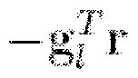 wherein the design cost function:
' J = I where the vector 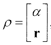 contains all the variables and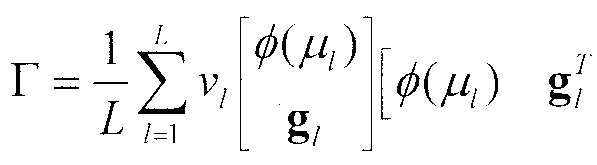
wherein determining T comprising mint subject to r11P <t
'.P
TGo) >0.
16. The method according to claim 15, wherein determining T is subject to
Tmm(p) = — , m = 1, ... , M M
17. The method according to claim 15, wherein determining T is subject to tr(T) = c .
18. The method according to claim 15, further comprising: applying the constraint a*i/// iTaψj ) — g. / — 1 , ■ ■ - , /.., where {ζ,} are the prescribed values and {μt) are the corresponding mesh grids.
19. The method according to claim 15, further comprising: applying the constraint  for some h ≠ j, where μk and μ are the locations at which equal gain or certain ratio is desired.
20. The method according to claim 1, further comprising: applying the constraint min - t
T subject to a (O0)Ta(O0) -a (μp)Ta(μP) > t, /^ e T1 ,
T > 0 , wherein the main-beam is directed toward O0 , where the sidelobe region is Ψs .
21. The method according to claim 20, further comprising: applying the constraint 0 < a*(6l 0)Ta(6'0) -a*(///7)Ta(///,) < 0.5a*(00)Ta(00), μp e Ψm
wherein the 3-dB main-beam region is Ψ m .
22. The method according to claim 20, further comprising: applying the constraint 0.5a*(6'0)Ta(6'0) - a'k(6';)Ta(6',) = 0, / = 1,2, wherein the prescribed 3-dB angles are θλ and θ2 (the 3-dB beamwidth is O1 - Ox , with O2 > O0 and O1 < O0 ).
23. The method according to claim 20, further comprising:
applying the constraint Tmm } m = \, ... , M.
M '
24. The method according to claim 20, further comprising: applying the constraint tr(T) — c .
25. The method according to claim 5, further comprising: outputting an output signal vector W y(n) n=l , ... . N.
26. The method according to claim 25, wherein the output signal vector is utilized in radar.
27. The method according to claim 25, wherein the output signal vector is utilized in sonar.
28. The method according to claim 25. wherein the output signal vector is utilized in aeroacoustics.
29. The method according to claim 25, wherein the output signal vector is utilized in communications.
30. The method according to claim 25, wherein the output signal vector is utilized in medical imaging.
31. The method according to claim 5, further comprising: outputting an estimate of the signal s(n) = w*y(«) . where W has rank-1 and is denoted as w.
Applications Claiming Priority (2)
| Application Number | Priority Date | Filing Date | Title |
|---|---|---|---|
| US83394806P | 2006-07-28 | 2006-07-28 | |
| US60/833,948 | 2006-07-28 |
Publications (1)
| Publication Number | Publication Date |
|---|---|
| WO2008105909A2 true WO2008105909A2 (en) | 2008-09-04 |
Family
ID=39660430
Family Applications (1)
| Application Number | Title | Priority Date | Filing Date |
|---|---|---|---|
| PCT/US2007/074739 Ceased WO2008105909A2 (en) | 2006-07-28 | 2007-07-30 | Optimal beam pattern synthesis via matrix weighting |
Country Status (1)
| Country | Link |
|---|---|
| WO (1) | WO2008105909A2 (en) |
Cited By (11)
| Publication number | Priority date | Publication date | Assignee | Title |
|---|---|---|---|---|
| DE102012008085A1 (en) * | 2012-04-20 | 2013-10-24 | Atlas Elektronik Gmbh | Method and device for spatially filtering sound waves |
| CN103760529A (en) * | 2013-12-06 | 2014-04-30 | 河海大学 | Efficient cascading space-time adaptive processing method based on passive detection |
| CN106126836A (en) * | 2016-06-28 | 2016-11-16 | 西安电子科技大学 | Array aerial direction figure approximating method based on the weighting normal direction Return Law |
| CN109061561A (en) * | 2018-08-09 | 2018-12-21 | 西北工业大学 | A kind of adaptive array Pattern Synthesis method based on binary chop |
| CN111224704A (en) * | 2019-11-12 | 2020-06-02 | 电子科技大学 | Distributed self-adaptive reduced rank beam forming method |
| CN111257891A (en) * | 2020-02-08 | 2020-06-09 | 西北工业大学 | A Deconvolution-Based Method for MIMO Sonar Range Sidelobe Suppression |
| CN112130139A (en) * | 2020-08-21 | 2020-12-25 | 西安空间无线电技术研究所 | Distributed full-coherent sparse linear array radar system optimization array arrangement method |
| US20210184350A1 (en) * | 2019-12-12 | 2021-06-17 | Mano D. Judd | Passive beam mechanics to reduce grating lobes |
| DE102021118403A1 (en) | 2021-07-16 | 2023-01-19 | ELAC SONAR GmbH | Method and device for adaptive beamforming |
| CN115832721A (en) * | 2022-11-29 | 2023-03-21 | 中国科学院声学研究所 | A sparse linear array design method and device |
| CN119807620A (en) * | 2024-12-20 | 2025-04-11 | 西北工业大学 | A constant beamwidth beamforming method based on vector combination array |
-
2007
- 2007-07-30 WO PCT/US2007/074739 patent/WO2008105909A2/en not_active Ceased
Cited By (17)
| Publication number | Priority date | Publication date | Assignee | Title |
|---|---|---|---|---|
| DE102012008085B4 (en) * | 2012-04-20 | 2013-11-07 | Atlas Elektronik Gmbh | Method and device for spatially filtering sound waves |
| DE102012008085A1 (en) * | 2012-04-20 | 2013-10-24 | Atlas Elektronik Gmbh | Method and device for spatially filtering sound waves |
| CN103760529A (en) * | 2013-12-06 | 2014-04-30 | 河海大学 | Efficient cascading space-time adaptive processing method based on passive detection |
| CN106126836A (en) * | 2016-06-28 | 2016-11-16 | 西安电子科技大学 | Array aerial direction figure approximating method based on the weighting normal direction Return Law |
| CN106126836B (en) * | 2016-06-28 | 2019-05-10 | 西安电子科技大学 | Array Antenna Pattern Fitting Method Based on Weighted Normal Regression |
| CN109061561A (en) * | 2018-08-09 | 2018-12-21 | 西北工业大学 | A kind of adaptive array Pattern Synthesis method based on binary chop |
| CN111224704B (en) * | 2019-11-12 | 2022-10-11 | 电子科技大学 | Distributed self-adaptive reduced rank beam forming method |
| CN111224704A (en) * | 2019-11-12 | 2020-06-02 | 电子科技大学 | Distributed self-adaptive reduced rank beam forming method |
| US20210184350A1 (en) * | 2019-12-12 | 2021-06-17 | Mano D. Judd | Passive beam mechanics to reduce grating lobes |
| CN111257891A (en) * | 2020-02-08 | 2020-06-09 | 西北工业大学 | A Deconvolution-Based Method for MIMO Sonar Range Sidelobe Suppression |
| CN111257891B (en) * | 2020-02-08 | 2022-07-26 | 西北工业大学 | Deconvolution-based MIMO sonar distance sidelobe suppression method |
| CN112130139A (en) * | 2020-08-21 | 2020-12-25 | 西安空间无线电技术研究所 | Distributed full-coherent sparse linear array radar system optimization array arrangement method |
| CN112130139B (en) * | 2020-08-21 | 2024-05-03 | 西安空间无线电技术研究所 | Distributed full-coherent sparse linear array radar system optimization array deployment method |
| DE102021118403A1 (en) | 2021-07-16 | 2023-01-19 | ELAC SONAR GmbH | Method and device for adaptive beamforming |
| DE102021118403B4 (en) | 2021-07-16 | 2024-01-18 | ELAC SONAR GmbH | Method and device for adaptive beamforming |
| CN115832721A (en) * | 2022-11-29 | 2023-03-21 | 中国科学院声学研究所 | A sparse linear array design method and device |
| CN119807620A (en) * | 2024-12-20 | 2025-04-11 | 西北工业大学 | A constant beamwidth beamforming method based on vector combination array |
Similar Documents
| Publication | Publication Date | Title |
|---|---|---|
| WO2008105909A2 (en) | Optimal beam pattern synthesis via matrix weighting | |
| Li et al. | Doubly constrained robust Capon beamformer | |
| Shahbazpanahi et al. | Robust adaptive beamforming for general-rank signal models | |
| Rafaely et al. | Spherical microphone array beamforming | |
| CN110113085B (en) | Wave beam forming method and system based on covariance matrix reconstruction | |
| Varade et al. | Robust algorithms for DOA estimation and adaptive beamforming for smart antenna application | |
| Qian et al. | Null broadening adaptive beamforming based on covariance matrix reconstruction and similarity constraint | |
| Li et al. | Beampattern synthesis via a matrix approach for signal power estimation | |
| CN105162528A (en) | Anti-interference method and apparatus based on satellite communication phased-array antenna | |
| Sun et al. | Robust minimum sidelobe beamforming for spherical microphone arrays | |
| Wang et al. | Design of optimum sparse array for robust MVDR beamforming against DOA mismatch | |
| Wang et al. | A general superdirectivity model for arbitrary sensor arrays | |
| Wang et al. | High-order superdirectivity of circular sensor arrays mounted on baffles | |
| Hossain et al. | Robust efficient broadband antenna array pattern synthesis techniques | |
| Abhayapala | Modal analysis and synthesis of broadband nearfield beamforming arrays | |
| Hamza et al. | Optimum sparse array design for maximizing signal-to-noise ratio in presence of local scatterings | |
| Pal et al. | Frequency invariant MVDR beamforming without filters and implementation using MIMO radar | |
| Chen et al. | Direction-of-arrival estimation of coherent narrowband signals with arbitrary linear array | |
| Nechaev et al. | The Research of the Digital Beamforming Algorithm for Optimal Noise Reduction in a Cylindrical Antenna Array with Directive Radiators | |
| Liu et al. | A virtual space-time adaptive beamforming method for space-time antijamming | |
| Friedlander et al. | Adaptive signal design for MIMO radars | |
| Li et al. | A null broadening beamforming method of virtual antenna array | |
| Xu et al. | Robust beamforming method for coprime array with accurate covariance matrix reconstruction | |
| Erdim et al. | Mitigating interferers with a universal beamformer that hybridizes adaptive and conventional beamformers | |
| Ulrey et al. | Optimum element distribution for circular adaptive antenna systems |
Legal Events
| Date | Code | Title | Description |
|---|---|---|---|
| 121 | Ep: the epo has been informed by wipo that ep was designated in this application |
Ref document number: 07873744 Country of ref document: EP Kind code of ref document: A2 |
|
| NENP | Non-entry into the national phase in: |
Ref country code: DE |
|
| NENP | Non-entry into the national phase in: |
Ref country code: RU |
|
| 122 | Ep: pct app. not ent. europ. phase |
Ref document number: 07873744 Country of ref document: EP Kind code of ref document: A2 |