WO2008016397A1 - Diversity switching - Google Patents
Diversity switching Download PDFInfo
- Publication number
- WO2008016397A1 WO2008016397A1 PCT/US2007/006259 US2007006259W WO2008016397A1 WO 2008016397 A1 WO2008016397 A1 WO 2008016397A1 US 2007006259 W US2007006259 W US 2007006259W WO 2008016397 A1 WO2008016397 A1 WO 2008016397A1
- Authority
- WO
- WIPO (PCT)
- Prior art keywords
- antenna
- received
- antennas
- pair
- switch
- Prior art date
Links
Classifications
-
- H—ELECTRICITY
- H04—ELECTRIC COMMUNICATION TECHNIQUE
- H04B—TRANSMISSION
- H04B7/00—Radio transmission systems, i.e. using radiation field
- H04B7/02—Diversity systems; Multi-antenna system, i.e. transmission or reception using multiple antennas
- H04B7/04—Diversity systems; Multi-antenna system, i.e. transmission or reception using multiple antennas using two or more spaced independent antennas
- H04B7/08—Diversity systems; Multi-antenna system, i.e. transmission or reception using multiple antennas using two or more spaced independent antennas at the receiving station
- H04B7/0802—Diversity systems; Multi-antenna system, i.e. transmission or reception using multiple antennas using two or more spaced independent antennas at the receiving station using antenna selection
- H04B7/0817—Diversity systems; Multi-antenna system, i.e. transmission or reception using multiple antennas using two or more spaced independent antennas at the receiving station using antenna selection with multiple receivers and antenna path selection
- H04B7/082—Diversity systems; Multi-antenna system, i.e. transmission or reception using multiple antennas using two or more spaced independent antennas at the receiving station using antenna selection with multiple receivers and antenna path selection selecting best antenna path
-
- H—ELECTRICITY
- H04—ELECTRIC COMMUNICATION TECHNIQUE
- H04B—TRANSMISSION
- H04B7/00—Radio transmission systems, i.e. using radiation field
- H04B7/02—Diversity systems; Multi-antenna system, i.e. transmission or reception using multiple antennas
- H04B7/04—Diversity systems; Multi-antenna system, i.e. transmission or reception using multiple antennas using two or more spaced independent antennas
- H04B7/08—Diversity systems; Multi-antenna system, i.e. transmission or reception using multiple antennas using two or more spaced independent antennas at the receiving station
- H04B7/0802—Diversity systems; Multi-antenna system, i.e. transmission or reception using multiple antennas using two or more spaced independent antennas at the receiving station using antenna selection
- H04B7/0805—Diversity systems; Multi-antenna system, i.e. transmission or reception using multiple antennas using two or more spaced independent antennas at the receiving station using antenna selection with single receiver and antenna switching
- H04B7/0808—Diversity systems; Multi-antenna system, i.e. transmission or reception using multiple antennas using two or more spaced independent antennas at the receiving station using antenna selection with single receiver and antenna switching comparing all antennas before reception
- H04B7/0811—Diversity systems; Multi-antenna system, i.e. transmission or reception using multiple antennas using two or more spaced independent antennas at the receiving station using antenna selection with single receiver and antenna switching comparing all antennas before reception during preamble or gap period
Definitions
- Diversity reception schemes may be used to improve the quality of wireless communications. While there are various types of diversity reception schemes known, one of them involves the use of multiple antennas. While multiple antennas may be used in various ways, a particular way in which they may be used is in a switching scheme, in which the output of a particular receive antenna may be routed to a particular receiver chain. This type of scheme may be referred to as switched diversity. In some switched diversity schemes, which antenna output is routed to a receiver chain may be determined based on a signal-to-noise ratio (SNR) determined for each antenna. However, SNR determination may be computationally intensive, and SNR approximations may be inaccurate and may thus lead to less than reliable results.
- SNR signal-to-noise ratio
- RSSI received signal strength indicator
- Figure 1 is a conceptual block diagram of a system in which various embodiments of the invention may be used;
- Figure 2 shows a conceptual diagram of a preamble structure that may be used in various embodiments of the invention;
- Figure 3 shows a timing diagram of how switching criteria may be evaluated in some embodiments of the invention
- Figures 4A, 4B, and 4C show flowcharts of exemplary embodiments of the invention, which may be based on the preamble structures shown in Figures 2 and 3;
- Figure 5 shows a flowchart of a further exemplary embodiment of the invention
- Figure 6 shows how switching criteria may be evaluated according to some embodiments of the invention
- Figure 7 shows an exemplary block diagram showing an expanded embodiment of the invention.
- Figure 8 shows a schematic block diagram of an apparatus that may be used in implementing various exemplary embodiments of the invention.
- references to "one embodiment”, “an embodiment”, “example embodiment”, “various embodiments”, etc., indicate that the embodiment(s) of the invention so described may include a particular feature, structure, or characteristic, but not every embodiment necessarily includes the particular feature, structure, or characteristic. Further, repeated use of the phrase “in one embodiment” or “in an embodiment” does not necessarily refer to the same embodiment, although it may.
- Coupled may mean that two or more elements are in direct physical or electrical contact with each other or that the two or more elements are not in direct contact but still cooperate or interact with each other.
- An algorithm is here, and generally, considered to be a self-consistent sequence of acts or operations leading to a desired result. These include physical manipulations of physical quantities. Usually, though not necessarily, these quantities take the form of electrical or magnetic signals capable of being stored, transferred, combined, compared, and otherwise manipulated. It has proven convenient at times, principally for reasons of common usage, to refer to these signals as bits, values, elements, symbols, characters, terms, numbers or the like. It should be understood, however, that all of these and similar terms are to be associated with the appropriate physical quantities and are merely convenient labels applied to these quantities.
- processor may refer to any device or portion of a device that processes electronic data from registers and/or memory to transform that electronic data into other electronic data that may be stored in registers and/or memory.
- a “computing platform” may comprise one or more processors.
- Embodiments of the present invention may include apparatuses for performing the operations herein.
- An apparatus may be specially constructed for the desired purposes, or it may comprise a general purpose device selectively activated or reconfigured by a program stored in the device.
- Embodiments of the invention may be implemented in one or a combination of hardware, firmware, and software. Embodiments of the invention may also be implemented as instructions stored on a machine-readable medium, which may be read and executed by a computing platform to perform the operations described herein.
- a machine-readable medium may include any mechanism for storing or transmitting information in a form readable by a machine (e.g., a computer).
- a machine- readable medium may include machine-readable storage media, such as read only memory (ROM), random access memory (RAM), magnetic disk storage media, optical storage media, flash memory devices, and others, as well as electrical, optical, acoustical or other form of propagated signals (e.g., carrier waves, infrared signals, digital signals, etc.), and others.
- ROM read only memory
- RAM random access memory
- magnetic disk storage media such as magnetic disks, optical storage media, flash memory devices, and others
- electrical, optical, acoustical or other form of propagated signals e.g., carrier waves, infrared signals, digital signals, etc.
- a machine-readable storage medium may be located locally or remotely, with respect to other portions of embodiments of the invention (for example, but not limited to, a machine-readable medium accessed by means of a communication network).
- Figure 1 shows a switched diversity system that may be used in some embodiments of the invention.
- Figure 1 includes three antennas, 1 Ia, 1 Ib, and 1 Ic; however, there may be as few as two or more than three in some embodiments of the invention.
- Each of antennas 1 Ia-I Ic may be any antenna appropriate for receiving the signals to be received and may include, but are not limited to, directive antennas, phased arrays, monopoles, dipoles, etc.
- Antennas 1 Ia-I Ic may be coupled to receive apparatus 12.
- Receive apparatus 12 is shown as a single block in Figure 1, but it is not thus limited; on the contrary, receive apparatus 12 may include multiple components, some of which may be duplicative of one another.
- Receive apparatus 12 includes at least one receiver chain 13 (one is shown, but more may be present).
- Receiver chain 13 may include apparatus to process signals received from one or more of antennas 1 Ia-I Ic.
- each receiver chain 13 may be coupled to the outputs of the various antennas by means of a switching mechanism 14.
- switching mechanism 14 permits the coupling of an output from each of antennas 1 Ia-I Ic to receiver chain 13; however, the invention is not to be understood as being thus limited, and switching mechanism 14 may generally permit coupling of a given receiver chain 13 to only a subset of the outputs of antennas 1 Ia-I Ic.
- a switched diversity scheme may work in several ways, which may, for example, depend upon the type and/or quantity of processing facilities. As noted above, in a switched diversity scheme, some quantity indicative of the quality of a signal being received by an antenna 1 Ia-I Ic may be determined and used to determine which antenna to couple to a receiver chain 13. The determination of signal quality may be performed by appropriate apparatus associated with each antenna, or the signals from the various antennas may be switched among one or more such apparatuses. Furthermore, the determination of signal quality may be based on analog and/or digital methods.
- a preamble may be included as a first portion of a transmission. Such a preamble may be used to determine signal quality for purposes of diversity switching, prior to processing data content of a transmitted signal.
- Figure 2 shows an exemplary preamble format and how it may fit into an overall signaling format.
- a frame may include downlink (DL) and uplink (UL) subframes.
- the DL subframe may include, among other portions, a "Long Preamble;" an example of where this structure may be found is in some of the standards for use in short-range wireless signaling.
- the Long Preamble may, in turn, include a cyclic prefix (CP), followed by four 64-sample preamble portions, which may be followed by another CP portion and another two 128-sample preamble portions.
- CP cyclic prefix
- 64-sample preamble portions which may be followed by another CP portion and another two 128-sample preamble portions.
- all of these preamble portions are shown as occurring prior to the transmission of downlink data transmissions ( 11 DL Bursts").
- the receive apparatus 12 may have only a single apparatus, which may be part of or separate from receiver chain 13, for evaluating signal quality from the antennas 1 Ia-I Ic.
- the single apparatus may be shared among all of the antennas 1 Ia-I Ic.
- Figure 3 shows one way in which this may be done, according to some embodiments of the invention.
- a first interval denoted "00"
- the output of a first antenna may be evaluated, based on a first portion of the preamble.
- this first portion may comprise the first two 64-sample preamble portions as shown in Figure 2.
- a second antenna may be evaluated using a second portion of the preamble, which may correspond to the second two 64-sample preamble portions as shown in Figure 2; however, the invention is not thus limited.
- a third antenna if present, may, for example, be evaluated using the portion denoted "10" in Figure 3, which may correspond to one or more of the 128-sample portions of the preamble structure as shown in Figure 2, but to which the invention is not limited.
- SNR signal-to-noise ratio
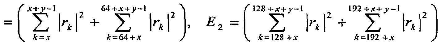
- ⁇ r k ⁇ TM ⁇ l represents the data of the four 64-sample exemplary preamble portions shown in Figures 2 and 3.
- a block of y-samples may be represented ⁇ r k ⁇ x ⁇ J' ⁇ l (and similarly for subsequent blocks by adding 64 to the limits each time).
- x is used to denote a predetermined beginning sample number
- y is used to denote a total block size.
- x may equal 0, and y may equal 64.
- not all of the samples may be used in determining the various quantities in all cases. It is further noted that, if there is more than one apparatus for evaluating signal quality, more than one antenna may be analyzed during a single interval. Therefore, a common block of samples may be used to evaluate the signal quality for more than one antenna.
- FIG. 4A A flowchart of the case of two antennas, corresponding to this formulation is shown in Figure 4A, according to an exemplary embodiment of the invention. It is noted that if there are an arbitrary number of antennas, the formulation of the problem in terms of SNRs would involve pair-wise comparisons of the SNRs of the various antennas. Similarly, as may be shown by forming the corresponding inequalities and cross-multiplying and squaring, pair-wise determination and comparisons of quality factors may be used in the alternative formulation of the problem. For example, the flowchart of Figure 4B shows how the flowchart of Figure 4A may be expanded to accommodate a third antenna, according to an exemplary embodiment of the invention.
- Figure 4C shows an exemplary embodiment in which four antennas may be compared.
- two preambles may be used to accommodate the four antennas, as shown (again, this may correspond to the case in which there is only a single module capable of computing the various quantities at a given time, and which, therefore, may be switched among the four antennas; if there are multiple modules, it may be possible to compute the quantities for multiple antennas at the same time).
- a CQF may be defined as any quantity, based on signals received at two antennas, on which the relative signal qualities at those two antennas may be based.
- another CQF may be computed as P 4 >r -P n ⁇ , for use in comparing the signals received by the i th and j th antennas (in other words, P 3 1 -P n 7 may be compared to P ⁇ j -P n , to determine which signal has the better quality).
- This formulation of the CQF is reflected in the flowchart shown in Figure 5 (it is noted that the CQFs used in Figure 5 are denoted "QFV' and "QF' 2 " to differentiate them from the QFs of the previous figures).
- This formulation may, in turn, be generalized to be based on any equivalent measurements (or derivatives of such measurements, for example, but not limited to, the square of the above SNR formulation, i.e., using the signal power squared and the noise power squared), which may be (or be based on) either analog measurements or digital measurements, and which may be based on discrete-time signals or continuous-time signals (or as combinations of any of these types of measurements and signals). That is, while the QF given above may be determined based on signal samples, the invention is not to be understood as being thus limited. Furthermore, while the discussion below focuses on the case of the QF, the discussion below may also be generalized in the fashion discussed above to apply to the CQF.
- FIG. 6 shows a conceptual diagram of this, based on the embodiment of Figure 3.
- a number of samples, "x”, may be excluded to account for switching ripple effects, while a number of samples, "z", may be excluded to account for switching latency.
- the quantities discussed above may still be determined using the equations above, but now x may be non-zero, and, for the example of 64-sample preamble portions, y may equal 64-z. For example, if a first 64-sample interval were to be considered, starting with the first (0 th ) sample, the upper and lower limits of the first summation to determine Ei may be x and x+64-z-l, respectively.
- the sum of x and z may be relatively large in comparison with the number of samples in a preamble portion that may be used to determine QF.
- the quantities computed may not be sufficiently meaningful (statistically significant) to accurately reflect the relative signal qualities.
- one may use more samples.
- all four 64-sample portions which may be divided into two 128-sample portions, may be used, along with the two 128- sample portions.
- the first 256-sample portion i.e., four 64-sample portions
- the second 256-sample portion i.e., two 128- sample portions
- two different preambles may be used to compute the necessary quantities.
- various embodiments of the invention may include more than one receiver chain 13, say N receiver chains 13a-13b, as shown in the exemplary block diagram of Figure 7.
- the above methods may be adapted in straightforward fashion to select the N out of M antennas 1 Ia-I Ic having the highest quality factors, in pair-wise comparisons. That is, as above, the quality factors may be determined for each pair of antennas 1 Ia-I Ic, and the antennas having the highest quality factors, relative to one another, may be selected to be connected to receiver chains 13a- 13b.
- filtered switched diversity statistics may be used to determine which antenna(s) to connect to the receiver chain(s).
- ⁇ is a filter parameter, which may be predetermined, set by the user, or set by the system designer.
- other filters may be used.
- the computer system of Figure 8 may include at least one processor 82, with associated system memory 81, which may store, for example, operating system software and the like.
- the system may further include other additional memory 83, which may, for example, include software instructions to perform various applications.
- System memory 81 and other memory 83 may comprise separate memory devices, a single shared memory device, or a combination of separate and shared memory devices.
- the system may also include one or more input/output (I/O) devices 84, for example (but not limited to), keyboard, mouse, trackball, printer, display, network connection, etc.
- I/O input/output
- the present invention may be embodied as software instructions that may be stored in system memory 81 or in other memory 83. Such software instructions may also be stored in removable or remote storage media (for example, but not limited to, compact disks, floppy disks, etc.), which may be read through an I/O device 84 (for example, but not limited to, a floppy disk drive). Furthermore, the software instructions may also be transmitted to the computer system via an I/O device 84, for example, a network connection; in such a case, a signal containing the software instructions may be considered to be a machine-accessible medium.
- I/O device 84 for example, a network connection
Abstract
A comparative quality factor may be based on quantities indicative of signal and noise received at multiple antennas and may be used to control switching in a switched diversity system.
Description
DIVERSITY SWITCHING
BACKGROUND OF THE INVENTION
Diversity reception schemes may be used to improve the quality of wireless communications. While there are various types of diversity reception schemes known, one of them involves the use of multiple antennas. While multiple antennas may be used in various ways, a particular way in which they may be used is in a switching scheme, in which the output of a particular receive antenna may be routed to a particular receiver chain. This type of scheme may be referred to as switched diversity. In some switched diversity schemes, which antenna output is routed to a receiver chain may be determined based on a signal-to-noise ratio (SNR) determined for each antenna. However, SNR determination may be computationally intensive, and SNR approximations may be inaccurate and may thus lead to less than reliable results.
In other switched diversity schemes, a received signal strength indicator (RSSI) may be used for determining which antenna output is routed to a receiver chain. While RSSI determination may be less computationally intensive than SNR determination, switching based on RSSI, only, may also be less than reliable.
BRIEF DESCRIPTION OF THE DRAWINGS Various embodiments of the invention may be better understood by reading the following detailed description with reference to the accompanying figures, in which like reference numerals refer to like elements throughout, and in which:
Figure 1 is a conceptual block diagram of a system in which various embodiments of the invention may be used; Figure 2 shows a conceptual diagram of a preamble structure that may be used in various embodiments of the invention;
Figure 3 shows a timing diagram of how switching criteria may be evaluated in some embodiments of the invention;
Figures 4A, 4B, and 4C show flowcharts of exemplary embodiments of the invention, which may be based on the preamble structures shown in Figures 2 and 3;
Figure 5 shows a flowchart of a further exemplary embodiment of the invention; Figure 6 shows how switching criteria may be evaluated according to some
embodiments of the invention;
Figure 7 shows an exemplary block diagram showing an expanded embodiment of the invention; and
Figure 8 shows a schematic block diagram of an apparatus that may be used in implementing various exemplary embodiments of the invention.
DETAILED DESCRIPTION OF VARIOUS EMBODIMENTS
In the following description, numerous specific details are set forth. However, it is understood that embodiments of the invention may be practiced without these specific details. In other instances, well-known circuits, structures, and/or techniques have not been shown in detail in order not to obscure an understanding of this description.
References to "one embodiment", "an embodiment", "example embodiment", "various embodiments", etc., indicate that the embodiment(s) of the invention so described may include a particular feature, structure, or characteristic, but not every embodiment necessarily includes the particular feature, structure, or characteristic. Further, repeated use of the phrase "in one embodiment" or "in an embodiment" does not necessarily refer to the same embodiment, although it may.
In the following description and claims, the term "coupled," along with its derivatives, may be used. It should be understood that "coupled" may mean that two or more elements are in direct physical or electrical contact with each other or that the two or more elements are not in direct contact but still cooperate or interact with each other.
An algorithm is here, and generally, considered to be a self-consistent sequence of acts or operations leading to a desired result. These include physical manipulations of physical quantities. Usually, though not necessarily, these quantities take the form of electrical or magnetic signals capable of being stored, transferred, combined, compared, and otherwise manipulated. It has proven convenient at times, principally for reasons of common usage, to refer to these signals as bits, values, elements, symbols, characters, terms, numbers or the like. It should be understood, however, that all of these and similar terms are to be associated with the appropriate physical quantities and are merely convenient labels applied to these quantities.
Unless specifically stated otherwise, as apparent from the following discussions, it
is appreciated that throughout the specification discussions utilizing terms such as "processing," "computing," "calculating," "determining," or the like, refer to the action and/or processes of a computer or computing system, or similar electronic computing device, that manipulate and/or transform data represented as physical, such as electronic, quantities within the computing system's registers and/or memories into other data similarly represented as physical quantities within the computing system's memories, registers or other such information storage, transmission or display devices.
In a similar manner, the term "processor" may refer to any device or portion of a device that processes electronic data from registers and/or memory to transform that electronic data into other electronic data that may be stored in registers and/or memory. A "computing platform" may comprise one or more processors.
Embodiments of the present invention may include apparatuses for performing the operations herein. An apparatus may be specially constructed for the desired purposes, or it may comprise a general purpose device selectively activated or reconfigured by a program stored in the device.
Embodiments of the invention may be implemented in one or a combination of hardware, firmware, and software. Embodiments of the invention may also be implemented as instructions stored on a machine-readable medium, which may be read and executed by a computing platform to perform the operations described herein. A machine-readable medium may include any mechanism for storing or transmitting information in a form readable by a machine (e.g., a computer). For example, a machine- readable medium may include machine-readable storage media, such as read only memory (ROM), random access memory (RAM), magnetic disk storage media, optical storage media, flash memory devices, and others, as well as electrical, optical, acoustical or other form of propagated signals (e.g., carrier waves, infrared signals, digital signals, etc.), and others. A machine-readable storage medium may be located locally or remotely, with respect to other portions of embodiments of the invention (for example, but not limited to, a machine-readable medium accessed by means of a communication network).
Figure 1 shows a switched diversity system that may be used in some embodiments of the invention. Figure 1 includes three antennas, 1 Ia, 1 Ib, and 1 Ic; however, there may be as few as two or more than three in some embodiments of the invention. Each of antennas 1 Ia-I Ic may be any antenna appropriate for receiving the signals to be received
and may include, but are not limited to, directive antennas, phased arrays, monopoles, dipoles, etc. Antennas 1 Ia-I Ic may be coupled to receive apparatus 12. Receive apparatus 12 is shown as a single block in Figure 1, but it is not thus limited; on the contrary, receive apparatus 12 may include multiple components, some of which may be duplicative of one another. Receive apparatus 12 includes at least one receiver chain 13 (one is shown, but more may be present). Receiver chain 13 may include apparatus to process signals received from one or more of antennas 1 Ia-I Ic. In a switched diversity system, each receiver chain 13 may be coupled to the outputs of the various antennas by means of a switching mechanism 14. As shown in Figure 1, switching mechanism 14 permits the coupling of an output from each of antennas 1 Ia-I Ic to receiver chain 13; however, the invention is not to be understood as being thus limited, and switching mechanism 14 may generally permit coupling of a given receiver chain 13 to only a subset of the outputs of antennas 1 Ia-I Ic.
A switched diversity scheme may work in several ways, which may, for example, depend upon the type and/or quantity of processing facilities. As noted above, in a switched diversity scheme, some quantity indicative of the quality of a signal being received by an antenna 1 Ia-I Ic may be determined and used to determine which antenna to couple to a receiver chain 13. The determination of signal quality may be performed by appropriate apparatus associated with each antenna, or the signals from the various antennas may be switched among one or more such apparatuses. Furthermore, the determination of signal quality may be based on analog and/or digital methods.
In many communication systems, a preamble may be included as a first portion of a transmission. Such a preamble may be used to determine signal quality for purposes of diversity switching, prior to processing data content of a transmitted signal. Figure 2 shows an exemplary preamble format and how it may fit into an overall signaling format.
In particular, a frame may include downlink (DL) and uplink (UL) subframes. The DL subframe may include, among other portions, a "Long Preamble;" an example of where this structure may be found is in some of the standards for use in short-range wireless signaling. As shown, the Long Preamble may, in turn, include a cyclic prefix (CP), followed by four 64-sample preamble portions, which may be followed by another CP portion and another two 128-sample preamble portions. In Figure 2, all of these preamble portions are shown as occurring prior to the transmission of downlink data transmissions
(11DL Bursts").
In one embodiment of the invention, as mentioned above, the receive apparatus 12 may have only a single apparatus, which may be part of or separate from receiver chain 13, for evaluating signal quality from the antennas 1 Ia-I Ic. In that case, the single apparatus may be shared among all of the antennas 1 Ia-I Ic. Figure 3 shows one way in which this may be done, according to some embodiments of the invention. In a first interval, denoted "00", the output of a first antenna may be evaluated, based on a first portion of the preamble. In some embodiments, to which the invention is not limited, this first portion may comprise the first two 64-sample preamble portions as shown in Figure 2. Similarly, a second antenna, denoted "01", may be evaluated using a second portion of the preamble, which may correspond to the second two 64-sample preamble portions as shown in Figure 2; however, the invention is not thus limited. A third antenna, if present, may, for example, be evaluated using the portion denoted "10" in Figure 3, which may correspond to one or more of the 128-sample portions of the preamble structure as shown in Figure 2, but to which the invention is not limited.
One way to determine an antenna to use would be to compute a signal-to-noise ratio (SNR) for each antenna and to compare the SNRs for the different antennas. In general, SNR may be represented as:
SNRk = -= — ΓΓΓT , where "X" represents signal energy, while "E" represents the total received energy (signal plus noise). The subscript "k" is used to denote the kth antenna. For the exemplary case discussed above, in which there is a single apparatus for determining the signal quality for all of the antennas, the various quantities may be computed, in general, as follows:
 π J and
( x + y-l "\ / 128 +*+>>- 1 λ
∑ rk rk+<» > Xz = ∑ rk r* +64 , Jc = X J V * = 128 +.ϊ J where {rk }™~l represents the data of the four 64-sample exemplary preamble portions shown in Figures 2 and 3. Given this, a block of y-samples may be represented {rk }x^J'~l (and similarly for subsequent blocks by adding 64 to the limits each time). Here "x" is
used to denote a predetermined beginning sample number, and "y" is used to denote a total block size. For example, if all of the samples of a 64-sample block were used, x may equal 0, and y may equal 64. As will be discussed below, in some embodiments, not all of the samples may be used in determining the various quantities in all cases. It is further noted that, if there is more than one apparatus for evaluating signal quality, more than one antenna may be analyzed during a single interval. Therefore, a common block of samples may be used to evaluate the signal quality for more than one antenna.
In the case of a pair of antennas (k=l,2), one may decide to use antenna 1 if SNR|>SNR2 or antenna 2 if SNR2>SNRi. Given this, and cross-multiplying from the SNR equation above (and squaring both sides), results in the following alternative formulation of the problem:
 , where XA,re is the real part of Xk and Xk im is the real part of X k for Ic=I, 2. QFk may be called the "quality factor" for the kth antenna. The first factor of the quality factor may be thought of as the square of a received signal strength indicator, while the second factor of the quality factor may be thought of as the square of total received energy. A flowchart of the case of two antennas, corresponding to this formulation is shown in Figure 4A, according to an exemplary embodiment of the invention. It is noted that if there are an arbitrary number of antennas, the formulation of the problem in terms of SNRs would involve pair-wise comparisons of the SNRs of the various antennas. Similarly, as may be shown by forming the corresponding inequalities and cross-multiplying and squaring, pair-wise determination and comparisons of quality factors may be used in the alternative formulation of the problem. For example, the flowchart of Figure 4B shows how the flowchart of Figure 4A may be expanded to accommodate a third antenna, according to an exemplary embodiment of the invention.
In yet a further exemplary expansion of the flowchart of Figure 4A, Figure 4C shows an exemplary embodiment in which four antennas may be compared. In the example of Figure 4C, two preambles may be used to accommodate the four antennas, as shown (again, this may correspond to the case in which there is only a single module capable of computing the various quantities at a given time, and which, therefore, may be switched among the four antennas; if there are multiple modules, it may be possible to
compute the quantities for multiple antennas at the same time). As shown in Figure 4C, there may be two layers of comparisons. A first layer may be used to compare two pairs of antennas, and the second layer may be used to compare the two antennas found to have the better qualities in the first layer of comparisons. It is noted that the above development may be further generalized. The QFk developed above is one example of what will be termed here a "comparative quality factor" (CQF). In general, a CQF may be defined as any quantity, based on signals received at two antennas, on which the relative signal qualities at those two antennas may be based. For example, SNR may be formulated in terms of signal power (P5) and noise p power (Pn) (i.e., as SNRk = — — , where the subscript k is used to denote the kth antenna.
Using this formulation, another CQF may be computed as P4 >r -Pn ^, for use in comparing the signals received by the ith and jth antennas (in other words, P3 1 -Pn 7 may be compared to P^j -Pn , to determine which signal has the better quality). This formulation of the CQF is reflected in the flowchart shown in Figure 5 (it is noted that the CQFs used in Figure 5 are denoted "QFV' and "QF'2" to differentiate them from the QFs of the previous figures). This formulation may, in turn, be generalized to be based on any equivalent measurements (or derivatives of such measurements, for example, but not limited to, the square of the above SNR formulation, i.e., using the signal power squared and the noise power squared), which may be (or be based on) either analog measurements or digital measurements, and which may be based on discrete-time signals or continuous-time signals (or as combinations of any of these types of measurements and signals). That is, while the QF given above may be determined based on signal samples, the invention is not to be understood as being thus limited. Furthermore, while the discussion below focuses on the case of the QF, the discussion below may also be generalized in the fashion discussed above to apply to the CQF.
When apparatus is switched between or among antennas, physical switches may cause latency (delay) and/or ripple effects. To avoid these, which may improve the accuracy of the calculations above, a few samples may be skipped at the beginning and/or at the end of each portion of the preamble. Figure 6 shows a conceptual diagram of this, based on the embodiment of Figure 3. In Figure 6, a number of samples, "x", may be excluded to account for switching ripple effects, while a number of samples, "z", may be
excluded to account for switching latency. In this embodiment, the quantities discussed above may still be determined using the equations above, but now x may be non-zero, and, for the example of 64-sample preamble portions, y may equal 64-z. For example, if a first 64-sample interval were to be considered, starting with the first (0th) sample, the upper and lower limits of the first summation to determine Ei may be x and x+64-z-l, respectively.
In some cases in which there may be large amounts of latency and/or ripple, the sum of x and z may be relatively large in comparison with the number of samples in a preamble portion that may be used to determine QF. For example, in the above example shown in Figure 2, to which the invention is not to be limited, if x+z is large with respect to 64, the quantities computed may not be sufficiently meaningful (statistically significant) to accurately reflect the relative signal qualities. In such a case, one may use more samples. For example, in the case shown in Figure 2, all four 64-sample portions, which may be divided into two 128-sample portions, may be used, along with the two 128- sample portions. In extreme cases, the first 256-sample portion (i.e., four 64-sample portions) may be used for switching, while the second 256-sample portion (i.e., two 128- sample portions) may be used for computing; in this case, for example, if there are two antennas and only one apparatus for determining QF, two different preambles may be used to compute the necessary quantities.
As noted above, various embodiments of the invention may include more than one receiver chain 13, say N receiver chains 13a-13b, as shown in the exemplary block diagram of Figure 7. In that case, if there are M antennas 1 Ia-I Ic, the above methods may be adapted in straightforward fashion to select the N out of M antennas 1 Ia-I Ic having the highest quality factors, in pair-wise comparisons. That is, as above, the quality factors may be determined for each pair of antennas 1 Ia-I Ic, and the antennas having the highest quality factors, relative to one another, may be selected to be connected to receiver chains 13a- 13b.
In some embodiments of the invention, filtered switched diversity statistics, over a number of frames or other time intervals, may be used to determine which antenna(s) to connect to the receiver chain(s). Such filtering may be, but is not limited to, a first-order moving average filter, such as: y(n) = a » x(n) + (1 - a) • y(n - 1) , where x(n) may represent the quality factor, e.g., for the nth frame, and where α is a filter
parameter, which may be predetermined, set by the user, or set by the system designer. As noted above, other filters may be used.
Some embodiments of the invention, as discussed above, may be embodied, at least in part, in the form of software instructions on a machine-accessible medium. Such an embodiment may be illustrated in Figure 8. The computer system of Figure 8 may include at least one processor 82, with associated system memory 81, which may store, for example, operating system software and the like. The system may further include other additional memory 83, which may, for example, include software instructions to perform various applications. System memory 81 and other memory 83 may comprise separate memory devices, a single shared memory device, or a combination of separate and shared memory devices. The system may also include one or more input/output (I/O) devices 84, for example (but not limited to), keyboard, mouse, trackball, printer, display, network connection, etc. The present invention, or parts thereof, may be embodied as software instructions that may be stored in system memory 81 or in other memory 83. Such software instructions may also be stored in removable or remote storage media (for example, but not limited to, compact disks, floppy disks, etc.), which may be read through an I/O device 84 (for example, but not limited to, a floppy disk drive). Furthermore, the software instructions may also be transmitted to the computer system via an I/O device 84, for example, a network connection; in such a case, a signal containing the software instructions may be considered to be a machine-accessible medium.
The embodiments illustrated and discussed in this specification are intended only to teach those skilled in the art the best way known to the inventors to make and use the invention. Nothing in this specification should be considered as limiting the scope of the present invention. The above-described embodiments of the invention may be modified or varied, and elements added or omitted, without departing from the invention, as appreciated by those skilled in the art in light of the above teachings. It is therefore to be understood that, within the scope of the claims and their equivalents, the invention may be practiced otherwise than as specifically described.
Claims
1. A method, comprising: determining, on a pair-wise basis, comparative quality factors corresponding to at least two antennas based on signals received by said at least two antennas; and selecting at least one of said signals to couple to at least one receiver chain based on said comparative quality factors.
2. The method according to Claim 1, wherein each said comparative quality factor is determined as a squared received signal strength indicator corresponding to a signal received by one antenna of a pair multiplied by a squared energy received by the other antenna of the pair.
3. The method according to Claim 1, wherein said determining comprises: computing said quality factors based on signals corresponding to at least one preamble portion of a received signal.
4. The method according to Claim 3, wherein said computing comprises: computing a squared received signal strength indicator and a squared energy received corresponding to different antennas based on different preamble portions.
5. The method according to Claim 3, wherein said computing comprises: omitting at least one portion of said signals of said at least one preamble corresponding to at least one of the time intervals selected from the group consisting of: a time interval corresponding to a switching latency time and a time interval corresponding to a switching ripple time.
6. The method according to Claim 1 , further comprising: prior to said selecting, filtering at least one of said comparative quality factors.
7. The method according to Claim 1 , wherein each said comparative quality factor is computed as a product of a quantity indicative of a quality of signal content received at one antenna of a pair multiplied by a quantity indicative of noise content received at the other antenna of the pair.
8. A machine-accessible medium containing software code that, when executed by a processor, causes the processor to execute the method comprising: determining, on a pair-wise basis, comparative quality factors corresponding to at least two antennas based on signals received by said at least two antennas; and selecting at least one of said signals to couple to at least one receiver chain based on said comparative quality factors.
9. The medium according to Claim 8, wherein each said comparative quality factor is determined as a squared received signal strength indicator corresponding to a signal received by one antenna of a pair multiplied by a squared energy received by the other antenna of the pair.
10. The machine-accessible medium according to Claim 8, wherein said determining comprises: computing said comparative quality factors based on signals corresponding to at least one preamble portion of a received signal.
1 1. The machine-accessible medium according to Claim 10, wherein said computing comprises: computing a squared received signal strength indicator and a squared energy received by different antennas based on different preamble portions.
12. The machine-accessible medium according to Claim 10, wherein said computing comprises: omitting at least one portion of said signals of said at least one preamble corresponding to at least one of the time intervals selected from the group consisting of: a time interval corresponding to a switching latency time and a time interval corresponding to a switching ripple time.
13. The machine-accessible medium according to Claim 8, further containing software code that, when executed by the processor, causes the processor to further execute: prior to said selecting, filtering at least one of said comparative quality factors.
14. The machine-accessible medium according to Claim 8, wherein each said comparative quality factor is computed as a product of a quantity indicative of a quality of signal content received at one antenna of a pair multiplied by a quantity indicative of noise content received at the other antenna of the pair.
15. An apparatus, comprising: at least one switch to switch among outputs of at least two antennas; at least one receiver chain, each receiver chain to be coupled to one of said at least one switch; and at least one module to determine, on a pair-wise basis, comparative quality factors corresponding to said at least two antennas based on signals received by said at least two antennas, the at least one module to be coupled to said at least one switch to control the at least one switch.
16. The apparatus according to Claim 15, wherein each said comparative quality factor is to be computed as a product of a quantity indicative of a quality of signal content received at one antenna of a pair multiplied by a quantity indicative of noise content received at the other antenna of the pair.
17. The apparatus according to Claim 16, wherein said quantity indicative of a quality of received signal content is to be determined as a squared received signal strength indicator, and wherein said quantity indicative of noise content is to be determined as a squared energy.
IS. The apparatus according to Claim 15, wherein said at least one module is a part of at least one receiver chain.
19. The apparatus according to Claim 15, wherein said at least one module comprises multiple modules, each to be coupled to an output of at least one antenna.
20. The apparatus according to Claim 19, wherein each said module is to be coupled to an output of at least one antenna via at least one said switch.
21. The apparatus according to Claim 15, wherein at least one said module includes: at least one filter to operate on at least one said comparative quality factor over more than one time interval.
22. A system, comprising: at least two antennas; at least one switch to switch among outputs of said at least two antennas; at least one receiver chain, each receiver chain to be coupled to one said switch; and at least one module to determine, on a pair-wise basis, comparative quality factors corresponding to said at least two antennas based on signals received by said at least two antennas, the at least one module to be coupled to said at least one switch to control the at least one switch.
23. The system according to Claim 22, wherein each said comparative quality factor is to be computed as a product of a quantity indicative of a quality of signal content received at one antenna of a pair multiplied by a quantity indicative of noise content received at the other antenna of the pair.
24. The system according to Claim 23, wherein said quantity indicative of a quality of received signal content is to be determined as a squared received signal strength indicator, and wherein said quantity indicative of noise content is to be determined as a squared energy.
25. The system according to Claim 22, wherein said at least one of said at least two antennas comprises an antenna selected from the group consisting of: a directive antenna; a monopole antenna, and a dipole antenna.
26. The system according to Claim 22, wherein said at least one module comprises multiple modules, each to be coupled to an output of at least one antenna via at least one said switch.
27. The system according to Claim 22, wherein at least one said module includes: at least one filter to operate on at least one said comparative quality factor over more than one time interval.
Priority Applications (2)
| Application Number | Priority Date | Filing Date | Title |
|---|---|---|---|
| KR1020097002058A KR101121253B1 (en) | 2006-08-02 | 2007-03-12 | Diversity switching |
| EP07752923A EP2050203A4 (en) | 2006-08-02 | 2007-03-12 | Diversity switching |
Applications Claiming Priority (2)
| Application Number | Priority Date | Filing Date | Title |
|---|---|---|---|
| US11/461,865 | 2006-08-02 | ||
| US11/461,865 US7706768B2 (en) | 2006-08-02 | 2006-08-02 | Diversity switching |
Publications (1)
| Publication Number | Publication Date |
|---|---|
| WO2008016397A1 true WO2008016397A1 (en) | 2008-02-07 |
Family
ID=38997462
Family Applications (1)
| Application Number | Title | Priority Date | Filing Date |
|---|---|---|---|
| PCT/US2007/006259 WO2008016397A1 (en) | 2006-08-02 | 2007-03-12 | Diversity switching |
Country Status (6)
| Country | Link |
|---|---|
| US (1) | US7706768B2 (en) |
| EP (1) | EP2050203A4 (en) |
| KR (1) | KR101121253B1 (en) |
| CN (1) | CN101127547B (en) |
| TW (1) | TWI360314B (en) |
| WO (1) | WO2008016397A1 (en) |
Families Citing this family (7)
| Publication number | Priority date | Publication date | Assignee | Title |
|---|---|---|---|---|
| US8064861B2 (en) * | 2008-04-14 | 2011-11-22 | Silicon Laboratories Inc. | Circuit and method for antenna selection in an antenna diversity receiver |
| WO2010005530A1 (en) * | 2008-06-30 | 2010-01-14 | Sirius Xm Radio Inc. | Interface between a switched diversity antenna system and a digital radio reciever |
| US20110287731A1 (en) * | 2009-02-02 | 2011-11-24 | Kazutoshi Hase | Antenna and reception apparatus provided with antenna |
| US8873515B2 (en) * | 2011-04-05 | 2014-10-28 | Qualcomm Incorporated | Dynamic receive diversity switching |
| US9401832B2 (en) | 2011-05-20 | 2016-07-26 | Microsoft Technology Licensing, Llc | Long-range nodes with adaptive preambles for coexistence |
| US9385848B2 (en) * | 2011-05-20 | 2016-07-05 | Microsoft Technology Licensing, Llc | Short-range nodes with adaptive preambles for coexistence |
| US10559149B1 (en) * | 2018-10-08 | 2020-02-11 | Nxp B.V. | Dynamic anchor pre-selection for ranging applications |
Citations (2)
| Publication number | Priority date | Publication date | Assignee | Title |
|---|---|---|---|---|
| US20020160737A1 (en) * | 2001-03-06 | 2002-10-31 | Magis Networks, Inc. | Method and apparatus for diversity antenna branch selection |
| US20030060178A1 (en) * | 2001-09-25 | 2003-03-27 | Ghassemzadeh Saeed S. | Multi-antenna/multi-receiver array diversity system |
Family Cites Families (23)
| Publication number | Priority date | Publication date | Assignee | Title |
|---|---|---|---|---|
| JPS60189333A (en) * | 1984-03-07 | 1985-09-26 | Pioneer Electronic Corp | Diversity receiver |
| US4953197A (en) * | 1988-12-08 | 1990-08-28 | International Mobile Machines Corporation | Combination spatial diversity system |
| JP2552928B2 (en) * | 1990-01-31 | 1996-11-13 | 三菱電機株式会社 | Antenna selection diversity receiver |
| GB2244190A (en) * | 1990-05-17 | 1991-11-20 | Orbitel Mobile Communications | Receiver systems with equalisers |
| US5303240A (en) * | 1991-07-08 | 1994-04-12 | Motorola, Inc. | Telecommunications system using directional antennas |
| JPH0571622A (en) * | 1991-09-12 | 1993-03-23 | Honda Motor Co Ltd | Controller of automatic transmission |
| US5280637A (en) * | 1991-09-18 | 1994-01-18 | Motorola, Inc. | Phase combining method and apparatus for use in a diversity receiver |
| US5321850A (en) * | 1991-10-09 | 1994-06-14 | Telefonaktiebolaget L M Ericsson | Diversity radio receiver automatic frequency control |
| US5392300A (en) * | 1992-11-10 | 1995-02-21 | Motorola, Inc. | Dual mode radio communication unit |
| US5561673A (en) * | 1993-04-16 | 1996-10-01 | Matsushita Electric Industrial Co., Ltd. | Antenna switched diversity reciever |
| GB2294609B (en) * | 1994-10-26 | 1999-01-27 | Northern Telecom Ltd | A base station arrangement |
| US7035661B1 (en) * | 1996-10-11 | 2006-04-25 | Arraycomm, Llc. | Power control with signal quality estimation for smart antenna communication systems |
| US6032033A (en) * | 1996-12-03 | 2000-02-29 | Nortel Networks Corporation | Preamble based selection diversity in a time division multiple access radio system using digital demodulation |
| US6864853B2 (en) * | 1999-10-15 | 2005-03-08 | Andrew Corporation | Combination directional/omnidirectional antenna |
| US20030002471A1 (en) * | 2001-03-06 | 2003-01-02 | Crawford James A. | Method for estimating carrier-to-noise-plus-interference ratio (CNIR) for OFDM waveforms and the use thereof for diversity antenna branch selection |
| GB2398964B (en) * | 2003-02-27 | 2005-08-17 | Toshiba Res Europ Ltd | Signal processing apparatus and methods |
| JP4193589B2 (en) * | 2003-05-28 | 2008-12-10 | 日本電気株式会社 | Mobile communication terminal and antenna switching method thereof |
| JP2005094143A (en) * | 2003-09-12 | 2005-04-07 | Uniden Corp | Diversity receiver |
| TWI226158B (en) * | 2003-09-19 | 2005-01-01 | Realtek Semiconductor Corp | Method for antenna diversity |
| JP4229816B2 (en) * | 2003-11-25 | 2009-02-25 | シャープ株式会社 | Receiver |
| US7454183B2 (en) * | 2004-02-24 | 2008-11-18 | Broadcom Corporation | Method and system for antenna selection diversity with dynamic gain control |
| TWI237453B (en) * | 2004-05-11 | 2005-08-01 | Realtek Semiconductor Corp | Method and apparatus for antenna diversity |
| KR100651556B1 (en) * | 2004-06-30 | 2006-11-29 | 삼성전자주식회사 | Apparatus and method for estimating carrier to interference and noise ratio in communication system |
-
2006
- 2006-08-02 US US11/461,865 patent/US7706768B2/en not_active Expired - Fee Related
-
2007
- 2007-03-06 CN CN2007101016524A patent/CN101127547B/en not_active Expired - Fee Related
- 2007-03-06 TW TW096107683A patent/TWI360314B/en not_active IP Right Cessation
- 2007-03-12 WO PCT/US2007/006259 patent/WO2008016397A1/en active Application Filing
- 2007-03-12 EP EP07752923A patent/EP2050203A4/en not_active Withdrawn
- 2007-03-12 KR KR1020097002058A patent/KR101121253B1/en not_active IP Right Cessation
Patent Citations (2)
| Publication number | Priority date | Publication date | Assignee | Title |
|---|---|---|---|---|
| US20020160737A1 (en) * | 2001-03-06 | 2002-10-31 | Magis Networks, Inc. | Method and apparatus for diversity antenna branch selection |
| US20030060178A1 (en) * | 2001-09-25 | 2003-03-27 | Ghassemzadeh Saeed S. | Multi-antenna/multi-receiver array diversity system |
Non-Patent Citations (2)
| Title |
|---|
| See also references of EP2050203A4 * |
| TSOURI ET AL.: "Enhancing switched diversity systems", 2004 IEEE SENSOR ARRAY AND MULTICHANNEL SIGNAL PROCESSING WORKSHOP, 18 July 2004 (2004-07-18) - 21 July 2004 (2004-07-21), pages 485 - 488, XP010832539 * |
Also Published As
| Publication number | Publication date |
|---|---|
| CN101127547A (en) | 2008-02-20 |
| TW200838191A (en) | 2008-09-16 |
| KR101121253B1 (en) | 2012-03-23 |
| US7706768B2 (en) | 2010-04-27 |
| US20080032654A1 (en) | 2008-02-07 |
| TWI360314B (en) | 2012-03-11 |
| CN101127547B (en) | 2012-05-30 |
| EP2050203A1 (en) | 2009-04-22 |
| KR20090031437A (en) | 2009-03-25 |
| EP2050203A4 (en) | 2012-11-28 |
Similar Documents
| Publication | Publication Date | Title |
|---|---|---|
| US7706768B2 (en) | Diversity switching | |
| JP4272681B2 (en) | Digital wireless communication device | |
| EP0951091B1 (en) | Wireless communications system having a space-time architecture employing multi-element antennas at both the transmitter and receiver | |
| CN1123145C (en) | Selective diversity combining | |
| CN104254982B (en) | Shaped with the launching beam of singular value decomposition and preposition least mean-square error | |
| KR101049440B1 (en) | Spatial Division Multiplexed Symbol Detection Apparatus and Method | |
| US6029057A (en) | Diversity method, a radio receiver and a radio system | |
| JP2007043722A (en) | Apparatus and method for detecting spatial multiplex system in multiplex antenna system | |
| JP2000513892A (en) | Method and receiver for determining co-channel signal strength | |
| US8477894B2 (en) | Method and system for communication channel characterization | |
| EP3048765A1 (en) | Transforming and combining signals from antenna array | |
| KR20070057616A (en) | Detecting method of multiple-input multiple-output system | |
| KR100999371B1 (en) | Apparatus and method for interference cancellation in boradband wireless access communication system | |
| KR100824581B1 (en) | Apparatus and method for decoding receive signal in mutiple inpu multiple output system | |
| US8711673B1 (en) | Mode detection for DVB receiver | |
| KR101048883B1 (en) | Data processing method and receiver for cyclic delay diversity technique and energy expansion transformation based equalization technique | |
| CN1148017C (en) | Method and equipment for fast channel estimation with training sequence | |
| JP4160979B2 (en) | Method for estimating noise spatial correlation characteristics in a time-slot CDMA system | |
| Kanatas | A receive antenna subarray formation algorithm for MIMO systems | |
| JP4684068B2 (en) | Radio receiving apparatus and radio receiving method | |
| Kaplan et al. | A message transmission scheme for linear time-varying multipath channels | |
| KR100542656B1 (en) | Symbol detection method for space-frequency OFDM system and space-frequency OFDM system using the same | |
| CN113395222B (en) | Channel prediction throughput optimization method based on non-uniform pilot frequency | |
| KR100874004B1 (en) | Detection Method of Space Time Code in Mobile Communication System | |
| KR20100077464A (en) | Spatial multiplexing detection apparatus using successive interference cancellation in uwb mimo systems |
Legal Events
| Date | Code | Title | Description |
|---|---|---|---|
| 121 | Ep: the epo has been informed by wipo that ep was designated in this application |
Ref document number: 07752923 Country of ref document: EP Kind code of ref document: A1 |
|
| WWE | Wipo information: entry into national phase |
Ref document number: 1020097002058 Country of ref document: KR |
|
| NENP | Non-entry into the national phase |
Ref country code: DE |
|
| WWE | Wipo information: entry into national phase |
Ref document number: 2007752923 Country of ref document: EP |
|
| NENP | Non-entry into the national phase |
Ref country code: RU |