WO2007116156A1 - Inertial micro-electronic device with liquid integrator - Google Patents
Inertial micro-electronic device with liquid integrator Download PDFInfo
- Publication number
- WO2007116156A1 WO2007116156A1 PCT/FR2007/000618 FR2007000618W WO2007116156A1 WO 2007116156 A1 WO2007116156 A1 WO 2007116156A1 FR 2007000618 W FR2007000618 W FR 2007000618W WO 2007116156 A1 WO2007116156 A1 WO 2007116156A1
- Authority
- WO
- WIPO (PCT)
- Prior art keywords
- enclosure
- mass
- chamber
- filling
- layer
- Prior art date
Links
Classifications
-
- G—PHYSICS
- G01—MEASURING; TESTING
- G01P—MEASURING LINEAR OR ANGULAR SPEED, ACCELERATION, DECELERATION, OR SHOCK; INDICATING PRESENCE, ABSENCE, OR DIRECTION, OF MOVEMENT
- G01P1/00—Details of instruments
- G01P1/003—Details of instruments used for damping
-
- G—PHYSICS
- G01—MEASURING; TESTING
- G01P—MEASURING LINEAR OR ANGULAR SPEED, ACCELERATION, DECELERATION, OR SHOCK; INDICATING PRESENCE, ABSENCE, OR DIRECTION, OF MOVEMENT
- G01P15/00—Measuring acceleration; Measuring deceleration; Measuring shock, i.e. sudden change of acceleration
- G01P15/02—Measuring acceleration; Measuring deceleration; Measuring shock, i.e. sudden change of acceleration by making use of inertia forces using solid seismic masses
- G01P15/08—Measuring acceleration; Measuring deceleration; Measuring shock, i.e. sudden change of acceleration by making use of inertia forces using solid seismic masses with conversion into electric or magnetic values
Definitions
- the invention relates to a system in microelectronic technology comprising a mass in motion (it is therefore an inertial system), such as an acceleration sensor. It relates more particularly to such a device comprising an integrator.
- Microelectronics technology refers to the technology of making components by layer deposition and selective etching, especially through masks, in practice on semiconductor substrates, usually silicon substrates. Such microelectronic devices are thus formed within a stack of layers.
- MEMS Micro Electro Mechanical System
- sensors or actuators of small sizes sometimes called sensors or miniature actuators. Examples thereof are given in US Pat. No. 4,653,326, US Pat. No. 5,576,250 or US Pat. No. 6,032,532.
- Accelerometers are implemented in many areas, when one seeks to take into account the acceleration of mobile moving; we can mention the fields of aviation, space, transport in the broad sense (especially to check for lack of excessive acceleration), defense, etc.
- airbag type airbag type, by example
- the object of the invention is to overcome the aforementioned drawbacks by proposing an inertial microelectronic (or miniature) device capable of detecting low accelerations over a long period, which is simple to design and to manufacture (and inexpensive), which does not lead to risks of wear and which is reliable thanks to a low sensitivity to the electromagnetic environment.
- the invention provides for this purpose a microelectronic device having inertial, in a stack of layers, an enclosure and a mass connected to the wall of said chamber by deformable elements so to be movable in the chamber parallel to the layers in a single direction said sensitive direction, the mobile mass being mounted in a bore of the enclosure so as to form a throat separating the enclosure into two cavities, this chamber being filled with a substantially incompressible fluid forming a single phase.
- the invention proposes to associate a simple mechanical design in microelectronic MEMS technology (the device is formed within a stack of layers) comprising a small number of moving masses guided without contact friction by simple elements. deformable, to a hydraulic integration. Since the number of masses in motion is low and their motion guidance is carried out without friction by deformable elements, the design and manufacture are simple and inexpensive and there is little wear. Moreover, the fact of implementing a hydraulic integration does not in itself imply any moving mechanical part to be positioned in the device and likely to cause wear and simply takes advantage of the integrating effect produced by the fact that the moving masses move in a liquid (this incompressible fluid must therefore move in the opposite direction of the masses in motion).
- the damping liquid which ensures the integration is in a single phase in order to avoid the phenomena of sticking which can impair the operation.
- the invention has found that, subject to filling the chamber with a single liquid phase, phenomena considered a priori as crippling in this document US - 6453 746 do not occur.
- the invention is advantageously applied to the realization of miniature acceleration sensors with fluid damping in MEMS technology. It may be noted that these sensors operate without power source and can therefore be used both independently and associated with an electronic circuit.
- the use of fluids to achieve the damping function makes them insensitive to mechanical wear.
- These sensors make it possible to measure accelerations in different ranges (it is sufficient to choose accordingly the dimensions of the device) and, in particular, the detection of accelerations of small amplitudes and long durations. These devices do not have a significant sensitivity to the electromagnetic environment.
- the substantially incompressible fluid is water, which amounts to using a well-known liquid whose handling is well controlled, some of the walls of the enclosure are treated so as to be hydrophobic, and / or some of the walls of the enclosure are treated so as to be water-repellent, which has the advantage of facilitating the filling of the enclosure and / or modify the fluid / moving part interaction, - the interior of the enclosure has only rounded internal angles, which contributes to obtain a good wetting of the wall by the substantially incompressible fluid, that is to say to say by the chosen liquid,
- the two cavities are of different widths transversely to the sensitive direction, the deformable elements being in the cavity of greater width and the bore being defined by the wall of the cavity of smaller width, which avoids having to form a transverse wall to form the constriction; the enclosure thus has, at least locally, a T-shape,
- the movable mass comprises an enlarged portion forming a piston defining the constriction together with the bore; this gives a kind of guidance of the piston at the level of the constriction,
- the stack of layers comprises a layer forming a bottom, a layer in which the moving mass and the deformable elements are formed in one piece, and a layer forming a lid, which corresponds to a well-known structure;
- one of the layers forming the bottom or the cover is transparent, preferably made of glass: these are materials well known to be micromachinable and which allow visual access to the interior of the enclosure and control the state of the filling liquid,
- the layer in which the mobile mass and the deformable elements are formed is a layer of silicon; advantageously, the bottom layer is made of silicon and is separated from the layer in which the moving mass and the deformable elements are formed by an oxide layer; this is a well-known structure,
- the distance between the bottom of the enclosure and the moving mass is the oxide thickness; this spacing establishes an additional throttle to slow down the flow of the fluid, the distance between the cover of the enclosure and the moving mass is the depth of a hollow formed in the layer forming this cover; advantageously, the bottom of the hollow formed in the layer forming the cover is covered with a layer of silicon nitride; this contributes to forming an additional constriction while avoiding the risk of bonding the moving mass,
- the enclosure comprises at least two filling ports (O) sealingly closed, including an opening opening in each cavity; this duality (inlet / outlet orifice) allowed, during filling before closure, a good circulation of the fluid in the entire enclosure, and therefore a good filling when we decided to stop letting out liquid,
- this reading device comprises a reading device, making it possible to read the information resulting from the movement of the mobile mass, this reading device is optical, the device comprising a transparent portion intended to allow this optical reading,
- the locking device and the reading device are advantageously in different cavities, which contributes to leaving the mass well aligned with the sensitive direction.
- the invention also proposes a method for manufacturing an inertial microelectronic device of the aforementioned type, in which a stack of layers is formed, an enclosure is defined, a mass connected to the wall of this enclosure by deformable elements. so as to be mobile in this chamber parallel to the layers in a single sensitive direction, this mass being mounted movably in a bore of the enclosure so as to form a constriction separating the enclosure into two cavities, and filling the enclosure with a substantially incompressible fluid forming a single phase.
- the stack of layers is formed so as to temporarily leave at least one filling orifice, and is made degassing the filling liquid, the chamber is evacuated and filled with this filling liquid,
- a temporary filling liquid is degassed, the enclosure is filled with this temporary filling liquid and the latter is replaced by the filling liquid,
- the temporary filling liquid is a liquid having a surface tension lower than that of the filling liquid; in fact, it is possible to use as many temporary filling liquids as is desired, by preferably choosing increasing surface tensions from one liquid to another,
- the temporary filling liquid is an alcohol, for example isopropyl alcohol,
- the filling liquid is water
- the chamber is filled with a filling orifice and at least a portion of this liquid is sucked by a suction orifice,
- FIG. 1 is a block diagram of an inertial microelectronic device with liquid integrator according to the invention
- FIG. 2 is a diagram of such a device comprising an optical reading device
- FIG. 3 is a diagram of another device further comprising a locking device
- FIG. 4 is a sectional view of a subset of the device according to the principle of Figure 2, in a plane passing through the constriction between the wall of the enclosure and the inertial mass, 007/000618
- FIG. 5 is another sectional view of this intermediate state, in a plane passing through elastically deformable guide arms,
- FIG. 6 is a sectional view of another subset of the device.
- FIG. 7 is a sectional view of the device obtained by assembling the subsets of FIGS. 5 and 6, in the same section plane as FIG. 4, and
- FIG. 8 is a diagram of a filling system of the device of FIG. 7.
- the invention proposes to perform, in MEMS technology, a mechanical system with fluid damping, this damping allowing integration over time.
- a MEMS mechanical device comprising at least one inertial mass in motion (it is unique but there may be, in low numbers), made by any suitable known technology, is completely filled with a substantially incompressible fluid damping the displacement of the moving mass.
- the damping is done by the viscous friction of the fluid set in motion by the mass in motion and by the turbulence possibly generated.
- This braking phenomenon is particularly sensitive thanks to the arrangement of a constriction situated between the mass in motion and the wall of the enclosure and which separates two cavities within the enclosure of the device; indeed the movement of the mass in a direction said sensitive direction causes a movement of the liquid in the opposite direction through this constriction.
- the substantially incompressible fluid that is to say the liquid, may be forced to pass through calibrated passages of small dimensions provided in addition to this restriction to increase braking.
- Figure 1 is a block diagram of an example of an inertial device according to the invention.
- This device is made in micro-electronic MEMS technology from a substrate (there can be several substrates), by implementing materials capable of being micro-machined, in particular by chemical etching (in particular, semiconductors, polymers, glasses, ceramics).
- This device is here an inertial mechanical device of the oscillating type in a direction of translation (constituting a sensitive direction), here vertical, and supercritical damping.
- this device comprises a mass of inertia m comprising a portion forming a piston P and enclosed in a sealed chamber filled with a substantially incompressible fluid F in a single phase.
- This sealed enclosure comprises two cavities QX and C2, connected by a bore A traversed by the portion forming a piston, parallel to the sensitive axis.
- the mass of inertia m is connected to the enclosure by one (or more) springs R acting along this sensitive axis while being guided in translation, along the sensitive axis, by elements not shown; these springs and the guide elements may be jointly constituted by deformable elements of any known type suitable (examples are given in Figures 2 and 3.
- the device is designed so that, under the effect of a horizontal acceleration or perpendicular to the plane of FIG. 1, the mass of inertia remains substantially fixed, this can be obtained by forming the deformable elements so that they are deformable only in the vertical direction, which explains why this direction is said sensitive under the effect of an acceleration along this sensitive direction, the mass (and in particular the piston) moves in the chamber while being braked by the substantially incompressible fluid, because of the viscous friction that is exerted on the mass with its piston, because the displacement of the piston from one of the cavities towards the other implies that fluid flows in the opposite direction.
- This device is sensitive to acceleration in translation in the sensitive direction, but it is easily understood that a similar device can be obtained to detect rotational accelerations when the piston portion is in a circular arc centered on the axis of the rotation to be detected; so that the piston moves in a sensitive direction that is not straight but arched.
- the invention applies both to linear acceleration detection and to rotational acceleration detection, and can be applied to any combination of accelerations (there may be several devices arranged in the various directions according to which it is desired to detect accelerations).
- This device comprises in practice an information reading device, schematized under the reference L in Figure 1; it can be of any known type suitable (especially optical, electrical or mechanical, see below), and act in all or nothing or progressively.
- the inertial mass can comprise a switchable device Com which changes state when the displacement of the inertial mass reaches a predetermined value, independently of the subsequent movements of the mass. He keeps the memory of this event and can be read again at any time.
- the passage of the mass-piston assembly can also increment a counter to determine the number of stresses greater than a predetermined value of the acceleration-duration torque.
- the reading system in place is able to read the position of the mass-piston assembly in real time or on an ad hoc basis.
- optical reading deflection of a laser beam, translation of an optical window, translation of a mechanical part in front of a graduated rule (vernier type),
- the parameters determining the performance of the device are mainly the mass of the inertial mass, the stiffness of the springs in the sensitive direction, the section of the piston and that of the constriction. (Thus leaks), the size of the constriction along the sensitive direction (as well as the section and the dimension along this same direction of possible additional channels, advantageously capillary) and the viscosity of the substantially incompressible fluid.
- the skilled person knows, in the example considered here, how to choose these parameters to be in supercritical damping regime according to the conventional theory of mechanical oscillators.
- Fluid damping acts as a low-pass filter that suppresses shifts due to parasitic accelerations.
- An adjustment of the cutoff frequency can be carried out by those skilled in the art, in particular by playing on the aforementioned parameters to eliminate the irrelevant information. It may be necessary to take into account Archimedes' thrust.
- the viscosity depends on the temperature in variable proportions depending on the fluid used. The characteristics of the sensor can therefore vary significantly with temperature.
- the fluid damping sensor of the invention can be used to verify that a mobile (on which this sensor has been mounted) has been subjected to a predetermined acceleration profile. This is the case, for example, the trigger system of an airbag. It is then desirable to discriminate a true accident situation from a harmless shock whose acceleration can be high but whose duration and energy content are low, and which does not justify the inflation of the airbag.
- the fluid damping sensor can be dimensioned to trigger only when a strong deceleration FR2007 / 000618
- the invention can also be implemented to verify that a simultaneous or successive set of events has occurred (or on the contrary has not occurred). This can be achieved by a combination of fluid damped acceleration sensors oriented, or not, in different axes and possibly designed specifically for rotational measurements.
- the combination of the information obtained can be provided by fluidic or mechanical connection elements of any known type known per se.
- a device according to the invention can also be used as a passive sensor for monitoring a fragile system over a long period of time (this passive character results from the fact that the invention does not require external energy input). In this case, its state is detected by an external reading.
- the combination of one or more sensors of this type with an integration system or non-return devices placed on the moving mass is able to record the maximum demands on an object.
- a sensor according to the invention can be used as an event counter (in this case as a counter of the acceleration phases exceeding a predetermined threshold, whatever the duration of these accelerations), in it. associating a mechanical or hydraulic incrementing device.
- the sensor can also be used to record the history of accelerations experienced by a mobile.
- Figures 2 and 3 show sensors according to the invention used as trajectory detectors. Each detector is sized by the skilled person for an acceleration torque-acceleration time he has chosen.
- FIGS. 2 and 3 are not to scale and the proportions between the different elements have not been respected, in order to make the figures more readable (actual dimensions of the main elements are given below). below).
- the device of FIG. 2 corresponds to the schematic diagram of FIG. 1, with a mass m of which a slice (at the top of the figure) presents a widening forming a piston P sliding in the enclosure of the device, so as to define restrictions with the wall of the enclosure; this enclosure is thus divided into a lower cavity ⁇ J. and an upper cavity ⁇ J2.
- deformable arms are elastic and act as springs parallel to the vertical direction; as these arms are also rigid in the other directions, it is understood that the mass moves only in the vertical direction.
- These arms are here represented as being formed in zig-zag, but may alternatively be simply straight arms having a thickness in the sensitive direction much smaller than its thickness perpendicular to the plane of FIG.
- the arrow to the right of the drawing indicates not only the direction but also the direction of the accelerations to be detected. This arrow is pointing downwards, which means that when accelerating downwards, the mass will move upwards.
- the device of FIG. 2 further comprises an optical reading system L of the vernier type.
- End stops B_ and sliding guides G are advantageously provided, in addition to the main elements shown in FIG. 1.
- the limit stops B prevent the destruction of the devices when they are filled and in use during operation. limiting the movements of the mass (and the deformations of the arms) and thus of this fact by limiting the mechanical stresses applied.
- the sliding guides G make it possible to limit the effect of a "parasitic" acceleration in the plane of FIG. 2, but in the horizontal direction (that is to say in a direction perpendicular to the sensitive direction). The influence on the braking of the mass m of these abutments or guides, when they exist, is limited.
- Black circles, in this figure 2, represent orifices O for filling the chamber with the fluid F forming a single phase.
- the device of FIG. 3 has, for its part, not only a vernier type optical reading system like that of FIG. 00618
- the device of FIG. 3 will thus lock after a given time T.
- T For a greater amplitude acceleration, the locking time will be shorter .
- the system For a lower acceleration the system will not lock.
- the reading of the piston position and the lock information therefore gives information on the level of acceleration integrated over time. The detection of this acceleration-duration torque will confirm, or not, that the mobile has followed a trajectory close to that which was planned.
- FIGS 4 to 7 show steps in the manufacture of the device of Figure 2 (or Figure 3).
- the first substrate 10 is here in SOI (Silicon On Insulator); it thus comprises a solid layer 11, surmounted by a silicon oxide layer 12, and a machined silicon layer 13, for example having a thickness of 60 microns.
- SOI Silicon On Insulator
- This substrate is used for producing the bulk of the enclosure and the moving mechanical parts of the sensor, including the mass m and therefore the piston portion P ( Figure 4) and the suspension arms R ( Figure 5).
- the suspension arms are integral with the mass (see Figure 5) and are fixed to the wall of the enclosure, at their ends opposite their ends integral with the mass, by non-etched studs in the layer of original oxide.
- the second substrate 20 is advantageously made of glass, here of the "Borofloat 33" type. It serves as a cover and helps to seal the chamber. In addition, being in glass is transparent and helps to allow the reading of the device L.
- the SOI substrate 10 is etched in depth by plasma etchings but may alternatively be etched by other methods, such as wet etching KOH for example. As indicated, holes are made in the moving parts of the silicon layer 13 to facilitate their release (etching the buried oxide check mark 12). In addition, in the bottom of this substrate, the filling orifices O are made (but, as a variant, some or all of the orifices are made in the second substrate).
- the glass substrate 20 is etched to create a space above the piston formed in the layer 13, and thus allow a fluid flow between the cover 20 and the mass.
- a layer of silicon nitride 21 is advantageously deposited at the bottom of this recessed area to avoid any risk of welding of the moving parts with the bottom of this recessed area ( Figure 6).
- the two substrates are then assembled by gluing or welding (FIG. 7).
- the enclosure must be filled with a single phase of substantially incompressible fluid. It follows that after assembly of the assembly 25 of FIG. 7, the filling must guarantee the absence of an air bubble in order to eliminate any problem due to the surface tensions of the liquids which would disturb the operation by appearance. bonding or parasitic forces (in fact, to avoid the phenomena deemed unacceptable in the US - 6453746), it is sufficient to prevent the formation of liquid free surfaces in the enclosure.
- the geometric design advantageously contributes to the quality of the filling. It is thus recommended that the walls of the cavities to be filled have only rounded internal angles, thus avoiding any internal right angle.
- the state of the surfaces can also be optimized for optimum filling of the cavities;
- the walls may be treated so as to make them hydrophobic or water-repellent depending on the desired effect.
- the filling is advantageously carried out by means of a specific structure intended to keep the MEMS device of FIG. 7 in contact with the joints of the liquid filling nozzles.
- These filling nozzles can be connected to syringe pumps (for the injection of liquids) and vacuum pumps (to facilitate filling).
- syringe pumps for the injection of liquids
- vacuum pumps to facilitate filling.
- Such a specific structure is shown diagrammatically in FIG. 8, with two plates 31 and 32 intended to grip the assembly while keeping the periphery of the orifices O resting on the joints J, one of the orifices being in communication with a channel of injection (left) and the other with a suction channel (right) connected to a vacuum pump.
- the typical filling stage is advantageously the following, by implementing an intermediate fluid: assembly and blocking of the MEMS on the filling medium, degassing of the filling liquids, - evacuation of the MEMS, filling of the MEMS with alcohol isopropyl, liquid with low surface tension (approximately equal to 20 mN / m), centrifugation, - filling of the chamber with the final liquid, for example water, whose viscosity is adapted to the needs (approximately 10-3 Ns / m 2 ) and whose surface tension is greater (about 72 mN / m), visual inspection of the filling (possible return to point 5 if bubbles are still present in the device), sealing of the filling holes (one lamella is glued on each orifice of the device).
- a bore has a width equal to the width of the piston increased by 10 microns (the leakage width between the piston and the walls of the enclosure is then 5 microns), 18
- the springs consist of five elastically deformable beams associated in series; each beam has a length of 2250 microns and a width of 5 microns,
- the glass substrate is etched 7 microns deep above the moving mass
- the holes facilitating the etching of the buried oxide layer 12 have a characteristic dimension of 10 microns and are spaced apart by 20 microns,
- Different substrates can be used: SOI, silicon, glass, quartz, etc. generally all semiconductor substrates, polymers, ceramics, metals. If no optical reading is provided through the cover, it may be an opaque material.
- the moving mechanical parts can be made by successive stacking of polymer layers on any substrate (the substrate serves only mechanical support in this case). Other technical solutions make it possible to produce metal mechanical parts (LIGA process, metal plating, etc.).
- the liquid used for filling the cavities may be water or any other substantially incompressible liquid, as required, for example an alcohol such as isopropyl alcohol. Additional processing steps may be useful for producing the device (semiconductor doping steps, metallization ... for reading the information).
- the reading of the locking information can be envisaged by performing contact overlays on the rear face (via type), or on the front face by metallization of certain surfaces.
- the liquid used must guarantee electrical insulation in the absence of mechanical contact (as long as the mechanical locking has not taken place).
- the manufacturing techniques employed may be microelectronics techniques, suitable for collective fabrication,
- the information entered may be that an acceleration greater than a given threshold has been experienced during a significant lapse of time, parameterized during the design phase, and memorized by the position of the mobile part, the restrictions may generate losses significant load during the flow of the fluid,
- this device can thus be an integrator
- This measuring device is autonomous, does not require processing electronics to store the information, - the device is simple (in particular, it does not require complex micro-gears or micro-mechanisms.
- a device according to the invention lends itself to many applications; for example, it can be used for the local detection of earthquakes for the automatic safety of certain networks (for example, automatically disable an electrical network to prevent fires) or certain devices.
Abstract
The invention concerns an inertial micro-electronic device comprising, in a stack of layers, a chamber and a weight linked to the wall of said chamber via deformable elements so as to be mobile in said chamber parallel to the layers along a single direction, or sensitive direction, said mobile weight being mounted mobile in a bore of the chamber so as to form a restriction separating said chamber into two cavities, said chamber being filled with a substantially incompressible fluid forming a single phase.
Description
Dispositif micro-électronique inertiel à intégrateur liquide Inertial microelectronic device with liquid integrator
L'invention concerne un système en technologie micro-électronique comportant une masse en mouvement (il s'agit donc d'un système inertiel), tel qu'un capteur d'accélération. Elle vise plus particulièrement un tel dispositif comportant un intégrateur.The invention relates to a system in microelectronic technology comprising a mass in motion (it is therefore an inertial system), such as an acceleration sensor. It relates more particularly to such a device comprising an integrator.
Par technologie micro-électronique, on désigne la technologie consistant à fabriquer des composants par dépôts de couches et attaque sélective, notamment au travers de masques, en pratique sur des substrats semi-conducteurs, le plus souvent des substrats en silicium. De tels dispositifs micro-électroniques sont donc formés au sein d'un empilement de couches.Microelectronics technology refers to the technology of making components by layer deposition and selective etching, especially through masks, in practice on semiconductor substrates, usually silicon substrates. Such microelectronic devices are thus formed within a stack of layers.
Dans le domaine de la technologie micro-électronique, il est courant de désigner des systèmes électro-mécaniques par le sigle anglais MEMS (pour Micro Electro Mechanical System) ; on désigne ainsi, notamment, des capteurs ou des actionneurs de petites tailles, parfois appelés capteurs ou actionneurs miniatures. Des exemples en sont donnés dans les documents US - 4 653 326, US - 5 576 250 ou 6 032 532 de la Demanderesse. Des accéléromètres sont mis en oeuvre dans de nombreux domaines, lorsque l'on cherche à tenir compte de l'accélération de mobiles en mouvement ; on peut citer les domaines de l'aviation, du spatial, du transport au sens large (notamment pour vérifier d'absence d'accélérations excessives), de la défense, etc. Il peut s'agir de la détection d'événements, de l'historique de l'accélération, du vieillissement de structures soumises à des chocs ou à des accélérations, de la détection de conditions extrêmes susceptibles de nuire au fonctionnement d'un dispositif, de systèmes de sécurité (type airbag, par
exemple), du déclenchement d'un dispositif suite à la détection d'un enchaînement d'événements, de la détection des accélérations appliquées à un projectile, de vérifier le bon déroulement de la mission d'un objet mobile qui doit respecter une trajectoire donnée, etc. La miniaturisation de ces capteurs en technologie micro-électronique permet de les intégrer facilement dans l'objet ou dans son dispositif de commande ou de contrôle.In the field of microelectronic technology, it is common to designate electro-mechanical systems by the English acronym MEMS (for Micro Electro Mechanical System); thus denotes, in particular, sensors or actuators of small sizes, sometimes called sensors or miniature actuators. Examples thereof are given in US Pat. No. 4,653,326, US Pat. No. 5,576,250 or US Pat. No. 6,032,532. Accelerometers are implemented in many areas, when one seeks to take into account the acceleration of mobile moving; we can mention the fields of aviation, space, transport in the broad sense (especially to check for lack of excessive acceleration), defense, etc. It can be the detection of events, the history of the acceleration, the aging of structures subjected to shocks or accelerations, the detection of extreme conditions likely to affect the operation of a device, of safety systems (airbag type, by example), the triggering of a device following the detection of a sequence of events, the detection of accelerations applied to a projectile, to verify the smooth running of the mission of a moving object that must respect a given trajectory etc. The miniaturization of these sensors in microelectronic technology makes it easy to integrate them in the object or in its control or control device.
Des systèmes de ce genre ont notamment été conçus pour détecter les accélérations relatives au tir d'un obus ou d'une roquette, lors de l'éjection et de la mise en rotation de munition, voire au moment de l'impact sur la cible. Leur principe de fonctionnement repose sur la translation d'une masse sous l'action de l'accélération. La trajectoire de cette masse est en pratique ralentie par un système mécanique d'échappement similaire à un dispositif d'horlogerie ou bien par la forme des parois de contact. Les documents US - 5 705767, US - 6 568 329, US - 6 321 654, US 6 167 809 et US - 2005/0183609 donnent des exemples de ce type de mécanismes. Ces capteurs répondent aux besoins de détection d'accélérations très élevées (de l'ordre de 10 000 g) pendant des durées très brèves (inférieures à 1 ms). Mais ces dispositifs ne permettent pas la détection d'accélérations plus faibles et/ou de durées plus importantes.Systems such as these have been designed to detect accelerations related to the firing of a shell or rocket, during the ejection and rotation of ammunition, or even at the moment of impact on the target. . Their operating principle is based on the translation of a mass under the action of acceleration. The trajectory of this mass is in practice slowed down by a mechanical exhaust system similar to a clockwork device or by the shape of the contact walls. US-5,705767, US-6,568,329, US-6,321,654, US 6,167,809 and US-2005/0183609 provide examples of such mechanisms. These sensors respond to very high acceleration detection needs (of the order of 10 000 g) for very short periods (less than 1 ms). But these devices do not allow the detection of weaker accelerations and / or longer durations.
La détection d'accélérations faibles sur des durées longues a conduit au développement de capteurs parfois appelés capteurs intégrateurs, rentrant dans la catégorie de ce que l'on appelle des capteurs MEMS (voir en particulier le document US - 6453 746) utilisant un système d'engrenages et d'échappement mécanique pour ralentir le déplacement d'une masse sismique (c'est-à-dire une masse dont l'objet est d'être sensible à une accélération suivant au moins une direction). Toutefois, la technologie de fabrication de ces dispositifs, connue sous le sigle LIGA (c'est-à-dire, en allemand Lithographie- Galvanoformung-Abformung, ce qui implique des notions de lithographie, d'électrodéposition et de moulage), est encore expérimentale et nécessite un équipement lourd et coûteux : source de rayons X, masques de lithographie spécifiques. En outre, la fiabilité à long terme de ces détecteurs est réduite en raison de l'usure mécanique qui peut se produire entre les pièces en contact.
La détection d'accélérations faibles sur des durées longues peut aussi être réalisée avec des systèmes électroniques intégrant en temps réel les données fournies par un accéléromètre classique. Mais ces dispositifs, intégrant un calculateur d'intégration, posent des problèmes de sécurité : sensibilité aux interférences électromagnétiques et aux rayonnement ionisants, risque d'interférences avec des dispositifs électriques situés à proximité en raison de la présence d'une alimentation électrique.The detection of weak accelerations over long periods of time has led to the development of sensors sometimes called integrating sensors, falling within the category of so-called MEMS sensors (see in particular the document US-6453 746) using a microprocessor system. gears and mechanical exhaust to slow the movement of a seismic mass (that is to say a mass whose object is to be sensitive to acceleration in at least one direction). However, the manufacturing technology of these devices, known under the acronym LIGA (that is to say, in German Lithography-Galvanoformung-Abformung, which implies notions of lithography, plating and molding), is still experimental and requires heavy and expensive equipment: X-ray source, specific lithography masks. In addition, the long-term reliability of these detectors is reduced because of the mechanical wear that can occur between the parts in contact. The detection of low accelerations over long periods can also be achieved with electronic systems integrating in real time the data provided by a conventional accelerometer. But these devices, integrating an integration calculator, pose security problems: sensitivity to electromagnetic interference and ionizing radiation, risk of interference with nearby electrical devices due to the presence of a power supply.
L'invention a pour objet de pallier aux inconvénients précités, en proposant un dispositif micro-électronique (ou miniature) inertiel capable de détecter des accélérations faibles sur une longue durée, qui soit simple de conception et de fabrication (et peu coûteux), qui ne conduise pas à des risques d'usure et qui soit fiable grâce à une faible sensibilité à l'environnement électromagnétique. v L'invention propose à cet effet un dispositif micro-électronique inertiel comportant, dans un empilement de couches, une enceinte, et une masse reliée à la paroi de cette enceinte par des éléments déformables en sorte d'être mobile dans cette enceinte parallèlement aux couches suivant une unique direction dite direction sensible, cette masse mobile étant montée dans un alésage de l'enceinte en sorte de former un étranglement séparant cette enceinte en deux cavités, cette enceinte étant remplie par un fluide sensiblement incompressible formant une phase unique.The object of the invention is to overcome the aforementioned drawbacks by proposing an inertial microelectronic (or miniature) device capable of detecting low accelerations over a long period, which is simple to design and to manufacture (and inexpensive), which does not lead to risks of wear and which is reliable thanks to a low sensitivity to the electromagnetic environment. v The invention provides for this purpose a microelectronic device having inertial, in a stack of layers, an enclosure and a mass connected to the wall of said chamber by deformable elements so to be movable in the chamber parallel to the layers in a single direction said sensitive direction, the mobile mass being mounted in a bore of the enclosure so as to form a throat separating the enclosure into two cavities, this chamber being filled with a substantially incompressible fluid forming a single phase.
Ainsi, l'invention propose d'associer une conception mécanique simple en technologie micro-électronique MEMS (le dispositif est formé au sein d'un empilement de couches) comportant un faible nombre de masses en mouvement guidées sans frottement de contact par de simples éléments déformables, à une intégration hydraulique. Puisque le nombre de masses en mouvement est faible et que leur guidage en mouvement est effectué sans frottement par des éléments déformables, la conception et la fabrication sont simples et peu coûteuses et il y a peu d'usure. Par ailleurs le fait de mettre en oeuvre une intégration hydraulique n'implique en soi aucune pièce mécanique en mouvement à positionner dans le dispositif et susceptible de provoquer une usure et profite simplement de l'effet intégrateur que produit le fait que les
masses en mouvement se meuvent dans un liquide (ce fluide incompressible doit donc se déplacer en sens inverse des masses en mouvement). Il est ainsi possible d'amortir et d'intégrer les mouvements de pièces mobiles placées à l'intérieur du MEMS, en translation, en rotation ou selon des mouvements quelconques, et de réaliser ainsi des dispositifs possédant des comportements spatio-temporels particuliers. Le liquide d'amortissement qui assure l'intégration est en une phase unique en sorte d'éviter les phénomènes de collage pouvant nuire au fonctionnement.Thus, the invention proposes to associate a simple mechanical design in microelectronic MEMS technology (the device is formed within a stack of layers) comprising a small number of moving masses guided without contact friction by simple elements. deformable, to a hydraulic integration. Since the number of masses in motion is low and their motion guidance is carried out without friction by deformable elements, the design and manufacture are simple and inexpensive and there is little wear. Moreover, the fact of implementing a hydraulic integration does not in itself imply any moving mechanical part to be positioned in the device and likely to cause wear and simply takes advantage of the integrating effect produced by the fact that the moving masses move in a liquid (this incompressible fluid must therefore move in the opposite direction of the masses in motion). It is thus possible to dampen and integrate the movements of moving parts placed inside the MEMS, in translation, in rotation or according to any movements, and thus to produce devices having particular spatio-temporal behaviors. The damping liquid which ensures the integration is in a single phase in order to avoid the phenomena of sticking which can impair the operation.
Il faut noter que, dans le domaine des micro dispositifs inertiels à freinage, le principe de la mise en œuvre d'une intégration hydraulique a été évoqué dans le document US - 6453 746 pour être rejeté en raison des énormes effets de tension de surface à l'échelle micronique ; bien que de tels dispositifs intégrateurs aient pu être utilisés avec succès à une échelle plus grande, ce document conclut donc que seule une intégration mécanique est réaliste à l'échelle des dispositifs micro-électroniques.It should be noted that, in the field of micro inertial braking devices, the principle of implementing a hydraulic integration has been mentioned in document US-6453 746 to be rejected because of the enormous surface tension effects at the micron scale; although such integrator devices could be used successfully on a larger scale, this document therefore concludes that only mechanical integration is realistic at the scale of microelectronic devices.
Pourtant l'invention a constaté que, sous réserve de remplir l'enceinte avec une phase liquide unique, les phénomènes considérés a priori comme rédhibitoires dans ce document US - 6453 746 ne se produisent pas. L'invention s'applique avantageusement à la réalisation de capteurs d'accélération miniatures à amortissement fluide en technologie MEMS. Il peut être noté que ces capteurs fonctionnent sans source d'énergie et peuvent donc être aussi bien utilisés de façon autonome qu'être associés à un circuit électronique. L'utilisation de fluides pour réaliser la fonction d'amortissement les rend peu sensibles à l'usure mécanique. Ces capteurs permettent de mesurer des accélérations dans différentes gammes (il suffit de choisir en conséquence les dimensions du dispositif) et, en particulier, la détection d'accélérations de faibles amplitudes et de durées importantes. Ces dispositifs ne présentent pas une sensibilité significative à l'environnement électromagnétique.However, the invention has found that, subject to filling the chamber with a single liquid phase, phenomena considered a priori as crippling in this document US - 6453 746 do not occur. The invention is advantageously applied to the realization of miniature acceleration sensors with fluid damping in MEMS technology. It may be noted that these sensors operate without power source and can therefore be used both independently and associated with an electronic circuit. The use of fluids to achieve the damping function makes them insensitive to mechanical wear. These sensors make it possible to measure accelerations in different ranges (it is sufficient to choose accordingly the dimensions of the device) and, in particular, the detection of accelerations of small amplitudes and long durations. These devices do not have a significant sensitivity to the electromagnetic environment.
Selon des caractéristiques avantageuses de l'invention, éventuellement combinées :According to advantageous features of the invention, possibly combined:
- le fluide sensiblement incompressible est de l'eau, ce qui revient à utiliser un liquide bien connu et dont la manipulation est bien maîtrisée,
- certaines des parois de l'enceinte sont traitées en sorte d'être hydrophobes, et/ou certaines des parois de l'enceinte sont traitées en sorte d'être hydrofuges, ce qui a l'avantage de faciliter le remplissage de l'enceinte, et/ou modifier l'interaction fluide / pièce mobile, - l'intérieur de l'enceinte ne comporte que des angles internes arrondis, ce qui contribue à obtenir un bon mouillage de la paroi par le fluide sensiblement incompressible, c'est-à-dire par le liquide choisi,the substantially incompressible fluid is water, which amounts to using a well-known liquid whose handling is well controlled, some of the walls of the enclosure are treated so as to be hydrophobic, and / or some of the walls of the enclosure are treated so as to be water-repellent, which has the advantage of facilitating the filling of the enclosure and / or modify the fluid / moving part interaction, - the interior of the enclosure has only rounded internal angles, which contributes to obtain a good wetting of the wall by the substantially incompressible fluid, that is to say to say by the chosen liquid,
- les deux cavités sont de largeurs différentes transversalement à la direction sensible, les éléments déformables étant dans la cavité de plus grande largeur et l'alésage étant défini par la paroi de la cavité de plus petite largeur, ce qui évite d'avoir à former une paroi transversale pour former l'étranglement ; l'enceinte a ainsi, au moins localement une forme en T,the two cavities are of different widths transversely to the sensitive direction, the deformable elements being in the cavity of greater width and the bore being defined by the wall of the cavity of smaller width, which avoids having to form a transverse wall to form the constriction; the enclosure thus has, at least locally, a T-shape,
- la masse mobile comporte une portion élargie formant un piston délimitant l'étranglement conjointement avec l'alésage ; on obtient ainsi une sorte de guidage du piston au niveau de l'étranglement,- The movable mass comprises an enlarged portion forming a piston defining the constriction together with the bore; this gives a kind of guidance of the piston at the level of the constriction,
- l'empilement de couches comporte une couche formant un fond, une couche dans laquelle sont formés la masse mobile et les éléments déformables, d'un seul tenant, et une couche formant un couvercle, ce qui correspond à une structure bien connue, - l'une des couches formant le fond ou le couvercle est transparente, de préférence en verre : il s'agit là de matériaux bien connus pour être micro- usinables et qui permettent un accès visuel à l'intérieur de l'enceinte et un contrôle de l'état du liquide de remplissage,the stack of layers comprises a layer forming a bottom, a layer in which the moving mass and the deformable elements are formed in one piece, and a layer forming a lid, which corresponds to a well-known structure; one of the layers forming the bottom or the cover is transparent, preferably made of glass: these are materials well known to be micromachinable and which allow visual access to the interior of the enclosure and control the state of the filling liquid,
- la couche dans laquelle sont formés la masse mobile et les éléments déformables est une couche de silicium ; de manière avantageuse, la couche formant le fond est en silicium et est séparée de la couche dans laquelle sont formés la masse mobile et les éléments déformables par une couche d'oxyde ; il s'agit là d'une structure bien connue,the layer in which the mobile mass and the deformable elements are formed is a layer of silicon; advantageously, the bottom layer is made of silicon and is separated from the layer in which the moving mass and the deformable elements are formed by an oxide layer; this is a well-known structure,
- la distance entre le fond de l'enceinte et la masse mobile est l'épaisseur d'oxyde ; cet espacement établit un étranglement supplémentaire pour freiner l'écoulement du fluide,
- la distance entre le couvercle de l'enceinte et la masse mobile est la profondeur d'un creux ménagé dans la couche formant ce couvercle ; de manière avantageuse, le fond du creux ménagé dans la couche formant le couvercle est recouverte d'une couche de nitrure de silicium ; cela contribue à former un étranglement supplémentaire tout en évitant les risques de collage de la masse mobile,the distance between the bottom of the enclosure and the moving mass is the oxide thickness; this spacing establishes an additional throttle to slow down the flow of the fluid, the distance between the cover of the enclosure and the moving mass is the depth of a hollow formed in the layer forming this cover; advantageously, the bottom of the hollow formed in the layer forming the cover is covered with a layer of silicon nitride; this contributes to forming an additional constriction while avoiding the risk of bonding the moving mass,
- l'enceinte comporte au moins deux orifices de remplissage (O) obturés de manière étanche, dont un orifice débouchant dans chaque cavité ; cette dualité (orifice d'entrée / orifice de sortie) a permis, lors du remplissage avant obturation, un bonne circulation du fluide dans la totalité de l'enceinte, et donc un bon remplissage lorsqu'on a décidé d'arrêter de laisser sortir du liquide,- The enclosure comprises at least two filling ports (O) sealingly closed, including an opening opening in each cavity; this duality (inlet / outlet orifice) allowed, during filling before closure, a good circulation of the fluid in the entire enclosure, and therefore a good filling when we decided to stop letting out liquid,
- il comporte un dispositif de lecture, permettant de lire les informations découlant du mouvement de la masse mobile, - ce dispositif de lecture est optique, le dispositif comportant une portion transparente prévue pour permettre cette lecture optique,it comprises a reading device, making it possible to read the information resulting from the movement of the mobile mass, this reading device is optical, the device comprising a transparent portion intended to allow this optical reading,
- il comporte en outre un dispositif de verrouillage ; dans ce cas, le dispositif de verrouillage et le dispositif de lecture sont avantageusement dans des cavités différentes, ce qui contribue à laisser la masse bien alignée avec la direction sensible.it further comprises a locking device; in this case, the locking device and the reading device are advantageously in different cavities, which contributes to leaving the mass well aligned with the sensitive direction.
L'invention propose en outre un procédé de fabrication d'un dispositif micro-électronique inertiel du type précité, selon lequel on forme un empilement de couches , on y définit une enceinte, une masse reliée à la paroi de cette enceinte par des éléments déformables en sorte d'être mobile dans cette enceinte parallèlement aux couches suivant une unique direction sensible, cette masse étant montée mobile dans un alésage de l'enceinte en sorte de former un étranglement séparant cette enceinte en deux cavités, et on remplit cette enceinte par un fluide sensiblement incompressible formant une phase unique.The invention also proposes a method for manufacturing an inertial microelectronic device of the aforementioned type, in which a stack of layers is formed, an enclosure is defined, a mass connected to the wall of this enclosure by deformable elements. so as to be mobile in this chamber parallel to the layers in a single sensitive direction, this mass being mounted movably in a bore of the enclosure so as to form a constriction separating the enclosure into two cavities, and filling the enclosure with a substantially incompressible fluid forming a single phase.
Selon des caractéristiques avantageuses de ce procédé, éventuellement combinées :According to advantageous characteristics of this process, possibly combined:
- l'on forme l'empilement de couches en sorte de laisser temporairement dégagé au moins un orifice de remplissage, et on fait dégazer
le liquide de remplissage , on met l'enceinte sous vide et on la remplit avec ce liquide de remplissage,- the stack of layers is formed so as to temporarily leave at least one filling orifice, and is made degassing the filling liquid, the chamber is evacuated and filled with this filling liquid,
- en outre, on fait dégazer un liquide de remplissage temporaire, on remplit l'enceinte avec ce liquide de remplissage temporaire et on remplace ce dernier par le liquide de remplissage,in addition, a temporary filling liquid is degassed, the enclosure is filled with this temporary filling liquid and the latter is replaced by the filling liquid,
- le liquide de remplissage temporaire est un liquide présentant une tension de surface inférieure à celle du liquide de remplissage ; en fait, on peut faire intervenir autant de liquides de remplissage temporaire que l'on souhaite, en choisissant de préférence des tensions de surface croissantes d'un liquide à l'autre,the temporary filling liquid is a liquid having a surface tension lower than that of the filling liquid; in fact, it is possible to use as many temporary filling liquids as is desired, by preferably choosing increasing surface tensions from one liquid to another,
- le liquide de remplissage temporaire est un alcool, par exemple l'alcool isopropyl,the temporary filling liquid is an alcohol, for example isopropyl alcohol,
- le liquide de remplissage est de l'eau,the filling liquid is water,
- l'on remplit l'enceinte par un orifice de remplissage et on aspire au moins une partie de ce liquide par un orifice d'aspiration,the chamber is filled with a filling orifice and at least a portion of this liquid is sucked by a suction orifice,
- l'on vérifie le bon remplissage de l'enceinte par contrôle visuel au travers d'une portion transparente du dispositif.- It verifies the proper filling of the enclosure by visual inspection through a transparent portion of the device.
Des objets, caractéristiques et avantages de l'invention ressortent de la description qui suit, donnée à titre d'exemple illustratif non limitatif, en regard des dessins annexés sur lesquels :Objects, characteristics and advantages of the invention will emerge from the description which follows, given by way of nonlimiting illustrative example, with reference to the appended drawings in which:
- la figure 1 est un schéma de principe d'un dispositif microélectronique inertiel à intégrateur liquide conforme à l'invention,FIG. 1 is a block diagram of an inertial microelectronic device with liquid integrator according to the invention,
- la figure 2 est un schéma d'un tel dispositif comportant un dispositif de lecture optique,FIG. 2 is a diagram of such a device comprising an optical reading device,
- la figure 3 est un schéma d'un autre dispositif comportant en outre un dispositif de verrouillage,FIG. 3 is a diagram of another device further comprising a locking device,
- la figure 4 est une vue en coupe d'un sous-ensemble du dispositif selon le principe de la figure 2, dans un plan traversant l'étranglement entre la paroi de l'enceinte et la masse inertielle,
007/000618- Figure 4 is a sectional view of a subset of the device according to the principle of Figure 2, in a plane passing through the constriction between the wall of the enclosure and the inertial mass, 007/000618
- la figure 5 est une autre vue en coupe de cet état intermédiaire, dans un plan traversant des bras de guidage élastiquement déformables,FIG. 5 is another sectional view of this intermediate state, in a plane passing through elastically deformable guide arms,
- la figure 6 est une vue en coupe d'un autre sous-ensemble du dispositif,FIG. 6 is a sectional view of another subset of the device,
- la figure 7 est une vue en coupe du dispositif obtenu par assemblage des sous-ensembles des figures 5 et 6, dans le même plan de coupe que la figure 4, etFIG. 7 is a sectional view of the device obtained by assembling the subsets of FIGS. 5 and 6, in the same section plane as FIG. 4, and
- la figure 8 est un schéma d'un système de remplissage du dispositif de la figure 7.FIG. 8 is a diagram of a filling system of the device of FIG. 7.
De manière générale, l'invention propose de réaliser, en technologie MEMS, un système mécanique à amortissement fluide, cet amortissement permettant une intégration au cours du temps. Pour cela, un dispositif mécanique MEMS comportant au moins une masse inertielle en mouvement (elle est unique mais il peut y en avoir, en faible nombre), réalisé par toute technologie connue appropriée, est totalement rempli d'un fluide sensiblement incompressible amortissant le déplacement de la masse en mouvement. L'amortissement se fait par le frottement visqueux du fluide mis en mouvement par la masse en mouvement et par les turbulences éventuellement générées. Ce phénomène de freinage est tout particulièrement sensible grâce à l'aménagement d'un étranglement situé entre la masse en mouvement et la paroi de l'enceinte et qui sépare deux cavités au sein de l'enceinte du dispositif ; en effet le mouvement de la masse dans une direction dite direction sensible provoque un mouvement du liquide en sens inverse au travers de cet étranglement. En outre, le fluide sensiblement incompressible, c'est-à-dire le liquide, peut être contraint de passer dans des passages calibrés de faibles dimensions prévus en complément de cet étranglement pour augmenter le freinage.In general, the invention proposes to perform, in MEMS technology, a mechanical system with fluid damping, this damping allowing integration over time. For this, a MEMS mechanical device comprising at least one inertial mass in motion (it is unique but there may be, in low numbers), made by any suitable known technology, is completely filled with a substantially incompressible fluid damping the displacement of the moving mass. The damping is done by the viscous friction of the fluid set in motion by the mass in motion and by the turbulence possibly generated. This braking phenomenon is particularly sensitive thanks to the arrangement of a constriction situated between the mass in motion and the wall of the enclosure and which separates two cavities within the enclosure of the device; indeed the movement of the mass in a direction said sensitive direction causes a movement of the liquid in the opposite direction through this constriction. In addition, the substantially incompressible fluid, that is to say the liquid, may be forced to pass through calibrated passages of small dimensions provided in addition to this restriction to increase braking.
La figure 1 est un schéma de principe d'un exemple de dispositif inertiel conforme à l'invention.Figure 1 is a block diagram of an example of an inertial device according to the invention.
Ce dispositif est réalisé en technologie micro-électronique MEMS à partir d'un substrat (il peut y avoir plusieurs substrats), en mettant en œuvre
des matériaux capables d'être micro-usinés, notamment par gravure chimique (notamment, semi-conducteurs, polymères, verres, céramiques).This device is made in micro-electronic MEMS technology from a substrate (there can be several substrates), by implementing materials capable of being micro-machined, in particular by chemical etching (in particular, semiconductors, polymers, glasses, ceramics).
Ce dispositif est ici un dispositif mécanique inertiel du type oscillant selon une direction de translation (constituant une direction sensible), ici verticale, et à amortissement supercritique.This device is here an inertial mechanical device of the oscillating type in a direction of translation (constituting a sensitive direction), here vertical, and supercritical damping.
Plus précisément, tel que schématisé, ce dispositif comporte une masse d'inertie m comportant une portion formant un piston P et enfermée dans une enceinte étanche remplie d'un fluide sensiblement incompressible F en une seule phase. Cette enceinte étanche comporte deux cavités QX et Ç2, reliées par un alésage A traversé par la portion formant un piston, parallèlement à l'axe sensible. La masse d'inertie m est reliée à l'enceinte par un (ou plusieurs) ressorts R agissant selon cet axe sensible tout en étant guidée en translation, selon l'axe sensible, par des éléments non représentés ; ces ressorts et les éléments de guidage peuvent être conjointement constitués par des éléments déformables de tout type connu approprié (des exemples en sont donnés par les figures 2 et 3. Le dispositif est conçu en sorte que, sous l'effet d'une accélération horizontale ou perpendiculaire au plan de la figure 1 , la masse d'inertie reste sensiblement fixe ; cela peut être obtenu en formant les éléments déformables de manière à ce qu'ils ne soient déformables que suivant la direction verticale, ce qui explique que cette direction soit dite sensible. Sous l'effet d'une accélération suivant cette direction sensible, la masse (et en particulier le piston) se déplace dans l'enceinte tout en étant freinée par le fluide sensiblement incompressible, en raison des frottements visqueux qui s'exercent sur la masse avec son piston ; en effet, le déplacement du piston de l'une des cavités vers l'autre implique que du fluide circule en sens inverse. En fait ce freinage est principalement sensible au niveau de l'alésage, compte tenu de l'étroitesse de l'étranglement existant entre le piston et cet alésage, qui restreint la circulation du fluide entre les deux cavités, compte tenu de la viscosité du fluide. On comprend que les pertes de charge ainsi générées provoquent un amortissement du mouvement de la masse avec son piston ; on comprend en outre que le déplacement de la masse dans l'enceinte sera d'autant plus important que l'accélération appliquée à la masse suivant la direction sensible
R2007/000618More precisely, as shown schematically, this device comprises a mass of inertia m comprising a portion forming a piston P and enclosed in a sealed chamber filled with a substantially incompressible fluid F in a single phase. This sealed enclosure comprises two cavities QX and C2, connected by a bore A traversed by the portion forming a piston, parallel to the sensitive axis. The mass of inertia m is connected to the enclosure by one (or more) springs R acting along this sensitive axis while being guided in translation, along the sensitive axis, by elements not shown; these springs and the guide elements may be jointly constituted by deformable elements of any known type suitable (examples are given in Figures 2 and 3. The device is designed so that, under the effect of a horizontal acceleration or perpendicular to the plane of FIG. 1, the mass of inertia remains substantially fixed, this can be obtained by forming the deformable elements so that they are deformable only in the vertical direction, which explains why this direction is said sensitive under the effect of an acceleration along this sensitive direction, the mass (and in particular the piston) moves in the chamber while being braked by the substantially incompressible fluid, because of the viscous friction that is exerted on the mass with its piston, because the displacement of the piston from one of the cavities towards the other implies that fluid flows in the opposite direction. mainly sensitive at the bore, given the narrowness of the constriction between the piston and the bore, which restricts the flow of fluid between the two cavities, given the viscosity of the fluid. It is understood that the pressure losses thus generated cause a damping of the movement of the mass with its piston; it is further understood that the displacement of the mass in the enclosure will be all the more important than the acceleration applied to the mass in the sensitive direction R2007 / 000618
1010
est durable. Ces pertes de charge dépendent de la section de la fuite de fluide sensiblement incompressible au niveau de l'étranglement (différence entre les sections de l'alésage et du piston), de la dimension H de cet étranglement suivant la direction sensible (cet étranglement peut dans certaines conditions être assimilé à un canal capillaire), et de la viscosité η du fluide. Quant aux frottements visqueux, ils dépendent de la géométrie de la masse inertielle et de son piston et de la viscosité du fluide. La force de traînée due au déplacement des parties mécaniques dans la cavité est apparue pouvoir être négligée.is sustainable. These pressure losses depend on the substantially incompressible fluid leakage section at the level of the throttle (difference between the bore and the piston sections), the dimension H of this throttling in the sensitive direction (this throttling may under certain conditions be assimilated to a capillary channel), and the viscosity η of the fluid. As for the viscous friction, they depend on the geometry of the inertial mass and its piston and the viscosity of the fluid. The drag force due to the displacement of the mechanical parts in the cavity appeared to be negligible.
Ce dispositif est sensible à des accélérations en translation suivant la direction sensible, mais on comprend aisément qu'un dispositif analogue peut être obtenu, pour détecter des accélérations en rotation dès lors que la portion formant piston est en un arc de cercle centré sur l'axe de la rotation à détecter ; de sorte que le piston se déplace suivant une direction sensible qui n'est plus rectiligne mais arquée. Ainsi l'invention s'applique aussi bien à une détection d'accélération linéaire qu'à une détection d'accélération en rotation, et peut s'appliquer à toute combinaison d'accélérations (il peut y avoir plusieurs dispositifs disposés suivant les diverses directions suivant lesquelles on souhaite détecter des accélérations).This device is sensitive to acceleration in translation in the sensitive direction, but it is easily understood that a similar device can be obtained to detect rotational accelerations when the piston portion is in a circular arc centered on the axis of the rotation to be detected; so that the piston moves in a sensitive direction that is not straight but arched. Thus, the invention applies both to linear acceleration detection and to rotational acceleration detection, and can be applied to any combination of accelerations (there may be several devices arranged in the various directions according to which it is desired to detect accelerations).
Ce dispositif comporte en pratique un dispositif de lecture d'information, schématisé sous la référence L sur la figure 1 ; il peut être de tout type connu approprié (notamment optique, électrique ou mécanique, voir ci- dessous), et agir en tout ou rien ou de manière progressive.This device comprises in practice an information reading device, schematized under the reference L in Figure 1; it can be of any known type suitable (especially optical, electrical or mechanical, see below), and act in all or nothing or progressively.
C'est ainsi qu'il peut comporter un dispositif commutable Com qui change d'état lorsque le déplacement de la masse inertielle atteint une valeur prédéterminée, indépendamment des mouvements ultérieurs de la masse. Il garde la mémoire de cet événement et peut être, ensuite, relu à tout moment. En variante, le passage de l'ensemble masse-piston peut aussi incrémenter un compteur pour déterminer le nombre de sollicitations supérieures à une valeur prédéterminée du couple accélération-durée. Pour d'autres applications, le système de lecture mis en place est capable de lire la position de l'ensemble masse-piston en temps réel ou de façon ponctuelle.
00618Thus, it can comprise a switchable device Com which changes state when the displacement of the inertial mass reaches a predetermined value, independently of the subsequent movements of the mass. He keeps the memory of this event and can be read again at any time. Alternatively, the passage of the mass-piston assembly can also increment a counter to determine the number of stresses greater than a predetermined value of the acceleration-duration torque. For other applications, the reading system in place is able to read the position of the mass-piston assembly in real time or on an ad hoc basis. 00618
1111
Des exemples de divers types de lecture sont donnés ci-dessous (on en trouve aussi des exemples dans le document US - 6453 746 précité, notamment) :Examples of various types of reading are given below (examples of which are also found in US-6453 746 cited above):
- lecture optique : déflexion d'un faisceau laser, translation d'une fenêtre optique, translation d'une partie mécanique devant une règle graduée (type vernier),optical reading: deflection of a laser beam, translation of an optical window, translation of a mechanical part in front of a graduated rule (vernier type),
- lecture électrique : contact entre deux parties conductrices lorsque la détection est positive, lecture électrique de la déflexion des ressorts par effet piézo-résistif, mesure capacitive, - lecture mécanique : un dispositif est enclenché si le bon profil a été détecté (libération de masse, d'énergie potentielle élastique, etc.),- electrical reading: contact between two conductive parts when the detection is positive, electrical reading of the spring deflection by piezo-resistive effect, capacitive measurement, - mechanical reading: a device is switched on if the right profile has been detected (mass release , elastic potential energy, etc.),
- lecture chimique : mise en contact de composés chimiques réagissant entre eux lorsque le bon profil a été détecté. On comprend aisément que les paramètres déterminant les performances du dispositif, tel que l'accéléromètre-intégrateur ici considéré, sont principalement la masse de la masse inertielle, la rigidité des ressorts suivant la direction sensible, la section du piston et celle de l'étranglement (donc des fuites), la dimension de l'étranglement suivant la direction sensible (de même que la section et la dimension suivant cette même direction d'éventuels canaux supplémentaires, avantageusement capillaire) et la viscosité du fluide sensiblement incompressible. L'homme de métier sait, dans l'exemple ici considéré, comment choisir ces paramètres afin d'être en régime d'amortissement supercritique selon la théorie classique des oscillateurs mécaniques. D'autre part, ces paramètres sont à choisir en sorte d'adapter le dispositif à la gamme d'accélérations, au temps d'intégration et au déplacement souhaités. Toutefois, ces diverses contraintes de conception laissent plusieurs paramètres libres, de sorte qu'il est possible de constituer des dispositifs microélectroniques inertiels conformes à l'invention avec des dimensions très diverses et de privilégier, au choix du concepteur, tel ou tel paramètre considéré comme important pour une application donnée.
L'amortissement fluide agit comme un filtre passe-bas qui supprime les déplacements dus à des accélérations parasites. Un réglage de la fréquence de coupure peut être effectué par l'homme de métier, en jouant notamment sur les paramètres précités pour éliminer les informations non pertinentes. Il peut être nécessaire de tenir compte de la poussée d'Archimède. La viscosité dépend de la température dans des proportions variables suivant le fluide utilisé. Les caractéristiques du capteur peuvent donc varier de façon non négligeable avec la température. Plusieurs solutions sont envisageables pour limiter l'impact de ce phénomène : - mélange de fluides de viscosités différentes variant en sens inverse avec la température (du moment que ces liquides sont miscibles en sorte de former, dans les conditions d'utilisation, une seule phase), utilisation de fluides dont la viscosité est peu sensible à la température comme, par exemple, un mélange de liquides et de microbilles (le mélange peut être tellement intime que la condition d'unicité de la phase liquide peut être respectée), remplissage à l'aide de microbilles dont le comportement macroscopique est proche de celui d'un liquide (le fluide intégrateur est ainsi uniquement constitué de ces microbilles, en négligeant les espaces entre ces billes).- chemical reading: bringing into contact chemical compounds that react with each other when the right profile has been detected. It will be readily understood that the parameters determining the performance of the device, such as the accelerometer-integrator considered here, are mainly the mass of the inertial mass, the stiffness of the springs in the sensitive direction, the section of the piston and that of the constriction. (Thus leaks), the size of the constriction along the sensitive direction (as well as the section and the dimension along this same direction of possible additional channels, advantageously capillary) and the viscosity of the substantially incompressible fluid. The skilled person knows, in the example considered here, how to choose these parameters to be in supercritical damping regime according to the conventional theory of mechanical oscillators. On the other hand, these parameters are to be chosen so as to adapt the device to the desired range of acceleration, integration time and displacement. However, these various design constraints leave several parameters free, so that it is possible to constitute inertial microelectronic devices according to the invention with very different dimensions and to privilege, at the designer's choice, such or such parameter considered as important for a given application. Fluid damping acts as a low-pass filter that suppresses shifts due to parasitic accelerations. An adjustment of the cutoff frequency can be carried out by those skilled in the art, in particular by playing on the aforementioned parameters to eliminate the irrelevant information. It may be necessary to take into account Archimedes' thrust. The viscosity depends on the temperature in variable proportions depending on the fluid used. The characteristics of the sensor can therefore vary significantly with temperature. Several solutions are conceivable to limit the impact of this phenomenon: - mixture of fluids of different viscosities varying in opposite direction with the temperature (as long as these liquids are miscible so as to form, under the conditions of use, a single phase ), use of fluids whose viscosity is insensitive to temperature such as, for example, a mixture of liquids and microbeads (the mixture can be so intimate that the condition of uniqueness of the liquid phase can be respected), filling at using microbeads whose macroscopic behavior is close to that of a liquid (the integrating fluid is thus solely composed of these microbeads, neglecting the spaces between these beads).
On comprend que le remplissage des cavités avec le fluide retenu doit être réalisé avec soin pour garantir l'unicité de la phase remplissant ces cavités ; des précisions seront données ci-dessous. Le capteur à amortissement fluide de l'invention peut servir à vérifier qu'un mobile (sur lequel a été monté ce capteur) a été soumis à un profil d'accélération prédéterminé. C'est le cas, par exemple, du système de déclenchement d'un airbag. Il est alors souhaitable de discriminer une véritable situation d'accident d'un choc anodin dont l'accélération peut être forte mais dont la durée et le contenu énergétique sont faibles, et qui ne justifie pas le gonflage de l'airbag. Le capteur à amortissement fluide pourra être dimensionné afin de se déclencher uniquement lorsqu'une décélération forte
FR2007/000618It is understood that the filling of the cavities with the retained fluid must be carried out carefully to ensure the uniqueness of the phase filling these cavities; details will be given below. The fluid damping sensor of the invention can be used to verify that a mobile (on which this sensor has been mounted) has been subjected to a predetermined acceleration profile. This is the case, for example, the trigger system of an airbag. It is then desirable to discriminate a true accident situation from a harmless shock whose acceleration can be high but whose duration and energy content are low, and which does not justify the inflation of the airbag. The fluid damping sensor can be dimensioned to trigger only when a strong deceleration FR2007 / 000618
1313
sera mesurée pendant un temps suffisant (selon ce que décidera l'utilisateur final).will be measured for a sufficient time (depending on what the end user decides).
L'invention peut aussi être mise en œuvre pour vérifier qu'un ensemble simultané ou successif d'événements a eu lieu (ou au contraire n'a pas eu lieu). Ceci peut être obtenu par une combinaison de capteurs d'accélération à amortissement fluide orientés, ou non, dans différents axes et éventuellement conçus spécifiquement pour des mesures de rotation. La combinaison des informations obtenues peut être assurée par des éléments de liaison fluidique ou mécanique, de tout type connu approprié connus en soi. Un dispositif selon l'invention peut aussi être utilisé comme capteur passif pour la surveillance d'un système fragile sur une durée longue (ce caractère passif résulte de ce que l'invention ne requiert pas d'apport d'énergie externe). Dans ce cas, son état est détecté par une lecture externe. La combinaison d'un ou plusieurs capteurs de ce type avec un système d'intégration ou des dispositifs anti-retour placés sur la masse mobile, est à même d'enregistrer les sollicitations maximales subies par un objet.The invention can also be implemented to verify that a simultaneous or successive set of events has occurred (or on the contrary has not occurred). This can be achieved by a combination of fluid damped acceleration sensors oriented, or not, in different axes and possibly designed specifically for rotational measurements. The combination of the information obtained can be provided by fluidic or mechanical connection elements of any known type known per se. A device according to the invention can also be used as a passive sensor for monitoring a fragile system over a long period of time (this passive character results from the fact that the invention does not require external energy input). In this case, its state is detected by an external reading. The combination of one or more sensors of this type with an integration system or non-return devices placed on the moving mass, is able to record the maximum demands on an object.
Selon encore une autre variante, un capteur conforme à l'invention peut être utilisé comme compteur d'événements (en l'occurrence comme compteur des phases d'accélération dépassant un seuil prédéterminé, quelle que soit la durée de ces accélérations), en lui associant un dispositif d'incrémentation mécanique ou hydraulique. Le capteur peut aussi être utilisé pour enregistrer l'historique des accélérations subies par un mobile.According to yet another variant, a sensor according to the invention can be used as an event counter (in this case as a counter of the acceleration phases exceeding a predetermined threshold, whatever the duration of these accelerations), in it. associating a mechanical or hydraulic incrementing device. The sensor can also be used to record the history of accelerations experienced by a mobile.
Les figures 2 et 3 représentent des capteurs selon l'invention utilisés comme détecteurs de trajectoire. Chaque détecteur est dimensionné par l'homme de métier pour un couple d'accélération-durée d'accélération qu'il aura choisi.Figures 2 and 3 show sensors according to the invention used as trajectory detectors. Each detector is sized by the skilled person for an acceleration torque-acceleration time he has chosen.
Ces dispositifs représentés aux figures 2 et 3 ne sont pas à l'échelle et les proportions entre les différents éléments n'ont pas été respectées, cela dans le but de rendre les figures plus lisibles (des dimensions réelles des éléments principaux sont données ci-dessous).These devices represented in FIGS. 2 and 3 are not to scale and the proportions between the different elements have not been respected, in order to make the figures more readable (actual dimensions of the main elements are given below). below).
Le dispositif de la figure 2 correspond au schéma de principe de la figure 1 , avec une masse m dont une tranche (en haut de la figure) présente un
élargissement formant un piston P coulissant dans l'enceinte du dispositif, en sorte de définir des étranglements avec la paroi de l'enceinte ; cette enceinte est ainsi divisée en une cavité inférieure ÇJ. et une cavité supérieure ÇJ2.The device of FIG. 2 corresponds to the schematic diagram of FIG. 1, with a mass m of which a slice (at the top of the figure) presents a widening forming a piston P sliding in the enclosure of the device, so as to define restrictions with the wall of the enclosure; this enclosure is thus divided into a lower cavity ÇJ. and an upper cavity ÇJ2.
Cette masse m est portée au dessus du fond par des bras déformables désignés sous la référence R : en effet ces bras déformables sont élastiques et agissent comme des ressorts parallèlement à la direction verticale ; comme ces bras sont en outre rigides selon les autres directions, on comprend que la masse ne se déplace que selon la direction verticale. Ces bras sont ici représentés comme étant formés en zig-zag, mais peuvent en variante être des bras simplement rectilignes ayant une épaisseur suivant la direction sensible très inférieure à son épaisseur perpendiculairement au plan de la figure 2.This mass m is carried above the bottom by deformable arms designated R: indeed these deformable arms are elastic and act as springs parallel to the vertical direction; as these arms are also rigid in the other directions, it is understood that the mass moves only in the vertical direction. These arms are here represented as being formed in zig-zag, but may alternatively be simply straight arms having a thickness in the sensitive direction much smaller than its thickness perpendicular to the plane of FIG.
La flèche à droite du dessin indique non seulement la direction mais aussi le sens des accélérations à détecter. Cette flèche est dirigée vers le bas, ce qui signifie qu'en cas d'accélération vers le bas, la masse se déplacera vers le haut.The arrow to the right of the drawing indicates not only the direction but also the direction of the accelerations to be detected. This arrow is pointing downwards, which means that when accelerating downwards, the mass will move upwards.
Par analogie avec le schéma de la figure 1 , le dispositif de la figure 2 comporte en outre un système de lecture optique L de type vernier.By analogy with the diagram of FIG. 1, the device of FIG. 2 further comprises an optical reading system L of the vernier type.
Des butées de fin de course B_et des guides de glissement G sont avantageusement prévus, en complément des éléments principaux représentés à la figure 1. Les butées de fin de course B évitent la destruction des dispositifs lors de leur remplissage et en cours d'utilisation en limitant les déplacements de la masse (et les déformations des bras) et donc de ce fait en limitant les contraintes mécaniques appliquées. Les guides de glissement G permettent de limiter l'effet d'une accélération « parasite » dans le plan de la figure 2, mais dans la direction horizontale (c'est-à-dire dans une direction perpendiculaire à la direction sensible). L'influence sur le freinage de la masse m de ces butées ou de ces guides, lorsqu'ils existent, est limitée.End stops B_ and sliding guides G are advantageously provided, in addition to the main elements shown in FIG. 1. The limit stops B prevent the destruction of the devices when they are filled and in use during operation. limiting the movements of the mass (and the deformations of the arms) and thus of this fact by limiting the mechanical stresses applied. The sliding guides G make it possible to limit the effect of a "parasitic" acceleration in the plane of FIG. 2, but in the horizontal direction (that is to say in a direction perpendicular to the sensitive direction). The influence on the braking of the mass m of these abutments or guides, when they exist, is limited.
Des ronds noirs, sur cette figure 2, représentent des orifices O servant au remplissage de l'enceinte avec le fluide F formant une phase unique.Black circles, in this figure 2, represent orifices O for filling the chamber with the fluid F forming a single phase.
Le dispositif de la figure 3 possède quant à lui, non seulement un système de lecture optique de type vernier comme celui de la figure 2, mais en
00618The device of FIG. 3 has, for its part, not only a vernier type optical reading system like that of FIG. 00618
1515
outre un système de verrouillage mécanique de fin de course de tout type connu approprié, noté Corn.in addition to a mechanical locking system of any known type appropriate end, noted Corn.
En présence de l'accélération d'entraînement nominale retenue pour le dimensionnement, le dispositif de la figure 3 va ainsi se verrouiller au bout d'un temps donné T. Pour une accélération d'amplitude plus importante, le temps de verrouillage sera plus court. Pour une accélération plus faible le système de ne verrouillera pas. La lecture de la position du piston et l'information de verrouillage donnent donc une information sur le niveau d'accélération intégré dans le temps. La détection de ce couple accélération- durée confirmera, ou non, que le mobile a suivi une trajectoire proche de celle qui était prévue.In the presence of the nominal drive acceleration chosen for the dimensioning, the device of FIG. 3 will thus lock after a given time T. For a greater amplitude acceleration, the locking time will be shorter . For a lower acceleration the system will not lock. The reading of the piston position and the lock information therefore gives information on the level of acceleration integrated over time. The detection of this acceleration-duration torque will confirm, or not, that the mobile has followed a trajectory close to that which was planned.
Les figures 4 à 7 représentent des étapes de la fabrication du dispositif de la figure 2 (ou de la figure 3).Figures 4 to 7 show steps in the manufacture of the device of Figure 2 (or Figure 3).
Ce dispositif est réalisé par usinage de deux substrats 10 et 20. Le premier substrat 10 est ici en SOI (Silicon On Insulator) ; il comporte ainsi une couche massive 11 , surmontée d'une couche d'oxyde de silicium 12, et une couche de silicium usiné 13, ayant par exemple une épaisseur de 60 microns. Ce substrat est utilisé pour la réalisation de l'essentiel de l'enceinte et des parties mécaniques mobiles du capteur, dont la masse m et donc de la partie piston P (figure 4) et les bras de suspension R (figure 5). Pour faciliter les étapes de gravure de la couche d'oxyde 12 sous la masse, celle-ci comporte avantageusement des trous d'accès du fluide de gravure.This device is produced by machining two substrates 10 and 20. The first substrate 10 is here in SOI (Silicon On Insulator); it thus comprises a solid layer 11, surmounted by a silicon oxide layer 12, and a machined silicon layer 13, for example having a thickness of 60 microns. This substrate is used for producing the bulk of the enclosure and the moving mechanical parts of the sensor, including the mass m and therefore the piston portion P (Figure 4) and the suspension arms R (Figure 5). To facilitate the steps of etching the oxide layer 12 under the mass, it advantageously comprises access holes of the etching fluid.
Les bras de suspension sont d'un seul tenant avec la masse (voir la figure 5) et sont fixés à la paroi de l'enceinte, à leurs extrémités opposées à leurs extrémités solidaires de la masse, par des plots non gravés dans la couche d'oxyde d'origine.The suspension arms are integral with the mass (see Figure 5) and are fixed to the wall of the enclosure, at their ends opposite their ends integral with the mass, by non-etched studs in the layer of original oxide.
Le second substrat 20 est avantageusement en verre, ici de type « Borofloat 33 ». Il sert de couvercle et permet d'assurer l'étanchéité de la chambre. En outre, étant en verre il est transparent et contribue à permettre la lecture du dispositif L.The second substrate 20 is advantageously made of glass, here of the "Borofloat 33" type. It serves as a cover and helps to seal the chamber. In addition, being in glass is transparent and helps to allow the reading of the device L.
Le substrat de SOI 10 est gravé en profondeur par des gravures plasma mais peut, en variante, être gravé par d'autres procédés, tel que la
gravure humide KOH par exemple. Comme indiqué, des trous sont réalisés dans les parties mobiles de la couche de silicium 13 pour faciliter leur libération (gravure de la coche d'oxyde enterré 12). En outre dans le fond de ce substrat sont réalisés les orifices de remplissage O (mais, en variante, certains (ou tous) des orifices sont réalisés dans le second substrat 20).The SOI substrate 10 is etched in depth by plasma etchings but may alternatively be etched by other methods, such as wet etching KOH for example. As indicated, holes are made in the moving parts of the silicon layer 13 to facilitate their release (etching the buried oxide check mark 12). In addition, in the bottom of this substrate, the filling orifices O are made (but, as a variant, some or all of the orifices are made in the second substrate).
Le substrat en verre 20 est gravé en creux pour réaliser un espace au-dessus du piston formé dans la couche 13, et permettre ainsi une circulation de fluide entre ce couvercle 20 et la masse. Une couche de nitrure de silicium 21 est avantageusement déposée au fond de cette zone en creux pour éviter tout risque de soudure des parties mobiles avec le fond de cette zone en creux (figure 6). Les deux substrats sont alors assemblés par collage ou par soudure (figure 7).The glass substrate 20 is etched to create a space above the piston formed in the layer 13, and thus allow a fluid flow between the cover 20 and the mass. A layer of silicon nitride 21 is advantageously deposited at the bottom of this recessed area to avoid any risk of welding of the moving parts with the bottom of this recessed area (Figure 6). The two substrates are then assembled by gluing or welding (FIG. 7).
Il a été indiqué que l'enceinte doit être remplie par une unique phase de fluide sensiblement incompressible. Il en découle que, après l'assemblage de l'ensemble 25 de la figure 7, le remplissage doit garantir l'absence de bulle d'air afin d'éliminer tout problème dû aux tensions de surface des liquides qui perturberaient le fonctionnement par apparition de collage ou de forces parasites (en fait, pour éviter les phénomènes jugés rédhibitoires dans le document US - 6453746), il suffit d'éviter que ne se forment des surfaces libres de liquide dans l'enceinte.It has been indicated that the enclosure must be filled with a single phase of substantially incompressible fluid. It follows that after assembly of the assembly 25 of FIG. 7, the filling must guarantee the absence of an air bubble in order to eliminate any problem due to the surface tensions of the liquids which would disturb the operation by appearance. bonding or parasitic forces (in fact, to avoid the phenomena deemed unacceptable in the US - 6453746), it is sufficient to prevent the formation of liquid free surfaces in the enclosure.
La conception géométrique contribue avantageusement à la qualité du remplissage. C'est ainsi qu'il est recommandé que les parois des cavités à remplir ne possèdent que des angles internes arrondis, en évitant donc tout angle droit interne. L'état des surfaces peut également être optimisé pour un remplissage optimum des cavités ; c'est ainsi que, de manière avantageuse, les parois pourront être traitées de façon à les rendre hydrophobes ou hydrofuges suivant l'effet désiré.The geometric design advantageously contributes to the quality of the filling. It is thus recommended that the walls of the cavities to be filled have only rounded internal angles, thus avoiding any internal right angle. The state of the surfaces can also be optimized for optimum filling of the cavities; Thus, advantageously, the walls may be treated so as to make them hydrophobic or water-repellent depending on the desired effect.
Le remplissage est avantageusement effectué à l'aide d'une structure spécifique destinée à maintenir le dispositif MEMS de la figure 7 en contact avec les joints des buses de remplissage en liquide. Ces buses de remplissage peuvent être reliées à des pousse-seringue (pour l'injection des
liquides) et des pompes à vide (pour faciliter le remplissage). Une telle structure spécifique est schématisée à la figure 8, avec deux plaques 31 et 32 destinées à enserrer l'ensemble en maintenant la périphérie des orifices O en appui sur les joints J, l'un des orifices étant en communication avec un canal d'injection (à gauche) et l'autre avec un canal d'aspiration (à droite) relié à une pompe à vide.The filling is advantageously carried out by means of a specific structure intended to keep the MEMS device of FIG. 7 in contact with the joints of the liquid filling nozzles. These filling nozzles can be connected to syringe pumps (for the injection of liquids) and vacuum pumps (to facilitate filling). Such a specific structure is shown diagrammatically in FIG. 8, with two plates 31 and 32 intended to grip the assembly while keeping the periphery of the orifices O resting on the joints J, one of the orifices being in communication with a channel of injection (left) and the other with a suction channel (right) connected to a vacuum pump.
La phase de remplissage typique est avantageusement la suivante, en mettant en œuvre un fluide intermédiaire : montage et blocage du MEMS sur le support de remplissage, dégazage des liquides de remplissage, - mise sous vide du MEMS, remplissage du MEMS avec de l'alcool isopropyl, liquide à fable tension de surface (approximativement égale à 20 mN/m), centrifugation, - remplissage de l'enceinte avec le liquide final, par exemple de l'eau, dont la viscosité est adaptée aux besoins (environ 10-3 Ns/m2) et dont la tension de surface est plus importante (environ 72 mN/m), contrôle visuel du remplissage (retour éventuel au point 5 si des bulles sont encore présentes dans le dispositif), scellement des orifices de remplissage (une lamelle est collée sur chaque orifice du dispositif). Un exemple de dimensionnement est donné ci-dessous. Dans le cas d'un capteur du type de la figure 3 se verrouillant pour une accélération constante de 10 g pendant une durée variant de 10 à 60 s (cf tableau ci-dessous) et pour une course de piston de 100 microns, les paramètres typiques sont les suivants :The typical filling stage is advantageously the following, by implementing an intermediate fluid: assembly and blocking of the MEMS on the filling medium, degassing of the filling liquids, - evacuation of the MEMS, filling of the MEMS with alcohol isopropyl, liquid with low surface tension (approximately equal to 20 mN / m), centrifugation, - filling of the chamber with the final liquid, for example water, whose viscosity is adapted to the needs (approximately 10-3 Ns / m 2 ) and whose surface tension is greater (about 72 mN / m), visual inspection of the filling (possible return to point 5 if bubbles are still present in the device), sealing of the filling holes (one lamella is glued on each orifice of the device). An example of sizing is given below. In the case of a sensor of the type of FIG. 3 which locks for a constant acceleration of 10 g for a duration varying from 10 to 60 s (cf table below) and for a piston stroke of 100 microns, the parameters Typical are:
- la masse en mouvement m (y compris le piston) est de 1 mg,- the mass in motion m (including the piston) is 1 mg,
- un alésage a une largeur égale à la largeur du piston augmentée de 10 microns (la largeur de fuite entre le piston et les parois de l'enceinte est alors de 5 microns),
18a bore has a width equal to the width of the piston increased by 10 microns (the leakage width between the piston and the walls of the enclosure is then 5 microns), 18
- les ressorts sont constitués de cinq poutres élastiquement déformables associées en série ; chaque poutre a une longueur de 2250 microns et une largeur de 5 microns,the springs consist of five elastically deformable beams associated in series; each beam has a length of 2250 microns and a width of 5 microns,
- le substrat de verre est gravé sur 7 microns de profondeur au- dessus de la masse mobile,the glass substrate is etched 7 microns deep above the moving mass,
- les trous facilitant la gravure de la couche d'oxyde enterré 12 ont une dimension caractéristique de 10 microns et sont espacés de 20 microns,the holes facilitating the etching of the buried oxide layer 12 have a characteristic dimension of 10 microns and are spaced apart by 20 microns,
- un piston de largeur et de longueur définies en fonction de la durée d'accélération à détecter : le tableau ci-dessous donne des exemples de dimensionnement.a piston of width and length defined as a function of the acceleration time to be detected: the table below gives examples of dimensioning.
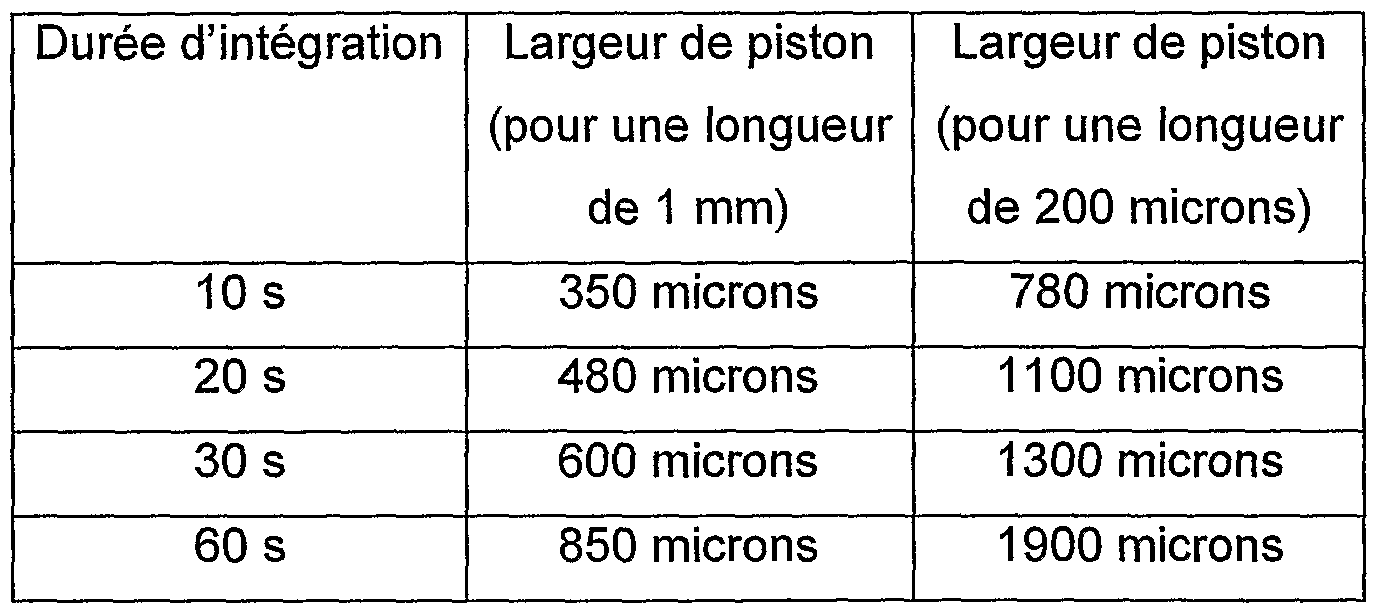
De nombreuses variantes sont possibles, en particulier sur les matériaux. Différents substrats peuvent être utilisés : SOI, silicium, verre, quartz, etc. de façon générale tous les substrats semi-conducteurs, les polymères, les céramiques, les métaux. Si aucune lecture optique n'est prévue au travers du couvercle, celui-ci peut être un matériau opaque. Les parties mécaniques mobiles peuvent être réalisées par empilement successif de couches de polymère sur un substrat quelconque (le substrat sert uniquement de support mécanique dans ce cas). D'autres solutions techniques permettent de réaliser les parties mécaniques en métal (procédé LIGA, électrodéposition de métal, etc.). Le liquide utilisé pour le remplissage des cavités peut être de l'eau ou tout autre liquide sensiblement incompressible, selon les besoins, par exemple un alcool tel que l'alcool isopropyl.
Des étapes supplémentaires de traitement peuvent être utiles à la réalisation du dispositif (étapes de dopage du semi-conducteur, métallisation... pour la lecture de l'information).Many variations are possible, especially on materials. Different substrates can be used: SOI, silicon, glass, quartz, etc. generally all semiconductor substrates, polymers, ceramics, metals. If no optical reading is provided through the cover, it may be an opaque material. The moving mechanical parts can be made by successive stacking of polymer layers on any substrate (the substrate serves only mechanical support in this case). Other technical solutions make it possible to produce metal mechanical parts (LIGA process, metal plating, etc.). The liquid used for filling the cavities may be water or any other substantially incompressible liquid, as required, for example an alcohol such as isopropyl alcohol. Additional processing steps may be useful for producing the device (semiconductor doping steps, metallization ... for reading the information).
La lecture de l'information de verrouillage peut être envisagée en réalisant des reprises de contact en face arrière (de type via), ou en face avant par métallisation de certaines surfaces. Dans cette configuration, le liquide employé doit garantir une isolation électrique en l'absence de contact mécanique (tant que le verrouillage mécanique n'a pas eu lieu).The reading of the locking information can be envisaged by performing contact overlays on the rear face (via type), or on the front face by metallization of certain surfaces. In this configuration, the liquid used must guarantee electrical insulation in the absence of mechanical contact (as long as the mechanical locking has not taken place).
On peut noter que selon l'invention : - les techniques de fabrication employées peuvent être des techniques de la micro-électronique, adaptées à une fabrication collective,It may be noted that according to the invention: the manufacturing techniques employed may be microelectronics techniques, suitable for collective fabrication,
- l'information saisie peut être qu'une accélération supérieure à un seuil donné a été subie pendant un laps de temps important, paramétré durant la phase de conception, et mémorisé par la position de la partie mobile, - les étranglements peuvent générer des pertes de charge importantes lors de l'écoulement du fluide,the information entered may be that an acceleration greater than a given threshold has been experienced during a significant lapse of time, parameterized during the design phase, and memorized by the position of the mobile part, the restrictions may generate losses significant load during the flow of the fluid,
- ce dispositif peut ainsi être un intégrateur,this device can thus be an integrator,
- ce dispositif de mesure est autonome, ne nécessitant pas d'électronique de traitement pour mémoriser l'information, - le dispositif est simple (en particulier, il ne nécessite pas de microengrenages ou de micro-mécanismes complexes.- This measuring device is autonomous, does not require processing electronics to store the information, - the device is simple (in particular, it does not require complex micro-gears or micro-mechanisms.
Un dispositif selon l'invention se prête à de très nombreuses applications ; c'est ainsi qu'il peut, par exemple, servir à la détection locale de séismes en vue de la mise en sécurité automatique de certains réseaux (par exemple, désactiver automatiquement un réseau électrique pour éviter des incendies) ou de certains appareils.
A device according to the invention lends itself to many applications; for example, it can be used for the local detection of earthquakes for the automatic safety of certain networks (for example, automatically disable an electrical network to prevent fires) or certain devices.
Claims
1. Dispositif micro-électronique inertiel comportant, dans un empilement de couches, une enceinte et une masse reliée à la paroi de cette enceinte par des éléments déformables en sorte d'être mobile dans cette enceinte parallèlement aux couches suivant une unique direction dite direction sensible, cette masse mobile étant montée mobile dans un alésage de l'enceinte en sorte de former un étranglement séparant cette enceinte en deux cavités, cette enceinte étant remplie par un fluide sensiblement incompressible formant une phase unique.1. Inertial microelectronic device comprising, in a stack of layers, an enclosure and a mass connected to the wall of this enclosure by deformable elements so as to be movable in this enclosure parallel to the layers in a single direction said sensitive direction said movable mass being movably mounted in a bore of the enclosure so as to form a constriction separating said enclosure into two cavities, this chamber being filled with a substantially incompressible fluid forming a single phase.
2. Dispositif selon la revendication 1 , caractérisé en ce que le fluide sensiblement incompressible est de l'eau.2. Device according to claim 1, characterized in that the substantially incompressible fluid is water.
3. Dispositif selon la revendication 2, caractérisé en ce que certaines des parois de l'enceinte sont traitées en sorte d'être hydrophobes.3. Device according to claim 2, characterized in that some of the walls of the chamber are treated so as to be hydrophobic.
4. Dispositif selon la revendication 2 ou la revendication 3, caractérisé en ce que certaines des parois de l'enceinte sont traitées en sorte d'être hydrofuges.4. Device according to claim 2 or claim 3, characterized in that some of the walls of the enclosure are treated so as to be water-repellent.
5. Dispositif selon l'une quelconque des revendications 1 à 4, caractérisé en ce que l'intérieur de l'enceinte ne comporte que des angles internes arrondis.5. Device according to any one of claims 1 to 4, characterized in that the interior of the enclosure has only rounded internal angles.
6. Dispositif selon l'une quelconque des revendications 1 à 5, caractérisé en ce que les deux cavités sont de largeurs différentes transversalement à la direction sensible, les éléments déformables étant dans la cavité de plus grande largeur et l'alésage étant défini par la paroi de la cavité de plus petite largeur.6. Device according to any one of claims 1 to 5, characterized in that the two cavities are of different widths transverse to the sensitive direction, the deformable elements being in the cavity of greater width and the bore being defined by the wall of the cavity of smaller width.
7. Dispositif selon l'une quelconque des revendications 1 à 6, caractérisé en ce que la masse mobile comporte une portion élargie formant un piston délimitant l'étranglement conjointement avec l'alésage.7. Device according to any one of claims 1 to 6, characterized in that the movable mass comprises an enlarged portion forming a piston defining the constriction together with the bore.
8. Dispositif selon l'une quelconque des revendications 1 à 7, caractérisé en ce que l'empilement de couches comporte une couche formant un fond, une couche dans laquelle sont formés la masse mobile et les éléments déformables, d'un seul tenant, et une couche formant un couvercle.8. Device according to any one of claims 1 to 7, characterized in that the stack of layers comprises a layer forming a bottom, a layer in which are formed the movable mass and the deformable elements, in one piece, and a layer forming a lid.
9. Dispositif selon la revendication 8, caractérisé en ce que l'une des couches formant le fond ou le couvercle est transparente. 9. Device according to claim 8, characterized in that one of the layers forming the bottom or the lid is transparent.
10. Dispositif selon la revendication 9, caractérisé en ce que cette couche est en verre.10. Device according to claim 9, characterized in that this layer is made of glass.
11. Dispositif selon l'une quelconque des revendications 8 à 10, caractérisé en ce que la couche dans laquelle sont formés la masse mobile et les éléments déformables est une couche de silicium.11. Device according to any one of claims 8 to 10, characterized in that the layer in which are formed the mobile mass and the deformable elements is a silicon layer.
12. Dispositif selon la revendication 11 , caractérisé en ce que la couche formant le fond est en silicium et est séparée de la couche dans laquelle sont formés la masse mobile et les éléments déformables par une couche d'oxyde. 12. Device according to claim 11, characterized in that the layer forming the bottom is silicon and is separated from the layer in which are formed the mobile mass and the deformable elements by an oxide layer.
13. Dispositif selon la revendication 12, caractérisé en ce que la distance entre le fond de l'enceinte et la masse mobile est l'épaisseur d'oxyde.13. Device according to claim 12, characterized in that the distance between the bottom of the chamber and the moving mass is the oxide thickness.
14. Dispositif selon l'une quelconque des revendications 8 à 13, caractérisé en ce que la distance entre le couvercle de l'enceinte et la masse mobile est la profondeur d'un creux ménagé dans la couche formant ce couvercle.14. Device according to any one of claims 8 to 13, characterized in that the distance between the housing cover and the moving mass is the depth of a recess in the layer forming the cover.
15. Dispositif selon la revendication 14, caractérisé en ce que le fond du creux ménagé dans la couche formant le couvercle est recouverte d'une couche de nitrure de silicium.15. Device according to claim 14, characterized in that the bottom of the hollow formed in the layer forming the lid is covered with a layer of silicon nitride.
16. Dispositif selon l'une quelconque des revendications 1 à 15, caractérisé en ce que l'enceinte comporte au moins deux orifices de remplissage (O) obturés de manière étanche, dont un orifice débouchant dans chaque cavité.16. Device according to any one of claims 1 to 15, characterized in that the enclosure comprises at least two filling orifices (O) sealingly closed, including an orifice opening into each cavity.
17. Dispositif selon l'une quelconque des revendications 1 à 16, caractérisé en ce qu'il comporte un dispositif de lecture. 17. Device according to any one of claims 1 to 16, characterized in that it comprises a reading device.
18. Dispositif selon la revendication 17, caractérisé en ce que ce dispositif de lecture est optique, le dispositif comportant une portion transparente prévue pour permettre cette lecture optique.18. Device according to claim 17, characterized in that this reading device is optical, the device comprising a transparent portion provided to allow this optical reading.
19. Dispositif selon la revendication 17, caractérisé en ce qu'il comporte en outre un dispositif de verrouillage. 19. Device according to claim 17, characterized in that it further comprises a locking device.
20. Dispositif selon la revendication 19, caractérisé en ce que le dispositif de verrouillage et le dispositif de lecture sont dans des cavités différentes. 20. Device according to claim 19, characterized in that the locking device and the reading device are in different cavities.
21. Procédé de fabrication d'un dispositif micro-électronique inertiel selon l'une quelconque des revendications 1 à 20, caractérisé en ce que l'on forme un empilement de couches , on y définit une enceinte, une masse reliée à la paroi de cette enceinte par des éléments déformables en sorte d'être mobile dans cette enceinte parallèlement aux couches suivant une unique direction sensible, cette masse étant montée mobile dans un alésage de l'enceinte en sorte de former un étranglement séparant cette enceinte en deux cavités, et on remplit cette enceinte par un fluide sensiblement incompressible formant une phase unique. 21. A method of manufacturing an inertial microelectronic device according to any one of claims 1 to 20, characterized in that one forms a stack of layers, there is defined an enclosure, a mass connected to the wall of this enclosure by deformable elements so as to be mobile in this chamber parallel to the layers in a single sensitive direction, the mass being movably mounted in a bore of the enclosure so as to form a constriction separating said enclosure into two cavities, and this chamber is filled with a substantially incompressible fluid forming a single phase.
22. Procédé selon la revendication 21 , caractérisé en ce que l'on forme l'empilement de couches en sorte de laisser temporairement dégagé au moins un orifice de remplissage, et on fait dégazer le liquide de remplissage, on met l'enceinte sous vide et on la remplit avec ce liquide de remplissage.22. The method as claimed in claim 21, characterized in that the stack of layers is formed so as to temporarily leave at least one filling orifice open, and the filling liquid is degassed, the enclosure is evacuated. and filled with this filling liquid.
23. Procédé selon la revendication 22, caractérisé en ce qu'en outre, on fait dégazer un liquide de remplissage temporaire, on remplit l'enceinte avec ce liquide de remplissage temporaire et on remplace ce dernier par le liquide de remplissage.23. A method according to claim 22, characterized in that in addition, a temporary filling liquid is degassed, the chamber is filled with this temporary filling liquid and the latter is replaced by the filling liquid.
24. Procédé selon la revendication 23, caractérisé en ce que le liquide de remplissage temporaire est un liquide présentant une tension de surface inférieure à celle du liquide de remplissage.24. The method of claim 23, characterized in that the temporary filling liquid is a liquid having a lower surface tension than the filling liquid.
25. Procédé selon la revendication 23 ou la revendication 24, caractérisé en ce que le liquide de remplissage temporaire est un alcool.25. The method of claim 23 or claim 24, characterized in that the temporary filling liquid is an alcohol.
26. Procédé selon l'une quelconque des revendications 22 à 25, caractérisé en ce que le liquide de remplissage est de l'eau. 26. Process according to any one of claims 22 to 25, characterized in that the filling liquid is water.
27. Procédé selon l'une quelconque des revendications 21 à 26, caractérisé en ce que l'on remplit l'enceinte par un orifice de remplissage et on aspire au moins une partie de ce liquide par un orifice d'aspiration.27. Method according to any one of claims 21 to 26, characterized in that the chamber is filled by a filling port and at least a portion of this liquid is sucked by a suction port.
28. Procédé selon l'une quelconque des revendications 21 à 27, caractérisé en ce que l'on vérifie le bon remplissage de l'enceinte par contrôle visuel au travers d'une portion transparente du dispositif. 28. A method according to any one of claims 21 to 27, characterized in that it verifies the proper filling of the chamber by visual inspection through a transparent portion of the device.
Priority Applications (3)
| Application Number | Priority Date | Filing Date | Title |
|---|---|---|---|
| EP07731286A EP2005198B1 (en) | 2006-04-12 | 2007-04-12 | Inertial micro-electronic device with liquid integrator |
| DE602007007592T DE602007007592D1 (en) | 2006-04-12 | 2007-04-12 | MICROELECTRONIC DEFLECTION DEVICE WITH LIQUID INTEGRATOR |
| AT07731286T ATE473449T1 (en) | 2006-04-12 | 2007-04-12 | MICROELECTRONIC INERTIAL DEVICE WITH LIQUID INTEGRATOR |
Applications Claiming Priority (2)
| Application Number | Priority Date | Filing Date | Title |
|---|---|---|---|
| FR0603242 | 2006-04-12 | ||
| FR0603242A FR2899889B1 (en) | 2006-04-12 | 2006-04-12 | INERTIAL MICROELECTRONIC DEVICE WITH LIQUID INTEGRATOR |
Publications (1)
| Publication Number | Publication Date |
|---|---|
| WO2007116156A1 true WO2007116156A1 (en) | 2007-10-18 |
Family
ID=37496518
Family Applications (1)
| Application Number | Title | Priority Date | Filing Date |
|---|---|---|---|
| PCT/FR2007/000618 WO2007116156A1 (en) | 2006-04-12 | 2007-04-12 | Inertial micro-electronic device with liquid integrator |
Country Status (5)
| Country | Link |
|---|---|
| EP (1) | EP2005198B1 (en) |
| AT (1) | ATE473449T1 (en) |
| DE (1) | DE602007007592D1 (en) |
| FR (1) | FR2899889B1 (en) |
| WO (1) | WO2007116156A1 (en) |
Citations (4)
| Publication number | Priority date | Publication date | Assignee | Title |
|---|---|---|---|---|
| US3046793A (en) * | 1960-04-04 | 1962-07-31 | Gen Precision Inc | Hydraulic averaging accelerometer |
| GB2283098A (en) * | 1993-10-20 | 1995-04-26 | Autoliv Dev | Accelerometer using inertia mass in a fluid e.g.air |
| US20020002864A1 (en) * | 2000-07-10 | 2002-01-10 | Terje Kvisteroey | Accelerometer |
| US6453746B1 (en) * | 2000-06-07 | 2002-09-24 | Sandia Corporation | Microscale acceleration history discriminators |
-
2006
- 2006-04-12 FR FR0603242A patent/FR2899889B1/en not_active Expired - Fee Related
-
2007
- 2007-04-12 EP EP07731286A patent/EP2005198B1/en not_active Not-in-force
- 2007-04-12 AT AT07731286T patent/ATE473449T1/en not_active IP Right Cessation
- 2007-04-12 DE DE602007007592T patent/DE602007007592D1/en active Active
- 2007-04-12 WO PCT/FR2007/000618 patent/WO2007116156A1/en active Application Filing
Patent Citations (4)
| Publication number | Priority date | Publication date | Assignee | Title |
|---|---|---|---|---|
| US3046793A (en) * | 1960-04-04 | 1962-07-31 | Gen Precision Inc | Hydraulic averaging accelerometer |
| GB2283098A (en) * | 1993-10-20 | 1995-04-26 | Autoliv Dev | Accelerometer using inertia mass in a fluid e.g.air |
| US6453746B1 (en) * | 2000-06-07 | 2002-09-24 | Sandia Corporation | Microscale acceleration history discriminators |
| US20020002864A1 (en) * | 2000-07-10 | 2002-01-10 | Terje Kvisteroey | Accelerometer |
Also Published As
| Publication number | Publication date |
|---|---|
| EP2005198B1 (en) | 2010-07-07 |
| FR2899889A1 (en) | 2007-10-19 |
| ATE473449T1 (en) | 2010-07-15 |
| EP2005198A1 (en) | 2008-12-24 |
| DE602007007592D1 (en) | 2010-08-19 |
| FR2899889B1 (en) | 2008-07-04 |
Similar Documents
| Publication | Publication Date | Title |
|---|---|---|
| EP3185011B1 (en) | Microelectromechanical or nanoelectromechanical gas sensor | |
| EP1949145B1 (en) | Making a two-phase liquid/liquid or gas system in microfluidics | |
| EP0626572B1 (en) | Diaphragm pressure transducer comprising a shock protective system, and gradiomanometer incorporating such a transducer | |
| EP2609993B1 (en) | Micro and nano fluid device for separating and concentrating particles contained in a fluid | |
| EP1780495B1 (en) | Small-sized pyrothechnic safety device. | |
| EP2796884A1 (en) | Microelectromechanical and/or nanoelectromechanical structure with ajustable quality factor | |
| EP2921836A1 (en) | Sensor for measuring microelectromechanical and/or nanoelectromechanical differential pressure | |
| EP2702275B1 (en) | Micropump having a flowmeter, and method for producing same | |
| EP2520900B1 (en) | Gyroscope with reduced parasitic capacitance | |
| FR2919074A1 (en) | OPTICAL DEVICE WITH MEMBRANE DEFORMABLE BY ELECTROSTATIC ACTUATION | |
| FR3037152A1 (en) | OPTICAL DEVICE WITH VARIABLE OPENING | |
| EP3538479B1 (en) | Device for transmitting a movement and a force between two zones that are insulated from one another | |
| FR2994228A1 (en) | PUMP REALIZED IN A SUBSTRATE | |
| FR2951713A1 (en) | MICRO-SHUTTER WITH ELECTROMAGNETIC ACTUATION | |
| WO2016097302A2 (en) | Dynamic pressure sensor with improved operation | |
| EP2005198B1 (en) | Inertial micro-electronic device with liquid integrator | |
| EP3156361A1 (en) | Electromechanical microsystem and manufacturing method | |
| EP3217181B1 (en) | Damped linear accelerometer | |
| EP3159302A1 (en) | Method for encapsulating a microelectronic component | |
| FR2817974A1 (en) | OPTICAL MICRO-ACTUATOR, OPTICAL COMPONENT USING THE MICRO-ACTUATOR, AND METHOD FOR PRODUCING AN OPTICAL MICRO-ACTUATOR | |
| FR2948993A1 (en) | PRIMING SECURITY DEVICE FOR ROTATING AMMUNITION | |
| EP0931250B1 (en) | Cell for converting differential pressure into an electric signal | |
| EP4098608A1 (en) | Electromechanical microsystem | |
| EP2292553B1 (en) | Component and process for reversibly sealing a microcapsule package | |
| EP4015446A1 (en) | Electromechanical microsystem |
Legal Events
| Date | Code | Title | Description |
|---|---|---|---|
| 121 | Ep: the epo has been informed by wipo that ep was designated in this application |
Ref document number: 07731286 Country of ref document: EP Kind code of ref document: A1 |
|
| WWE | Wipo information: entry into national phase |
Ref document number: 2007731286 Country of ref document: EP |
|
| NENP | Non-entry into the national phase |
Ref country code: DE |