WO2007101944A2 - Method and device for separating fractions of a mixture - Google Patents
Method and device for separating fractions of a mixture Download PDFInfo
- Publication number
- WO2007101944A2 WO2007101944A2 PCT/FR2007/000406 FR2007000406W WO2007101944A2 WO 2007101944 A2 WO2007101944 A2 WO 2007101944A2 FR 2007000406 W FR2007000406 W FR 2007000406W WO 2007101944 A2 WO2007101944 A2 WO 2007101944A2
- Authority
- WO
- WIPO (PCT)
- Prior art keywords
- characteristic point
- history
- mixture
- collection
- purity
- Prior art date
Links
Classifications
-
- B—PERFORMING OPERATIONS; TRANSPORTING
- B01—PHYSICAL OR CHEMICAL PROCESSES OR APPARATUS IN GENERAL
- B01D—SEPARATION
- B01D15/00—Separating processes involving the treatment of liquids with solid sorbents; Apparatus therefor
- B01D15/08—Selective adsorption, e.g. chromatography
- B01D15/10—Selective adsorption, e.g. chromatography characterised by constructional or operational features
- B01D15/18—Selective adsorption, e.g. chromatography characterised by constructional or operational features relating to flow patterns
- B01D15/1814—Selective adsorption, e.g. chromatography characterised by constructional or operational features relating to flow patterns recycling of the fraction to be distributed
- B01D15/1821—Simulated moving beds
- B01D15/1828—Simulated moving beds characterized by process features
-
- B—PERFORMING OPERATIONS; TRANSPORTING
- B01—PHYSICAL OR CHEMICAL PROCESSES OR APPARATUS IN GENERAL
- B01D—SEPARATION
- B01D15/00—Separating processes involving the treatment of liquids with solid sorbents; Apparatus therefor
- B01D15/08—Selective adsorption, e.g. chromatography
- B01D15/10—Selective adsorption, e.g. chromatography characterised by constructional or operational features
- B01D15/18—Selective adsorption, e.g. chromatography characterised by constructional or operational features relating to flow patterns
- B01D15/1814—Selective adsorption, e.g. chromatography characterised by constructional or operational features relating to flow patterns recycling of the fraction to be distributed
- B01D15/1857—Reactive simulated moving beds
Definitions
- the present invention relates to a method and a device for separating fractions of a mixture, by chromatography.
- Chromatography is a separation method based on the difference in product distribution of a mixture between a mobile phase (eluent or solvent) and a stationary phase.
- the products are separated by percolating a liquid, gaseous or supercritical fluid in a device (a column) filled with stationary solid or liquid phase.
- This method is implemented as an analytical technique to identify and quantify the products of a mixture. It can also be used as a separation or purification technique.
- composition of the eluent can be isocratic or a gradient can be made.
- FR 2 699 917 (US Pat. No. 5,569,808) of the French Petroleum Institute describes a method of regulating a process for the separation of at least one aromatic hydrocarbon isomer having from 8 to 10 carbon atoms. carbon, contained in a mixture comprising at least two of said isomers, said process comprising a separation step under suitable conditions in a separation zone.
- Said method comprises the steps a) simultaneously sending at least two appropriate points of said zone, other than effluent sampling points, a monochromatic light signal having a wavelength of between 400 and 1300 nanometers, and preferably between 420 and and 650 nanometers; b) recovering a polychromatic scattered signal corresponding to the Raman effect between 400 and 3500 cm -1 , and preferably between 600 and 1200 cm -1 substantially at said points; c) simultaneous sending of at least the two signals recovered on a multichannel spectrometer delivering the corresponding Raman spectra; d) determining from the two spectra the chemical composition of the mixture at each of the two points; e) repeating the sequence of steps a, b, c and d so as to reconstitute the concentration profiles of the two isomers contained in the mixture, and f) comparing the concentration profiles obtained with reference concentration profiles and acts on at least one operating variable of the separation process to regulate it.
- the article "Optimal operation of simple circulating bed chromatographic processes by simple feedback control" by H. Schramm, S. Griiner, A. Kienle, Journal of Chromatography A, 1006 (2003), 3-13 describes two methods for controlling a Simulated Moving Bed (LMS) device.
- LMS Simulated Moving Bed
- the device is equipped with UV sensors, each of the sensors being arranged in a separation zone.
- the UV profile is recorded as the sum of the concentrations of the components in the device.
- four different separation fronts can be observed in the concentrations as well as in the UV profile.
- PI controllers calculate flow rate ratios m for each of the separation zones. Rates in each zone are then calculated to control the Simulated Mobile Bed device.
- the set points are for example such that the fronts of the concentration profiles are located in the middle of the different separation zones.
- the document describes a second method of control based on the knowledge of a model.
- model-based control is not satisfied with a UV profile and access to concentrations is necessary through a state observer.
- the model makes it possible to calculate by simulation the best operating conditions to satisfy the purity constraints of the output products.
- the model is then readjusted according to the results of purities obtained during the separation.
- the limitation of this method lies in the accuracy of the observer - state allowing from the UV profile to go back to the concentration profile and in the knowledge of the model of the separation, which needs to be determined in advance as accurately as possible.
- US-A-5,457,260 discloses a method for continuously controlling at least one feature of a Simulated Moving Bed (LMS) method.
- the Simulated Mobile Bed is realized by means of a rotary valve allowing the shift of the charge and eluent injection and the offset of the extraction of the extract and the raffinate on a cycle of operation.
- the controlled characteristics can be the purity or the yield of the component of interest.
- the method comprises the steps of (a) determining the concentration of at least one component in the circulating fluid at a minimum of three valve positions within a valve cycle (b) determining the current value of the characteristic using all the determined concentrations within a valve cycle; (c) adjusting the valve rotation period and flow rates according to an algorithm; (d) repeating steps a) to c) until the difference between the current value of the characteristic and a set value is below a threshold.
- US-A-2005 107895 discloses a control method using MPC control ("Model Predictive Control").
- An approximate model of the process makes it possible to predict the future evolution of the system from concentration measurements of the output products.
- an optimizer selects the operating parameters to be applied in order to reach the specifications fixed on the output products. Once the specifications are reached, the operating parameters are adjusted again to increase the performance of the process.
- the method requires a complex algorithm as well as a representation model of the separation.
- Document FR-A-2 762 793 (US-A-5 902 486) describes a method for controlling a Simulated Mobile Beds Component Separation System (or Unit) comprising a closed loop constituted by the interconnection in series of beds containing adsorbent solid material, divided into several zones delimited by injection points and fluid extraction points, means for injecting fluids into the loop, means for extracting fluids out of the loop, means for permutation of the injection points and extraction points, making it possible to simulate the displacement of the beds against the current, and means for measuring various variables
- the method comprises (a) measuring operating variables such as flow rates or the period and measuring concentrations of certain constituents necessary for the calculation of variables controlled at a number of points of the separation loop of at least two; (b) determining, based on current values of measured variables, and using a non-linear model of the operation of the ratio separation system (Rk) indicative of the ratio in each of the different zones, respectively, between the fluid flow rates ( QK) and the simulated flow rates of adsorbent material (Qs) so as to bring or reduce the controlled variables (such as purity or yield) to specific setpoint values; and (c) the determination from these ratios (Rk) of the values to be given to the operating variables (flow rates or period).
- Rk ratio separation system
- This method also has the disadvantage of using a separation model.
- DE-A-198 42 550 describes a method for optimizing a Simulated Mobile Bed type chromatographic method for estimating separation parameters.
- measurements are made on each of the output lines to determine a characteristic such as concentration.
- the physical behavior of the system is determined.
- the invention proposes a process for fraction separation of a mixture in a chromatography device having one or more columns in a loop, a moving mobile phase displacing the fractions of the mixture to be separated in said loop,
- the method comprising steps of collecting fractions, mixing injection between two successive collections in the interval where the fractions of the mixture leave the column or columns and are sent to the next entry, the method further comprising the steps of: controlling in a node of the device, the history of a specific variable of the fractions of the mixture to be separated,
- the device comprises at least one chromato graphy column and collection points where the fractions are collected, one of the fractions, the extract, is retained more in the column than the other fraction, the raffinate, less restrained in the column.
- the device comprises mixing and eluent injection points and fraction collection points, injection and collection point sequencing members, the method comprising sequencing the injection points and collection to their original position in the device after one cycle of operation.
- the history is controlled on a cycle of operation of the device. According to one variant, the history is controlled on less than one cycle, until the appearance of the characteristic point of the history.
- control of the history is carried out at a frequency corresponding to an integer number of operating cycles of the device. According to one variant, the control of the history is carried out in a single node.
- a single characteristic point is detected between two successive collections, the duration of each collection being included, framing the injection of the mixture to be treated.
- the amount of mobile phase is modified by the variation of the average flow rate of mobile phase.
- the device has a cyclic operation, and during the adjustment step, the amount of mobile phase is modified by the variation of the cycle time.
- the process further comprises the steps of: measuring the purity of at least one fraction collected, comparing the purity measured with a predetermined purity, the method further comprising a step of defining the target point depending on the difference between the measured purity and the predetermined purity.
- the process further comprises the steps of: - measuring the purity of at least two collected fractions; - comparing the measured purity of the fractions with a predetermined purity, the method further comprising a step of defining the target position as a function of the difference between the measured purities and the predetermined purities.
- the target position is defined following the modification of the position of the injection of mixture on the history.
- the process further comprises the steps of: measuring the purity of at least one fraction collected, comparing the purity measured with a predetermined purity, the method further comprising a step of modifying the quantity mixture injected as a function of the difference between the measured purity and the predetermined purity.
- the method further comprises the steps of measuring the purity of at least two collected fractions, comparing the measured purity of the fractions with respectively a predetermined purity, the method further comprising a step of modifying the quantity of mixture injected as a function of the difference between the measured purities and the predetermined purities.
- the amount of mixing is increased if the purities measured are greater than the predetermined purities.
- the amount of mixing is decreased if the measured purities are lower than the predetermined purities.
- the method further comprises steps of controlling a node of the device, the history of a specific variable of the fractions of the mixture to be separated, the detection of a second characteristic point of the history, dedicated adsorbing or collecting a fraction of the less retained mixture, located between the less restrained fraction withdrawal or collection step and the eluent injection step; - Comparison of the position of the characteristic point with respect to a target position, - Setting the amount of the mobile phase changing the position of the characteristic point to coincide the position of the characteristic point with the target position.
- the device comprises an inlet zone from which a less retained fraction is withdrawn and at the outlet of which eluent is injected, the method comprising, at the adjustment stage, the regulation of the average flow rate in this zone. to match the position of the characteristic point with the target position.
- the duration of the collection step of the least retained fraction is modified to coincide the position of the characteristic point with the target position.
- the method further comprises steps of controlling a node of the device, the history of a specific variable of the fractions of the mixture to be separated, and detecting a third characteristic point of the dedicated history. desorbing or collecting a fraction of the more retained mixture, located between the eluent injection step and the more restrained fraction collection or withdrawal step; comparing the position of the characteristic point with respect to a target position; - Setting the amount of the mobile phase changing the position of the characteristic point to coincide the position of the characteristic point with the target position.
- the device comprises an input zone from which eluent is injected and at the outlet of which a more retained fraction is withdrawn
- the method comprises, at the adjustment step, the regulation of the average flow rate in this zone. to match the position of the characteristic point with the target position.
- the duration of the collection step of the most restrained fraction is modified to coincide the position of the characteristic point with the target position.
- the observation nodes are chosen at different locations or at the same locations.
- the histories are different or are the same.
- the specific variables are different or are the same.
- the control is performed at a node other than a collection point of fractions.
- the characteristic point is chosen from the group consisting of a point of inflection of the history, a threshold of the history, an extremum of the history, a zero value, a defined slope of history.
- the specific variable is chosen from the group consisting of the rotary power, the adsorption of spectroscopic radiation, the emission of spectroscopic radiation, the density, the refractive index, the conductivity, pH.
- the adjustment of the mobile phase volume is performed by adjusting the collection rate of a fraction.
- the injection of mixture is continuous.
- the device comprises several columns connected in series.
- the chromatographic device is adapted to the VariCol process, or to the Simulated Mobile Bed process.
- the device comprises an inlet zone from which a fraction is withdrawn and at the outlet of which the mixture to be separated is injected, the method comprising, at the adjustment step, the adjustment of the average flow rate of this zone to make coincide the position of the characteristic point with the target position.
- the injection of mixture is discontinuous.
- the device comprises one or two columns.
- the device is adapted to the CycloJet process.
- the process is automatic.
- the invention also relates to a fraction separation device of a chromatographic mixture comprising the implementation of the preceding method.
- the chromatography device comprises a control logic adapted to implementing the preceding method.
- the device comprises detectors located on the recycling line. According to one variant, the device comprises remote detectors. According to one variant, the device comprises an analytical apparatus, the purity of the fractions is measured by the analytical apparatus.
- the invention also relates to the use of the preceding method for the separation and / or purification of mixture of interests.
- the invention also relates to the use of the preceding method for the separation and / or purification of enantiomers.
- the invention also relates to the use of the above method for the separation and / or purification of molecules.
- the invention also relates to the use of the above method for the separation and / or purification of proteins.
- the invention also relates to the use of the above method for the separation and / or purification of antibodies.
- the invention also relates to the use of the above method for the separation and / or purification of pharmaceutical compounds.
- FIG. a Simulated Mobile Bed device FIGS. 2 to 5, representations of the device CycloJ and; FIGS. 6 to 11, examples of operation and movement of the fractions of the mixture to be separated in a continuous injection device; FIGS. 12 to 16, examples of operation and movement of the fractions of the mixture to be separated in a discontinuous injection device; FIGS. 17 to 23, exemplary embodiments of the control of specific variables;
- the invention relates to a process for separating fractions of a mixture to be separated, in a chromatography device.
- the device has one or more columns of loop chromatography; a mobile phase circulates in the device and moves the fractions of the mixture to be separated.
- the method includes fraction collection and mixture injection steps; injection of mixture takes place between two successive collections of a product or a set of poorly selected products and a product or a set of products more retained, while the fractions of the mixture being separated out of the column or columns and are sent to the next column entry.
- the mode of collection of the fractions can be carried out in different ways, we will speak more precisely of withdrawal when a partial sampling of mobile phase is carried out at the column outlet, the rest being injected into the next column and we speak of total collection when it is the entire mobile phase flow leaving a column that is collected.
- the method further comprises a step of controlling, at a node of the device, the history of a specific variable of the fractions of the mixture to be separated.
- the method also includes a step of detecting a characteristic point of the history, preferably on the time interval delimited by the start of the collection of a less restrained fraction and the end of the next collection of the most restrained fraction. near the node.
- the method then comprises a step of comparing the position of the characteristic point with respect to a target position, then a step of adjusting the amount of mobile phase modifying the position of the characteristic point to coincide the position of the characteristic point with the target position. .
- the invention makes it possible to simplify the fraction separation process because the process makes it possible to adapt to variations in the conditions for carrying out chromatographic separation; in particular, the method does not require the reconstitution of an operating model of the device.
- the method automatically controls and adjusts the operation of the separation device.
- the method makes it possible to react quickly to a possible disturbance, on a stable device or in the course of stabilization.
- a device mention may be made of the Simulated Mobile Bed device.
- the chromatographic columns may contain stationary liquid or solid phases and eluted with a fluid in the gaseous, liquid or even supercritical state.
- the method is applicable to devices comprising at least one chromatography column filled with a stationary phase and comprising mixing injection points of at least two species and column inlet eluent and collection points. fractions; the devices also include sequencing devices injection and collection points. In particular, the sequencing of these injection and collection points takes place over one operating cycle of the device. Thereafter, a "cyclic operation" or “cycle” designates the time after which the injection and collection points have been sequenced until returning to the initial position in the device. After one cycle, the device is back to its original configuration.
- a cycle has as many periods as columns in the separation loop so the cycle of an 8-column SMB or VariCol device will be produced by 8 periods.
- the cycle consists of a single period; we can then assimilate cycle time and period.
- FIG. 1 shows a device 10 making it possible to implement a method
- the device 10 comprises a set of chromatographic columns or sections of chromatographic columns containing a stationary or adsorbent phase, the columns are connected in series and closed loop.
- the columns have an input and an output, the output of a column being connected to a subsequent column input. For example, twelve columns 121 to 1212 are shown.
- the loop comprises at least one mixing injection point 14 (charge), a product-enriched fraction collection point 16 that is little retained by the stationary phase (fraction called raffinate), an injection point 18 of an eluent, and a product-enriched fraction collection point 20 less retained by the stationary phase (fraction called extract).
- the mixing injection point 14 is between the columns 128 and 129, the raffinate collection point 16 is between the columns 1210 and 1211, the eluent injection point 18 is between the columns 122 and 123 and the point Extract collection is between columns 125 and 126.
- the device operates by synchronous sequencing, that is to say by synchronous shift of all the points of injection and withdrawal of a column or column section in a direction 22 defined with respect to the direction of the flow of a main fluid flowing through the loop.
- the offset of the set of points of a column or section of a column corresponds to a period; at the end of a cycle, all the points have returned to their initial position, the device having a cyclic operation.
- a cycle has as many periods as there are columns or column sections.
- the VariCol process differs from the SMB process in that during a cycle, the sequencing or shifting of the different injection and withdrawal points of a column or column section is carried out at different times so that the length of the zones defined by said different points is variable. Sequencing or shifting of points is asynchronous.
- a period is the time after which all the points have been shifted by one column or section of a column.
- a cycle has as many periods as columns or sections of a column.
- a chromatographic zone In the devices making it possible to implement the SMB and / or VariCol processes, it is possible to determine between an injection point and a collection point or vice versa a chromatographic zone; thus one can define a zone 1 between the eluent injection point 18 and the extract collection point, a zone 2 between the extract collection point and the mixture injection point 14, a zone 3 between the mixing injection point 14 and the raffinate collection point 16 and a zone 4 between the raffinate collection point 16 and the eluent injection point 18. Zones 2 and 3 form a separation zone, zone 1 forms a desorption zone and zone 4 forms an adsorption zone.
- the SMB and VariCol processes can be implemented with a configuration of less than four zones, for example three zones (by elimination of zone 4). In the latter case, the device operates in an open loop, the entire fluid from the zone 3 being collected at the collection point 16 of raffinate.
- Figures 2 to 4 show a device 10 for implementing a CycloJet process. This device may comprise a single column; it is described in EP-A-0 981 399.
- FIG. 2 shows a chromatography column 12 filled with a stationary phase.
- the device 10 comprises injection points 18 of eluent and total fraction collection 16. In FIG.
- the device 10 is in the process of carrying out a step of total collection of a fraction, for example a fraction enriched in product that is little retained by the stationary phase, also called raffinate.
- a recycling step is shown, the output of the column 12 being connected to the input of the column 12; during this step, a mixing injection takes place at point 14.
- the column is in a closed loop, the output of the column being connected to the next column entry, in this case the same column.
- the injection point 14 is for example an injection loop; the injection loop is loaded in mixture and the injection is carried out by deriving the fluid at the outlet of the column through the loop before injecting the fluid at the column inlet, which allows to insert a volume of mixture into the mixture during separation.
- Figure 4 shows a total fraction collection point.
- the device 10 is in the course of carrying out a total collection step of another fraction, for example a fraction enriched in product more retained by the stationary phase, also called extract.
- the injection points 14 and 18 have been sequenced; in fact, the device alternately comprises at the inlet of the column the injection of mixture or the injection of eluent.
- the collection points 16 and 20 have been sequenced; indeed, at the column outlet 12, the device comprises the raffinate collection point 16, when it is a question of collecting the raffinate, or the device comprises the extract collection point 20, when it is a question of collecting the raffinate. to collect the extract.
- FIG. 5 shows the two-column CycloJet device, in which a preparative chromatographic cyclic process is applied, comprising, in steady-state mode: (a) establishing a profile eight-way flow chromatography, between two chromatographic columns 121 and 22, knowing that said chromatographic profile never passes through an elution pump;
- the principle is therefore based on the use of an external recycling system to avoid the transit of the recycled fraction in the elution pump.
- the devices for implementing the SMB and VariCol processes are continuous injection devices in the sense that the injection of mixture is made over an entire cycle; there may also be devices of the type SMB with three and two zones.
- Other devices such as CycloJet are discontinuous injection devices in the sense that the injection is not made over an entire cycle but for a total duration of less than one cycle; devices such as the Sequential Simulated Moving Bed (SSMB), the iSMB, the Powerfeed (PowerFeed operation of simulated moving flow-rates during the switching interval; Ziyang Zhang, Marco Mazzotti, Massimo Morbidelli; Journal of Chromatography A, 1006 (2003) 87-99), ModiCon (Improved operation of simulated moving bed processes through cyclic modulation of feed flow and feed concentration, H.
- SSMB Sequential Simulated Moving Bed
- iSMB the Powerfeed
- ModiCon Improved operation of simulated moving bed processes through cyclic modulation of feed flow and feed concentration
- the mixture can be binary, that is to say comprising two products; however, the mixture may also contain more than two products.
- the devices described are characterized by the fact that they are storage devices. There is accumulation in a device when the injection of mixture is interposed or added to a non-zero concentration profile passing from the outlet to the inlet of a column. The mixing injection takes place while the fractions of the mixture being separated leave the column (s) and are sent to the next column entry.
- the mixing injection is carried out continuously between two columns, for example by means of an injection pump. The injection adds up to what comes out of the column before entering the next column. The mixture thus injected is therefore added to a non-zero concentration profile; there is accumulation.
- a one-column CycloJet device the injection is carried out while the products leaving the column 12 are returned to the inlet of the same column 12. A volume of fluid containing the mixture to be separated is then inserted between the outlet and the column entry. The mixture thus injected is thus intercalated in a non-zero concentration profile; there is accumulation.
- multi-column devices such as for example a two-column CycloJet or as the subject of patent application FR 0507952 filed in France on July 26, 2005, the injection is carried out while the fractions leaving a column are returned to the input of the next column.
- An injection pump can be used by injecting into a column while, for example, the elution of the previous column is stopped. It is also possible to use an injection loop.
- concentration profile The concentration state of the fractions of the fluid flowing in the device, considered at a time "t" on the entire device, is called a "concentration profile”.
- concentration profile The document FR-2,699,917 (US-A-5,569,808) cited at the beginning of the present description describes steps for reconstructing a concentration profile. In particular, to reconstruct the concentration profile, at least two sensors are arranged in a separation zone of the device.
- a concentration profile is different from a "history" of a specific variable; the term “history” is the state or evolution over time of a specific variable of the fractions of the mixture in motion in the device, state considered for a time or a determined time at a particular point of the device.
- observation node By placing itself at a particular point of the device, which may be called “observation node”, it is possible to control a specific variable of the fractions of the mixture to be separated flowing at the observation node.
- the duration during which the state of the specific variable is determined is, for example, an operating cycle. At the end of the cycle, the history can be reset and restarted. The duration can also be shorter, as will be explained later.
- the raw time the axis then starts from 0 and ends at the effective end of the cycle time;
- the axis of the history is always between 0 and 1;
- a progress index in the cycle is the generalization of the gross time divided by the cycle time; this is interesting in the case where there are scheduled stops of elution rates whose duration can be variable.
- the observation node is a point of the device that can be freely chosen.
- the observation node is a point of the device other than a fraction collection point;
- the observation node is located between the output of the column or columns and the nearest fraction collection point.
- the devices having a cyclic operation it will preferably also be chosen, a point where follow the collection passages fractions enriched in one of the fractions.
- the observation node is at the column outlet, before the collection members, because, in the processes where the collection is total, there is no liquid passing from one column to another; in a device of the SMB or VariCol type, the observation node is for example at a point situated between the output and the input of two columns which follow each other in the device.
- routine designates the implementation of a control principle of the chromatographic device.
- This implementation can take for example the form of a computer algorithm controlling a PLC, more generally, it is a procedure to accomplish a particular task.
- routines are presented with each a defined role.
- a step of the method one places itself in a node of the device and one makes a control of the history of a specific variable of the fractions of the mixture to be separated in the device.
- the specific variable is not the concentration or purity itself of the fractions, or in particular is not a value of the concentration or the purity itself of the fractions. This has the advantage of adjusting the operation more quickly than if a concentration or purity were to be measured; the speed of adjustment is particularly at the start of the process. Moreover, since it is not necessary to measure purity or concentration, it is not necessary to calibrate the detector.
- the advantage of the first routine is that it is not useful either to follow any variation of the calibration over time; thus, after a while, it is not useful to stop the process to verify that the calibration is still correct.
- it is not necessary to physically draw up a history for example by viewing or printing the history; a control without registration or visualization is enough.
- the control step is performed in a single node; this makes it possible to limit the use of detectors and to avoid having to consider the synchronization of the detectors, the synchronization being able to evolve moreover over time in the case for example of a change of state of one of the columns of the device
- Figures 6 to 16 show the control of the history of the concentrations of the fractions of the mixture moving in the device and flowing to the node. observation device for a continuous and discontinuous injection device of a binary mixture.
- FIGS. 6 to 11 show the observation of the concentrations of the fractions of the mixture moving in the device and flowing at the observation node for a device for continuous injection of mixing, in particular, for an SMB device.
- the SMB comprises six columns 121 to 126 as well as mixing and eluent injection points 14, 18 and fraction collection points 16, 20. At point 16 the raffinate is collected and at point 20 is collected the extract.
- the evolution of the internal concentrations of the device is shown in relation to the columns of the device. We will see that the concentration profile moves along the columns, which corresponds to the displacement of the fractions through the mobile phase; the columns being looped, the profile leaving the column 126 reappears in column 121. This is called circulation concentration profile.
- FIGS. 6 to 11 show an operating cycle of the device, comprising six periods of duration ⁇ T (corresponding to six offsets of the injection and collection).
- the abscissa of the history corresponds to a reduced time expressed in number of periods.
- the mixture considered is binary but may also include more than two products. It is also specified that the concentration profile is represented only in order to better understand the evolution of the specific variables controlled at the observation node; there is no question of reconstructing the concentration profile.
- the concentration profile is such that the least retained product concentration has increased and then stabilized; history shows that the least retained product concentration at node 24 has increased and stabilized.
- the least retained product collection point 16 having been shifted one column relative to FIG. 7, the least retained product collection is no longer detected at node 24; on the right-hand part of FIG. 8, the line 26 is interrupted, showing that the collection of the least retained product is no longer made at the column outlet 126.
- the history shows that the concentration of the product most retained at the node 24 is still zero.
- the concentration profile has advanced along the columns. We also see that all the points 14, 16, 18, 20 have been shifted by one column, which corresponds to a new period.
- the concentration profile is such that the least retained product concentration has decreased and the most retained product concentration increases; the history shows that the concentration of the least retained product at node 24 decreases and that the concentration of the most retained product increases. The evolution of the concentrations on the history also shows that the concentrations at node 24 pass through a point 28 where the concentrations are equal.
- FIG. 9 also shows that the injection point 14 is at the column outlet 126 near the node 24.
- the concentration profile advanced along the columns.
- the concentration profile is such that the least retained product concentration is zero and the most retained product concentration decreased;
- the history shows that the least retained product concentration at node 24 is zero and that the most retained product concentration at node 24 has decreased.
- the extract collection point 20 has been shifted out of the column 126; at the node 24 this collection of most retained product is detected, the history including an indication of this collection by the trait referenced 30.
- the concentration profile has advanced along the columns. We also see that all the points 14, 16, 18, 20 have been shifted by one column, which corresponds to a new period.
- a sequence appears to appear in the order of: a step of collecting a fraction enriched in a poorly retained product, for example the raffinate; a so-called accumulation step, where the exit and entry of the column flanking the observation node are interconnected, without collection, but with a mixing injection in a continuous manner;
- the position of the node 24 at the column outlet 126 is an example; if the node were placed in another position, the history would be similar, but shifted in time.
- FIGS. 12 to 16 show the observation of the concentrations of the fractions of the mixture moving in the device and flowing at the observation node for a discontinuous mixing injection device, in particular for a CycloJet device.
- the CycloJet has a column 12 as well as mixing and eluent injection points 14, 18, and fraction collection points 16, 20. In point 16 is collected the least retained product and in point 20 is collected most retained product.
- the evolution of the internal concentrations of the device is shown in relation to the column of the device. We will see that the concentration profile moves along the column, which corresponds to the displacement of the fractions through the mobile phase; when the output of the column 12 is likely to be connected to the input of the column 12, the profile coming out of the column 12 reappears at the input of column 12.
- FIGS. 12 to 16 show an operating cycle of the device, comprising a period (corresponding to a recycling, injection and collection sequence) .
- the abscissa of the history corresponds to the gross time of a cycle.
- the mixture considered is binary but may also include more than two products. It is also specified that the concentration profile is represented only in order to better understand the evolution of the specific variables controlled at the observation node; there is no question of reconstructing the concentration profile.
- Fig. 13 shows a least retained product collection step.
- the concentration profile has advanced along column 12.
- the concentration profile is such that the raffinate concentration has increased; the history shows that the concentration of least retained product at node 24 has increased.
- the collection point 16 of the least retained product appeared at column output 12; at node 24 this collection of least retained product is detected, the history including an indication of this collection by the line referenced 26.
- Figure 14 shows a step where the output of column 12 is connected to the input of the column 12. The injection and collection points are staggered in the sense that the points are not connected. It can be seen that the concentration profile at the column outlet 12 is prolonged at the column inlet 12, testifying to the recycling of little separated fractions.
- the concentration profile is such that the least retained product concentration first increased and then decreased; history shows that the least retained product concentration at node 24 has increased and decreased. Also, it can be seen on the left-hand side of FIG. 14 that at node 24, the concentration profile is such that the concentration of the most retained product has increased; history shows that the most retained product concentration at node 24 has increased. The evolution of the concentrations on the history also shows that the concentrations at node 24 pass through a point 28 where the concentrations are equal.
- FIG. 15 shows a stage where the exit of the column 12 is connected to the inlet of the column 12.
- t 2.9 minutes
- a mixing injection has already taken place at a point 14, no shown, between the output and the entry of the column 12 (see Figure T).
- the injection took place between FIGS. 14 and 15.
- the concentration profile at column outlet 12 is prolonged at the column inlet 12, testifying to the recycling of poorly separated fractions.
- the concentration profile is such that the least-retained product concentration decreases to zero; history shows that the least retained product concentration at node 24 has decreased to zero. Also, it is seen on the left-hand side of FIG.
- the concentration profile is such that the most retained product concentration has increased and then stabilized; the history shows that the most retained product concentration at node 24 has increased and then stabilized.
- Fig. 16 shows an extract collection step. On the left side, the concentration profile has moved along column 12. It is also seen that the injection and collection points have been shifted; the most selected product collection point 20 appears at the column outlet 12 and the eluent injection point 18 appears at the column inlet 12. The profile represented corresponds to a time of 4.14 minutes towards the end of the cycle . At node 24, the concentration profile is such that the concentration of the least retained product is zero; history shows that the concentration of least retained product at node 24 is zero.
- the profile shows that the most retained product concentration has decreased to zero; the history shows that the most restrained product concentration has decreased, but that the most successful product collection has been made.
- the most selected product collection point 20 appeared at column output 12; at node 24 this collection produces the most selected is detected, the history including an indication of this collection by the line referenced 30.
- the concentration of the most selected product at node 24 continues to decrease to the point of becoming zero around 4.14 minutes ( Figure 16). At this moment, the most successful collection will be interrupted, as attested by the end of feature 30.
- a step of collecting a fraction enriched in a poorly retained product for example the raffinate
- a so-called accumulation step where the exit and entry of the columns flanking the observation node are interconnected, without collection, but with a mixture injection in a discontinuous manner
- the rotatory power of the fractions of the mixture to be separated obtained for example by the signal returned by a polarimetric detector, usable in the case where the products of the mixture to be separated are optically active, for example enantiomers.
- Absorbance or emission of spectroscopic radiation obtained for example by the signal returned by a spectroscopic detector, for example by UV or infrared radiation, which can be used when the products of the mixture to be separated are natural or synthetic molecules having detectable chemical groups, in particular biomolecules, proteins or peptides.
- the specific variables given above as examples are variables for which a history can easily be obtained.
- the history is obtained with a signal representative of these specific variables and is obtained directly on the device.
- the signals obtained with the mentioned devices make it possible to directly obtain a history of a specific variable.
- the histories of these specific variables are obtained in real time which makes the process efficient.
- the histories translate the evolution of the concentrations at the node of observation, and this, in the form of a signal which can easily be obtained.
- Figures 17 to 20 show examples of history of a specific variable for an SMB and a Cyclojet in the form of a signal reflecting the evolution of the concentrations at the observation node.
- FIG. 17 shows the concentration history of the right-hand part of FIG. 11 in the form of an absorbance history obtained by a detector.
- Figure 18 shows the concentration history of the right-hand side of the figure
- FIG. 19 shows the concentration history of the right-hand part of FIG. 16 in the form of an absorbance history obtained by a detector.
- Figure 20 shows the concentration history of the right side of the figure
- the above detectors may be located on the device, on the same lines of the device (on the recycling line); for this we can consider that the fluid flows through the detectors. This is advantageous for low fluid flow rates in the device. For larger flows, it was preferred to deport line detectors; for this, small quantities of fluids are derivable, on which the detectors are located. Controlling the history of a variable specific to the observation node therefore makes it possible to know the state of this variable at a point on the device on a cycle.
- the separation method then comprises a step of detecting a characteristic point of the history.
- This step makes it possible to deduce from the control of the specific variable, the existence of a revealing point of the separation process.
- the characteristic point is not a precise value but is indicative of a phenomenon in circulation at the observation node.
- the characteristic point is indicative of a relative behavior of the fractions flowing at the observation node.
- the characteristic point is located between two successive collections, in the zone of separation.
- the characteristic point may be the point where the concentrations in each of the products are equal; more specifically, in Figures 9 and 14, there is a point 28 where the raffinate and extract concentrations are equal.
- the iso-concentration point corresponds to a zero signal of the polarimeter.
- the iso-concentration point 28 corresponds to point where the specific variable is zero, that is, when the history is zero. This is all the more simple as the detection of the null signal of a maximum signal is not subject to precise calibration constraints of the device.
- another type of characteristic point may be a point of inflection, a height or a slope corresponding to a threshold value.
- a characteristic point may correspond to a combination of the signals returned by this or these detectors.
- the characteristic point may also be the point where the history passes through an extremum; the characteristic point may be the maximum of a signal obtained by a UV detector measuring the absorbance of the products of the mixture at a wavelength, the specific variable being the absorbance of the products of the mixture at a wavelength.
- a characteristic point is characterized in that if this point passes to the observation node while a collection is made there, the purity of this same collection is degraded. The position of this characteristic point is then a datum making it possible to anticipate the value of the purities and yields of the device.
- an advantage of the method according to the invention is that the history can be controlled for less than one cycle. Indeed, during the control step, it is sufficient to detect the characteristic point to then go to the next step of the method. For example, in FIGS. 6 to 16, it can be seen that point 28 appears before the end of a cycle; this is reflected in FIGS. 17 to 20 by the possibility of stopping the control of the history as soon as the characteristic point 28 appears.
- the control step is performed on one cycle.
- the control and detection steps of the characteristic point can be implemented at a frequency corresponding to an integer number of cycles (all n cycles, n being greater than or equal to 1). The more the control and detection steps are frequently implemented, the more precise the adjustment of the operation of the device.
- the method according to the invention also comprises a step of comparing the position of the characteristic point with a target position.
- Point detection This characteristic can be likened to the detection of the time at the end of which the characteristic point appears at the observation node during the control period, for example a cycle; the target point then corresponds to the time after which the characteristic point should appear at the observation node.
- the comparison step On a history corresponding to the evolution over time of a specific variable, the comparison step consists of comparing the abscissa of the characteristic point with a target abscissa. This makes it possible to determine if a disturbance has occurred in the device. In a suitably tuned device, preferably without disturbance and in steady state, the position of the characteristic point is concomitant with the target position. If the device is not disturbed, the characteristic point appears at the observation node 24 substantially at the same time each cycle. The comparison of the position of the characteristic point with the target position can then correspond to a difference in transit time at the observation point 24.
- Figure 21 shows an example of comparing the position of the characteristic point with the target position.
- FIG. 21 shows histories controlled during the control step at a node 24 of a continuous injection device of the SMB type or discontinuous injection type CycloJet, and this at various cycles.
- the specific variable chosen is, for example, the rotational power measured by a polarimetric detector in the case where the least retained product induces a positive rotation and the least retained product a negative rotation.
- the lines 26 and 30 corresponding respectively to the raffinate and extract collections are also shown.
- the device In the first cycle (n-1) of FIG. 21, the device is not disturbed and the comparison of the point 28 with the target position 32 (whose abscissa is respectively x c n I and x c * ) shows that the positions of the target position and the characteristic point are superposed; the position of the characteristic point coincides with the target position.
- the point 28 is shifted for example to the right relative to the target position x c , that is to say:
- the history cuts the abscissa further to the right than the abscissa x c , this means that the characteristic point 28 has circulated "in front of" the observation node late with respect to the target position 32.
- the abscissa of the point The second one was closer to the collection of the extract. This means that point 28 arrived at the observation node later than the target position and approached the extract collection; the purity of this extract collection then risk to decrease. It is therefore necessary to react by a setting 31 to this shift due to the disturbance 29, to coincide the position of the characteristic point coincides with the target position.
- the method then comprises a step of adjusting the amount of the mobile phase modifying the position of the characteristic point if a difference appears between the position of the characteristic point and the target position.
- a difference between the position of the characteristic point and the target position means a disruption of operation of the device that can easily be changed by adjusting only the amount of mobile phase. This step is the reaction to an offset observed in FIG.
- the mobile phase corresponding to the fluid circulating in the device, allows the displacement in the device of the fractions.
- the characteristic point 28 moves in the device thanks to the mobile phase.
- the mobile phase carries the characteristic point along the device.
- the characteristic point revolves around the device by displacement by the mobile phase; on a CycloJet type device, the characteristic point moves along the column (s).
- the mobile phase is set in motion in the device.
- the amount of mobile phase is defined by the product of a flow rate by the cycle time of operation. The amount of mobile phase can then be modified by changing the flow rate and / or the cycle time.
- the characteristic point is located between two fraction collections; during the adjustment step is therefore sought to change the amount of mobile phase to vary the position of the characteristic point between these two collections.
- the amount of mobile phase can be adjusted by changing the flow rate for a certain time; changing the flow rate for a certain time, for example a cycle, makes it possible to adjust the quantity of mobile phase.
- the amount of mobile phase can be modified in a targeted manner in the device.
- the devices making it possible to implement the SMB or VariCol methods comprise a plurality of zones as described previously. In particular, there is a separation zone between two fraction collection points. This zone more precisely comprises two zones, a zone 2 and a zone 3, as defined above.
- Zone 2 may comprise at the inlet a collection point of a fraction, for example the most retained or extracted, and at the outlet, a mixing injection point; zone 3 may comprise, at the inlet, the mixing injection point and at the outlet, a collection point of a fraction, for example the least retained or raffinate.
- the amount of mobile phase can be set in zone 2.
- the amount of mobile phase in zone 2 can be adjusted in several ways, for example by changing the fraction collection rate at the zone 2 collection point. it is also possible to modify the flow rate of the mobile phase in zone 1 without modifying the quantity of fraction withdrawn at the collection point at zone inlet 2, which modifies the flow rate in zone 2.
- the amount of mobile phase is adjusted to the volume of injected mixture (without taking into account the volume of mixture injected); preferably, during the present positioning routine of the characteristic point, does not change the amount of mixture injected.
- the variation of the amount of mobile phase in zone 3 is then dependent on the variation of the amount of mobile phase in zone 2; the amount of mobile phase in zones 2 and 3 can then be adjusted in a dependent manner, but only by regulating the flow rate in zone 2.
- a regulating action of the device can be performed.
- the amount of mobile phase can be changed.
- the amount of mobile phase can be adjusted by changing the cycle time at a given rate.
- the amount of mobile phase is changed by varying the flow application time.
- the amount of mobile phase in a CycloJet corresponding to the product of the flow rate by the cycle time, is changed.
- the amount of mobile phase is adjusted to the volume of injected mixture; preferably, during the present positioning routine of the characteristic point, the value of the volume of mixture injected during a cycle is not considered.
- the positioning of the characteristic point is for example only by adjusting the flow rate in zone 2 without taking into account the mixture flow rate to be separated which can be modified by another independent routine described below.
- the positioning routine of the characteristic point is not influenced by the value of the volume of charge injected on a cycle.
- the mobile phase volume changing its position can be increased. For example by playing on the flow rate in zone 2, or on the period of the system in the case of an SMB or VariCol process. More generally, the modification of a volume or a quantity of mobile phase which is the product of an average flow rate by a cycle time can be done by modifying the flow rate or by modifying the cycle time. .
- the regulation relates to the flow, it will for example be increased if the position of the characteristic point is located after the target point or reduced in the opposite case. If the regulation relates to the cycle time, it will for example be increased if the position of the characteristic point is located after the target point or reduced in the opposite case.
- the setting of the amount of mobile phase makes it possible to vary the passage of the fractions at the observation node 24.
- the characteristic point 28 can be in advance with respect to the target point 32. By reducing the quantity of mobile phase, it is possible to curbing the circulation of the fractions, and delaying the characteristic point 28 so as to position it at the target point 32. Conversely, if the characteristic point 28 is late relative to the target point 32, increasing the amount of mobile phase to accelerate the flow of the fractions, and accelerate the characteristic point so as to position it at the target point. If the characteristic point is stabilized at the target point, this means that there is no adjustment change to make. It is also conceivable to put a difference threshold between the characteristic point and the target point; the setting is made if the difference exceeds the threshold.
- the setting can be implemented without waiting for the characteristic point to appear and the difference in position with the target position is noted; the adjustment can also take place so that the characteristic point appears directly at the target position. This makes it possible to further refine the operating regulation by the method. Also, this makes it possible to react rapidly to a disturbance.
- Such regulation is simple to implement; one can for example use a PID control acting on the amount of mobile phase. Other methods can also be used.
- the previously described steps of control, detection, comparison, and adjustment are the steps of the first routine or positioning routine of the feature point.
- the advantage of this method described in its characteristic point positioning routine is that it makes it possible to react quickly to the disturbances of the device, unlike the methods described in the prior art.
- the methods based on the analysis of the composition of fractions collected do not make it possible to react rapidly to disturbances whose effects require several cycles to stabilize.
- the time to analyze and obtain purity values is long (up to ten cycles).
- the analysis time of the compositions is longer as it is preferable to sample over a whole cycle the fractions of the chromatographic device, these samples being then analyzed; thus the purity results can be obtained only several cycles later, which makes it more difficult to regulate and determine the setting to be applied. There is therefore a delay of reactivity of the accumulation systems following changes in operating parameters or following disturbances to which can be added an analysis time.
- the present method makes it possible to react immediately to disturbances, and even within the operating cycle during which a disturbance occurs. Not only detection disturbances is rapid but still, the regulation implemented to restore the device is also fast.
- the method may further include a second routine or target position setting routine.
- This target position definition routine is preferably performed at least partly in parallel with the characteristic point positioning routine.
- the second routine makes the target position variable.
- the target position definition routine makes it possible to improve the method already described, so as to optimize the target position with respect to the desired purities.
- the target position 32 may be such that it is "sufficiently" distant (in time) from the raffinate and extract collections as is the case on the first run of FIG. 17, if the purity of the two fractions ( in case of binary mixture) is of importance. However, the purity of a single fraction may be important; then the target position can be brought closer to one or the other collection of raffinate or extract.
- the method may comprise a step of collecting at least one fraction. This step is performed at one of the collection points 16 or 20. Preferably, the fraction containing the product of interest is collected. Then, the purity of the fraction is measured and compared to a predetermined purity so as to define the position of the target position. It is also conceivable to collect two fractions, to measure the purity of the two fractions and to compare these purities with predetermined purities so as to define the position of the target point.
- the measurement of the purity of the fractions can be obtained with a certain delay. However, this is not detrimental to the process because the target position definition routine is performed at least partly in parallel with the characteristic point positioning routine; the definition of the new target position can then be implemented with each new measure available or even all the cycles by simply considering the latest available measurements.
- the method continues to adjust the operation of the device according to the first routine by comparing the characteristic point with the valid target position.
- a PID type regulator is applied to ⁇ ext or ⁇ raf f. So if ⁇ ext is negative, then the target position will be moved away from the extract line (the target position is close to the raffinate line). Similarly, if ⁇ ext is positive, then the target position will be close to the extract line (the target position moves away from the raffinate line). The regulation will be the same for a PID regulator applied to ⁇ raff . If ⁇ raff is negative, then the target position will be far from the raffinate line (the target position is close to the extract line).
- a PID regulator is applied to the combination of deviations ⁇ ex t and ⁇ ra ff.
- a function dependent on the purities obtained and the target purities is directly used to calculate the new position of the characteristic point.
- the target position can also be defined following the modification of the position of the mixing injection on the history. This makes it possible to adapt to changes in the position of the injection point.
- the method may further comprise a third routine or routine of changing the amount of mixture injected.
- This routine for modifying the quantity of injected mixture is also preferably carried out at least partly in parallel with the previously described routines for positioning the characteristic point. and target position definition.
- the routine of modifying the quantity of mixture makes it possible to further improve the process already described, so as to optimize the production while respecting the constraints of purity of the fractions.
- the third routine may include a step of collecting at least one fraction. This step is performed at one of the collection points 16 or 20. Preferably, the fraction containing the product of interest is collected. Then, the purity of the fraction is measured and compared to a predetermined purity so as to define the position of the target position. It is also conceivable to collect two fractions, to measure the purity of the two fractions and to compare these purities with predetermined purities so as to define the position of the target point.
- the method then comprises a step of modifying the quantity of mixture used as a function of the difference of the purities measured with respect to the predetermined purities.
- the amount of mixing can be increased to "degrade" purities to specifications. If the purities of extract and raffinate are both less than the predetermined purities, this means that the purities are below specification; the amount of mixing can be decreased to improve separation and increase purities to specifications. This can also be done when a single purity is of interest. It is also possible to measure a quantity of the target product and its yield linked to the presence of target product lost in the other collections. This yield is directly related to the purity of the other fractions.
- the modification of the mixing quantity can be implemented: by increasing the injection rate of the mixture in the continuous injection devices
- the method then allows the implementation of the positioning routine of the characteristic point to stabilize the operation of the device and allows the implementation implementation of the target position definition routine.
- the target position (second routine) and the mix amount change (third routine) routines can be implemented independently of each other at least partly in parallel with the characteristic point positioning routine. (first routine). When the second and third routines are implemented, collection of fraction (s), purge measurement (s) and comparison to predetermined purities can be performed for both routines.
- PID regulations can be performed on a quantity obtained from the deviations of one or more purities at their target value. Another possibility is also to use only the value of a function depending on the purities obtained and the target purities to calculate the new quantity to be injected.
- the three preceding routines make it possible to regulate the purities of the extract and raffinate lines by varying the separation properties of the fractions of the mixture to be treated: typically, on a history, it is regulated according to what happens between the steps of collecting raffinate, injecting the load and collecting the extract. For example on an SMB or VariCol process, it is regulated according to what is observed on the history when the observation node located in or at the border of the zones 2 and 3. For example on a CycloJet, one regulates in depending on what is observed on the history during the recycling stage of a CycloJet.
- the chromatographic methods also comprise at least one zone or a sequence dedicated to the desorption of the most retained product, typically that which is carried out by zone 1 of the SMB and VariCol processes and which is carried out by the last step of a CycloJet sequence. .
- the chromatographic methods also comprise at least one zone or a sequence dedicated to the adsorption or the collection of the least retained product, typically which is carried out by zone 4 of the SMB and VariCol processes and which is carried out by the first step a CycloJet sequence.
- the method may also include a fourth routine consisting of regulation of zones or adsorption and desorption sequences. This regulation makes it possible to prevent pollution from incomplete desorption of the most restrained product and from adsorption or insufficient collection of the least retained product.
- This routine can work with the controlled history in first routine or use the history of another detector and it is sometimes better to define another origin for the abscissa of this new history.
- it is a UV detector (Ultra Violet) for this fourth routine while the first three routines use either a UV (example SMB) or a polarimeter (Example VariCol).
- FIGS. 22 and 23 In these figures, there is shown a history of absorbance or emission of a spectroscopic radiation obtained by a UV detector.
- the line 30 corresponds to the fraction collection containing the least retained product (raffinate), the raffinate collection being detected at the observation node before the injection step and before the extraction of extract (fraction containing the product the retained) corresponding to line 26.
- a second characteristic point 40 of the history (FIG. 22), dedicated to the adsorption or to the collection of a fraction of the less restrained mixture, situated between the fraction extraction or fraction collection step. retained and the eluent injection step; in the case of an SMB or a VariCol, it is a characteristic point located in zone 1. In the case of a CycloJet, it is the first sequence.
- a third characteristic point 41 of the history (FIG. 23), dedicated to the desorption or to the collection of a fraction of the more retained mixture, situated between the eluent injection stage and the stage collection or withdrawal of retained fraction; in the case of an SMB or a VariCol, it is a characteristic point located in zone 4. In the case of a CycloJet, it is the last sequence.
- the fourth routine also comprises, for each second and third characteristic points, the comparison of the position of the characteristic point with respect to a target position. Finally, the quantity of the mobile phase modifying the position of the second and third characteristic points is adjusted if a position difference appears with the respective target position.
- SMB and VariCol for example, during this routine, other characteristic points are detected and the flows in zone 1 and 4 will be modified in order to position the characteristic points on respective setpoint positions in zones 1 and 4.
- This routine is independent of the previous three.
- the regulation of the flow in zone 1 is made according to a characteristic point defined for example by a threshold value of the UV signal. According to Figure 22, variables are defined:
- Xi ": abscissa in zone 1 having ordinate Yi * in cycle n, Si in cycle n, Xj" is greater than abscissa X 1 * the flow rate in zone 1 will for example be increased; it can be reduced in the opposite case.
- the abscissa X 1 * is localized preferentially in the time interval where the collection of extract is carried out near the control node. If in the cycle n, Xi "is greater than the abscissa X 1 * the duration of the extract collection step will be increased, it can be reduced in the opposite case.
- the regulation of the flow rate in zone 4 is based on a characteristic point defined by a threshold value of the UV signal. According to Figure 23, variables are defined:
- the abscissa X 4 * is localized preferentially in the time interval where the collection of extract is carried out near the control node. If in the cycle n, X 4 "is less than the abscissa X 4 * the duration of the extract collection step will be increased, it can be reduced in the opposite case.
- the invention also relates to a device such as those described above.
- the device comprises a control logic adapted to implement the method above.
- the device is thus automatically adjusted.
- the control logic is adapted to implement at least partly in parallel the various previously described routines for positioning the characteristic point, defining the target point, modifying the mixing quantity and regulating the phenomena of adsorption and desorption of the fractions of the mixture to be treated. Examples will now be given.
- This example illustrates the different steps of the separation process on a VariCol continuous injection separation device.
- the separation chosen is that of the isomers of the racemic mixture SB-553261 racemate, O. Ludemann-Hom Kunststoffer, G. Pigorini, RM Nicoud, DS Ross, G. Terfloth, Journal of Chromatography A, 947 (2002) 59-68).
- the characteristic point positioning, target point setting, and mix amount modification routines use the signal of a polarimetric detector as a specific variable; the characteristic point used is the point situated between the raffinate and extract collections where the polarimeter signal is zero.
- the routine of regulating the adsorption and desorption phenomena of the fractions of the mixture to be treated uses as a variable the signal of a UV detector.
- the racemic mixture can be separated on a Chiralpak AD phase (Chiral Technologies Europe) with a particle diameter of the order of 20 .mu.m.
- the eluent used for the separation is an acetonitrile / methanol mixture (80/20, v / v). The separation is carried out at a temperature of 25 ° C.
- a model of it can be determined. It is noted that it is not a matter of constructing a model for the process control but only to simulate the device - the control routines being strictly independent.
- the device used is a VariCol 6 columns of lcm diameter and 8.1cm length.
- the separation is simulated by a cascaded mixer model using a number of 40 trays / column. The columns are distributed as follows:
- the load used is at a concentration of 32g / L.
- the objectives are to obtain a purity of 99% extract and 99% raffinate.
- the first routine is to position a characteristic point of the separation zone at a target position. This first routine does not need any precise analysis.
- the history considered is expressed in reduced time ie the time divided by the cycle time, it varies between 0 and 1.
- the origin of the history corresponds to the moment when the eluent arrives close to the node of 'observation.
- the target position is fixed at the mixing injection point (that is to say at an abscissa of 0.54 on the history corresponding to the middle of the injection period).
- the regulation is started after stabilization of the device, that is to say in cycle 15, the system is then adjusted so that the position of the characteristic point is located at the target position fixed in the middle of the injection period.
- a 2.1% variation in retention times is performed at cycle 50 by increasing the adsorption constants by the same amount.
- the rate in zone 2 to be applied to cycle n + 1 is calculated using the following assumptions and data:
- FIG. 24 shows the effect of the first routine on the purities of the extracted products (dashed curve) and raffinate (solid line curve) with a fixed target position with a variation of the retention time indicated by the arrow 50 during the regulation .
- the purity of the raffinate is not modified but the purity of the extract is substantially improved by having brought the characteristic point to the target position.
- a 2.1% perturbation is performed leading to a 2.1% increase in retention times.
- Figure 25 shows the evolution of the characteristic point (solid line) during the separation process. It is observed that the first routine brought the characteristic point of an abscissa of 0.66 to the target abscissa of 0.54. In cycle 50, the position of the characteristic point is modified by the perturbation of the retention (arrow 52). The routine is always active, the characteristic point is quickly brought back to the target position (dotted), thus avoiding a drop of purities as shown in Figure 24.
- Figure 26 illustrates the impact of the variation of the retention on the purities while the first routine is deactivated in the cycle 45. It is seen that without the activation of the routine, the purity of the extract (dotted) decreases as the retention time varies (arrow 54).
- Figure 27 shows the evolution of the characteristic point (solid line).
- the second target position definition routine uses the purities of the extract and raffinate lines to best position the target position of the first step. During this routine, the target position is modified so that the purities of the extracted and raffinate products are greater than or equal to 99%.
- This routine modifies the target position of the characteristic point regulated by the first routine (acting on the flow rate in zone 2). The modification of the target position of the characteristic point takes into account a function depending on the purities obtained and the target purities.
- Figure 28 shows the positioning of the characteristic point (first routine) with definition of the target point (second routine).
- the extract is dotted and raffinate in solid line. It can be seen that the purity of the extract remains above 99% specifications.
- the third routine is added and changes the amount of charge injected based on the analyzes.
- This routine has the effect of disrupting the process and the first and second routines allow to adapt to these disturbances.
- the process is disrupted to improve the amount of product that the process can process.
- the modification of the amount of charge takes into account a function dependent on the purities obtained and the target purities.
- Figure 29 shows the effect on the raffinate and the extract of the positioning of the characteristic point while the amount of mixture is changed.
- the raffinate is in full line and the extract dashed.
- the starting flows are:
- the starting charge rate is greater than the optimal rate. That is, under the conditions of departure, it is impossible to obtain an extract and a raffinate with a purity of 99%.
- the fourth routine consists of the regulation of zones 1 and 4. This regulation must prevent pollution from zones 1 and 4. It does not require any analysis.
- Figure 30 shows the device setting with all active routines.
- the extract is dotted and raffinate in solid line.
- the starting flows are:
- the charge flow rate at startup is too high to obtain purities of extract and raffinate at least equal to 99%.
- the charge flow rate has been reduced.
- the volume of eluent has also been reduced in this example. Indeed, it corresponds to the difference between the flow rates Qi and Q 4 in zones 1 and 4. Qi being decreased and Q 4 increased, the eluent flow rate decreased. Thus, the volume of eluent used on one cycle was reduced by 36%.
- the specific variable used is the sum of the concentrations of each of the compounds in motion in the device (which corresponds, for example, to the measurement of the density, or the combination of several absorbances at different UV wavelengths. )
- the characteristic point used is an extremum of the history constituted by the maximum of the signal.
- the separation is that of fructose and glucose on a stationary phase of Dowex 99 monosphere type (350 .mu.m) eluting with water at a temperature of 65.degree. Under these conditions, the adsorption isotherm is quasi-linear.
- the system used has the following characteristics:
- the history considered is expressed in reduced time ie the time divided by the cycle time, it varies between 0 and 1.
- the origin of the history corresponds to the moment when the eluent arrives close to the node of 'observation.
- the target position is fixed at the injection point of the mixture (that is to say at an abscissa of 0.56 on the history, corresponding to the middle of the injection period).
- the modified parameter is the flow in zone 2.
- FIG. 31 represents the evolution of the purities with the regulation of the device then the variation of the retention (to simulate a disturbance at cycle 50, arrow 58) with the first active routine.
- the raffinate is in full line and the extract dashed. It can be seen that the disturbance induces a decrease in the purity of the extract, but that the process then makes it possible to increase the purity of the extract.
- the position of the characteristic point is set to a fixed target position.
- FIG. 32 shows in comparison the evolution of the purities with the regulation of the device, then the simulation (arrow 60) of variation of the retention at cycle 50 after having deactivated the first routine.
- the raffinate is in full line and the extract dashed. It can be seen that the purity of the extract decreases as was the case in FIG. 31; however, unlike FIG. 31, the purity of the extract drops until it stabilizes at less than 96%.
- the target position of the signal maximum varies to adjust the purities to a value of at least 99%.
- Figure 33 shows the evolution of the purities with the positioning of the characteristic point with a target position defined by the second routine.
- the raffinate is in full line and the extract dashed.
- the modification of the target position of the characteristic point takes into account a function depending on the purities obtained and the target purities.
- the mixing rate is optimized so that the purities are at least 99%.
- FIG. 34 shows the evolution of the purities with the positioning of the characteristic point and the modification of the quantity of injected mixture.
- the raffinate is in full line and the extract dashed.
- the starting flows are:
- the modification of the quantity injected is calculated by a function dependent on the purities obtained and the target purities.
- the fourth routine makes it possible to determine the flow rates in zones 1 and 4 and thus avoid leaks in these same zones.
- Figure 35 shows the evolution of purities with the method with the four active routines. The raffinate is in full line and the extract dashed.
- the startup charge rate is too high and it does not provide satisfactory purities. In order for these to be at least 99%, the load flow has been reduced.
- the fourth routine allowed regulation of the eluent volume. This has been decreased by 20.7%.
- This example illustrates the different steps of the separation process on a discontinuous injection separation device of the CycloJet type.
- the characteristic point positioning, target point setting, and mix amount modification routines use the signal of a polarimetric detector as a specific variable; the characteristic point used is the point between the raffinate and extract collections where the polarimeter signal is zero.
- the separation molecule is 1,2,3,4-tetrahydro-1-naphthol.
- the eluent of the separation is a mixture Heptane / IP A / trifluoroaceric acid (95/5 / 0.2 by volume).
- the phase used for the separation is a Chiralpak AD phase of 20 ⁇ m.
- a model of separation has been determined. It is noted that it is not a question of constructing a model for the adjustment of the process but only to simulate the device.
- the column length considered in this example is 50 cm for an internal diameter of 1 cm.
- the flow rate passing through the column during the whole sequence is noted QeI and is equal to 25 mL / min.
- the duration of the CycloJet cycle is noted ⁇ T.
- the sequence of the cycle is expressed as follows: raffinate collection between 0 and traf, injection at tinj, collection of the extract between text and ⁇ T.
- the history considered is expressed in reduced time, ie the time divided by the cycle time, it varies between 0 and 1.
- the origin of the history corresponds to the beginning of the product collection sequence the month retained.
- the first routine consists of positioning the characteristic point in a target position (at the Xinj injection point defined above and corresponding to an abscissa of 0.45 on the history). This routine does not require the knowledge of purities. In this example, it is the variation of the period of the process that allows this regulation.
- Figure 36 illustrates the evolution of purities with the setting with the first routine of the process.
- the raffinate is in full line and the extract dashed.
- the setting starts at cycle 21 (arrow 62) after stabilization of the device with the starting operating parameters. Then in cycle 50, a variation of -4.8% of the product retention times (arrow 63) is realized.
- the starting conditions are:
- the second target position definition routine uses extract and raffinate analyzes to best position the target position of the first routine.
- the second routine is added to the first routine.
- the second routine uses the purities of the extract and raffinate.
- the target position of the characteristic point is calculated so that the purities are at least 99%.
- the modification of the target position of the characteristic point takes into account a function depending on the purities obtained and the target purities.
- Figure 37 shows the evolution of purities with the method with the first and second active routines.
- the raffinate is in full line and the extract dashed.
- the first and second routines of the process are started at cycle 21 (arrow 64), at the time of regulation, the position of the target point on the history is equal to 0.517.
- the conditions after regulation are:
- the third routine modifies the amount of mixture (or charge) injected according to the analyzes. It is implemented by the knowledge of the purities of the extract and raffinate. The purity specifications in this case are 99% on both products.
- the calculation of the target position is done in the same way as during the second routine.
- the amount of charge injected is calculated from a function that is dependent on the purities obtained and the purities on the target.
- Figure 38 shows the evolution of purities with the method with the first, second and third active routines.
- the raffinate is in full line and the extract is dashed.
- the process is started in cycle 25 (arrow 68)
- the starting conditions are:
- the implementation of the first, second and third routines allowed to move to a situation where the two purities are superior to the target purities, by increasing the volume injected as well as by reducing the cycle time, this making it possible to increase % the amount of mixture processed per unit of time.
- the fourth routine adjusts the raffinate and extract collections.
- the regulation of this step is carried out when for example there is a difference in the target position and the position of the characteristic point of the desorption by changing the duration of the collection step. It may be noted that the modification of the collection step duration corresponds to the change in the mobile phase volume associated with the desorption of the most selected product.
- the characteristic point of the desorption is designated by a threshold Y4.1 * in abscissa of UV signal situated between the beginning of the collection of extract and the end of injection of eluent.
- the regulation of this step is carried out when, for example, there is a difference between the target position and the position of the characteristic point of the adsorption by changing the duration of the collection step.
- the modification of the collection step duration corresponds to the modification of the mobile phase volume associated with the collection of the least retained product.
- EXAMPLE 4 This example illustrates the various steps of the separation process on a VariCol continuous injection separation process.
- the separation chosen is that of the isomers of the racemic mixture of tetralone described in WO99 / 57089 - entitled Process for the production of enantiomerically pure or optically enriched sertralone-tetralone using continuous chromatography.
- the positioning routines of the characteristic point in the separation zone, the target point definition, the change of the mixing amount use the signal of a polarimetric detector as a specific variable; the characteristic point used is the point between the raffinate and extract collections where the polarimeter signal is zero - it is therefore not necessary to use the invention to carry out a calibration of the detector since it is not the values of the concentrations which are sought but a characteristic point of the signal.
- the racemic mixture can be separated on a Chiralpak AD phase (Chiral Technologies Europe) with a mean particle diameter of 20 ⁇ m.
- the eluent used for the separation is composed of pure acetonitrile. The separation is carried out at a temperature of 25 ° C.
- the experimental device used is a VariCol 5 columns with a diameter of 5 cm and a length of 1.5 cm. In the case of this separation, the columns are distributed as follows:
- an analysis device composed of two collection tanks, one for the extract, the other for the raffinate, an injection loop and an analytical chromatography chain.
- the extracted and raffinate output lines are collected during a cycle.
- a product sample is taken and then injected into the analytical chromatography chain using an injection loop.
- the analysis time of the extracted and raffinate products varies from less than one cycle to a duration of several cycles according to the analytical method.
- the purity values measured during the analyzes of each tank are sent to the controller.
- the load used is at a concentration of 13g / L.
- the objectives are to obtain the most selected product, the extract, at a purity of 90% and the least retained product, raffinate, at a purity of 98.5%.
- the first three control routines are enabled, which is:
- the first routine that consists of positioning a characteristic point of the separation zone in a target position This first routine needs no purity analysis.
- the second routine for defining the target position using the purities of the extract and raffinate lines which best positions the target position of the first step. During this routine, the target position is changed so that the purities of the extracted and raffinate products correspond to the specifications.
- the third routine which changes the amount of feed injected, is modified according to the precise analyzes of the purities so that the purities of the extracted and refined products are greater than or equal to the specifications.
- the duration of the analyzes of the extract and raffinate involves a delay of 3 cycles on the knowledge of the purities.
- the first routine of the regulation is carried out every cycle while the precise analyzes of the extracted and raffinate purities are available every 3 cycles.
- the actions in steps 2 and 3 are modified as soon as precise purity measurements are available, ie every 3 cycles.
- extract and raffinate are collected during the cycle 10, and analyzed during the cycles 1 1 and 12, the purity values are therefore available at the end of cycle 12.
- cycle 13 it is possible to have a modification the action on the position of the characteristic point and on the load flow. This action at cycle 13 is based on the purity value of cycle 10. The process is therefore able to react when there is both a delay and a spacing of the precise analyzes of the extract and raffinate.
- Qi 1 Q 2i Qméi an g e and Q 4 are respectively the flow rates in zone I, zone II, the mixture flow to be treated and the flow rate in zone IV, these areas are defined in a manner identical to the methods SMB and VariCol and shown in FIG.
- Figure 43 shows the evolution of extract (squares), raffinate (triangles) and charge flow (full-fat lines) purities during the separation process.
- Figure 44 shows the evolution of the position of the characteristic point (full bold line) as well as its set position (solid line end). In FIG. 43, it is observed that the purity of the raffinate is rapidly improved and brought to above 98%. This action is due to the combined actions of the first and second routines that have moved away the characteristic point of the raffinate line, from an abscissa of 0.64 to an abscissa of 0.42.
- the purity of the raffinate is strongly degraded at the start of the unit and it is reduced to specifications in about ten cycles.
- the purity of the extract is adjusted to 90% in about forty cycles.
- the charge rate is regulated (from 8ml / min to 15.2ml / min) in about 60 cycles.
- This example illustrates the different steps of the separation process on an SMB continuous injection separation process.
- the specific variable used by the first routine corresponds to the difference in the concentrations of each of the moving compounds in the device.
- the associated characteristic point is the cancellation of the signal in the separation zone.
- the specific variable used by the fourth routine is the sum of the concentrations, the associated characteristic points are relative thresholds.
- the specific variables and the associated characteristic points do not require precise measurement of concentrations, which makes it possible not to calibrate the detectors giving the specific variables.
- the separation is that of fructose and glucose on a stationary phase of Dowex 99 monosphere type (350 .mu.m) eluting with water at a temperature of 65.degree. Under these conditions, the adsorption isotherm is quasi-linear.
- the four routines of the control are activated, namely: "The first routine which consists in positioning a characteristic point of the separation zone in a target position This first routine needs no purity analysis.
- the second routine of setting the target position using the purities of the extract and raffinate lines which best positions the target position of the first step During this routine, the target position is modified so that the purities of the extract and raffinate products correspond to the specifications.
- the characteristic point in zone I must be located at a target abscissa defined in the middle of zone I and the chosen threshold value is determined at 1% of the maximum of the signal
- UV UV. It is the same in zone IV for a target abscissa located in zone IV.
- the threshold value is therefore floating according to the maximum and minimum values of the specific variable corresponding to the sum of the two concentrations.
- the purities are calculated by averaging one cycle of the extract and raffinate compositions. In this numerical example, a delay time of 3 cycles on purity knowledge was added.
- the regulation is started at the start of the unit with the following flows:
- Qi F Q 2> Qmeange and Q 4 are respectively the flow rates in zone I, zone II, the mixing rate to be treated and the flow rate in zone IV, these zones are defined in the same way for the SMB processes and VariCol and shown in Figure 1. These flow rates lead to a raffinate purity close to 97% and an extract purity of 97%.
- Figure 45 shows the evolution of extract (square), raffinate (triangle) and charge flow (full fat) purities during the separation process.
- Figure 46 shows the evolution of the eluent flow during separation.
- the startup charge rate is too high and it does not provide satisfactory purities.
- the load flow has been reduced. Good regulation is observed despite the presence of 3 cycles of delay on the knowledge of purities. Moreover, it is as fast as there are no delay cycles (see FIG. 35).
- the fourth routine allowed a regulation of the eluent volume by decreasing it by 37.9%.
- This example illustrates the effect of the first control routine on a discontinuous injection separation process of the type described in application FR 2 889 077.
- the characteristic point positioning routine uses the signal of a polarimetric detector as a specific variable; the characteristic point used is the point situated between the raffinate and extract collections where the polarimeter signal is zero.
- the separation molecule is 1,2,3,4-tetrahydro-1-naphthol.
- the eluent of the separation is a mixture Heptane / IP A / trifluoroacetic acid (95/5 / 0.2 by volume).
- the phase used for the separation is a Chiralpak AD phase of 20 ⁇ m. A model of the separation was determined in order to simulate the device.
- the quantities used for the simulation are:
- the duration of the cycle is 2 periods or 2. ⁇ T.
- the sequence of FIG. 47 is repeated cyclically.
- the detector used at the observation node 24 is located at the output of the second column, corresponds to a polarimeter returning a specific variable representative of the difference of the two concentrations.
- the characteristic point 28 is the point of the separation zone where the signal is zero.
- the first routine consists in positioning the characteristic point 28 in a target position 32, for example at the abscissa 0.9. This routine does not require the knowledge of purities.
- Figures 48 and 49 respectively show the polarimetric signal in bold lines at the start of the unit and after regulation.
- it is the variation of the period of the process which allows this regulation: at constant flow, increasing the volume of mobile phase allowing on a cycle to move the characteristic point results in a increase of the period.
- the characteristic point 28 is at point 32 (e.g., 0.9).
- the conditions after regulation, ie positioning of the characteristic point at the abscissa point 0.9, are: ⁇ T ⁇ l.82min.
- This example illustrates the interest of the first routine. Control of a characteristic point at a target position does not require rigorous calibration or accurate measurement of purity, and can be done from cycle to cycle.
- the optimal target position can thus be defined by the user of the process or automatically by adding a device for measuring the purities of the collections, for example averaged over a cycle, and the use of the routines 2 and 3 of the invention.
- a multi-column method of the SSMB type is composed of a set of periods (time interval separating the displacement of the eluent, charge, extract and raffinate lines). Each of these periods is a set of sub-sequences.
- the change of the mobile phase volume to position a characteristic point can then be done by changing the rate or changing the duration of application of the flow over the duration of one or more of the sequences that make up the period.
- EXAMPLE 7 This example illustrates a characteristic point that can be used in the separation zone preferentially applicable to a CycloJet process or to a process similar to the method of Example 6.
- Figure 19 shows a signal history of a UV detector that can be obtained on a CycloJet process.
- Figure 50 shows the time integration of the signal provided by the UV detector shown in Figure 19 - thick gray line (not right).
- Figure 50 shows a UV signal integrated over time on a historic Cyclojet process.
- the signal of FIG. 50 has minimum heights Hmin and maximum Hmax at the beginning and end of the cycle. At the end of collection 29, the height is Hj and at the beginning of collection 30, the height of the signal is H 2 .
- a first dashed line is drawn between: "a point of abscissa end of collection 29 and height Hmin
- a point of abscissa beginning of collection 30 and height H 2 The intersection of the two lines thus obtained is a characteristic point whose abscissa or position can be regulated according to the invention.
Abstract
The invention concerns a method for separating fractions of a mixture using a chromatography device. The method includes the following steps: controlling in one node of the device, the history of a specific variable of the fractions of the mixture to be separated; detecting one characteristic point of the history, the characteristic point being between two successive steps of fraction collecting; comparing the position of the characteristic point relative to a target position; adjusting the amount of mobile phase modifying the position of the characteristic point to cause the position of the characteristic point to coincide with the target position. The invention also concerns a device for implementing the method. The method enables the operation of the device to be automatically set.
Description
PROCEDE ET DISPOSITIF DE SEPARATION DE FRACTIONS D'UN METHOD AND DEVICE FOR SEPARATING FRACTIONS FROM A
MELANGEMIXED
La présente invention concerne un procédé et un dispositif de séparation de fractions d'un mélange, par chromatographie.The present invention relates to a method and a device for separating fractions of a mixture, by chromatography.
La chromatographie est une méthode de séparation basée sur la différence de distribution des produits d'un mélange entre une phase mobile (éluant ou solvant) et une phase stationnaire. Les produits sont séparés en percolant un fluide liquide, gazeux ou supercritique dans un dispositif (une colonne) rempli de phase stationnaire solide ou liquide.Chromatography is a separation method based on the difference in product distribution of a mixture between a mobile phase (eluent or solvent) and a stationary phase. The products are separated by percolating a liquid, gaseous or supercritical fluid in a device (a column) filled with stationary solid or liquid phase.
Cette méthode est mise en œuvre comme technique d'analyse afin d'identifier et de quantifier les produits d'un mélange. Elle peut également être mise en oeuvre comme technique de séparation ou de purification.This method is implemented as an analytical technique to identify and quantify the products of a mixture. It can also be used as a separation or purification technique.
Selon les besoins, différents procédés chromatographiques sont employés pour réaliser la purification de molécules. Quelques-uns sont décrits dans la publication P.C.As needed, various chromatographic methods are employed to perform the purification of molecules. Some are described in P.C.
Wankat, Large scale Adsorption and Chromatography, CRC press, Boca-Raton, 1986, dans la publication M. D. Le Van, G. Carta, C. Yon, Perry's Handbook Eng., Ed. 7,Wankat, Large Scale Adsorption and Chromatography, CRC Press, Boca-Raton, 1986, in M. D. Le Van, G. Carta, C. Yon, Perry's Handbook Eng., Ed.
Mac-Graw-Hill, N-I, 1997, ou dans la publication de R. M. Nicoud et M. Bailly, Choice and optimization of operating mode in industrial chromatography, Proceeding of the 9th International Symposium on preparative and industrial chromatography, PREP 92, AprilMac-Graw-Hill, N-I, 1997, or in the publication of R. M. Nicoud and M. Bailly, Proceedings of the 9th International Symposium on Preparatory and Industrial Chromatography, PREP 92, April
1992, Nancy, p. 205-220.1992, Nancy, p. 205-220.
Ces procédés peuvent être classés suivant plusieurs critères, notamment selon que le procédé est continu ou discontinu. Les procédés sont appliqués dans des dispositifs présentant une ou plusieurs colonnes, la composition de l 'éluant peut être isocratique ou un gradient peut être effectué.These processes can be classified according to several criteria, in particular according to whether the process is continuous or discontinuous. The methods are applied in devices having one or more columns, the composition of the eluent can be isocratic or a gradient can be made.
Les méthodes de réglage des paramètres des procédés chromatographiques sont au moins aussi nombreux que les procédés eux-mêmes. Plusieurs méthodes de régulation ou de suivi automatique des systèmes chromatographiques ont été publiées.The methods for adjusting the parameters of the chromatographic processes are at least as numerous as the processes themselves. Several methods of regulation or automatic monitoring of chromatographic systems have been published.
Le document FR 2 699 917 (US-A-5 569 808) de l'Institut Français du Pétrole décrit une méthode de régulation d'un procédé de séparation d'au moins un isomère d'hydrocarbure aromatique ayant de 8 à 10 atomes de carbone, contenu dans un mélange comprenant au moins deux des dits isomères, ledit procédé comportant une étape de séparation dans des conditions adéquates dans une zone de séparation. Ladite méthode
comprend les étapes a) envoi simultané en au moins deux points appropriés de ladite zone, autres que des points de prélèvement d'effluents, d'un signal lumineux monochromatique de longueur d'onde comprise entre 400 et 1300 nanomètres, et de préférence entre 420 et 650 nanomètres ; b) récupération d'un signal diffusé polychromatique correspondant à l 'effet Raman entre 400 et 3500 cm"1, et de préférence entre 600 et 1200 cm"1 sensiblement au niveau des dits points ; c) envoi simultané d'au moins les deux signaux récupérés sur un spectromètre multicanal délivrant les spectres Raman correspondants ; d) détermination à partir des deux spectres, de la composition chimique du mélange en chacun des deux points ; e) répétition de la séquence d'étapes a, b, c et d de façon à reconstituer les profils de concentration des deux isomères contenus dans le mélange, et f) comparaison des profils de concentration obtenus à des profils de concentration de référence et on agit sur au moins une variable opératoire du procédé de séparation pour le réguler.FR 2 699 917 (US Pat. No. 5,569,808) of the French Petroleum Institute describes a method of regulating a process for the separation of at least one aromatic hydrocarbon isomer having from 8 to 10 carbon atoms. carbon, contained in a mixture comprising at least two of said isomers, said process comprising a separation step under suitable conditions in a separation zone. Said method comprises the steps a) simultaneously sending at least two appropriate points of said zone, other than effluent sampling points, a monochromatic light signal having a wavelength of between 400 and 1300 nanometers, and preferably between 420 and and 650 nanometers; b) recovering a polychromatic scattered signal corresponding to the Raman effect between 400 and 3500 cm -1 , and preferably between 600 and 1200 cm -1 substantially at said points; c) simultaneous sending of at least the two signals recovered on a multichannel spectrometer delivering the corresponding Raman spectra; d) determining from the two spectra the chemical composition of the mixture at each of the two points; e) repeating the sequence of steps a, b, c and d so as to reconstitute the concentration profiles of the two isomers contained in the mixture, and f) comparing the concentration profiles obtained with reference concentration profiles and acts on at least one operating variable of the separation process to regulate it.
L'article « Optimal opération of simulated moving bed chromatographic processes by means of simple feedback control » par H. Schramm, S. Griiner, A. Kienle, Journal of chromatography A, 1006 (2003), 3-13 décrit deux méthodes pour contrôler un dispositif de Lit Mobile Simulé (LMS ou « Simulated Moving Bed » en anglais). Selon une première méthode de contrôle par inférence, le dispositif est équipé de capteurs UV, chacun des capteurs étant disposés dans une zone de séparation. Le profil UV est enregistré en tant que somme des concentrations des composants dans le dispositif. En particulier quatre fronts de séparation différents peuvent être observés dans les concentrations ainsi que dans le profil UV. De la différence entre les signaux mesurés et des points de consignes enregistrés, des contrôleurs PI calculent des ratios de débit m pour chacune des zones de séparation. Des débits dans chacune des zones sont ensuite calculés pour contrôler le dispositif à Lit Mobile Simulé. On obtient ainsi une régulation individuelle des quatre zones de séparation. Les points de consignes sont par exemple tels que les fronts des profils de concentration soient situés au milieu des différentes zones de séparation. Les auteurs expliquent que le contrôle par interférence est à activer lorsque le système est stabilisé et que les puretés des fractions soutirées sont satisfaisantes.The article "Optimal operation of simple circulating bed chromatographic processes by simple feedback control" by H. Schramm, S. Griiner, A. Kienle, Journal of Chromatography A, 1006 (2003), 3-13 describes two methods for controlling a Simulated Moving Bed (LMS) device. According to a first method of inference control, the device is equipped with UV sensors, each of the sensors being arranged in a separation zone. The UV profile is recorded as the sum of the concentrations of the components in the device. In particular, four different separation fronts can be observed in the concentrations as well as in the UV profile. From the difference between measured signals and recorded set points, PI controllers calculate flow rate ratios m for each of the separation zones. Rates in each zone are then calculated to control the Simulated Mobile Bed device. This gives an individual regulation of the four separation zones. The set points are for example such that the fronts of the concentration profiles are located in the middle of the different separation zones. The authors explain that the interference control is to be activated when the system is stabilized and the purities of the withdrawn fractions are satisfactory.
Parce que le contrôle par interférence n'est pas suffisant pour ajuster les puretés, le document décrit une deuxième méthode de contrôle basée sur la connaissance d'un modèle. A l'opposé du contrôle par interférence, le contrôle sur la base d'un modèle ne
se satisfait pas d'un profil UV et l'accès aux concentrations est nécessaire par l'intermédiaire d'un observateur d'état. Le modèle permet de calculer par simulation les meilleures conditions opératoires pour satisfaire les contraintes de puretés des produits de sortie. Le modèle est ensuite réajusté en fonction des résultats de puretés obtenus au cours de la séparation. La limitation de cette méthode se trouve dans la précision de l'observateur - d'état permettant à partir du profil UV de remonter au profil de concentration et dans la connaissance du modèle de la séparation, qui nécessite d'être déterminé à l'avance d'une façon aussi précise que possible.Because the interference control is not sufficient to adjust the purities, the document describes a second method of control based on the knowledge of a model. In contrast to interference control, model-based control is not satisfied with a UV profile and access to concentrations is necessary through a state observer. The model makes it possible to calculate by simulation the best operating conditions to satisfy the purity constraints of the output products. The model is then readjusted according to the results of purities obtained during the separation. The limitation of this method lies in the accuracy of the observer - state allowing from the UV profile to go back to the concentration profile and in the knowledge of the model of the separation, which needs to be determined in advance as accurately as possible.
Le document US-A-5 457 260 décrit un procédé pour contrôler de manière continue au moins une caractéristique d'un procédé à Lit Mobile Simulé (LMS ou « Simulated Moving Bed » en anglais). Le Lit Mobile Simulé est réalisé à l'aide d'une vanne rotative permettant le décalage de l'injection de charge et d'éluant et le décalage du soutirage de l'extrait et du raffinât sur un cycle de fonctionnement. Les caractéristiques contrôlées peuvent être la pureté ou le rendement du composant présentant un intérêt. Le procédé comprend les étapes de (a) détermination de la concentration d'au moins un composant dans le fluide en circulation au minimum en trois positions de la vanne au sein d'un cycle de vanne (b) détermination de la valeur courante de la caractéristique en utilisant l'ensemble des concentrations déterminées au sein d'un cycle de vanne ; (c) ajustement de la période de rotation de la vanne et des débits selon un algorithme ; (d) répétition des étapes a) à c) jusqu'à ce que l'écart entre la valeur courante de la caractéristique et une valeur consigne soit inférieur à un seuil.US-A-5,457,260 discloses a method for continuously controlling at least one feature of a Simulated Moving Bed (LMS) method. The Simulated Mobile Bed is realized by means of a rotary valve allowing the shift of the charge and eluent injection and the offset of the extraction of the extract and the raffinate on a cycle of operation. The controlled characteristics can be the purity or the yield of the component of interest. The method comprises the steps of (a) determining the concentration of at least one component in the circulating fluid at a minimum of three valve positions within a valve cycle (b) determining the current value of the characteristic using all the determined concentrations within a valve cycle; (c) adjusting the valve rotation period and flow rates according to an algorithm; (d) repeating steps a) to c) until the difference between the current value of the characteristic and a set value is below a threshold.
L'inconvénient est que le temps de mise en œuvre est important puisque le résultat n'est obtenu qu'après de nombreux essais et qu'il n'est exploitable que dans le domaine des tests effectués. Egalement, cette méthode est d'une précision limitée, celle de la modélisation des non linéarités en général.The disadvantage is that the time of implementation is important since the result is obtained after many tests and it can be used only in the field of tests. Also, this method is of limited precision, that of modeling nonlinearities in general.
Le document US-A-2005 107895 décrit une méthode de régulation utilisant le contrôle MPC (« Model Prédictive Control »). Un modèle approximé du procédé permet de prédire, à partir de mesures de concentration des produits de sorties, l'évolution future du système. Selon l'évolution envisagée du système, et des paramètres physiques de celui-ci, un optimiseur sélectionne les paramètres opératoires à appliquer afin d'atteindre les spécifications fixées sur les produits de sortie. Une fois les spécifications atteintes, les paramètres opératoires sont de nouveau ajustés afin d'augmenter les performances du procédé.
La méthode nécessite un algorithme complexe ainsi qu'un modèle de représentation de la séparation.US-A-2005 107895 discloses a control method using MPC control ("Model Predictive Control"). An approximate model of the process makes it possible to predict the future evolution of the system from concentration measurements of the output products. According to the envisaged evolution of the system, and the physical parameters thereof, an optimizer selects the operating parameters to be applied in order to reach the specifications fixed on the output products. Once the specifications are reached, the operating parameters are adjusted again to increase the performance of the process. The method requires a complex algorithm as well as a representation model of the separation.
Le document FR-A-2 762 793 (US-A-5 902 486) décrit un procédé pour le contrôle d'un système (ou unité) de séparation de constituants à Lits Mobiles Simulés comprenant une boucle fermée constituée par l'interconnexion en série de lits contenant de la matière solide adsorbante, répartis en plusieurs zones délimitées par des points d'injection et des points d'extraction de fluides, des moyens d'injection de fluides dans la boucle, des moyens d'extraction de fluides hors de la boucle, des moyens de permutation des points d'injection et des points d'extraction, permettant de simuler le déplacement des lits à contre-courant, et des moyens de mesure de diverses variablesDocument FR-A-2 762 793 (US-A-5 902 486) describes a method for controlling a Simulated Mobile Beds Component Separation System (or Unit) comprising a closed loop constituted by the interconnection in series of beds containing adsorbent solid material, divided into several zones delimited by injection points and fluid extraction points, means for injecting fluids into the loop, means for extracting fluids out of the loop, means for permutation of the injection points and extraction points, making it possible to simulate the displacement of the beds against the current, and means for measuring various variables
(telles que des concentrations, des débits, la période de permutation des vannes etc.).(such as concentrations, flow rates, the permutation period of the valves, etc.).
Le procédé comporte (a) la mesure de variable opératoires telles que les débits ou la période et la mesure de concentrations de certains constituants nécessaires au calcul de variables commandées en un nombre de points de la boucle de séparation au moins égal à deux ; (b) la détermination, à partir de valeurs courantes de variables mesurées, et en utilisant un modèle non-linéaire du fonctionnement du système de séparation de ratios (Rk) indicatifs respectivement du rapport dans chacune des différentes zones, entre les débits de fluides (QK) et les débits simulés de matière adsorbante (Qs) de façon à amener ou ramener les variables commandées (telles que la pureté ou le rendement) jusqu'à des valeurs de consignes déterminées; et (c) la détermination à partir de ces ratios (Rk), des valeurs à donner aux variables opératoires (débits ou période).The method comprises (a) measuring operating variables such as flow rates or the period and measuring concentrations of certain constituents necessary for the calculation of variables controlled at a number of points of the separation loop of at least two; (b) determining, based on current values of measured variables, and using a non-linear model of the operation of the ratio separation system (Rk) indicative of the ratio in each of the different zones, respectively, between the fluid flow rates ( QK) and the simulated flow rates of adsorbent material (Qs) so as to bring or reduce the controlled variables (such as purity or yield) to specific setpoint values; and (c) the determination from these ratios (Rk) of the values to be given to the operating variables (flow rates or period).
Ce procédé a également l'inconvénient d'utiliser un modèle de séparation.This method also has the disadvantage of using a separation model.
Le document DE-A-198 42 550 décrit une méthode d'optimisation d'un procédé chromatographique de type à Lit Mobile Simulé pour l'estimation de paramètres de séparation. Dans cette méthode, des mesures sont faites sur chacune des lignes de sorties afin de déterminer une caractéristique telle que la concentration. A l'aide de ces mesures et d'un algorithme mathématique, le comportement physique du système est déterminé.DE-A-198 42 550 describes a method for optimizing a Simulated Mobile Bed type chromatographic method for estimating separation parameters. In this method, measurements are made on each of the output lines to determine a characteristic such as concentration. Using these measurements and a mathematical algorithm, the physical behavior of the system is determined.
Il y a donc un besoin pour un procédé de séparation qui soit plus simple et plus rapide à mettre en œuvre et qui ne fasse pas appel à un modèle de séparation.There is therefore a need for a separation process that is simpler and faster to implement and does not use a separation model.
Pour cela l'invention propose un procédé de séparation de fraction d'un mélange dans un dispositif de chromatographie ayant
- une ou plusieurs colonnes en boucle, une phase mobile en circulation déplaçant les fractions du mélange à séparer dans ladite boucle,For this purpose, the invention proposes a process for fraction separation of a mixture in a chromatography device having one or more columns in a loop, a moving mobile phase displacing the fractions of the mixture to be separated in said loop,
- des points d'injection de mélange et d'éluant,mixing and eluent injection points,
- des points de collectes de fractions, - des organes de séquençage des points d'injection et de collecte,fraction collection points, injection and collection point sequencing members,
Ie procédé comprenant des étapes de collecte des fractions, d'injection de mélange entre deux collectes successives dans l'intervalle où les fractions du mélange sortent de la ou les colonnes et sont envoyées vers l'entrée suivante, le procédé comprenant en outre les étapes de : - contrôle en un nœud du dispositif, de l'historique d'une variable spécifique des fractions du mélange à séparer,The method comprising steps of collecting fractions, mixing injection between two successive collections in the interval where the fractions of the mixture leave the column or columns and are sent to the next entry, the method further comprising the steps of: controlling in a node of the device, the history of a specific variable of the fractions of the mixture to be separated,
- détection d'un point caractéristique de l'historique, le point caractéristique étant entre deux étapes successives de collecte de fraction,detection of a characteristic point of the history, the characteristic point being between two successive stages of fraction collection,
- comparaison de la position du point caractéristique par rapport à une position cible,comparing the position of the characteristic point with respect to a target position,
- réglage de la quantité de la phase mobile modifiant la position du point caractéristique pour faire coïncider la position du point caractéristique avec la position cible.- Setting the amount of the mobile phase changing the position of the characteristic point to coincide the position of the characteristic point with the target position.
Selon une variante, le dispositif comprend au moins une colonne de chromato graphie et des points de collecte où sont collectées les fractions, l'une des fractions, l'extrait, est plus retenue dans la colonne que l'autre fraction, le raffinât, moins retenue dans Ia colonne.According to one variant, the device comprises at least one chromato graphy column and collection points where the fractions are collected, one of the fractions, the extract, is retained more in the column than the other fraction, the raffinate, less restrained in the column.
Selon une variante, le dispositif comprend des points d'injection de mélange et d'éluant et des points de collecte de fractions, des organes de séquençage des points d'injection et de collecte, le procédé comprenant le séquençage des points d'injection et de collecte jusqu'à leur position d'origine dans le dispositif au bout d'un cycle de fonctionnement.Alternatively, the device comprises mixing and eluent injection points and fraction collection points, injection and collection point sequencing members, the method comprising sequencing the injection points and collection to their original position in the device after one cycle of operation.
Selon une variante, l'historique est contrôlé sur un cycle de fonctionnement du dispositif. Selon une variante, l'historique est contrôlé sur moins d'un cycle, jusqu'à l'apparition du point caractéristique de l'historique.According to one variant, the history is controlled on a cycle of operation of the device. According to one variant, the history is controlled on less than one cycle, until the appearance of the characteristic point of the history.
Selon une variante, le contrôle de l'historique est réalisé à une fréquence correspondant à un nombre entier de cycles de fonctionnement du dispositif.
Selon une variante, le contrôle de l'historique est réalisé en un seul nœud.According to one variant, the control of the history is carried out at a frequency corresponding to an integer number of operating cycles of the device. According to one variant, the control of the history is carried out in a single node.
Selon une variante, un seul point caractéristique est détecté entre deux collectes successives, la durée de chaque collecte étant incluse, encadrant l'injection de mélange à traiter. Selon une variante, au cours de l'étape de réglage, la quantité de phase mobile est modifiée par la variation du débit moyen de phase mobile.According to one variant, a single characteristic point is detected between two successive collections, the duration of each collection being included, framing the injection of the mixture to be treated. According to a variant, during the adjustment step, the amount of mobile phase is modified by the variation of the average flow rate of mobile phase.
Selon une variante, le dispositif a un fonctionnement cyclique, et, au cours de l'étape de réglage, la quantité de phase mobile est modifiée par la variation du temps de cycle. Selon une variante, le procédé comprend en outre, les étapes de : - mesure de la pureté d'au moins une fraction collectée, - comparaison de la pureté mesurée avec une pureté prédéterminée, le procédé comprenant en outre une étape de définition du point cible en fonction de la différence entre la pureté mesurée et la pureté prédéterminée.According to a variant, the device has a cyclic operation, and during the adjustment step, the amount of mobile phase is modified by the variation of the cycle time. According to one variant, the process further comprises the steps of: measuring the purity of at least one fraction collected, comparing the purity measured with a predetermined purity, the method further comprising a step of defining the target point depending on the difference between the measured purity and the predetermined purity.
Selon une variante, le procédé comprend en outre les étapes de - mesure de la pureté d'au moins deux fractions collectées, - comparaison de la pureté mesurée des fractions avec respectivement une pureté prédéterminée, le procédé comprenant en outre une étape de définition de la position cible en fonction de la différence entre les puretés mesurées et les puretés prédéterminées.According to one variant, the process further comprises the steps of: - measuring the purity of at least two collected fractions; - comparing the measured purity of the fractions with a predetermined purity, the method further comprising a step of defining the target position as a function of the difference between the measured purities and the predetermined purities.
Selon une variante, au cours de l'étape de définition de la position cible, la position cible est définie suite à la modification de la position de l'injection de mélange sur l'historique.According to a variant, during the step of defining the target position, the target position is defined following the modification of the position of the injection of mixture on the history.
Selon une variante, le procédé comprend en outre, les étapes de : - mesure de la pureté d'au moins une fraction collectée, - comparaison de la pureté mesurée avec une pureté prédéterminée, le procédé comprenant en outre une étape de modification de la quantité de mélange injecté en fonction de la différence entre la pureté mesurée et la pureté prédéterminée.According to one variant, the process further comprises the steps of: measuring the purity of at least one fraction collected, comparing the purity measured with a predetermined purity, the method further comprising a step of modifying the quantity mixture injected as a function of the difference between the measured purity and the predetermined purity.
Selon une variante, le procédé comprend en outre les étapes de - mesure de la pureté d'au moins deux fractions collectées, - comparaison de la pureté mesurée des fractions avec respectivement une pureté prédéterminée, le procédé comprenant en outre une étape de modification de la quantité de mélange injecté en fonction de la différence entre les puretés mesurées et les puretés prédéterminées.According to one variant, the method further comprises the steps of measuring the purity of at least two collected fractions, comparing the measured purity of the fractions with respectively a predetermined purity, the method further comprising a step of modifying the quantity of mixture injected as a function of the difference between the measured purities and the predetermined purities.
Selon une variante, la quantité de mélange est augmentée si les puretés mesurées sont supérieures aux puretés prédéterminées.
Selon une variante, la quantité de mélange est diminuée si les puretés mesurées sont inférieures aux puretés prédéterminées.According to one variant, the amount of mixing is increased if the purities measured are greater than the predetermined purities. Alternatively, the amount of mixing is decreased if the measured purities are lower than the predetermined purities.
Selon une variante, le procédé comprend en outre des étapes de - contrôle en un nœud du dispositif, de l'historique d'une variable spécifique des fractions du mélange à séparer, - détection d'un deuxième point caractéristique de l'historique, dédié à l'adsorption ou à la collecte d'une fraction du mélange moins retenue, situé entre l'étape de soutirage ou de collecte de fraction moins retenue et l'étape d'injection d'éluant ; - comparaison de la position du point caractéristique par rapport à une position cible, - réglage de la quantité de la phase mobile modifiant la position du point caractéristique pour faire coïncider la position du point caractéristique avec la position cible.According to one variant, the method further comprises steps of controlling a node of the device, the history of a specific variable of the fractions of the mixture to be separated, the detection of a second characteristic point of the history, dedicated adsorbing or collecting a fraction of the less retained mixture, located between the less restrained fraction withdrawal or collection step and the eluent injection step; - Comparison of the position of the characteristic point with respect to a target position, - Setting the amount of the mobile phase changing the position of the characteristic point to coincide the position of the characteristic point with the target position.
Selon une variante, le dispositif comprend une zone en entrée de laquelle une fraction moins retenue est soutirée et en sortie de laquelle de l'éluant est injecté, le procédé comprenant, à l'étape de réglage, le réglage du débit moyen dans cette zone pour faire coïncider la position du point caractéristique avec la position cible. Selon une variante, au cours de l'étape de réglage, la durée de l'étape de collecte de Ia fraction la moins retenue est modifiée pour faire coïncider la position du point caractéristique avec la position cible.According to a variant, the device comprises an inlet zone from which a less retained fraction is withdrawn and at the outlet of which eluent is injected, the method comprising, at the adjustment stage, the regulation of the average flow rate in this zone. to match the position of the characteristic point with the target position. According to a variant, during the adjustment step, the duration of the collection step of the least retained fraction is modified to coincide the position of the characteristic point with the target position.
Selon une variante, le procédé comprend en outre des étapes de - contrôle en un nœud du dispositif, de l'historique d'une variable spécifique des fractions du mélange à séparer, - détection d'un troisième point caractéristique de l'historique, dédié à la désorption ou à la collecte d'une fraction du mélange plus retenue, situé entre l'étape d'injection d'éluant et l'étape de collecte ou de soutirage de fraction plus retenue ; - comparaison de la position du point caractéristique par rapport à une position cible ; - réglage de la quantité de la phase mobile modifiant la position du point caractéristique pour faire coïncider la position du point caractéristique avec la position cible.According to one variant, the method further comprises steps of controlling a node of the device, the history of a specific variable of the fractions of the mixture to be separated, and detecting a third characteristic point of the dedicated history. desorbing or collecting a fraction of the more retained mixture, located between the eluent injection step and the more restrained fraction collection or withdrawal step; comparing the position of the characteristic point with respect to a target position; - Setting the amount of the mobile phase changing the position of the characteristic point to coincide the position of the characteristic point with the target position.
Selon une variante, le dispositif comprend une zone en entrée de laquelle de l'éluant est injecté et en sortie de laquelle une fraction plus retenue est soutirée, le procédé comprend, à l'étape de réglage, le réglage du débit moyen dans cette zone pour faire coïncider la position du point caractéristique avec la position cible. Selon une variante, au cours de l'étape de réglage, la durée de l'étape de collecte de la fraction la plus retenue est modifiée pour faire coïncider la position du point caractéristique avec la position cible.
Selon une variante, les nœuds d'observations sont choisis en différents emplacements ou aux mêmes emplacements.According to a variant, the device comprises an input zone from which eluent is injected and at the outlet of which a more retained fraction is withdrawn, the method comprises, at the adjustment step, the regulation of the average flow rate in this zone. to match the position of the characteristic point with the target position. According to a variant, during the adjustment step, the duration of the collection step of the most restrained fraction is modified to coincide the position of the characteristic point with the target position. Alternatively, the observation nodes are chosen at different locations or at the same locations.
Selon une variante, les historiques sont différents ou sont les mêmes.According to one variant, the histories are different or are the same.
Selon une variante, les variables spécifiques sont différentes ou sont les mêmes. Selon une variante, le contrôle est réalisé en un nœud autre qu'en un point de collecte de fractions.According to one variant, the specific variables are different or are the same. Alternatively, the control is performed at a node other than a collection point of fractions.
Selon une variante, le point caractéristique est choisi parmi le groupe consistant en un point d'inflexion de l'historique, en un seuil de l'historique, en un extremum de l'historique, en une valeur nulle, en une pente définie de l'historique. Selon une variante, la variable spécifique est choisie parmi Ie groupe consistant en le pouvoir rotatoire, en l'adsorption de rayonnement spectroscopique, en l'émission de rayonnement spectroscopique, en la densité, en l'indice de réfraction, en la conductivité, en pH.According to one variant, the characteristic point is chosen from the group consisting of a point of inflection of the history, a threshold of the history, an extremum of the history, a zero value, a defined slope of history. According to one variant, the specific variable is chosen from the group consisting of the rotary power, the adsorption of spectroscopic radiation, the emission of spectroscopic radiation, the density, the refractive index, the conductivity, pH.
Selon une variante, au cours de l'étape de réglage, le réglage du volume de phase mobile est effectué par réglage du débit de collecte d'une fraction.According to a variant, during the adjustment step, the adjustment of the mobile phase volume is performed by adjusting the collection rate of a fraction.
Selon une variante, l'injection de mélange est continue.According to one variant, the injection of mixture is continuous.
Selon une variante, le dispositif comprend plusieurs colonnes connectées en série.According to one variant, the device comprises several columns connected in series.
Selon une variante, le dispositif chromatographique est adapté au procédé VariCol, ou au procédé Lit Mobile Simulé. Selon une variante, le dispositif comprend une zone en entrée de laquelle est soutirée une fraction et en sortie de laquelle le mélange à séparer est injecté, le procédé comprenant, à l'étape de réglage, le réglage du débit moyen de cette zone pour faire coïncider la position du point caractéristique avec la position cible.According to one variant, the chromatographic device is adapted to the VariCol process, or to the Simulated Mobile Bed process. According to a variant, the device comprises an inlet zone from which a fraction is withdrawn and at the outlet of which the mixture to be separated is injected, the method comprising, at the adjustment step, the adjustment of the average flow rate of this zone to make coincide the position of the characteristic point with the target position.
Selon une variante, l'injection de mélange est discontinue. Selon une variante, le dispositif comprend une ou deux colonnes.According to one variant, the injection of mixture is discontinuous. According to a variant, the device comprises one or two columns.
Selon une variante, le dispositif est adapté au procédé CycloJet.According to one variant, the device is adapted to the CycloJet process.
Selon une variante, le procédé est automatique.According to a variant, the process is automatic.
L'invention se rapporte aussi à un dispositif de séparation de fraction d'un mélange par chromatographie comprenant la mise en œuvre du procédé précédent. Selon une variante, le dispositif de chromatographie comprend - une logique de commande adaptée à mettre en œuvre le procédé précédent.The invention also relates to a fraction separation device of a chromatographic mixture comprising the implementation of the preceding method. According to one variant, the chromatography device comprises a control logic adapted to implementing the preceding method.
Selon une variante, Ie dispositif comprend des détecteurs situés sur la ligne de recyclage.
Selon une variante, le dispositif comprend des détecteurs déportés. Selon une variante, le dispositif comprend un appareil analytique, la pureté des fractions est mesurée par l'appareil analytique.According to a variant, the device comprises detectors located on the recycling line. According to one variant, the device comprises remote detectors. According to one variant, the device comprises an analytical apparatus, the purity of the fractions is measured by the analytical apparatus.
L'invention se rapporte aussi à l'utilisation du procédé précédent pour la séparation et/ ou la purification de mélange d'intérêts.The invention also relates to the use of the preceding method for the separation and / or purification of mixture of interests.
L'invention se rapporte aussi à l'utilisation du procédé précédent pour la séparation et/ ou la purification d'énantiomères.The invention also relates to the use of the preceding method for the separation and / or purification of enantiomers.
L'invention se rapporte aussi à l'utilisation du procédé précédent pour la séparation et/ ou la purification de molécules. L'invention se rapporte aussi à l'utilisation du procédé précédent pour la séparation et/ ou la purification de protéines.The invention also relates to the use of the above method for the separation and / or purification of molecules. The invention also relates to the use of the above method for the separation and / or purification of proteins.
L'invention se rapporte aussi à l'utilisation du procédé précédent pour la séparation et/ ou la purification d'anticorps.The invention also relates to the use of the above method for the separation and / or purification of antibodies.
L'invention se rapporte aussi à l'utilisation du procédé précédent pour la séparation et/ ou la purification de composés pharmaceutiques.The invention also relates to the use of the above method for the separation and / or purification of pharmaceutical compounds.
D'autres caractéristiques et avantages de l'invention apparaîtront à la lecture de la description détaillée qui suit des modes de réalisation de l'invention, donnés à titre d'exemple uniquement et en références aux dessins qui montrent : figure 1, une représentation d'un dispositif à Lit Mobile Simulé; - figures 2 à 5, des représentations du dispositif CycloJ et ; figures 6 à 11 , des exemples de fonctionnement et de mouvement des fractions du mélange à séparer dans un dispositif à injection continue ; figures 12 à 16, des exemples de fonctionnement et de mouvement des fractions du mélange à séparer dans un dispositif à injection discontinue ; - figures 17 à 23, des exemples de réalisation du contrôle de variables spécifiques ;Other features and advantages of the invention will appear on reading the following detailed description of the embodiments of the invention, given by way of example only and with reference to the drawings which show: FIG. a Simulated Mobile Bed device; FIGS. 2 to 5, representations of the device CycloJ and; FIGS. 6 to 11, examples of operation and movement of the fractions of the mixture to be separated in a continuous injection device; FIGS. 12 to 16, examples of operation and movement of the fractions of the mixture to be separated in a discontinuous injection device; FIGS. 17 to 23, exemplary embodiments of the control of specific variables;
- figures 24 à 50, des illustrations d'exemples de fonctionnement.- Figures 24 to 50, illustrations of examples of operation.
L'invention se rapporte à un procédé de séparation de fractions d'un mélange à séparer, dans un dispositif de chromatographie. Le dispositif a une ou plusieurs colonnes de chromatographie en boucle ; une phase mobile circule dans le dispositif et déplace les fractions du mélange à séparer. Le procédé comprend des étapes de collecte de fractions et d'injection de mélange ; l'injection de mélange a lieu entre deux collectes successives d'un produit ou d'un ensemble de produits peu retenus et d'un
produit ou d'un ensemble de produits plus retenus, alors que les fractions du mélange en cours de séparation sortent de la ou les colonnes et sont envoyées vers l'entrée suivante de colonne.The invention relates to a process for separating fractions of a mixture to be separated, in a chromatography device. The device has one or more columns of loop chromatography; a mobile phase circulates in the device and moves the fractions of the mixture to be separated. The method includes fraction collection and mixture injection steps; injection of mixture takes place between two successive collections of a product or a set of poorly selected products and a product or a set of products more retained, while the fractions of the mixture being separated out of the column or columns and are sent to the next column entry.
Le mode de collecte des fractions peut être effectué de différente manière, on parlera plus précisément de soutirage lorsque qu'un prélèvement partiel de phase mobile est effectué en sortie de colonne, le reste étant injecté dans la colonne suivante et on parlera de collecte totale lorsque c'est l'intégralité du flux de phase mobile sortant d'une colonne qui est collectée.The mode of collection of the fractions can be carried out in different ways, we will speak more precisely of withdrawal when a partial sampling of mobile phase is carried out at the column outlet, the rest being injected into the next column and we speak of total collection when it is the entire mobile phase flow leaving a column that is collected.
Le procédé comprend en outre une étape de contrôle, en un nœud du dispositif, de l'historique d'une variable spécifique des fractions du mélange à séparer. Le procédé comprend aussi une étape de détection d'un point caractéristique de l'historique, de préférence sur l'intervalle de temps délimité par le début de la collecte d'une fraction moins retenue et la fin de la collecte suivante de fraction plus retenue à proximité du nœud. Le procédé comprend ensuite une étape de comparaison de la position du point caractéristique par rapport à une position cible, puis une étape de réglage de la quantité de phase mobile modifiant la position du point caractéristique pour faire coïncider la position du point caractéristique avec la position cible.The method further comprises a step of controlling, at a node of the device, the history of a specific variable of the fractions of the mixture to be separated. The method also includes a step of detecting a characteristic point of the history, preferably on the time interval delimited by the start of the collection of a less restrained fraction and the end of the next collection of the most restrained fraction. near the node. The method then comprises a step of comparing the position of the characteristic point with respect to a target position, then a step of adjusting the amount of mobile phase modifying the position of the characteristic point to coincide the position of the characteristic point with the target position. .
L'invention permet de simplifier le procédé de séparation des fractions car le procédé permet de s'adapter aux variations des conditions de réalisation d'une séparation par chromatographie ; en particulier, le procédé ne nécessite pas la reconstitution d'un modèle de fonctionnement du dispositif. Le procédé permet de contrôler et de régler automatiquement le fonctionnement du dispositif de séparation. Le procédé permet de réagir rapidement à une éventuelle perturbation, sur un dispositif stable ou en cours de stabilisation. A titre d'exemple de dispositif, on peut citer le dispositif à Lit Mobile SimuléThe invention makes it possible to simplify the fraction separation process because the process makes it possible to adapt to variations in the conditions for carrying out chromatographic separation; in particular, the method does not require the reconstitution of an operating model of the device. The method automatically controls and adjusts the operation of the separation device. The method makes it possible to react quickly to a possible disturbance, on a stable device or in the course of stabilization. As an example of a device, mention may be made of the Simulated Mobile Bed device.
(« LMS » ou « Simulated Movig Bed » (« SMB ») en anglais ; on utilisera par la suite la terminologie SMB), le dispositif VariCol ou le dispositif CycloJet.("LMS" or "Simulated Movig Bed" ("SMB") in English, the SMB terminology will be used later), the VariCol device or the CycloJet device.
Les colonnes chromatographiques peuvent contenir des phases stationnaires liquides ou solides et éluées par un fluide à l'état gazeux, liquide voire supercritique. Le procédé s'applique à des dispositifs comprenant au moins une colonne de chromatographie remplie d'une phase stationnaire et comprenant des points d'injection de mélange d'au moins deux espèces et d'éluant en entrée de colonne et des points de collecte de fractions ; les dispositifs comprennent aussi des organes de séquençage des
points d'injection et de collecte. En particulier, le séquençage de ces points d'injection et de collecte a lieu sur un cycle de fonctionnement du dispositif. Par la suite, un « fonctionnement cyclique » ou « cycle » désigne le temps au bout duquel les points d'injection et de collecte ont été séquences jusqu'à revenir à la position initiale dans le dispositif. Au bout d'un cycle, le dispositif est à nouveau à sa configuration initiale. Un cycle comporte autant de périodes que de colonnes dans la boucle de séparation ainsi le cycle d'un dispositif SMB ou VariCol de 8 colonnes sera produit de 8 périodes. Dans le cas d'un CycloJet à une colonne le cycle se compose d'une unique période ; on peut alors assimiler temps de cycle et période. La figure 1 montre un dispositif 10 permettant de mettre en œuvre un procédéThe chromatographic columns may contain stationary liquid or solid phases and eluted with a fluid in the gaseous, liquid or even supercritical state. The method is applicable to devices comprising at least one chromatography column filled with a stationary phase and comprising mixing injection points of at least two species and column inlet eluent and collection points. fractions; the devices also include sequencing devices injection and collection points. In particular, the sequencing of these injection and collection points takes place over one operating cycle of the device. Thereafter, a "cyclic operation" or "cycle" designates the time after which the injection and collection points have been sequenced until returning to the initial position in the device. After one cycle, the device is back to its original configuration. A cycle has as many periods as columns in the separation loop so the cycle of an 8-column SMB or VariCol device will be produced by 8 periods. In the case of a one-column CycloJet the cycle consists of a single period; we can then assimilate cycle time and period. FIG. 1 shows a device 10 making it possible to implement a method
SMB à quatre zones. Le dispositif 10 comporte un ensemble de colonnes chromatographiques ou tronçons de colonnes chromatographiques contenant une phase stationnaire ou adsorbant, les colonnes sont montées en série et en boucle fermée. Les colonnes ont une entrée et une sortie, la sortie d'une colonne étant reliée à une entrée suivante de colonne. A titre d'exemple, douze colonnes 121 à 1212 sont représentées. La boucle comporte au moins un point d'injection 14 de mélange (charge), un point de collecte 16 de fraction enrichie en produit peu retenu par la phase stationnaire (fraction appelée raffinât), un point d'injection 18 d'un éluant et un point de collecte 20 de fraction enrichie en produit moins retenu par la phase stationnaire (fraction appelée extrait). Le point d'injection 14 de mélange est entre les colonnes 128 et 129, le point de collecte 16 de raffinât est entre les colonnes 1210 et 1211, le point d'injection 18 d'éluant est entre les colonnes 122 et 123 et le point de collecte 20 d'extrait est entre les colonnes 125 et 126.Four-zone SMB. The device 10 comprises a set of chromatographic columns or sections of chromatographic columns containing a stationary or adsorbent phase, the columns are connected in series and closed loop. The columns have an input and an output, the output of a column being connected to a subsequent column input. For example, twelve columns 121 to 1212 are shown. The loop comprises at least one mixing injection point 14 (charge), a product-enriched fraction collection point 16 that is little retained by the stationary phase (fraction called raffinate), an injection point 18 of an eluent, and a product-enriched fraction collection point 20 less retained by the stationary phase (fraction called extract). The mixing injection point 14 is between the columns 128 and 129, the raffinate collection point 16 is between the columns 1210 and 1211, the eluent injection point 18 is between the columns 122 and 123 and the point Extract collection is between columns 125 and 126.
Le dispositif fonctionne par séquençage synchrone, c'est-à-dire par décalage synchrone de l'ensemble des points d'injection et de soutirage d'une colonne ou tronçon de colonne dans une direction 22 définie par rapport à la direction de l'écoulement d'un fluide principal circulant à travers la boucle. Le décalage de l'ensemble des points d'une colonne ou tronçon de colonne correspond à une période ; au bout d'un cycle tous les points sont revenus à leur position initiale, Ie dispositif ayant un fonctionnement cyclique. Un cycle comporte autant de périodes que de colonnes ou tronçon de colonne. Le procédé VariCol diffère du procédé SMB en ce qu'au cours d'un cycle, on effectue le séquençage ou décalage des différents points d'injection et de soutirage d'une colonne ou tronçon de colonne à des temps différents de manière que la longueur des
zones définies par lesdits différents points soit variable. Le séquençage ou décalage des points est asynchrone. Au bout d'un cycle l'ensemble des points sont revenus à leur position initiale, le dispositif ayant un fonctionnement cyclique. Une période correspond au temps au bout duquel l'ensemble des points ont été décalés d'une colonne ou tronçon de colonne. Un cycle comporte autant de périodes que de colonnes ou tronçons de colonne.The device operates by synchronous sequencing, that is to say by synchronous shift of all the points of injection and withdrawal of a column or column section in a direction 22 defined with respect to the direction of the flow of a main fluid flowing through the loop. The offset of the set of points of a column or section of a column corresponds to a period; at the end of a cycle, all the points have returned to their initial position, the device having a cyclic operation. A cycle has as many periods as there are columns or column sections. The VariCol process differs from the SMB process in that during a cycle, the sequencing or shifting of the different injection and withdrawal points of a column or column section is carried out at different times so that the length of the zones defined by said different points is variable. Sequencing or shifting of points is asynchronous. At the end of a cycle, all the points have returned to their initial position, the device having a cyclic operation. A period is the time after which all the points have been shifted by one column or section of a column. A cycle has as many periods as columns or sections of a column.
Dans les dispositifs permettant de mettre en œuvre les procédés SMB et/ou VariCol, on peut déterminer entre un point d'injection et un point de collecte ou vice- versa une zone chromatographique ; ainsi on peut définir une zone 1 entre le point d'injection d'éluant 18 et le point de collecte 20 d'extrait, une zone 2 entre le point de collecte 20 d'extrait et le point d'injection 14 de mélange, une zone 3 entre le point d'injection 14 de mélange et le point de collecte 16 de raffinât et une zone 4 entre le point de collecte 16 de raffinât et le point d'injection 18 d'éluant. Les zones 2 et 3 forment une zone de séparation, la zone 1 forme une zone de désorption et la zone 4 forme une zone d'adsorption.In the devices making it possible to implement the SMB and / or VariCol processes, it is possible to determine between an injection point and a collection point or vice versa a chromatographic zone; thus one can define a zone 1 between the eluent injection point 18 and the extract collection point, a zone 2 between the extract collection point and the mixture injection point 14, a zone 3 between the mixing injection point 14 and the raffinate collection point 16 and a zone 4 between the raffinate collection point 16 and the eluent injection point 18. Zones 2 and 3 form a separation zone, zone 1 forms a desorption zone and zone 4 forms an adsorption zone.
Les procédés SMB et VariCol peuvent être mis en œuvre avec une configuration à moins de quatre zones, par exemple à trois zones (par élimination de la zone 4). Dans ce dernier cas, le dispositif fonctionne en boucle ouverte, l'ensemble du fluide issu de la zone 3 étant collecté au point de collecte 16 de raffinât. Les figures 2 à 4 montrent un dispositif 10 permettant de mettre en œuvre un procédé CycloJet. Ce dispositif peut comporter une seule colonne ; il est décrit dans le document EP-A-O 981 399. La figure 2 montre une colonne 12 de chromatographie remplie d'une phase stationnaire. Le dispositif 10 comprend des points d'injection 18 d'éluant et de collecte totale 16 de fraction. Sur la figure 2, le dispositif 10 est en cours de réalisation d'une étape de collecte totale d'une fraction, par exemple une fraction enrichie en produit peu retenu par la phase stationnaire, aussi appelée raffinât. Sur la figure 3, une étape de recyclage est représentée, la sortie de la colonne 12 étant reliée à l'entrée de la colonne 12 ; au cours de cette étape, une injection de mélange a lieu au point 14. Au cours de cette étape la colonne est dans une boucle fermée, la sortie de la colonne étant reliée à l'entrée suivante de colonne, en l'occurrence de la même colonne. Le point d'injection 14 est par exemple une boucle d'injection ; la boucle d'injection est chargée en mélange et l'injection est réalisée en dérivant le fluide en sortie de la colonne au travers de la boucle avant de réinjecter le fluide en entrée de colonne, ce qui
permet d'insérer un volume de mélange dans le mélange en cours de séparation. La figure 4 montre un point de collecte totale 20 de fraction. Le dispositif 10 est en cours de réalisation d'une étape de collecte totale d'une autre fraction, par exemple une fraction enrichie en produit plus retenu par la phase stationnaire, aussi appelée extrait. Ainsi, entre les figures 2 à 4, les points d'injection 14 et 18 ont été séquences ; en effet, le dispositif comporte alternativement en entrée de colonne l'injection de mélange ou l'injection d'éluant. Egalement, entre les figures 2 et 4, les points de collecte 16 et 20 ont été séquences ; en effet, en sortie de colonne 12, le dispositif comporte le point de collecte 16 de raffinât, lorsqu'il s'agit de collecter le raffinât, ou le dispositif comporte le point de collecte 20 d'extrait, lorsqu'il s'agit de collecter l'extrait.The SMB and VariCol processes can be implemented with a configuration of less than four zones, for example three zones (by elimination of zone 4). In the latter case, the device operates in an open loop, the entire fluid from the zone 3 being collected at the collection point 16 of raffinate. Figures 2 to 4 show a device 10 for implementing a CycloJet process. This device may comprise a single column; it is described in EP-A-0 981 399. FIG. 2 shows a chromatography column 12 filled with a stationary phase. The device 10 comprises injection points 18 of eluent and total fraction collection 16. In FIG. 2, the device 10 is in the process of carrying out a step of total collection of a fraction, for example a fraction enriched in product that is little retained by the stationary phase, also called raffinate. In Figure 3, a recycling step is shown, the output of the column 12 being connected to the input of the column 12; during this step, a mixing injection takes place at point 14. During this step the column is in a closed loop, the output of the column being connected to the next column entry, in this case the same column. The injection point 14 is for example an injection loop; the injection loop is loaded in mixture and the injection is carried out by deriving the fluid at the outlet of the column through the loop before injecting the fluid at the column inlet, which allows to insert a volume of mixture into the mixture during separation. Figure 4 shows a total fraction collection point. The device 10 is in the course of carrying out a total collection step of another fraction, for example a fraction enriched in product more retained by the stationary phase, also called extract. Thus, between Figures 2 to 4, the injection points 14 and 18 have been sequenced; in fact, the device alternately comprises at the inlet of the column the injection of mixture or the injection of eluent. Also, between Figures 2 and 4, the collection points 16 and 20 have been sequenced; indeed, at the column outlet 12, the device comprises the raffinate collection point 16, when it is a question of collecting the raffinate, or the device comprises the extract collection point 20, when it is a question of collecting the raffinate. to collect the extract.
Le dispositif CycloJet peut être aussi appliqué à deux colonnes ; il est décrit dans le document EP-A-O 876 936. La figure 5 montre le dispositif CycloJet à deux colonnes, dans le lequel on applique un procédé cyclique chromatographique préparatif, comprenant, en régime permanent : (a) l'établissement d'un profil chromatographique à circulation en forme de huit, entre deux colonnes chromatographiques 121 etl22, sachant que ledit profil chromatographique ne passe jamais par une pompe d'élution ;The CycloJet device can also be applied to two columns; it is described in EP-A-0 876 936. FIG. 5 shows the two-column CycloJet device, in which a preparative chromatographic cyclic process is applied, comprising, in steady-state mode: (a) establishing a profile eight-way flow chromatography, between two chromatographic columns 121 and 22, knowing that said chromatographic profile never passes through an elution pump;
(b) injection discontinue et périodique d'un mélange au point 14, comprenant au moins deux fractions, dans ledit profil de circulation ; et (c) collecte, de façon discontinue et périodique, d'au moins deux fractions enrichies depuis ledit profil de circulation, aux points 16 et 20.(b) discontinuous and periodic injection of a mixture at point 14, comprising at least two fractions, into said circulation profile; and (c) collecting, discontinuously and periodically, at least two enriched fractions from said circulation profile at points 16 and 20.
Au point 18 est injecté de Péluant. Les colonnes sont en boucle, la sortie d'une colonne est reliée à l'entrée suivante de colonne.At point 18 is injected with eluent. The columns are looped, the output of a column is connected to the next column entry.
Le principe repose donc sur l'utilisation d'un système de recyclage externe permettant d'éviter le transit de la fraction recyclée dans la pompe d'élution.The principle is therefore based on the use of an external recycling system to avoid the transit of the recycled fraction in the elution pump.
Les dispositifs permettant de mettre en œuvre les procédés SMB et VariCol sont des dispositifs à injection continue dans le sens où l'injection de mélange est faite sur l'ensemble d'un cycle ; on peut aussi citer des dispositifs du type SMB à trois et deux zones. D'autres dispositifs comme le CycloJet sont des dispositifs à injection discontinue dans le sens où l'injection n'est pas faite sur l'ensemble d'un cycle mais pendant une durée totale inférieure à un cycle ; on peut aussi citer des dispositifs tels que le SSMB (« Sequential Simulated Moving Bed » ou LMS séquentiel en français), le iSMB, le Powerfeed (PowerFeed opération of simulated moving bed units : changing
flow-rates during the switching interval ; Ziyang Zhang, Marco Mazzotti, Massimo Morbidelli ; Journal of Chromatography A, 1006 (2003) 87-99), le ModiCon (Improved opération of simulated moving bed processes through cyclic modulation of feed flow and feed concentration ; H. Schramm, A. Kienle , M. Kaspereit, A. Seidel- Morgenstern ; Chemical Engineering Science 58 (2003) 5217-5227), un procédé multi- colonnes chromatographiques avec une étape de reconcentration décrit dans le brevet FR2846252 ou tel que l'objet de la demande de brevet FR 0507952 déposée en France le 26 juillet 2005.The devices for implementing the SMB and VariCol processes are continuous injection devices in the sense that the injection of mixture is made over an entire cycle; there may also be devices of the type SMB with three and two zones. Other devices such as CycloJet are discontinuous injection devices in the sense that the injection is not made over an entire cycle but for a total duration of less than one cycle; devices such as the Sequential Simulated Moving Bed (SSMB), the iSMB, the Powerfeed (PowerFeed operation of simulated moving flow-rates during the switching interval; Ziyang Zhang, Marco Mazzotti, Massimo Morbidelli; Journal of Chromatography A, 1006 (2003) 87-99), ModiCon (Improved operation of simulated moving bed processes through cyclic modulation of feed flow and feed concentration, H. Schramm, A. Kienle, M. Kaspereit, A. Seidel- Morgenstern, Chemical Engineering Science 58 (2003) 5217-5227), a multi-column chromatographic method with a reconcentration step described in the patent FR2846252 or as the subject of the patent application FR 0507952 filed in France on July 26, 2005. .
Ces dispositifs permettent de séparer des fractions Fl, F2, F3,... d'un mélange (ou charge) à séparer. Le mélange peut être binaire, c'est-à-dire comportant deux produits ; toutefois, le mélange peut aussi contenir plus de deux produits.These devices make it possible to separate fractions F1, F2, F3, ... from a mixture (or charge) to be separated. The mixture can be binary, that is to say comprising two products; however, the mixture may also contain more than two products.
Par ailleurs, les dispositifs décrits sont caractérisés par le fait qu'il s'agit de dispositifs à accumulation. Il y a accumulation dans un dispositif lorsque l'injection de mélange est intercalée ou additionnée à un profil de concentration non nulle passant de la sortie à l'entrée d'une colonne. L'injection de mélange a lieu alors que les fractions du mélange en cours de séparation sortent de la ou des colonnes et sont envoyées vers l'entrée suivante de colonne. Dans les dispositifs à injection continue du type SMB ou VariCol, l'injection de mélange s'effectue de façon continue entre deux colonnes, par exemple à l'aide d'une pompe d'injection. L'injection s'additionne à ce qui sort de la colonne avant d'entrer dans la colonne suivante. Le mélange ainsi injecté s'additionne donc à un profil de concentration non nulle ; il y alors accumulation. Dans un dispositif CycloJet à une colonne, l'injection s'effectue alors que les produits sortant de la colonne 12 sont renvoyés vers l'entrée de cette même colonne 12. Un volume de fluide contenant le mélange à séparer est alors intercalé entre la sortie et l'entrée de colonne. Le mélange ainsi injecté s'intercale donc dans un profil de concentration non nulle ; il y a alors accumulation. Dans les dispositifs multi-colonnes comme par exemple un CycloJet à deux colonnes ou tel que l'objet de la demande de brevet FR 0507952 déposée en France le 26 juillet 2005, l'injection s'effectue alors que les fractions sortant d'une colonne sont renvoyées vers l'entrée de Ia colonne suivante. On peut utiliser une pompe d'injection en injectant dans une colonne alors que par exemple, l'élution de la colonne précédente est stoppée. On peut également utiliser une boucle d'injection. Dans les deux cas, le mélange ainsi injecté s'intercale donc sur un profil de concentration non nulle ; il y alors accumulation.
On appelle « profil de concentration » l'état de concentration des fractions du fluide s 'écoulant dans le dispositif, état considéré à un instant « t » sur l'ensemble du dispositif. Le document FR-2 699 917 (US-A-5 569 808) cité au début de la présente description décrit des étapes permettant de reconstituer un profil de concentration. Notamment, pour reconstituer le profil de concentration, au moins deux capteurs sont disposés dans une zone de séparation du dispositif.Furthermore, the devices described are characterized by the fact that they are storage devices. There is accumulation in a device when the injection of mixture is interposed or added to a non-zero concentration profile passing from the outlet to the inlet of a column. The mixing injection takes place while the fractions of the mixture being separated leave the column (s) and are sent to the next column entry. In continuous injection devices of the SMB or VariCol type, the mixing injection is carried out continuously between two columns, for example by means of an injection pump. The injection adds up to what comes out of the column before entering the next column. The mixture thus injected is therefore added to a non-zero concentration profile; there is accumulation. In a one-column CycloJet device, the injection is carried out while the products leaving the column 12 are returned to the inlet of the same column 12. A volume of fluid containing the mixture to be separated is then inserted between the outlet and the column entry. The mixture thus injected is thus intercalated in a non-zero concentration profile; there is accumulation. In multi-column devices such as for example a two-column CycloJet or as the subject of patent application FR 0507952 filed in France on July 26, 2005, the injection is carried out while the fractions leaving a column are returned to the input of the next column. An injection pump can be used by injecting into a column while, for example, the elution of the previous column is stopped. It is also possible to use an injection loop. In both cases, the mixture thus injected interacts with a non-zero concentration profile; there is accumulation. The concentration state of the fractions of the fluid flowing in the device, considered at a time "t" on the entire device, is called a "concentration profile". The document FR-2,699,917 (US-A-5,569,808) cited at the beginning of the present description describes steps for reconstructing a concentration profile. In particular, to reconstruct the concentration profile, at least two sensors are arranged in a separation zone of the device.
Un profil de concentration est différent d'un « historique » d'une variable spécifique ; on appelle « historique », l'état ou l'évolution dans le temps d'une variable spécifique des fractions du mélange en mouvement dans le dispositif, état considéré pendant une durée ou un temps déterminé en un point particulier du dispositif. Ainsi, en se plaçant en un point particulier du dispositif, que l'on peut appeler « nœud d'observation », on peut contrôler une variable spécifique des fractions du mélange à séparer s'écoulant au nœud d'observation.A concentration profile is different from a "history" of a specific variable; the term "history" is the state or evolution over time of a specific variable of the fractions of the mixture in motion in the device, state considered for a time or a determined time at a particular point of the device. Thus, by placing itself at a particular point of the device, which may be called "observation node", it is possible to control a specific variable of the fractions of the mixture to be separated flowing at the observation node.
La durée pendant laquelle on détermine l'état de la variable spécifique est par exemple d'un cycle de fonctionnement. A la fin du cycle, l'historique peut être réinitialisé et recommencé. La durée peut aussi être plus courte, comme cela sera expliqué par la suite.The duration during which the state of the specific variable is determined is, for example, an operating cycle. At the end of the cycle, the history can be reset and restarted. The duration can also be shorter, as will be explained later.
L'abscisse d'un historique peut s'exprimer en différentes unités :The abscissa of a history can be expressed in different units:
- Ie temps brut : l'axe part alors de 0 et se termine à la fin effective du temps de cycle ;The raw time: the axis then starts from 0 and ends at the effective end of the cycle time;
- le temps réduit défini par le brut divisé par le temps de cycle : dans ce cas, l'axe de l'historique est toujours entre 0 et 1 ;- the reduced time defined by the crude divided by the cycle time: in this case, the axis of the history is always between 0 and 1;
- un indice d'avancement dans le cycle : c'est la généralisation du temps brut divisé par le temps de cycle ; ceci est intéressant dans le cas où il y aurait des arrêts programmés de débits d'élutions dont Ia durée peut être variable.a progress index in the cycle: this is the generalization of the gross time divided by the cycle time; this is interesting in the case where there are scheduled stops of elution rates whose duration can be variable.
Le nœud d'observation est un point du dispositif qui peut être librement choisi. De préférence, le nœud d'observation est un point du dispositif autre qu'un point de collecte de fraction ; Ie nœud d'observation est par exemple situé entre la sortie de la ou des colonnes et le plus proche point de collecte de fraction. Les dispositifs ayant un fonctionnement cyclique, on choisira de préférence également, un point où se succèdent les passages de collecte des fractions enrichie en l'une des fractions. Par exemple, dans un dispositif de type CycloJet, à une ou deux colonnes, le nœud d'observation est en sortie de colonne, avant les organes de collecte, car, dans les procédés où la collecte est
totale, il n'y a pas de liquide passant d'une colonne à l'autre ; dans un dispositif de type SMB ou VariCol, le nœud d'observation est par exemple en un point situé entre la sortie et l'entrée de deux colonnes qui se suivent dans le dispositif.The observation node is a point of the device that can be freely chosen. Preferably, the observation node is a point of the device other than a fraction collection point; For example, the observation node is located between the output of the column or columns and the nearest fraction collection point. The devices having a cyclic operation, it will preferably also be chosen, a point where follow the collection passages fractions enriched in one of the fractions. For example, in a CycloJet device, with one or two columns, the observation node is at the column outlet, before the collection members, because, in the processes where the collection is total, there is no liquid passing from one column to another; in a device of the SMB or VariCol type, the observation node is for example at a point situated between the output and the input of two columns which follow each other in the device.
Le procédé de régulation des procédés de séparation va maintenant être décrit. Dans un premier temps, les étapes d'une première routine, que l'on peut appeler routine de positionnement du point caractéristique, vont être décrites. Le terme routine désigne la mise en œuvre d'un principe de réglage du dispositif chromatographique. Cette mise en œuvre peut prendre par exemple la forme d'un algorithme informatique commandant un automate, de façon plus général, il s'agit d'une procédure visant à accomplir une tache particulière. Dans la suite de la description de la présente invention, plusieurs routines indépendantes sont présentées avec chacune un rôle défini.The method of controlling separation processes will now be described. In a first step, the steps of a first routine, which may be called the characteristic point positioning routine, will be described. The term routine designates the implementation of a control principle of the chromatographic device. This implementation can take for example the form of a computer algorithm controlling a PLC, more generally, it is a procedure to accomplish a particular task. In the following description of the present invention, several independent routines are presented with each a defined role.
Selon une étape du procédé, on se place en un nœud du dispositif et l'on fait un contrôle de l'historique d'une variable spécifique des fractions du mélange à séparer dans le dispositif. Ainsi, on contrôle l'état d'une variable spécifique. Durant la première routine, la variable spécifique n'est pas la concentration ou la pureté elle-même des fractions, ou en particulier n'est pas une valeur de la concentration ou la pureté elle- même des fractions. Ceci présente l'avantage de régler le fonctionnement plus rapidement que si une concentration ou une pureté devait être mesurée ; la rapidité de réglage est en particulier au démarrage du procédé. Par ailleurs, étant donné qu'il n'est pas nécessaire de mesurer la pureté ou la concentration, il n'est pas nécessaire d'étalonner le détecteur. De plus l'avantage de la première routine est qu'il n'est pas utile non plus de suivre toute variation de l'étalonnage au cours du temps ; ainsi, au bout d'un certain temps, il n'est pas utile d'arrêter Ie procédé pour vérifier que l'étalonnage est toujours correct. Toutefois, il n'est pas nécessaire de dresser physiquement un historique, par exemple par visualisation ou impression de l'historique ; un contrôle sans enregistrement ni visualisation suffit. De préférence, l'étape de contrôle est réalisée en un seul nœud ; ceci permet de limiter l'utilisation de détecteurs et d'éviter d'avoir à considérer la synchronisation des détecteurs, la synchronisation pouvant de plus évoluer dans le temps dans le cas par exemple d'un changement d'état d'une des colonnes du dispositifAccording to a step of the method, one places itself in a node of the device and one makes a control of the history of a specific variable of the fractions of the mixture to be separated in the device. Thus, one controls the state of a specific variable. During the first routine, the specific variable is not the concentration or purity itself of the fractions, or in particular is not a value of the concentration or the purity itself of the fractions. This has the advantage of adjusting the operation more quickly than if a concentration or purity were to be measured; the speed of adjustment is particularly at the start of the process. Moreover, since it is not necessary to measure purity or concentration, it is not necessary to calibrate the detector. Moreover, the advantage of the first routine is that it is not useful either to follow any variation of the calibration over time; thus, after a while, it is not useful to stop the process to verify that the calibration is still correct. However, it is not necessary to physically draw up a history, for example by viewing or printing the history; a control without registration or visualization is enough. Preferably, the control step is performed in a single node; this makes it possible to limit the use of detectors and to avoid having to consider the synchronization of the detectors, the synchronization being able to evolve moreover over time in the case for example of a change of state of one of the columns of the device
Les figures 6 à 16 montrent le contrôle de l'historique des concentrations des fractions du mélange en mouvement dans le dispositif et s'écoulant au nœud
d'observation pour un dispositif à injection continue et discontinue d'un mélange binaire.Figures 6 to 16 show the control of the history of the concentrations of the fractions of the mixture moving in the device and flowing to the node. observation device for a continuous and discontinuous injection device of a binary mixture.
Les figures 6 à 11 montrent l'observation des concentrations des fractions du mélange en mouvement dans le dispositif et s'écoulant au nœud d'observation pour un dispositif à injection continue de mélange, en particulier, pour un dispositif SMB. Le SMB comporte six colonnes 121 à 126 ainsi que des points 14, 18 d'injection de mélange et d'éluant et des points 16, 20 de collecte de fractions. Au point 16 est collecté le raffinât et au point 20 est collecté l'extrait. Sur la partie gauche des figures, l'évolution des concentrations internes du dispositif est représentée en relation avec les colonnes du dispositif. On verra donc que le profil de concentration se déplace le long des colonnes, ce qui correspond au déplacement des fractions grâce à la phase mobile ; les colonnes étant en boucle, le profil quittant la colonne 126 réapparaît en colonne 121. On parle ainsi de profil de concentration en circulation. Sur la partie droite des figures, un historique de concentrations est représenté; l'historique est relevé à un nœud d'observation 24 positionné en sortie de colonne 126. Les figures 6 à 11 montre un cycle de fonctionnement du dispositif, comprenant six périodes de durée ΔT (correspondant à six décalages des points d'injection et de collecte). Sur les figures 6 à 11, l'abscisse de l'historique correspond à un temps réduit exprimé en nombre de périodes. Egalement à titre d'exemple, le mélange considéré est binaire mais peut aussi comporter plus de deux produits. U est aussi précisé que le profil de concentration est représenté uniquement afin de mieux comprendre l'évolution des variables spécifiques contrôlées au nœud d'observation ; il n'est pas question de reconstituer le profil de concentration. La figure 6 est le début de cycle à T=ΔT/2. Sur la partie gauche on voit un profil de concentration s'étirant le long de la colonne 121 à la colonne 126. La courbe en trait plein représente l'état de la concentration en produit le moins retenu. La courbe en pointillés représente l'état de la concentration en produit le plus retenu. A la hauteur du point d'injection 14 de mélange, on peut voir un décrochement dans les courbes, ce qui correspond à une injection de mélange dans Ie profil de concentration. On notera que ce décrochement apparaît aussi dans les figures suivantes, à la hauteur du point d'injection 14 de mélange. Au nœud 24, aucune concentration n'est relevée ; de fait le profil de concentration n'a pas atteint la sortie de la colonne 126.
La figure 7 montre le cycle à T=ΔT + ΔT/2. Sur la partie de gauche, le profil de concentration a avancé le long des colonnes. On voit aussi que tous les points 14, 16, 18, 20 ont été décalés d'une colonne, ce qui correspond à une nouvelle période. Au nœud 24, le profil de concentration est tel que la concentration en produit le moins retenu a augmenté ; l'historique montre que la concentration en produit le moins retenu au nœud 24 a augmenté. Par ailleurs, par rapport à la figure 6, le point de collecte 16 de produit le moins retenu a été décalé en sortie de la colonne 126 ; au nœud 24 cette collecte de produit le moins retenu est détectée, l'historique comportant une indication de cette collecte par le trait référencé 26. La figure 8 montre le cycle à T=2ΔT + ΔT/2. Sur la partie de gauche, le profil de concentration a avancé le long des colonnes. On voit aussi que tous les points 14, 16, 18, 20 ont été décalés d'une colonne, ce qui correspond à une nouvelle période. Au nœud 24, le profil de concentration est tel que la concentration en produit le moins retenu a augmenté puis s'est stabilisée ; l'historique montre que la concentration en produit le moins retenu au nœud 24 a augmenté et s'est stabilisée. De plus, le point de collecte 16 de produit le moins retenu ayant été décalé d'une colonne par rapport à la figure 7, la collecte de produit le moins retenu n'est plus détectée au nœud 24 ; sur la partie droite de la figure 8, le trait 26 est interrompu, montrant que la collecte de produit le moins retenu n'est plus faite en sortie de colonne 126. L'historique montre que la concentration en produit le plus retenu au nœud 24 est encore nulle.FIGS. 6 to 11 show the observation of the concentrations of the fractions of the mixture moving in the device and flowing at the observation node for a device for continuous injection of mixing, in particular, for an SMB device. The SMB comprises six columns 121 to 126 as well as mixing and eluent injection points 14, 18 and fraction collection points 16, 20. At point 16 the raffinate is collected and at point 20 is collected the extract. On the left side of the figures, the evolution of the internal concentrations of the device is shown in relation to the columns of the device. We will see that the concentration profile moves along the columns, which corresponds to the displacement of the fractions through the mobile phase; the columns being looped, the profile leaving the column 126 reappears in column 121. This is called circulation concentration profile. On the right side of the figures, a concentration history is shown; the history is recorded at an observation node 24 positioned at the column exit 126. FIGS. 6 to 11 show an operating cycle of the device, comprising six periods of duration ΔT (corresponding to six offsets of the injection and collection). In FIGS. 6 to 11, the abscissa of the history corresponds to a reduced time expressed in number of periods. Also by way of example, the mixture considered is binary but may also include more than two products. It is also specified that the concentration profile is represented only in order to better understand the evolution of the specific variables controlled at the observation node; there is no question of reconstructing the concentration profile. Figure 6 is the beginning of the cycle at T = ΔT / 2. On the left side we see a concentration profile stretching along column 121 to column 126. The solid curve represents the state of the least retained product concentration. The dashed line represents the state of the most selected product concentration. At the injection point 14 of mixing, one can see a recess in the curves, which corresponds to a mixture injection in the concentration profile. It will be noted that this recess also appears in the following figures, at the level of the injection point 14 of mixing. At node 24, no concentration is found; in fact, the concentration profile did not reach the exit of column 126. Figure 7 shows the cycle at T = ΔT + ΔT / 2. On the left side, the concentration profile has advanced along the columns. We also see that all the points 14, 16, 18, 20 have been shifted by one column, which corresponds to a new period. At node 24, the concentration profile is such that the concentration of the least retained product has increased; the history shows that the concentration of least retained product at node 24 has increased. Moreover, with respect to FIG. 6, the least retained product collection point 16 has been shifted out of the column 126; at node 24 this collection of least retained product is detected, the history including an indication of this collection by the line referenced 26. Figure 8 shows the cycle at T = 2ΔT + ΔT / 2. On the left side, the concentration profile has advanced along the columns. We also see that all the points 14, 16, 18, 20 have been shifted by one column, which corresponds to a new period. At node 24, the concentration profile is such that the least retained product concentration has increased and then stabilized; history shows that the least retained product concentration at node 24 has increased and stabilized. In addition, the least retained product collection point 16 having been shifted one column relative to FIG. 7, the least retained product collection is no longer detected at node 24; on the right-hand part of FIG. 8, the line 26 is interrupted, showing that the collection of the least retained product is no longer made at the column outlet 126. The history shows that the concentration of the product most retained at the node 24 is still zero.
La figure 9 montre le cycle à T=3ΔT+ ΔT/2. Sur la partie de gauche, le profil de concentration a avancé le long des colonnes. On voit aussi que tous les points 14, 16, 18, 20 ont été décalés d'une colonne, ce qui correspond à une nouvelle période. Au nœud 24, le profil de concentration est tel que la concentration en produit le moins retenu a diminué et la concentration en produit le plus retenu augmente ; l'historique montre que la concentration en produit le moins retenu au nœud 24 diminue et que la concentration en produit le plus retenu augmente. L'évolution des concentrations sur l'historique montre aussi que les concentrations au nœud 24 passent par un point 28 où les concentrations sont égales. On voit aussi sur la figure 9 que le point d'injection 14 est en sortie de colonne 126 à proximité du nœud 24.Figure 9 shows the cycle at T = 3ΔT + ΔT / 2. On the left side, the concentration profile has advanced along the columns. We also see that all the points 14, 16, 18, 20 have been shifted by one column, which corresponds to a new period. At node 24, the concentration profile is such that the least retained product concentration has decreased and the most retained product concentration increases; the history shows that the concentration of the least retained product at node 24 decreases and that the concentration of the most retained product increases. The evolution of the concentrations on the history also shows that the concentrations at node 24 pass through a point 28 where the concentrations are equal. FIG. 9 also shows that the injection point 14 is at the column outlet 126 near the node 24.
La figure 10 montre le cycle à T=5ΔT+ ΔT/2, soit deux périodes plus tard que la figure 9. Sur la partie de gauche, le profil de concentration a avancé le long des colonnes. On voit aussi que tous les points 14, 16, 18, 20 ont été décalés de deux
colonnes. Au nœud 24, le profil de concentration est tel que la concentration en produit le moins retenu est nulle et que la concentration en produit le plus retenu a diminué ; l'historique montre que la concentration en produit le moins retenu au nœud 24 est nulle et que la concentration en produit le plus retenu au nœud 24 a diminué. Par ailleurs, par rapport à la figure 9, le point de collecte 20 d'extrait a été décalé en sortie de la colonne 126 ; au nœud 24 cette collecte de produit le plus retenu est détectée, l'historique comportant une indication de cette collecte par le trait référencé 30.Figure 10 shows the cycle at T = 5ΔT + ΔT / 2, two periods later than Figure 9. On the left side, the concentration profile advanced along the columns. We also see that all points 14, 16, 18, 20 have been shifted by two columns. At node 24, the concentration profile is such that the least retained product concentration is zero and the most retained product concentration decreased; the history shows that the least retained product concentration at node 24 is zero and that the most retained product concentration at node 24 has decreased. Furthermore, with respect to FIG. 9, the extract collection point 20 has been shifted out of the column 126; at the node 24 this collection of most retained product is detected, the history including an indication of this collection by the trait referenced 30.
La figure 11 montre le cycle à T=6ΔT+ ΔT/2. c'est-à-dire que le cycle est terminé et qu'un cycle suivant a commencé. Sur la partie de gauche, le profil de concentration a avancé le long des colonnes. On voit aussi que tous les points 14, 16, 18, 20 ont été décalés d'une colonne, ce qui correspond à une nouvelle période. Au nœud 24, le profil de concentration est tel que la concentration de chaque produit est nulle ; l'historique montre ce qui a été contrôlé entre T=O et T=6ΔT, il apparaît que la concentration des deux produits est nulle au nœud 24. La collecte de produit le plus retenu a été détectée au nœud 24 pendant entre T=5ΔT et T=6ΔT ; sur la partie droite de la figure 1 1, le traitFigure 11 shows the cycle at T = 6ΔT + ΔT / 2. that is, the cycle is complete and a next cycle has begun. On the left side, the concentration profile has advanced along the columns. We also see that all the points 14, 16, 18, 20 have been shifted by one column, which corresponds to a new period. At node 24, the concentration profile is such that the concentration of each product is zero; the history shows what was controlled between T = O and T = 6ΔT, it appears that the concentration of the two products is zero at node 24. The most retained product collection was detected at node 24 during between T = 5ΔT and T = 6ΔT; on the right side of Figure 1 1, the line
30 est interrompu, et l'historique est terminé, un nouvel historique correspondant à un nouveau cycle va commencer après T=6ΔT, dans le cas de cet exemple, la fin de l'historique coïncide avec la fin de la collecte de produit le plus retenu qui n'est plus faite en sortie de colonne 126 après T=6ΔT. Enfin, sur la figure 11, un cycle de fonctionnement est terminé, les points d'injection et de collecte sont dans la position initiale de la figure 6.30 is interrupted, and the history is complete, a new history corresponding to a new cycle will begin after T = 6ΔT, in the case of this example, the end of the history coincides with the end of the most successful product collection. retained which is no longer made at column outlet 126 after T = 6ΔT. Finally, in FIG. 11, an operating cycle is completed, the injection and collection points are in the initial position of FIG. 6.
En regardant l'historique de la figure 11 au nœud d'observation 24 en sortie de colonne 126, on voit apparaître dans l'ordre : une étape de collecte d'une fraction enrichie en un produit peu retenu, par exemple le raffinât ; une étape dite d'accumulation, où sortie et entrée de la colonne encadrant le nœud d'observation sont interconnectées, sans collecte, mais avec une injection de mélange de façon continue ;Looking at the history of FIG. 11 at the observation node 24 at the column exit 126, a sequence appears to appear in the order of: a step of collecting a fraction enriched in a poorly retained product, for example the raffinate; a so-called accumulation step, where the exit and entry of the column flanking the observation node are interconnected, without collection, but with a mixing injection in a continuous manner;
- une étape de collecte d'une fraction enrichie en un produit peu retenu, par exemple l'extrait.- A step of collecting a fraction enriched in a poorly retained product, for example the extract.
Sur l'historique de la figure 1 1, on se rend compte que le point 28 (qui sera plus explicité par la suite) est situé entre les traits 26 et 30 de collecte de raffinât et d'extrait ; ceci montre que ce point apparaît au nœud d'observation 24 alors que le nœud
d'observation 24 se trouve dans la zone de séparation du dispositif, entre les points de collecte de raffinât et d'extrait. En effet, les points de collectes et d'injection étant décalés par les organes de séquençage au cours d'un cycle, le nœud d'observation 24, qui lui est fixe, se retrouve successivement dans toutes les zones de séparation, d'adsorption et de désorption.In the history of Figure 1 1, it is realized that the point 28 (which will be explained later) is located between the lines 26 and 30 of raffinate and extract collection; this shows that this point appears at the observation node 24 while the node 24 is located in the separation zone of the device, between the raffinate and extract collection points. Indeed, the collection and injection points being offset by the sequencing members during a cycle, the observation node 24, which is fixed thereto, is found successively in all the separation zones, adsorption and desorption.
Il est à noter que la position du nœud 24 en sortie de colonne 126 est un exemple ; si le nœud était placé en une autre position, l'historique serait similaire, mais décalé dans le temps.It should be noted that the position of the node 24 at the column outlet 126 is an example; if the node were placed in another position, the history would be similar, but shifted in time.
Les figures 12 à 16 montrent l'observation des concentrations des fractions du mélange en mouvement dans le dispositif et s'écoulant au nœud d'observation pour un dispositif à injection discontinue de mélange, en particulier, pour un dispositif CycloJet. Le CycloJet comporte une colonne 12 ainsi que des points 14, 18 d'injection de mélange et d'éluant, et des points 16, 20 de collecte de fraction. Au point 16 est collecté le produit le moins retenu et au point 20 est collecté produit le plus retenu. Sur la partie gauche des figures, l'évolution des concentrations internes du dispositif est représentée en relation avec la colonne du dispositif. On verra donc que le profil de concentration se déplace le long de la colonne, ce qui correspond au déplacement des fractions grâce à la phase mobile ; lorsque la sortie de la colonne 12 est susceptible d'être connectée à l'entrée de la colonne 12, le profil sortant de la colonne 12 réapparaît en entrée de colonne 12. On parle ainsi de profil de concentration en circulation. Sur la partie droite des figures, un historique d'une variable spécifique est représenté ; l'historique est relevé à un nœud d'observation 24 positionné en sortie de colonne 12. Les figures 12 à 16 montrent un cycle de fonctionnement du dispositif, comprenant une période (correspondant à une séquence de recyclage, d'injection et de collecte). Sur les figures 12 à 16, l'abscisse de l'historique correspond au temps brut d'un cycle.FIGS. 12 to 16 show the observation of the concentrations of the fractions of the mixture moving in the device and flowing at the observation node for a discontinuous mixing injection device, in particular for a CycloJet device. The CycloJet has a column 12 as well as mixing and eluent injection points 14, 18, and fraction collection points 16, 20. In point 16 is collected the least retained product and in point 20 is collected most retained product. On the left side of the figures, the evolution of the internal concentrations of the device is shown in relation to the column of the device. We will see that the concentration profile moves along the column, which corresponds to the displacement of the fractions through the mobile phase; when the output of the column 12 is likely to be connected to the input of the column 12, the profile coming out of the column 12 reappears at the input of column 12. This is called circulation concentration profile. On the right side of the figures, a history of a specific variable is represented; the history is recorded at an observation node 24 positioned at the column exit 12. FIGS. 12 to 16 show an operating cycle of the device, comprising a period (corresponding to a recycling, injection and collection sequence) . In FIGS. 12 to 16, the abscissa of the history corresponds to the gross time of a cycle.
Egalement à titre d'exemple, le mélange considéré est binaire mais peut aussi comporter plus de deux produits. Il est aussi précisé que le profil de concentration est représenté uniquement afin de mieux comprendre l'évolution des variables spécifiques contrôlées au nœud d'observation ; il n'est pas question de reconstituer le profil de concentration.Also by way of example, the mixture considered is binary but may also include more than two products. It is also specified that the concentration profile is represented only in order to better understand the evolution of the specific variables controlled at the observation node; there is no question of reconstructing the concentration profile.
La figure 12 est le début de cycle à T=O. Sur la partie gauche on voit un profil de concentration s'étirant le long de la colonne 12. La courbe en trait plein représente l'état
de la concentration en produit le moins retenu. Au nœud 24, aucune concentration n'est relevée ; de fait, le profil de concentration n'a pas atteint la sortie de la colonne 12.Figure 12 is the beginning of cycle at T = 0. On the left side we see a profile of concentration stretching along the column 12. The curve in solid line represents the state the lowest concentration of product. At node 24, no concentration is found; in fact, the concentration profile did not reach the exit of column 12.
La figure 13 montre une étape de collecte totale de produit le moins retenu. Sur la partie de gauche, le profil de concentration a avancé le long de la colonne 12. Au noeud 24, le profil de concentration est tel que la concentration en raffinât a augmenté ; l'historique montre que la concentration en produit le moins retenu au nœud 24 a augmenté. Par ailleurs, le point de collecte 16 de produit le moins retenu a apparu en sortie de colonne 12 ; au nœud 24 cette collecte de produit le moins retenu est détectée, l'historique comportant une indication de cette collecte par le trait référencé 26. La figure 14 montre une étape où la sortie de la colonne 12 est reliée à l'entrée de la colonne 12. Les points d'injection et de collecte sont décalés en ce sens que les points ne sont pas connectés. On voit que le profil de concentration en sortie de colonne 12 est prolongé en entrée de colonne 12, témoignant du recyclage de fractions peu séparées. Au nœud 24, le profil de concentration est tel que la concentration en produit le moins retenu a d'abord augmenté puis a diminué ; l'historique montre que la concentration en produit le moins retenu au nœud 24 a augmenté et a diminué. Egalement, on voit sur la partie gauche de la figure 14 qu'au nœud 24, le profil de concentration est tel que la concentration en produit le plus retenu a augmenté ; l'historique montre que la concentration en produit le plus retenu au nœud 24 a augmenté. L'évolution des concentrations sur l'historique montre aussi que les concentrations au nœud 24 passent par un point 28 où les concentrations sont égales.Fig. 13 shows a least retained product collection step. On the left side, the concentration profile has advanced along column 12. At node 24, the concentration profile is such that the raffinate concentration has increased; the history shows that the concentration of least retained product at node 24 has increased. On the other hand, the collection point 16 of the least retained product appeared at column output 12; at node 24 this collection of least retained product is detected, the history including an indication of this collection by the line referenced 26. Figure 14 shows a step where the output of column 12 is connected to the input of the column 12. The injection and collection points are staggered in the sense that the points are not connected. It can be seen that the concentration profile at the column outlet 12 is prolonged at the column inlet 12, testifying to the recycling of little separated fractions. At node 24, the concentration profile is such that the least retained product concentration first increased and then decreased; history shows that the least retained product concentration at node 24 has increased and decreased. Also, it can be seen on the left-hand side of FIG. 14 that at node 24, the concentration profile is such that the concentration of the most retained product has increased; history shows that the most retained product concentration at node 24 has increased. The evolution of the concentrations on the history also shows that the concentrations at node 24 pass through a point 28 where the concentrations are equal.
La figure 15 montre une étape où la sortie de la colonne 12 est reliée à l'entrée de la colonne 12. A cette étape (t=2,9 minutes), une injection de mélange a déjà eu lieu en un point 14, non représenté, entre la sortie et l'entrée de la colonne 12 (voir figure T). L'injection a eu lieu entre les figures 14 et 15. On voit que Ie profil de concentration en sortie de colonne 12 est prolongé en entrée de colonne 12, témoignant du recyclage de fractions peu séparées. Au nœud 24, le profil de concentration est tel que la concentration en produit le moins retenu diminue au point d'être nulle ; l'historique montre que la concentration en produit le moins retenu au nœud 24 a diminué au point d'être nulle. Egalement, on voit sur la partie gauche de la figure 15 qu'au nœud 24, le profil de concentration est tel que la concentration en produit le plus retenu a augmenté puis se stabilise ; l'historique montre que la concentration en produit le plus retenu au nœud 24 a augmenté puis se stabilise.
La figure 16 montre une étape de collecte d'extrait. Sur la partie de gauche, le profil de concentration a avancé le long de la colonne 12. On voit aussi que les points d'injection et de collecte ont été décalés ; le point de collecte 20 de produit le plus retenu apparaît en sortie de colonne 12 et le point d'injection 18 d'éluant apparaît en entrée de colonne 12. Le profil représenté correspond à un temps de 4,14 minutes vers la fin du cycle. Au nœud 24, le profil de concentration est tel que la concentration en produit le moins retenu est nulle ; l'historique montre que la concentration en produit le moins retenu au nœud 24 est nulle. Au nœud 24, le profil montre que la concentration en produit le plus retenu a diminue au point de devenir nulle ; l'historique montre que la concentration en produit le plus retenu a diminué, mais qu'une collecte de produit le plus retenu a été faite. Par ailleurs, le point de collecte 20 de produit le plus retenu a apparu en sortie de colonne 12 ; au nœud 24 cette collecte produit le plus retenu est détectée, l'historique comportant une indication de cette collecte par le trait référencé 30. Dans les minutes qui suivent t = 2,9 minutes (figure 15), la concentration en produit le plus retenu au nœud 24 continue à diminué au point de devenir nulle vers 4,14 minutes (figure 16). A cet instant la collecte produit le plus retenu sera interrompue, comme l'atteste la fin du trait 30.FIG. 15 shows a stage where the exit of the column 12 is connected to the inlet of the column 12. At this stage (t = 2.9 minutes), a mixing injection has already taken place at a point 14, no shown, between the output and the entry of the column 12 (see Figure T). The injection took place between FIGS. 14 and 15. It can be seen that the concentration profile at column outlet 12 is prolonged at the column inlet 12, testifying to the recycling of poorly separated fractions. At node 24, the concentration profile is such that the least-retained product concentration decreases to zero; history shows that the least retained product concentration at node 24 has decreased to zero. Also, it is seen on the left-hand side of FIG. 15 that at node 24, the concentration profile is such that the most retained product concentration has increased and then stabilized; the history shows that the most retained product concentration at node 24 has increased and then stabilized. Fig. 16 shows an extract collection step. On the left side, the concentration profile has moved along column 12. It is also seen that the injection and collection points have been shifted; the most selected product collection point 20 appears at the column outlet 12 and the eluent injection point 18 appears at the column inlet 12. The profile represented corresponds to a time of 4.14 minutes towards the end of the cycle . At node 24, the concentration profile is such that the concentration of the least retained product is zero; history shows that the concentration of least retained product at node 24 is zero. At node 24, the profile shows that the most retained product concentration has decreased to zero; the history shows that the most restrained product concentration has decreased, but that the most successful product collection has been made. On the other hand, the most selected product collection point 20 appeared at column output 12; at node 24 this collection produces the most selected is detected, the history including an indication of this collection by the line referenced 30. In the minutes following t = 2.9 minutes (Figure 15), the concentration of the most selected product at node 24 continues to decrease to the point of becoming zero around 4.14 minutes (Figure 16). At this moment, the most successful collection will be interrupted, as attested by the end of feature 30.
En regardant l'historique de la figure 16 au nœud d'observation 24 en sortie de colonne 12, on voit apparaître dans l'ordre : - une étape de collecte d'une fraction enrichie en un produit peu retenu, par exemple Ie raffinât ; une étape dite d'accumulation, où sortie et entrée des colonnes encadrant le nœud d'observation sont interconnectées, sans collecte, mais avec une injection de mélange de façon discontinue ; - une étape de collecte d'une fraction enrichie en un produit peu retenu, par exemple l'extrait.Looking at the history of FIG. 16 at the observation node 24 at the exit of column 12, there appears in the order: a step of collecting a fraction enriched in a poorly retained product, for example the raffinate; a so-called accumulation step, where the exit and entry of the columns flanking the observation node are interconnected, without collection, but with a mixture injection in a discontinuous manner; - A step of collecting a fraction enriched in a poorly retained product, for example the extract.
Sur l'historique de la figure 16, on se rend compte que le point 28 (qui sera plus explicité par la suite) est situé entre les traits 26 et 30 de collecte de raffinât et d'extrait ; ceci montre que ce point apparaît au nœud d'observation 24 alors que le nœud d'observation 24 se trouve dans la zone de séparation du dispositif, entre les points de collecte de raffinât et d'extrait. Le temps est décrit ici uniquement à titre indicatif, ce pour les figures 12 à 16, un procédé CycloJet pouvant naturellement fonctionner avec des durées différentes.
Ce qui est décrit précédemment à l'aide des figures 6 à 16 montre l'obtention d'un historique des concentrations traduisant l'évolution des concentrations au nœud d'observation ; toutefois, ces historiques ne sont donnés que pour faciliter la compréhension de l'invention. En effet, les valeurs de concentration ne pouvant pas être obtenues facilement et directement, on ne peut pas obtenir facilement un historique de concentrations. U est donc préférable de travailler avec des variables spécifiques pouvant être obtenues plus rapidement et directement. Ainsi, à titre d'exemple de variable spécifique, on peut citer :In the history of Figure 16, it is realized that the point 28 (which will be explained later) is located between lines 26 and 30 of raffinate and extract collection; this shows that this point appears at the observation node 24 while the observation node 24 is in the separation zone of the device, between the raffinate and extract collection points. The time is described here only as an indication, for Figures 12 to 16, a CycloJet process can naturally operate with different durations. What is described previously with the help of FIGS. 6 to 16 shows the obtaining of a history of the concentrations reflecting the evolution of the concentrations at the node of observation; however, these histories are given only to facilitate the understanding of the invention. Indeed, the concentration values can not be obtained easily and directly, one can not easily obtain a history of concentrations. It is therefore preferable to work with specific variables that can be obtained more quickly and directly. Thus, by way of example of a specific variable, mention may be made of:
• le pouvoir rotatoire des fractions du mélange à séparer, obtenu par exemple par le signal renvoyé par un détecteur polarimétrique, utilisable dans le cas où les produits du mélange à séparer sont optiquement actifs, par exemple des énantiomères.The rotatory power of the fractions of the mixture to be separated, obtained for example by the signal returned by a polarimetric detector, usable in the case where the products of the mixture to be separated are optically active, for example enantiomers.
• L'absorbance ou l'émission d'un rayonnement spectroscopique, obtenue par exemple par le signal renvoyé par un détecteur spectroscopique par exemple à rayonnements UV ou infra rouge, utilisable lorsque les produits du mélange à séparer sont des molécules naturelles ou de synthèse possédant des groupements chimique détectables notamment des biomolécules, protéines ou peptides.Absorbance or emission of spectroscopic radiation, obtained for example by the signal returned by a spectroscopic detector, for example by UV or infrared radiation, which can be used when the products of the mixture to be separated are natural or synthetic molecules having detectable chemical groups, in particular biomolecules, proteins or peptides.
• L'indice de réfraction, la densité, la conductivité ou le pH, obtenue par exemple par le signal renvoyé par des détecteurs mesurant de telles grandeurs physiques, utilisable par exemple dans le cas où le mélange à séparer contient par exemple des sucres, des produits ioniques, des acides ou des bases.The refractive index, the density, the conductivity or the pH, obtained for example by the signal returned by detectors measuring such physical quantities, usable for example in the case where the mixture to be separated contains, for example, sugars, ionic products, acids or bases.
• la combinaison de plusieurs variables spécifiques citées ci-dessus. Ainsi, les variables spécifiques données ci-dessus à titre d'exemple sont des variables pour lesquelles on peut obtenir facilement un historique. L'historique est obtenu avec un signal représentatif de ces variables spécifiques et est obtenu directement sur le dispositif. Les signaux obtenus avec les appareils mentionnés permettent d'obtenir directement un historique d'une variable spécifique. Les historiques de ces variables spécifiques sont obtenus en temps réel ce qui rend le procédé efficace. Les historiques traduisent l'évolution des concentrations au nœud d'observation, et ce, sous la forme d'un signal qui peut facilement être obtenu.
Les figures 17 à 20 montrent des exemples d'historique d'une variable spécifique pour un SMB et un Cyclojet sous la forme d'un signal traduisant l'évolution des concentrations au nœud d'observation.• the combination of several specific variables mentioned above. Thus, the specific variables given above as examples are variables for which a history can easily be obtained. The history is obtained with a signal representative of these specific variables and is obtained directly on the device. The signals obtained with the mentioned devices make it possible to directly obtain a history of a specific variable. The histories of these specific variables are obtained in real time which makes the process efficient. The histories translate the evolution of the concentrations at the node of observation, and this, in the form of a signal which can easily be obtained. Figures 17 to 20 show examples of history of a specific variable for an SMB and a Cyclojet in the form of a signal reflecting the evolution of the concentrations at the observation node.
Pour un SMB, la figure 17 traduit l'historique des concentrations de la partie droite de la figure 11 sous forme d'un historique d'absorbance obtenu par un détecteurFor an SMB, FIG. 17 shows the concentration history of the right-hand part of FIG. 11 in the form of an absorbance history obtained by a detector.
UV. La figure 18 traduit l'historique des concentrations de la partie droite de la figureUV. Figure 18 shows the concentration history of the right-hand side of the figure
1 1 sous forme d'un historique du pouvoir rotatoire d'un mélange à d'énantiomères à séparer.1 1 in the form of a history of the rotatory power of a mixture of enantiomers to be separated.
Pour un CycloJet, la figure 19 traduit l'historique des concentrations de la partie droite de la figure 16 sous forme d'un historique d'absorbance obtenu par un détecteurFor a CycloJet, FIG. 19 shows the concentration history of the right-hand part of FIG. 16 in the form of an absorbance history obtained by a detector.
UV. La figure 20 traduit l'historique des concentrations de la partie droite de la figureUV. Figure 20 shows the concentration history of the right side of the figure
16 sous forme d'un historique du pouvoir rotatoire d'un mélange d'énantiomères à séparer.16 in the form of a history of the rotatory power of a mixture of enantiomers to be separated.
Les détecteurs ci-dessus peuvent être situés sur le dispositif, sur les lignes même du dispositif (sur la ligne de recyclage) ; pour cela on peut envisager que le fluide circule au travers des détecteurs. Ceci est avantageux pour des faibles débits de fluide dans le dispositif. Pour des débits plus importants, on préféra déporter les détecteurs des lignes ; pour cela on effectue des dérivations de faibles quantités de fluides, sur lesquelles on situe les détecteurs. Le contrôle de l'historique d'une variable spécifique au nœud d'observation permet donc de connaître l'état de cette variable en un point du dispositif sur un cycle.The above detectors may be located on the device, on the same lines of the device (on the recycling line); for this we can consider that the fluid flows through the detectors. This is advantageous for low fluid flow rates in the device. For larger flows, it was preferred to deport line detectors; for this, small quantities of fluids are derivable, on which the detectors are located. Controlling the history of a variable specific to the observation node therefore makes it possible to know the state of this variable at a point on the device on a cycle.
Le procédé de séparation comprend ensuite une étape de détection d'un point caractéristique de l'historique. Cette étape permet de déduire du contrôle de la variable spécifique, l'existence d'un point révélateur du procédé de séparation. De préférence, le point caractéristique n'est pas une valeur précise mais est révélateur d'un phénomène en circulation au nœud d'observation. Le point caractéristique est révélateur d'un comportement relatif des fractions circulant au nœud d'observation. Le point caractéristique est situé entre deux collectes successives, dans la zone de séparation.The separation method then comprises a step of detecting a characteristic point of the history. This step makes it possible to deduce from the control of the specific variable, the existence of a revealing point of the separation process. Preferably, the characteristic point is not a precise value but is indicative of a phenomenon in circulation at the observation node. The characteristic point is indicative of a relative behavior of the fractions flowing at the observation node. The characteristic point is located between two successive collections, in the zone of separation.
Par exemple, le point caractéristique peut être le point où les concentrations en chacun des produits sont égales ; plus spécifiquement, sur les figures 9 et 14, on voit un point 28 où les concentrations en raffinât et en extrait sont égales. Dans le cas d'une séparation d'isomères optiques, le point d'iso-concentration correspond à un signal nul du polarimètre. Sur les figures 18 et 20, le point d'iso-concentration 28 correspond au
point où la variable spécifique est nulle, c'est-à-dire lorsque l'historique est nul. Ceci est d'autant plus simple, que la détection du signal nul un d'un maximum de signal n'est pas soumis à des contraintes d'étalonnage précises de l'appareil. Dans un autre mode de réalisation de l'invention, un autre type de point caractéristique peut être un point d'inflexion, une hauteur ou une pente correspondant à une valeur seuil.For example, the characteristic point may be the point where the concentrations in each of the products are equal; more specifically, in Figures 9 and 14, there is a point 28 where the raffinate and extract concentrations are equal. In the case of a separation of optical isomers, the iso-concentration point corresponds to a zero signal of the polarimeter. In FIGS. 18 and 20, the iso-concentration point 28 corresponds to point where the specific variable is zero, that is, when the history is zero. This is all the more simple as the detection of the null signal of a maximum signal is not subject to precise calibration constraints of the device. In another embodiment of the invention, another type of characteristic point may be a point of inflection, a height or a slope corresponding to a threshold value.
A titre d'autre exemple, dans le cas de mélanges de molécules possédants des réponses à un ou plusieurs détecteurs, un point caractéristique peut correspondre à une combinaison des signaux renvoyés par ce ou ces détecteurs. Par exemple, dans le cas de deux produits absorbant différemment à deux longueurs d'ondes UV, l'égalité de deux fonctions dépendantes des absorbances peut être le point caractéristique. Le point caractéristique peut être aussi le point où l'historique passe par un extremum ; le point caractéristique peut être le maximum d'un signal obtenu par un détecteur UV mesurant l'absorbance des produits du mélange à une longueur d'onde, la variable spécifique étant l'absorbance des produits du mélange à une longueur d'onde. Sur les figures 17 et 19, le point caractéristique est par exemple le maximum de l'historique et donc le maximum du signal (sur la figure 19, ceci correspond environ à t = 1.25).As another example, in the case of mixtures of molecules possessing responses to one or more detectors, a characteristic point may correspond to a combination of the signals returned by this or these detectors. For example, in the case of two products absorbing differently at two UV wavelengths, the equality of two functions dependent on the absorbances may be the characteristic point. The characteristic point may also be the point where the history passes through an extremum; the characteristic point may be the maximum of a signal obtained by a UV detector measuring the absorbance of the products of the mixture at a wavelength, the specific variable being the absorbance of the products of the mixture at a wavelength. In FIGS. 17 and 19, the characteristic point is for example the maximum of the history and therefore the maximum of the signal (in FIG. 19, this corresponds approximately to t = 1.25).
De façon générale, un point caractéristique est caractérisé en ce que si ce point passe au nœud d'observation alors qu'une collecte y est effectuée, Ia pureté de cette même collecte est dégradée. La position de ce point caractéristique est alors une donnée permettant d'anticiper Ia valeur des puretés et rendements du dispositif.In general, a characteristic point is characterized in that if this point passes to the observation node while a collection is made there, the purity of this same collection is degraded. The position of this characteristic point is then a datum making it possible to anticipate the value of the purities and yields of the device.
Comme indiqué ci-dessus, un avantage du procédé selon l'invention est que l'historique peut être contrôlé sur une durée inférieure à un cycle. En effet, au cours de l'étape de contrôle, il suffit de détecter le point caractéristique pour passer ensuite à l'étape suivante du procédé. Par exemple, sur les figures 6 à 16, on voit que le point 28 apparaît avant la fin d'un cycle ; ceci se traduit sur les figures 17 à 20 par la possibilité d'arrêter le contrôle de l'historique dès que le point caractéristique 28 apparaît. De préférence, l'étape de contrôle est effectuée sur un cycle. Par ailleurs, les étapes de contrôle et de détection du point caractéristique peuvent être mises en œuvre à une fréquence correspondant à un nombre entier de cycles (tous les n cycles, n étant supérieur ou égal à 1). Plus les étapes de contrôle et de détection sont fréquemment mises en œuvre, plus le réglage du fonctionnement du dispositif est précis.As indicated above, an advantage of the method according to the invention is that the history can be controlled for less than one cycle. Indeed, during the control step, it is sufficient to detect the characteristic point to then go to the next step of the method. For example, in FIGS. 6 to 16, it can be seen that point 28 appears before the end of a cycle; this is reflected in FIGS. 17 to 20 by the possibility of stopping the control of the history as soon as the characteristic point 28 appears. Preferably, the control step is performed on one cycle. Furthermore, the control and detection steps of the characteristic point can be implemented at a frequency corresponding to an integer number of cycles (all n cycles, n being greater than or equal to 1). The more the control and detection steps are frequently implemented, the more precise the adjustment of the operation of the device.
Le procédé selon l'invention comprend également une étape de comparaison de la position du point caractéristique avec une position cible. La détection du point
caractéristique peut être assimilée à la détection du temps au bout duquel le point caractéristique apparaît au nœud d'observation pendant la durée du contrôle, par exemple un cycle ; le point cible correspond alors au temps au bout duquel le point caractéristique devrait apparaître au nœud d'observation. Sur un historique correspondant à l'évolution dans le temps d'une variable spécifique, l'étape de comparaison consiste à comparer l'abscisse du point caractéristique avec une abscisse cible. Ceci permet de déterminer si une perturbation est intervenue dans le dispositif. Dans un dispositif convenablement réglé, de préférence sans perturbation et en régime établi, la position du point caractéristique est concomitante avec la position cible. Si le dispositif n'est pas perturbé, le point caractéristique apparaît au nœud d'observation 24 sensiblement au même moment à chaque cycle. La comparaison de la position du point caractéristique avec la position cible peut alors correspondre à une différence de temps de passage au point d'observation 24.The method according to the invention also comprises a step of comparing the position of the characteristic point with a target position. Point detection This characteristic can be likened to the detection of the time at the end of which the characteristic point appears at the observation node during the control period, for example a cycle; the target point then corresponds to the time after which the characteristic point should appear at the observation node. On a history corresponding to the evolution over time of a specific variable, the comparison step consists of comparing the abscissa of the characteristic point with a target abscissa. This makes it possible to determine if a disturbance has occurred in the device. In a suitably tuned device, preferably without disturbance and in steady state, the position of the characteristic point is concomitant with the target position. If the device is not disturbed, the characteristic point appears at the observation node 24 substantially at the same time each cycle. The comparison of the position of the characteristic point with the target position can then correspond to a difference in transit time at the observation point 24.
La figure 21 montre un exemple de comparaison de la position du point caractéristique avec la position cible. La figure 21 montre des historiques contrôlés lors de l'étape de contrôle en un nœud 24 d'un dispositif à injection continu type SMB ou à injection discontinue du type CycloJet, et ce à divers cycles. La variable spécifique choisie est par exemple le pouvoir rotatoire mesuré par un détecteur polarimétrique dans le cas où le produit le moins retenu induit une rotation positive et le produit le moins retenu une rotation négative. De plus, sont aussi représentés les traits 26 et 30 correspondant respectivement aux collectes de raffinât et d'extrait.Figure 21 shows an example of comparing the position of the characteristic point with the target position. FIG. 21 shows histories controlled during the control step at a node 24 of a continuous injection device of the SMB type or discontinuous injection type CycloJet, and this at various cycles. The specific variable chosen is, for example, the rotational power measured by a polarimetric detector in the case where the least retained product induces a positive rotation and the least retained product a negative rotation. In addition, the lines 26 and 30 corresponding respectively to the raffinate and extract collections are also shown.
Sur le premier cycle (n-1) de la figure 21, le dispositif n'est pas perturbé et la comparaison du point 28 avec la position cible 32 (dont l'abscisse est respectivement xc n I et xc * ) montre qu'il y a superposition des positions de Ia position cible et du point caractéristique ; la position du point caractéristique coïncide avec la position cible.In the first cycle (n-1) of FIG. 21, the device is not disturbed and the comparison of the point 28 with the target position 32 (whose abscissa is respectively x c n I and x c * ) shows that the positions of the target position and the characteristic point are superposed; the position of the characteristic point coincides with the target position.
Dans le cas où une perturbation intervient après la détection du point 28, au cycle suivant (n), le point 28 se trouve décalé par exemple vers la droite par rapport à la position cible xc , c'est-à-dire : l'historique coupe l'abscisse plus à droite que l'abscisse xc , cela signifie que le point caractéristique 28 a circulé « devant » le nœud d'observation en retard par rapport à la position cible 32. Ainsi, l'abscisse du point 28 du deuxième historique s'est rapprochée de la collecte 30 d'extrait. Cela signifie que le point 28 est parvenu au nœud d'observation plus tard par rapport à la position cible et s'est rapprochée de la collecte d'extrait ; la pureté de cette collecte d'extrait risque alors
de diminuer. Il convient donc de réagir par un réglage 31 à ce décalage dû à la perturbation 29, pour faire coïncider la position du point caractéristique coïncide avec la position cible.In the case where a disturbance occurs after the detection of the point 28, the following cycle (n), the point 28 is shifted for example to the right relative to the target position x c , that is to say: The history cuts the abscissa further to the right than the abscissa x c , this means that the characteristic point 28 has circulated "in front of" the observation node late with respect to the target position 32. Thus, the abscissa of the point The second one was closer to the collection of the extract. This means that point 28 arrived at the observation node later than the target position and approached the extract collection; the purity of this extract collection then risk to decrease. It is therefore necessary to react by a setting 31 to this shift due to the disturbance 29, to coincide the position of the characteristic point coincides with the target position.
Le procédé comprend ensuite une étape de réglage de la quantité de la phase mobile modifiant la position du point caractéristique s'il apparaît une différence entre la position du point caractéristique et la position cible. En d'autres termes, une différence entre la position du point caractéristique et la position cible signifie une perturbation de fonctionnement du dispositif que l'on peut aisément modifier en réglant uniquement la quantité de phase mobile. Cette étape est la réaction à un décalage observé sur la figure 21.The method then comprises a step of adjusting the amount of the mobile phase modifying the position of the characteristic point if a difference appears between the position of the characteristic point and the target position. In other words, a difference between the position of the characteristic point and the target position means a disruption of operation of the device that can easily be changed by adjusting only the amount of mobile phase. This step is the reaction to an offset observed in FIG.
La phase mobile, correspondant au fluide en circulation dans le dispositif, permet le déplacement dans le dispositif des fractions. Sur les figures 6 à 20, le point caractéristique 28 se déplace dans le dispositif grâce à la phase mobile. La phase mobile porte le point caractéristique le long du dispositif. Sur un dispositif type SMB ou VariCol, le point caractéristique tourne autour du dispositif par déplacement par la phase mobile ; sur un dispositif type CycloJet, le point caractéristique se déplace le long de la ou des colonnes. Ainsi, ce qui permet de déplacer le point caractéristique sur la totalité du dispositif (par exemple sur un cycle) est donc le déplacement de la phase mobile. La phase mobile est mise en mouvement dans le dispositif. La quantité de phase mobile est définie par le produit d'un débit par le temps de cycle de fonctionnement. On peut alors modifier la quantité de phase mobile en modifiant le débit et/ou le temps de cycle.The mobile phase, corresponding to the fluid circulating in the device, allows the displacement in the device of the fractions. In FIGS. 6 to 20, the characteristic point 28 moves in the device thanks to the mobile phase. The mobile phase carries the characteristic point along the device. On a device type SMB or VariCol, the characteristic point revolves around the device by displacement by the mobile phase; on a CycloJet type device, the characteristic point moves along the column (s). Thus, what makes it possible to move the characteristic point over the entire device (for example on a cycle) is therefore the displacement of the mobile phase. The mobile phase is set in motion in the device. The amount of mobile phase is defined by the product of a flow rate by the cycle time of operation. The amount of mobile phase can then be modified by changing the flow rate and / or the cycle time.
Selon les figures 6 à 20, on se rend compte que le point caractéristique est situé entre deux collectes de fractions ; au cours de l'étape de réglage on cherche donc à modifier la quantité de phase mobile pour faire varier la position du point caractéristique entre ces deux collectes.According to FIGS. 6 to 20, it can be seen that the characteristic point is located between two fraction collections; during the adjustment step is therefore sought to change the amount of mobile phase to vary the position of the characteristic point between these two collections.
Par exemple, dans un dispositif à injection continue, la quantité de phase mobile peut se régler par modification du débit pendant un certain temps ; la modification du débit pendant un certain temps, par exemple un cycle, permet de régler la quantité de phase mobile. En particulier, on peut modifier la quantité de phase mobile de façon ciblée dans le dispositif. Les dispositifs permettant de mettre en œuvre les procédés SMB ou VariCol comprennent une pluralité de zones telles que décrites précédemment. Il y a notamment une zone de séparation entre deux points de collecte de fraction. Cette
zone comprend plus précisément deux zones, une zone 2 et une zone 3, telles que définies ci-dessus. La zone 2 peut comprendre en entrée un point de collecte d'une fraction, par exemple la plus retenue ou extrait, et en sortie, un point d'injection de mélange ; la zone 3 peut comprendre en entrée, Ie point d'injection de mélange et en sortie, un point de collecte d'une fraction, par exemple la moins retenue ou raffinât. La quantité de phase mobile peut être réglée sur la zone 2. On peut régler la quantité de phase mobile en zone 2 de plusieurs manières, par exemple en modifiant le débit de collecte de fraction au point de collecte en entrée de zone 2. On peut aussi modifier le débit de la phase mobile en zone 1 sans modifier la quantité de fraction soutirée au point de collecte en entrée de zone 2 ce qui modifie le débit en zone 2.For example, in a continuous injection device, the amount of mobile phase can be adjusted by changing the flow rate for a certain time; changing the flow rate for a certain time, for example a cycle, makes it possible to adjust the quantity of mobile phase. In particular, the amount of mobile phase can be modified in a targeted manner in the device. The devices making it possible to implement the SMB or VariCol methods comprise a plurality of zones as described previously. In particular, there is a separation zone between two fraction collection points. This zone more precisely comprises two zones, a zone 2 and a zone 3, as defined above. Zone 2 may comprise at the inlet a collection point of a fraction, for example the most retained or extracted, and at the outlet, a mixing injection point; zone 3 may comprise, at the inlet, the mixing injection point and at the outlet, a collection point of a fraction, for example the least retained or raffinate. The amount of mobile phase can be set in zone 2. The amount of mobile phase in zone 2 can be adjusted in several ways, for example by changing the fraction collection rate at the zone 2 collection point. it is also possible to modify the flow rate of the mobile phase in zone 1 without modifying the quantity of fraction withdrawn at the collection point at zone inlet 2, which modifies the flow rate in zone 2.
De préférence, on règle la quantité de phase mobile hors volume de mélange injecté (sans tenir compte du volume de mélange injecté) ; de préférence, au cours de la présente routine de positionnement du point caractéristique, ne modifie pas la quantité de mélange injecté. Ainsi, on peut parvenir à modifier la quantité de phase mobile en zone 3 par action sur la quantité de phase mobile en zone 2. En effet, si la quantité de mélange injecté est constante ou varie faiblement, la variation de quantité de phase mobile en zone 3 est alors dépendante de la variation de la quantité de phase mobile en zone 2 ; on peut alors régler de manière dépendante la quantité de phase mobile en zones 2 et 3, mais uniquement en réglant le débit en zone 2. Par exemple, dans un dispositif à injection discontinue, s'il apparaît une différence de position entre le point caractéristique et la position cible, alors une action de régulation du dispositif peut être réalisée. Par exemple, la quantité de phase mobile peut être modifiée. La quantité de phase mobile peut se régler par modification du temps de cycle à un débit donné. Dans un CycloJet, opéré avec un même débit, la quantité de phase mobile est modifiée par variation du temps d'application du débit. Sur un cycle de fonctionnement modifié, la quantité de phase mobile dans un CycloJet, correspondant au produit du débit par le temps de cycle, est modifiée.Preferably, the amount of mobile phase is adjusted to the volume of injected mixture (without taking into account the volume of mixture injected); preferably, during the present positioning routine of the characteristic point, does not change the amount of mixture injected. Thus, it is possible to modify the quantity of mobile phase in zone 3 by acting on the quantity of mobile phase in zone 2. In fact, if the quantity of injected mixture is constant or varies slightly, the variation of the amount of mobile phase in zone 3 is then dependent on the variation of the amount of mobile phase in zone 2; the amount of mobile phase in zones 2 and 3 can then be adjusted in a dependent manner, but only by regulating the flow rate in zone 2. For example, in a discontinuous injection device, if a difference in position appears between the characteristic point and the target position, then a regulating action of the device can be performed. For example, the amount of mobile phase can be changed. The amount of mobile phase can be adjusted by changing the cycle time at a given rate. In a CycloJet, operated with the same flow rate, the amount of mobile phase is changed by varying the flow application time. On a modified operating cycle, the amount of mobile phase in a CycloJet, corresponding to the product of the flow rate by the cycle time, is changed.
De préférence, on règle la quantité de phase mobile hors volume de mélange injecté ; de préférence, au cours de la présente routine de positionnement du point caractéristique, on ne considère pas la valeur du volume de mélange injecté pendant un cycle.Preferably, the amount of mobile phase is adjusted to the volume of injected mixture; preferably, during the present positioning routine of the characteristic point, the value of the volume of mixture injected during a cycle is not considered.
Dans le cas d'un dispositif à injection continu, un SMB par exemple, le procédé décrit en sa première routine est avantageux notamment par rapport à l'article « Optimal
opération of simulated moving bed chromatographic processes by means of simple feedback control » par H. Schamm, S. Grimer, A. Kienle, Journal ofchromatography A, 1006 (2003), 3-13, cité ci-dessus ; dans cet article, il est effectué une régulation individuelle des débits de chacune des zones. Cet article trouve une limitation dans le cas des systèmes où le débit de mélange à séparer est faible devant le débit en zone 2. Ainsi, une faible variation du débit en zone 2 ou en zone 3 induit alors une forte variation du débit de mélange à traiter perturbant fortement le système et sa régulation.In the case of a continuous injection device, an SMB for example, the method described in its first routine is advantageous in particular with respect to the article "Optimal The effect of simple feedback control by H. Schamm, S. Grimer, A. Kienle, Journal of Chromatography A, 1006 (2003), 3-13, cited above; in this article, an individual regulation of the flows of each of the zones is carried out. This article finds a limitation in the case of systems where the flow rate of the mixture to be separated is small compared with the flow rate in zone 2. Thus, a small variation of the flow rate in zone 2 or in zone 3 then induces a large variation of the mixing flow rate. deal greatly disrupting the system and its regulation.
Dans le cas de la présente invention, le positionnement du point caractéristique se fait par exemple uniquement en jouant sur le débit en zone 2 sans tenir compte du débit de mélange à séparer qui peut être modifié par une autre routine indépendante décrite ci- après. De fait, la routine de positionnement du point caractéristique n'est pas influencée par la valeur du volume de charge injectée sur un cycle.In the case of the present invention, the positioning of the characteristic point is for example only by adjusting the flow rate in zone 2 without taking into account the mixture flow rate to be separated which can be modified by another independent routine described below. In fact, the positioning routine of the characteristic point is not influenced by the value of the volume of charge injected on a cycle.
Dans le cas décrit par la figure 21 afin de positionner (ou faire coïncider) le point caractéristique sur la consigne (xc*) au cycle suivant, il est possible d'apporter une modification sur la quantité de phase mobile modifiant la position du point caractéristique ; le point caractéristique étant apparu après sa position cible, pour corriger cet écart, le volume de phase mobile modifiant sa position peut donc être augmenté. Par exemple en jouant sur le débit en zone 2, ou sur la période du système dans le cas d'un procédé SMB ou VariCol. D'une façon plus générale, Ia modification d'un volume ou d'une quantité de phase mobile qui est le produit d'un débit moyen par un temps de cycle peut se faire par modification du débit ou par la modification du temps de cycle.In the case described in FIG. 21 in order to position (or make coincide) the characteristic point on the setpoint (x c *) with the following cycle, it is possible to make a modification on the quantity of mobile phase modifying the position of the point feature ; the characteristic point having appeared after its target position, to correct this difference, the mobile phase volume changing its position can be increased. For example by playing on the flow rate in zone 2, or on the period of the system in the case of an SMB or VariCol process. More generally, the modification of a volume or a quantity of mobile phase which is the product of an average flow rate by a cycle time can be done by modifying the flow rate or by modifying the cycle time. .
Si la régulation porte sur le débit, celui-ci sera par exemple augmenté si la position du point caractéristique est située après le point cible ou réduit dans le cas contraire. Si la régulation porte sur le temps de cycle, celui-ci sera par exemple augmenté si la position du point caractéristique est située après le point cible ou réduit dans le cas contraire.If the regulation relates to the flow, it will for example be increased if the position of the characteristic point is located after the target point or reduced in the opposite case. If the regulation relates to the cycle time, it will for example be increased if the position of the characteristic point is located after the target point or reduced in the opposite case.
Ainsi, le réglage de la quantité de phase mobile permet de faire varier le passage des fractions au nœud d'observation 24. Le point caractéristique 28 peut être en avance par rapport au point cible 32. En réduisant la quantité de phase mobile, on peut freiner la circulation des fractions, et retarder le point caractéristique 28 de sorte à le positionner au point cible 32. Inversement, si le point caractéristique 28 est en retard par rapport au point cible 32, on augmente la quantité de phase mobile pour accélérer la
circulation des fractions, et accélérer le point caractéristique de sorte à le positionner au point cible. Si le point caractéristique est stabilisé au point cible, ceci signifie qu'il n'y a alors pas de modification de réglage à effectuer. On aussi envisager de mettre un seuil de différence entre le point caractéristique et Ie point cible ; le réglage est effectué si la différence dépasse le seuil.Thus, the setting of the amount of mobile phase makes it possible to vary the passage of the fractions at the observation node 24. The characteristic point 28 can be in advance with respect to the target point 32. By reducing the quantity of mobile phase, it is possible to curbing the circulation of the fractions, and delaying the characteristic point 28 so as to position it at the target point 32. Conversely, if the characteristic point 28 is late relative to the target point 32, increasing the amount of mobile phase to accelerate the flow of the fractions, and accelerate the characteristic point so as to position it at the target point. If the characteristic point is stabilized at the target point, this means that there is no adjustment change to make. It is also conceivable to put a difference threshold between the characteristic point and the target point; the setting is made if the difference exceeds the threshold.
Il est bien entendu également considéré que le réglage peut être mis en œuvre sans attendre que le point caractéristique apparaisse et que la différence de position avec la position cible soit constatée ; le réglage peut aussi avoir lieu de sorte que le point caractéristique apparaisse directement à la position cible. Ceci permet d'affiner encore plus la régulation de fonctionnement par le procédé. Egalement, ceci permet de réagir rapidement à une perturbation.It is of course also considered that the setting can be implemented without waiting for the characteristic point to appear and the difference in position with the target position is noted; the adjustment can also take place so that the characteristic point appears directly at the target position. This makes it possible to further refine the operating regulation by the method. Also, this makes it possible to react rapidly to a disturbance.
Une telle régulation est simple à mettre en œuvre ; on peut par exemple utiliser une régulation PID agissant sur la quantité de phase mobile. On peut également utiliser d'autres méthodes. Les étapes décrites précédemment de contrôle, de détection, de comparaison, et de réglage sont les étapes de Ia première routine ou routine de positionnement du point caractéristique.Such regulation is simple to implement; one can for example use a PID control acting on the amount of mobile phase. Other methods can also be used. The previously described steps of control, detection, comparison, and adjustment are the steps of the first routine or positioning routine of the feature point.
L'avantage de ce procédé décrit en sa routine de positionnement du point caractéristique, est qu'il permet de réagir rapidement aux perturbations du dispositif, contrairement aux procédés décrit dans l'art antérieur. D'une manière générale, les procédés basés sur l'analyse de composition de fractions collectées ne permettent pas de réagir rapidement à des perturbations dont les effets mettent plusieurs cycles à se stabiliser. Dans certains cas le délai d'analyse et d'obtention des valeurs de puretés est long (jusqu'à une dizaine de cycles). Le délai d'analyse des compositions est d'autant plus long qu'il est préférable d'échantillonner sur un cycle entier les fractions du dispositif chromatographique, ces échantillons étant ensuite analysés ; ainsi on peut n'obtenir les résultats de pureté que plusieurs cycles plus tard, ce qui rend plus difficile la régulation et la détermination du réglage à appliquer. Il y a donc un délai de réactivité des systèmes à accumulation suite à des modifications de paramètres opératoires ou suite à des perturbations à quoi peut s'ajouter un délai d'analyse.The advantage of this method described in its characteristic point positioning routine is that it makes it possible to react quickly to the disturbances of the device, unlike the methods described in the prior art. In general, the methods based on the analysis of the composition of fractions collected do not make it possible to react rapidly to disturbances whose effects require several cycles to stabilize. In some cases, the time to analyze and obtain purity values is long (up to ten cycles). The analysis time of the compositions is longer as it is preferable to sample over a whole cycle the fractions of the chromatographic device, these samples being then analyzed; thus the purity results can be obtained only several cycles later, which makes it more difficult to regulate and determine the setting to be applied. There is therefore a delay of reactivity of the accumulation systems following changes in operating parameters or following disturbances to which can be added an analysis time.
Contrairement aux procédés décrits dans l'art antérieur, Ie présent procédé permet de réagir immédiatement aux perturbations, et au sein même du cycle de fonctionnement au cours duquel une perturbation se produit. Non seulement la détection
des perturbations est rapide mais encore, la régulation mise en œuvre pour rétablir le dispositif est également rapide.Unlike the methods described in the prior art, the present method makes it possible to react immediately to disturbances, and even within the operating cycle during which a disturbance occurs. Not only detection disturbances is rapid but still, the regulation implemented to restore the device is also fast.
Le procédé peut en outre comprendre une deuxième routine ou routine de définition de Ia position cible. Cette routine de définition de la position cible est effectuée de préférence au moins en partie en parallèle de la routine de positionnement du point caractéristique. La deuxième routine rend la position cible variable. La routine de définition de la position cible permet d'améliorer Ie procédé déjà décrit, de sorte à optimiser la position cible par rapport aux puretés souhaitées. La position cible 32 peut être tel qu'elle est « suffisamment » éloignée (dans le temps) des collectes de raffinât et d'extrait tel que cela est le cas sur le premier historique de la figure 17, si la pureté des deux fractions (en cas de mélange binaire) est d'importance. Toutefois, il se peut que la pureté d'une seule fraction soit d'importance ; alors la position cible peut être rapprochée de l'une ou l'autre des collectes de raffinât ou d'extrait. On peut également, selon un mode de réalisation de l'invention, mesurer une quantité du produit cible et son rendement lié à la présence de produit cible perdu dans les autres collectes. Ce rendement est directement lié à la pureté des autres fractions. Ainsi il est possible d'utiliser indifféremment dans la présente invention des contraintes de puretés et/ou de rendements, il s'agit d'un même type de contraintes, mais posé différemment.The method may further include a second routine or target position setting routine. This target position definition routine is preferably performed at least partly in parallel with the characteristic point positioning routine. The second routine makes the target position variable. The target position definition routine makes it possible to improve the method already described, so as to optimize the target position with respect to the desired purities. The target position 32 may be such that it is "sufficiently" distant (in time) from the raffinate and extract collections as is the case on the first run of FIG. 17, if the purity of the two fractions ( in case of binary mixture) is of importance. However, the purity of a single fraction may be important; then the target position can be brought closer to one or the other collection of raffinate or extract. It is also possible, according to one embodiment of the invention, to measure a quantity of the target product and its yield linked to the presence of target product lost in the other collections. This yield is directly related to the purity of the other fractions. Thus it is possible to use indifferently in the present invention stresses purities and / or yields, it is the same type of constraints, but posed differently.
Afin de définir la position cible, le procédé peut comprendre une étape de collecte d'au moins une fraction. Cette étape est réalisée à l'un des points de collecte 16 ou 20. De préférence, on collecte la fraction comportant le produit d'intérêt. Ensuite, on mesure la pureté de la fraction et on la compare à une pureté prédéterminée de sorte à définir la position de la position cible. Il est aussi envisageable de collecter deux fractions, de mesurer la pureté des deux fractions et de comparer ces puretés à des puretés prédéterminées de sorte à définir la position du point cible.In order to define the target position, the method may comprise a step of collecting at least one fraction. This step is performed at one of the collection points 16 or 20. Preferably, the fraction containing the product of interest is collected. Then, the purity of the fraction is measured and compared to a predetermined purity so as to define the position of the target position. It is also conceivable to collect two fractions, to measure the purity of the two fractions and to compare these purities with predetermined purities so as to define the position of the target point.
Il est à noter que la mesure de la pureté des fractions peut être obtenue avec un certain délai. Toutefois, ceci n'est pas pénalisant pour le procédé car la routine de définition de la position cible est réalisée au moins en partie en parallèle de la routine de positionnement du point caractéristique ; la définition de la nouvelle position cible peut alors être mise en œuvre à chaque nouvelle mesure disponible ou même tous les cycles en considérants simplement les dernières mesures disponibles.
Pendant le délai d'analyse de la pureté, le procédé poursuit le réglage du fonctionnement du dispositif selon la première routine par comparaison du point caractéristique avec la position cible en cours de validité.It should be noted that the measurement of the purity of the fractions can be obtained with a certain delay. However, this is not detrimental to the process because the target position definition routine is performed at least partly in parallel with the characteristic point positioning routine; the definition of the new target position can then be implemented with each new measure available or even all the cycles by simply considering the latest available measurements. During the purity analysis period, the method continues to adjust the operation of the device according to the first routine by comparing the characteristic point with the valid target position.
Afin de calculer la position du point cible, plusieurs méthodes sont possibles. On peut, au préalable, définir les grandeurs suivantes :In order to calculate the position of the target point, several methods are possible. We can, beforehand, define the following quantities:
- P*ext ' Pureté cible à l'extrait- P * ext 'target purity extract
- P raff : Pureté cible au raffinât- P raff : Target purity at raffinate
- Pext : Pureté à l'extrait- P ext : Purity with extract
- Prafr '- Pureté au raffinât
 ext)- Prafr '- Purity with raffinate ext)
- Eraff = (Praff ~ P raff)- Eraff = (Praff ~ P raff)
Selon une première méthode, on applique un régulateur type PID sur εext ou εraff. Ainsi si εext est négatif, alors la position cible sera éloignée de la ligne d'extrait (la position cible se rapproche de la ligne de raffinât). De même, si εext est positif, alors la position cible sera rapprochée de Ia ligne d'extrait (la position cible s'éloigne de la ligne de raffinât). La régulation sera la même pour un régulateur PID appliqué à εraff. Si εraff est négatif, alors la position cible sera éloignée de la ligne de raffinât (la position cible se rapproche de la ligne d'extrait). De même, si εraff est positif, alors la position cible sera rapprochée de la ligne de raffinât (la position cible s'éloigne de la ligne d'extrait). Selon une deuxième méthode, un régulateur PID est appliqué sur la combinaison des écarts εext et εraff.According to a first method, a PID type regulator is applied to ε ext or ε raf f. So if ε ext is negative, then the target position will be moved away from the extract line (the target position is close to the raffinate line). Similarly, if ε ext is positive, then the target position will be close to the extract line (the target position moves away from the raffinate line). The regulation will be the same for a PID regulator applied to ε raff . If ε raff is negative, then the target position will be far from the raffinate line (the target position is close to the extract line). Similarly, if ε raff is positive, then the target position will be close to the raffinate line (the target position moves away from the extract line). According to a second method, a PID regulator is applied to the combination of deviations ε ex t and ε ra ff.
Selon une troisième méthode, une fonction dépendante des puretés obtenues et des puretés cibles est directement utilisée pour calculer la nouvelle position du point caractéristique. Au cours de l'étape de définition de la position cible, la position cible peut aussi être définie suite à Ia modification de la position de l'injection de mélange sur l'historique. Ceci permet de s'adapter à des changements de position du point d'injection.According to a third method, a function dependent on the purities obtained and the target purities is directly used to calculate the new position of the characteristic point. During the step of defining the target position, the target position can also be defined following the modification of the position of the mixing injection on the history. This makes it possible to adapt to changes in the position of the injection point.
Le procédé peut en outre comprendre une troisième routine ou routine de modification de la quantité de mélange injecté. Cette routine de modification de la quantité de mélange injecté est également effectuée de préférence au moins en partie en parallèle des routines précédemment décrites de positionnement du point caractéristique
et de définition de position cible. La routine de modification de la quantité de mélange permet encore d'améliorer le procédé déjà décrit, de sorte à optimiser la production en respectant les contraintes de pureté des fractions.The method may further comprise a third routine or routine of changing the amount of mixture injected. This routine for modifying the quantity of injected mixture is also preferably carried out at least partly in parallel with the previously described routines for positioning the characteristic point. and target position definition. The routine of modifying the quantity of mixture makes it possible to further improve the process already described, so as to optimize the production while respecting the constraints of purity of the fractions.
La troisième routine peut comprendre une étape de collecte d'au moins une fraction. Cette étape est réalisée à l'un des points de collecte 16 ou 20. De préférence, on collecte la fraction comportant le produit d'intérêt. Ensuite, on mesure la pureté de la fraction et on la compare à une pureté prédéterminée de sorte à définir la position de la position cible. Il est aussi envisageable de collecter deux fractions, de mesurer la pureté des deux fractions et de comparer ces puretés à des puretés prédéterminées de sorte à définir la position du point cible.The third routine may include a step of collecting at least one fraction. This step is performed at one of the collection points 16 or 20. Preferably, the fraction containing the product of interest is collected. Then, the purity of the fraction is measured and compared to a predetermined purity so as to define the position of the target position. It is also conceivable to collect two fractions, to measure the purity of the two fractions and to compare these purities with predetermined purities so as to define the position of the target point.
Le procédé comprend ensuite une étape de modification de la quantité de mélange mise en œuvre en fonction de la différence des puretés mesurées par rapport aux puretés prédéterminées. Dans le cas d'un mélange binaire par exemple, si les deux puretés d'extrait et de raffinât sont toutes les deux supérieures aux puretés prédéterminées, cela signifie que les puretés sont au-delà des spécifications ; la quantité de mélange peut être augmentée pour « dégrader » les puretés jusqu'aux spécifications. Si les puretés d'extrait et de raffinât sont toutes les deux inférieures aux puretés prédéterminées, cela signifie que les puretés sont en-deçà des spécifications ; la quantité de mélange peut être diminuée pour améliorer la séparation et augmenter les puretés jusqu'aux spécifications. On peut aussi mettre ceci en œuvre lorsqu'une seule pureté présente un intérêt. On peut aussi mesurer une quantité du produit cible et son rendement lié à la présence de produit cible perdu dans les autres collectes. Ce rendement est directement lié à la pureté des autres fractions.The method then comprises a step of modifying the quantity of mixture used as a function of the difference of the purities measured with respect to the predetermined purities. In the case of a binary mixture for example, if both the extract and raffinate purities are both greater than the predetermined purities, it means that the purities are beyond specification; the amount of mixing can be increased to "degrade" purities to specifications. If the purities of extract and raffinate are both less than the predetermined purities, this means that the purities are below specification; the amount of mixing can be decreased to improve separation and increase purities to specifications. This can also be done when a single purity is of interest. It is also possible to measure a quantity of the target product and its yield linked to the presence of target product lost in the other collections. This yield is directly related to the purity of the other fractions.
La modification de Ia quantité de mélange peut être mise en œuvre : - en augmentant le débit d'injection de mélange dans les dispositifs à injection continueThe modification of the mixing quantity can be implemented: by increasing the injection rate of the mixture in the continuous injection devices
- en augmentant le volume injecté dans les dispositifs à injection discontinue.by increasing the volume injected into the discontinuous injection devices.
- en réduisant le temps de cycle dans les dispositifs à injection discontinue de façon à augmenter la fréquence des injections. La modification de la quantité de mélange provoque une perturbation pouvant entraîner le déplacement du point caractéristique par rapport à la position cible. Le procédé permet alors la mise en œuvre de la routine de positionnement du point caractéristique pour stabiliser le fonctionnement du dispositif et permet la mise en
œuvre de la routine de définition de position cible. Les routines de définition de position cible (deuxième routine) et de modification de la quantité de mélange (troisième routine) peuvent être mises en œuvre indépendamment l'une de l'autre au moins en partie en parallèle de la routine de positionnement du point caractéristique (première routine). Lorsque les deuxièmes et troisième routines sont mises en œuvre, la collecte de(s) fraction(s), la (les) mesure(s) des puretés et la comparaison à des puretés prédéterminées peuvent être effectuées pour les deux routines.by reducing the cycle time in discontinuous injection devices so as to increase the frequency of the injections. Changing the mixing amount causes a disturbance that can cause the characteristic point to move relative to the target position. The method then allows the implementation of the positioning routine of the characteristic point to stabilize the operation of the device and allows the implementation implementation of the target position definition routine. The target position (second routine) and the mix amount change (third routine) routines can be implemented independently of each other at least partly in parallel with the characteristic point positioning routine. (first routine). When the second and third routines are implemented, collection of fraction (s), purge measurement (s) and comparison to predetermined purities can be performed for both routines.
Pour définir la quantité de mélange (ou charge) à injecter, on peut procéder de la manière suivante. Soient les variables suivantes : - P* ext : Pureté cible à l'extraitTo define the amount of mixture (or charge) to be injected, one can proceed as follows. Be the following variables: - P * ext : Target purity at the extract
- P* raff : Pureté cible au raffinât- P * ra ff: Target purity at raffinate
- Pcxt : Pureté à l'extrait- P cx t: Purity with extract
- Praff : Pureté au raffinât- P raf f: raffinate purity
Selon une première méthode, des régulations PID peuvent être effectuées sur une grandeur obtenue à partir des écarts d'une seule ou des puretés à leur valeur cible. Une autre possibilité est également d'utiliser seulement la valeur d'une fonction dépendante des puretés obtenues et des puretés cibles pour calculer la nouvelle quantité à injecter.According to a first method, PID regulations can be performed on a quantity obtained from the deviations of one or more purities at their target value. Another possibility is also to use only the value of a function depending on the purities obtained and the target purities to calculate the new quantity to be injected.
Les trois routines précédentes permettent de réguler les puretés des lignes d'extrait et de raffinât en jouant sur les propriétés de séparation des fractions du mélange à traiter : typiquement, sur un historique, on régule en fonction de ce qui se produit entre les étapes de collecte du raffinât, d'injection de la charge et de collecte de l'extrait. Par exemple sur un procédé SMB ou VariCol, on régule en fonction de ce qui s'observe sur l'historique lorsque le nœud d'observation localisé dans où à la frontière des zones 2 et 3. Par exemple sur un CycloJet, on régule en fonction de ce qui s'observe sur l'historique pendant l'étape de recyclage d'un CycloJet.The three preceding routines make it possible to regulate the purities of the extract and raffinate lines by varying the separation properties of the fractions of the mixture to be treated: typically, on a history, it is regulated according to what happens between the steps of collecting raffinate, injecting the load and collecting the extract. For example on an SMB or VariCol process, it is regulated according to what is observed on the history when the observation node located in or at the border of the zones 2 and 3. For example on a CycloJet, one regulates in depending on what is observed on the history during the recycling stage of a CycloJet.
Les procédés chromatographiques comprennent également au moins une zone ou une séquence dédiée à la désorption du produit le plus retenu, typiquement ce qui est effectué par la zone 1 des procédés SMB et VariCol et ce qui est effectué par la dernière étape d'une séquence CycloJet. Les procédés chromatographiques comprennent également au moins une zone ou une séquence dédiée à l'adsorption ou à la collecte du produit le moins retenu, typiquement ce qui est effectué par la zone 4 des procédés SMB et VariCol et ce qui est effectué par la première étape d'une séquence CycloJet. Ainsi, le procédé peut aussi comprendre une quatrième routine consistant en la
régulation des zones ou séquences d'adsorption et de désorption. Cette régulation permet d'empêcher des pollutions d'une désorption incomplète du produit le plus retenu et d'une adsorption ou d'une collecte insuffisante du produit le moins retenu. Cette routine peut travailler avec l'historique contrôlé en première routine ou utiliser l'historique d'un autre détecteur et il est parfois préférable de définir une autre origine pour l'abscisse de ce nouvel historique. Dans les exemples qui suivent, il s'agit d'un détecteur UV (Ultra Violet) pour cette quatrième routine alors que les trois premières routines utilisent soit un UV (exemple SMB) ou un polarimètre (Exemple VariCol).The chromatographic methods also comprise at least one zone or a sequence dedicated to the desorption of the most retained product, typically that which is carried out by zone 1 of the SMB and VariCol processes and which is carried out by the last step of a CycloJet sequence. . The chromatographic methods also comprise at least one zone or a sequence dedicated to the adsorption or the collection of the least retained product, typically which is carried out by zone 4 of the SMB and VariCol processes and which is carried out by the first step a CycloJet sequence. Thus, the method may also include a fourth routine consisting of regulation of zones or adsorption and desorption sequences. This regulation makes it possible to prevent pollution from incomplete desorption of the most restrained product and from adsorption or insufficient collection of the least retained product. This routine can work with the controlled history in first routine or use the history of another detector and it is sometimes better to define another origin for the abscissa of this new history. In the following examples, it is a UV detector (Ultra Violet) for this fourth routine while the first three routines use either a UV (example SMB) or a polarimeter (Example VariCol).
Si il est choisi de contrôler un nouvel historique, on peut choisir alors un nouveau nœud d'observation. On contrôle l'historique d'une variable spécifique ; les exemples de variable donnés en liaison avec la première routine sont applicables ici. L'historique est visible sur les figures 22 et 23. Sur ces figures, est représenté un historique d'absorbance ou d'émission d'un rayonnement spectroscopique obtenu par un détecteur UV. Le trait 30 correspond à la collecte de fraction contenant le produit le moins retenu (raffinât), la collecte de raffinât étant détectée au nœud d'observation avant l'étape d'injection et avant la collecte d'extrait (fraction contenant le produit le plus retenu) correspondant au trait 26.If it is chosen to control a new history, one can choose then a new node of observation. We control the history of a specific variable; the examples of variable given in connection with the first routine are applicable here. The history is visible in FIGS. 22 and 23. In these figures, there is shown a history of absorbance or emission of a spectroscopic radiation obtained by a UV detector. The line 30 corresponds to the fraction collection containing the least retained product (raffinate), the raffinate collection being detected at the observation node before the injection step and before the extraction of extract (fraction containing the product the retained) corresponding to line 26.
Ensuite, on peut détecter un deuxième point caractéristique 40 de l'historique (figure 22), dédié à l'adsorption ou à la collecte d'une fraction du mélange moins retenue, situé entre l'étape de soutirage ou de collecte de fraction moins retenue et l'étape d'injection d'éluant ; dans le cas d'un SMB ou d'un VariCol, il s'agit d'un point caractéristique situé en zone 1. Dans le cas d'un CycloJet, il s'agit de la première séquence.Then, it is possible to detect a second characteristic point 40 of the history (FIG. 22), dedicated to the adsorption or to the collection of a fraction of the less restrained mixture, situated between the fraction extraction or fraction collection step. retained and the eluent injection step; in the case of an SMB or a VariCol, it is a characteristic point located in zone 1. In the case of a CycloJet, it is the first sequence.
On peut aussi détecter un troisième point caractéristique 41 de l'historique (figure 23), dédié à la désorption ou à la collecte d'une fraction du mélange plus retenue, situé entre l'étape d'injection d'éluant et l'étape de collecte ou de soutirage de fraction retenue ; dans le cas d'un SMB ou d'un VariCol, il s'agit d'un point caractéristique situé en zone 4. Dans le cas d'un CycloJet, il s'agit de la dernière séquence.It is also possible to detect a third characteristic point 41 of the history (FIG. 23), dedicated to the desorption or to the collection of a fraction of the more retained mixture, situated between the eluent injection stage and the stage collection or withdrawal of retained fraction; in the case of an SMB or a VariCol, it is a characteristic point located in zone 4. In the case of a CycloJet, it is the last sequence.
La quatrième routine comprend aussi, pour chaque deuxième et troisième points caractéristiques, la comparaison de la position du point caractéristique par rapport à une position cible. Enfin, on règle la quantité de la phase mobile modifiant la position du deuxième et troisième points caractéristiques s'il apparaît une différence de position avec la position cible respective.
En SMB et VariCol par exemple, au cours de cette routine, on détecte d'autres points caractéristiques et les débits en zone 1 et 4 seront modifiés afin de positionner les points caractéristiques sur des positions de consigne respectives en zone 1 et 4. Cette routine est indépendante des trois précédentes. La régulation du débit en zone 1 se fait d'après un point caractéristique défini par exemple par une valeur seuil du signal UV. Selon la figure 22, des variables sont définies :The fourth routine also comprises, for each second and third characteristic points, the comparison of the position of the characteristic point with respect to a target position. Finally, the quantity of the mobile phase modifying the position of the second and third characteristic points is adjusted if a position difference appears with the respective target position. In SMB and VariCol for example, during this routine, other characteristic points are detected and the flows in zone 1 and 4 will be modified in order to position the characteristic points on respective setpoint positions in zones 1 and 4. This routine is independent of the previous three. The regulation of the flow in zone 1 is made according to a characteristic point defined for example by a threshold value of the UV signal. According to Figure 22, variables are defined:
Yi* : seuil du signal UV,Yi *: threshold of the UV signal,
Xi* : abscisse en zone 1 de consigne,Xi *: abscissa in zone 1 setpoint,
Xi" : abscisse en zone 1 ayant pour ordonnée Yi* au cycle n, Si au cycle n, Xj" est supérieur à l'abscisse X1* le débit en zone 1 sera par exemple augmenté ; il peut être réduit dans le cas contraire.Xi ": abscissa in zone 1 having ordinate Yi * in cycle n, Si in cycle n, Xj" is greater than abscissa X 1 * the flow rate in zone 1 will for example be increased; it can be reduced in the opposite case.
En CycloJet par exemple, l'abscisse X1* est localisée préférentiellement dans l'intervalle de temps où la collecte d'extrait est effectuée à proximité du nœud de contrôle. Si au cycle n, Xi" est supérieur à l'abscisse X1* la durée de l'étape de collecte de l'extrait sera augmentée, elle pourra être réduite dans le cas contraire.In CycloJet, for example, the abscissa X 1 * is localized preferentially in the time interval where the collection of extract is carried out near the control node. If in the cycle n, Xi "is greater than the abscissa X 1 * the duration of the extract collection step will be increased, it can be reduced in the opposite case.
La régulation du débit en zone 4 se fait d'après un point caractéristique défini par une valeur seuil du signal UV. Selon la figure 23, des variables sont définies :The regulation of the flow rate in zone 4 is based on a characteristic point defined by a threshold value of the UV signal. According to Figure 23, variables are defined:
Y4* : seuil du signal UV,Y 4 *: threshold of the UV signal,
X4* : abscisse en zone 4 de consigne, X4" : abscisse en zone 4 ayant pour ordonnée Y4* au cycle n,X 4 *: abscissa in zone 4 of setpoint, X 4 ": abscissa in zone 4 having Y 4 * as ordinate in cycle n,
En SMB et VariCol Si au cycle n, X4" est supérieur à l'abscisse X4* le débit en zone 4 sera par exemple augmenté ; il peut être réduit dans le cas contraire.In SMB and VariCol If in the cycle n, X 4 "is greater than the abscissa X 4 * the flow in zone 4 will for example be increased, it can be reduced in the opposite case.
En CycloJet par exemple, l'abscisse X4* est localisée préférentiellement dans l'intervalle de temps où la collecte d'extrait est effectuée à proximité du nœud de contrôle. Si au cycle n, X4" est inférieur à l'abscisse X4* la durée de l'étape de collecte de l'extrait sera augmentée, elle pourra être réduite dans le cas contraire.In CycloJet, for example, the abscissa X 4 * is localized preferentially in the time interval where the collection of extract is carried out near the control node. If in the cycle n, X 4 "is less than the abscissa X 4 * the duration of the extract collection step will be increased, it can be reduced in the opposite case.
L'invention se rapporte aussi à un dispositif tel que ceux décrits précédemment. Le dispositif comporte une logique de commande adaptée à mettre en œuvre le procédé ci-dessus. Le dispositif est ainsi réglé automatiquement. En particulier, la logique de commande est adaptée à mettre en œuvre au moins en partie en parallèle les diverses routines précédemment décrites de positionnement du point caractéristique, de définition du point cible, de modification de la quantité de mélange et de régulation des phénomènes d'adsorption et de désorption des fractions du mélange à traiter.
Des exemples vont être maintenant donnés.The invention also relates to a device such as those described above. The device comprises a control logic adapted to implement the method above. The device is thus automatically adjusted. In particular, the control logic is adapted to implement at least partly in parallel the various previously described routines for positioning the characteristic point, defining the target point, modifying the mixing quantity and regulating the phenomena of adsorption and desorption of the fractions of the mixture to be treated. Examples will now be given.
EXEMPLE 1EXAMPLE 1
Cet exemple illustre les différentes étapes du procédé de séparation sur un dispositif de séparation à injection continue de type VariCol. La séparation choisie est celle des isomères du mélange racémique SB-553261 (Application of the "VARICOL" process to the séparation of the isomers of the SB-553261 racemate, O. Ludemann- Hombourger, G. Pigorini, R.M. Nicoud, D. S. Ross, G. Terfloth, Journal of Chromatography A, 947 (2002) 59-68).This example illustrates the different steps of the separation process on a VariCol continuous injection separation device. The separation chosen is that of the isomers of the racemic mixture SB-553261 racemate, O. Ludemann-Hombourger, G. Pigorini, RM Nicoud, DS Ross, G. Terfloth, Journal of Chromatography A, 947 (2002) 59-68).
Dans cet exemple, les routines de positionnement du point caractéristique, de définition du point cible, de modification de la quantité de mélange utilisent le signal d'un détecteur polarimétrique comme variable spécifique ; le point caractéristique utilisé est le point situé entre les collectes de raffinât et d'extrait où le signal du polarimètre est nul. La routine de régulation des phénomènes d'adsorption et de désorption des fractions du mélange à traiter utilise comme variable le signal d'un détecteur UV.In this example, the characteristic point positioning, target point setting, and mix amount modification routines use the signal of a polarimetric detector as a specific variable; the characteristic point used is the point situated between the raffinate and extract collections where the polarimeter signal is zero. The routine of regulating the adsorption and desorption phenomena of the fractions of the mixture to be treated uses as a variable the signal of a UV detector.
Le mélange racémique peut être séparé sur une phase Chiralpak AD (Chiral Technologies Europe) avec un diamètre de particule de l'ordre de 20μm. L'éluant servant à la séparation est un mélange acétonitrile/méthanol (80/20, v/v). La séparation s'effectue à Ia température de 25°C.The racemic mixture can be separated on a Chiralpak AD phase (Chiral Technologies Europe) with a particle diameter of the order of 20 .mu.m. The eluent used for the separation is an acetonitrile / methanol mixture (80/20, v / v). The separation is carried out at a temperature of 25 ° C.
Afin de pouvoir simuler numériquement la séparation, un modèle de celle-ci peut être déterminé. Il est noté qu'il ne s'agit pas de construire un modèle pour le réglage du procédé mais seulement pour simuler Ie dispositif - les routines de régulation étant rigoureusement indépendantes. Le dispositif utilisé est un VariCol 6 colonnes de diamètre lcm et de longueur 8.1cm. Dans le cas de cet exemple, la séparation est simulée par un modèle de mélangeur en cascades en utilisant un nombre de 40 plateaux/colonne. Les colonnes se répartissent de la manière suivante :In order to be able to numerically simulate the separation, a model of it can be determined. It is noted that it is not a matter of constructing a model for the process control but only to simulate the device - the control routines being strictly independent. The device used is a VariCol 6 columns of lcm diameter and 8.1cm length. In the case of this example, the separation is simulated by a cascaded mixer model using a number of 40 trays / column. The columns are distributed as follows:

La première routine consiste à positionner un point caractéristique de la zone de séparation en une position cible. Cette première routine n'a besoin d'aucune analyse précise.The first routine is to position a characteristic point of the separation zone at a target position. This first routine does not need any precise analysis.
L'historique considéré est exprimé en temps réduit c'est à dire le temps divisé par le temps de cycle, il varie entre 0 et 1. L'origine de l'historique correspond au moment où l'éluant arrive à proximité du nœud d'observation. La position cible est fixée au point d'injection de mélange (c'est à dire à une abscisse de 0.54 sur l'historique correspondant au milieu de la période d'injection).The history considered is expressed in reduced time ie the time divided by the cycle time, it varies between 0 and 1. The origin of the history corresponds to the moment when the eluent arrives close to the node of 'observation. The target position is fixed at the mixing injection point (that is to say at an abscissa of 0.54 on the history corresponding to the middle of the injection period).
Dans cet exemple, la régulation est mise en route après stabilisation du dispositif, c'est à dire au cycle 15, le système est alors réglé de façon à ce que la position du point caractéristique soit située à la position cible fixée au milieu de la période d'injection. Au cours de la régulation, une variation de 2.1% des temps de rétention est effectuée au cycle 50 en augmentant d'une même valeur les constantes d'adsorption. Dans cet exemple, le débit en zone 2 à appliquer au cycle n+1 est calculé en utilisant les hypothèses et données suivantes :In this example, the regulation is started after stabilization of the device, that is to say in cycle 15, the system is then adjusted so that the position of the characteristic point is located at the target position fixed in the middle of the injection period. During the regulation, a 2.1% variation in retention times is performed at cycle 50 by increasing the adsorption constants by the same amount. In this example, the rate in zone 2 to be applied to cycle n + 1 is calculated using the following assumptions and data:
- les débits en zone 2 appliqués pendant les cycles n-1 et n.- Zone 2 flow rates applied during cycles n-1 and n.
- les abscisses Xn-I et Xn des points caractéristiques des cycles n-1 et n - l'hypothèse que les conditions d'élutions sont les mêmes pour les cycles n-1, n et n+1.-Xn-I and Xn of the characteristic points of the n-1 and n cycles; the assumption that the elution conditions are the same for the n-1, n and n + 1 cycles.
La figure 24 montre l'effet de la première routine sur les puretés des produits extrait (courbe en pointillés) et raffinât (courbe en trait plein) avec une position cible fixe avec une variation du temps de rétention indiquée par la flèche 50 pendant la régulation.FIG. 24 shows the effect of the first routine on the purities of the extracted products (dashed curve) and raffinate (solid line curve) with a fixed target position with a variation of the retention time indicated by the arrow 50 during the regulation .
Les conditions opératoires de départ sont :
 Q2=7.6mL/min Qmciangc =0.4mL/min Q4=4.82mL/minThe operating conditions of departure are: Q 2 = 7.6mL / min Qmciangc = 0.4mL / min Q 4 = 4.82mL / min
T=Ll 1min
Où Qi, Q2, Qméiange et Q4 sont respectivement les débits dans les zones 1, zones 2, le débit de mélange à traiter et le débit dans la zone 4, ces zones sont définies d'une façon identique pour les procédés SMB et VariCol et représentées sur la figure 1.T = Ll 1min Where Qi, Q 2, Qméi an g e and Q 4 are respectively the flow rates in zone 1, zone 2, the mixture flow to be treated and the flow rate in zone 4, these areas are defined in an identical manner to the SMB and VariCol processes and shown in Figure 1.
Ces débits mènent à une pureté du raffinât proche de 100% et une pureté d'extrait de 96.7%. Les débits après régulation sont :These flow rates lead to a purity of the raffinate close to 100% and an extract purity of 96.7%. Flow rates after regulation are:
Qi≈lόθmL/minQi≈lόθmL / min
Q2=7.83mL/minQ 2 = 7.83mL / min
Qméiange =0.4mL/minQmeange = 0.4mL / min
Q4=4.82mL/min ΔT=1.11minQ 4 = 4.82mL / min ΔT = 1.11min
Dans ce cas, la pureté du raffinât n'est pas modifiée mais la pureté de l'extrait est sensiblement améliorée par le fait d'avoir amené le point caractéristique à la position cible. Au cycle 50, une perturbation de 2.1% est effectuée menant à une augmentation de 2.1% des temps de rétention. Les débits après perturbation sont : Q,=16.3mL/minIn this case, the purity of the raffinate is not modified but the purity of the extract is substantially improved by having brought the characteristic point to the target position. At cycle 50, a 2.1% perturbation is performed leading to a 2.1% increase in retention times. The flows after disturbance are: Q, = 16.3mL / min
Q2=8mL/minQ 2 = 8mL / min
Qméiange =0.4mL/minQmeange = 0.4mL / min
Q4=4.82mL/minQ 4 = 4.82mL / min
ΔT=1.11min La figure 25 représente l'évolution du point caractéristique (trait plein) au cours du procédé de séparation. On observe que la première routine a amené le point caractéristique d'une abscisse de 0.66 à l'abscisse cible de 0.54. Au cycle 50, la position du point caractéristique est modifiée par la perturbation de la rétention (flèche 52). La routine étant toujours active, le point caractéristique est rapidement ramené à la position cible (pointillés), évitant ainsi une chute des puretés comme le montre la figure 24.ΔT = 1.11min Figure 25 shows the evolution of the characteristic point (solid line) during the separation process. It is observed that the first routine brought the characteristic point of an abscissa of 0.66 to the target abscissa of 0.54. In cycle 50, the position of the characteristic point is modified by the perturbation of the retention (arrow 52). The routine is always active, the characteristic point is quickly brought back to the target position (dotted), thus avoiding a drop of purities as shown in Figure 24.
Afin de mieux voir l'intérêt du procédé, la figure 26 illustre l'impact de la variation de la rétention sur les puretés alors que la première routine est désactivée au cycle 45. On voit que sans l'activation de la routine, la pureté de l'extrait (pointillés) diminue lorsque le temps de rétention varie (flèche 54). La figure 27 montre l'évolution du point caractéristique (trait plein). Lorsque la première routine est désactivée, la position du point caractéristique s'écarte de la position cible à compter de la flèche 56 (pointillés) induisant une pollution de la ligne d'extrait.
La deuxième routine de définition de la position cible utilise les puretés des lignes d'extrait et de raffinât afin de positionner au mieux la position cible de la première étape. Au cours de cette routine, la position cible est modifiée de façon à ce que les puretés des produits extrait et raffinât soient supérieures ou égales à 99%. Cette routine modifie la position cible du point caractéristique régulée par la première routine (agissant sur le débit en zone 2). La modification de la position cible du point caractéristique prend en compte une fonction dépendante des puretés obtenues et des puretés cibles.In order to better see the interest of the process, Figure 26 illustrates the impact of the variation of the retention on the purities while the first routine is deactivated in the cycle 45. It is seen that without the activation of the routine, the purity of the extract (dotted) decreases as the retention time varies (arrow 54). Figure 27 shows the evolution of the characteristic point (solid line). When the first routine is deactivated, the position of the characteristic point deviates from the target position from the arrow 56 (dotted line) inducing pollution of the extract line. The second target position definition routine uses the purities of the extract and raffinate lines to best position the target position of the first step. During this routine, the target position is modified so that the purities of the extracted and raffinate products are greater than or equal to 99%. This routine modifies the target position of the characteristic point regulated by the first routine (acting on the flow rate in zone 2). The modification of the target position of the characteristic point takes into account a function depending on the purities obtained and the target purities.
La figure 28 montre le positionnement du point caractéristique (première routine) avec définition du point cible (deuxième routine). L'extrait est en pointillés et le raffinât en trait plein. On voit que la pureté de l'extrait reste au-dessus des spécifications de 99%.Figure 28 shows the positioning of the characteristic point (first routine) with definition of the target point (second routine). The extract is dotted and raffinate in solid line. It can be seen that the purity of the extract remains above 99% specifications.
Les débits de départ sont :
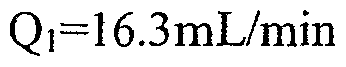 Q2=7.6mL/minThe starting flows are: Q 2 = 7.6mL / min
Qméiange =0.4mL/minQmeange = 0.4mL / min
Q4=4.82mL/minQ 4 = 4.82mL / min
ΔT=1.11minT = 1.11min
Les débits après régulation sont : Q,=16.3mL/minThe flow rates after regulation are: Q, = 16.3mL / min
Q2=7.84mL/minQ 2 = 7.84mL / min
Qméiange =0.4mL/minQmeange = 0.4mL / min
Q4=4.82mL/mmQ 4 = 4.82mL / mm
ΔT≈l. Hmin La troisième routine est ajoutée et modifie la quantité de charge injectée en fonction des analyses. Cette routine a pour conséquence de perturber le procédé et les première et deuxième routines permettent de s'adapter à ces perturbations. Le procédé est perturbé pour améliorer la quantité de produit que le procédé peut traiter. La modification de la quantité de charge prend en compte une fonction dépendante des puretés obtenues et des puretés cibles.ΔT≈l. Hmin The third routine is added and changes the amount of charge injected based on the analyzes. This routine has the effect of disrupting the process and the first and second routines allow to adapt to these disturbances. The process is disrupted to improve the amount of product that the process can process. The modification of the amount of charge takes into account a function dependent on the purities obtained and the target purities.
La figure 29 montre l'effet sur le raffinât et sur l'extrait du positionnement du point caractéristique alors que la quantité de mélange est modifiée. Le raffinât est en trait plein et l'extrait en pointillés.
Les débits de départ sont :
 Figure 29 shows the effect on the raffinate and the extract of the positioning of the characteristic point while the amount of mixture is changed. The raffinate is in full line and the extract dashed. The starting flows are:
Q2- 7.6mL/minQ 2 - 7.6mL / min
Qméiangc-0.52mL/min Q4=4.82mL/minQ i mé ANGC -0.52mL / min Q 4 = 4.82mL / min
ΔT=1.11minT = 1.11min
Le débit de charge de départ est supérieur au débit optimal. C'est à dire, que dans les conditions de départ, il est impossible d'obtenir un extrait et un raffinât avec une pureté de 99%. Les débits après régulation sont : Q,=16.3mL/minThe starting charge rate is greater than the optimal rate. That is, under the conditions of departure, it is impossible to obtain an extract and a raffinate with a purity of 99%. The flow rates after regulation are: Q, = 16.3mL / min
Q2=7.62mL/min
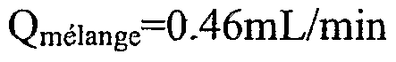 Q 2 = 7.62mL / min
Q4=4.82mL/minQ 4 = 4.82mL / min
ΔT=1.11min La troisième routine a adapté le débit de charge pour permettre d'atteindre les spécifications de 99% de pureté pour les différentes fractions.ΔT = 1.11min The third routine adapted the feed rate to achieve the 99% purity specifications for the different fractions.
La quatrième routine consiste en la régulation des zones 1 et 4. Cette régulation doit empêcher des pollutions venant des zones 1 et 4. Elle ne nécessite aucune analyse.The fourth routine consists of the regulation of zones 1 and 4. This regulation must prevent pollution from zones 1 and 4. It does not require any analysis.
Dans cet exemple, les débits en zone 1 et 4 à appliquer au cycle n+I sont calculés en utilisant les hypothèses et données suivantes :In this example, the rates in zone 1 and 4 to be applied to the n + I cycle are calculated using the following assumptions and data:
- les débits en zone 1 et 4 appliqués pendant les cycles n-1 et n.the flows in zones 1 and 4 applied during the cycles n-1 and n.
- les abscisses des points en zone 1 et en zone 4 des cycles n-1 et nthe abscissae of the points in zone 1 and in zone 4 of cycles n-1 and n
- l'hypothèse que les conditions d'élutions sont les mêmes pour les cycles n-1, n et n+1. La figure 30 montre le réglage du dispositif avec toutes les routines actives.- the assumption that the elution conditions are the same for the cycles n-1, n and n + 1. Figure 30 shows the device setting with all active routines.
L'extrait est en pointillés et le raffinât en trait plein.The extract is dotted and raffinate in solid line.
Les débits de départ sont :
 The starting flows are:
Q2=7.6mL/min
Q 2 = 7.6mL / min
Q4=4.82mL/minQ 4 = 4.82mL / min
ΔT≈l .1 1minΔT≈l .1 1min
Les débits après régulation sont :
 Q2=7.62mL/minFlow rates after regulation are: Q 2 = 7.62mL / min
Qmélange^^όmL/minQ mixture ^^ όmL / min
Q4=5.64mL/min ΔT=1.11minQ 4 = 5.64mL / min ΔT = 1.11min
Sur cet exemple, le débit de charge au démarrage est trop élevé pour pouvoir obtenir des puretés d'extrait et de raffinât au moins égales à 99%. Ainsi, pour que les puretés soient correctes, le débit de charge a été réduit. Le volume d'éluant a également été réduit sur cet exemple. En effet, celui-ci correspond à la différence entre les débits Qi et Q4 en zones 1 et 4. Qi étant diminué et Q4 augmenté, le débit d'éluant a diminué. Ainsi, le volume d'éluant utilisé sur un cycle a été réduit de 36%.In this example, the charge flow rate at startup is too high to obtain purities of extract and raffinate at least equal to 99%. Thus, for the purities to be correct, the charge flow rate has been reduced. The volume of eluent has also been reduced in this example. Indeed, it corresponds to the difference between the flow rates Qi and Q 4 in zones 1 and 4. Qi being decreased and Q 4 increased, the eluent flow rate decreased. Thus, the volume of eluent used on one cycle was reduced by 36%.
De façon plus générale, l'ensemble de ces routines a été testé et a montré son efficacité pour des conditions de débits et périodes initiales permettant d'obtenir des puretés initiales de raffinât et d'extrait supérieures à la pureté du mélange à séparer.More generally, all these routines have been tested and shown to be effective for flow conditions and initial periods to obtain initial purities of raffinate and extract greater than the purity of the mixture to be separated.
EXEMPLE 2 :EXAMPLE 2
Cet exemple illustre les différentes étapes du procédé de séparation sur un dispositif de séparation à injection continue de type SMB. La séparation choisie est l'exemple 2 du brevet US2002174769.This example illustrates the different steps of the separation process on an SMB type continuous injection separation device. The separation chosen is Example 2 of US2002174769.
Dans cet exemple, la variable spécifique utilisée correspond à la somme des concentrations de chacun des composés en mouvement dans le dispositif (ce qui correspond par exemple à la mesure de la densité, ou à la combinaison de plusieurs absorbance à différentes longueurs d'onde UV) Le point caractéristique utilisé est un extremum de l'historique constitué par le maximum du signal.In this example, the specific variable used is the sum of the concentrations of each of the compounds in motion in the device (which corresponds, for example, to the measurement of the density, or the combination of several absorbances at different UV wavelengths. ) The characteristic point used is an extremum of the history constituted by the maximum of the signal.
Dans cet exemple, la séparation est celle du fructose et du glucose sur une phase stationnaire de type Dowex 99 monosphère (350μm) ayant pour éluant de séparation l'eau à une température de 65°C. Dans ces conditions, l'isotherme d'adsorption est quasi-linéaire. Le système utilisé possède les caractéristiques suivantes :
 In this example, the separation is that of fructose and glucose on a stationary phase of Dowex 99 monosphere type (350 .mu.m) eluting with water at a temperature of 65.degree. Under these conditions, the adsorption isotherm is quasi-linear. The system used has the following characteristics:
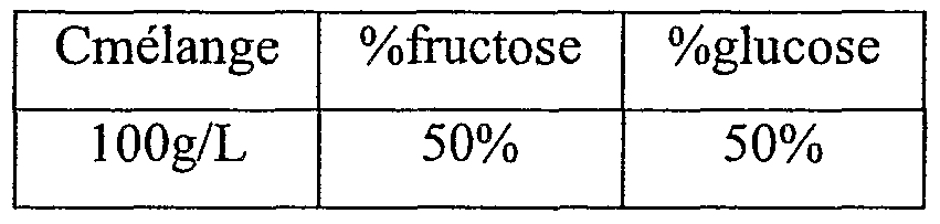
L'historique considéré est exprimé en temps réduit c'est à dire le temps divisé par le temps de cycle, il varie entre 0 et 1. L'origine de l'historique correspond au moment où l'éluant arrive à proximité du nœud d'observation.The history considered is expressed in reduced time ie the time divided by the cycle time, it varies between 0 and 1. The origin of the history corresponds to the moment when the eluent arrives close to the node of 'observation.
La position cible est fixée au point d'injection du mélange (c'est à dire à une abscisse de 0.56 sur l'historique, correspondant au milieu de la période d'injection). Le paramètre modifié est le débit en zone 2.The target position is fixed at the injection point of the mixture (that is to say at an abscissa of 0.56 on the history, corresponding to the middle of the injection period). The modified parameter is the flow in zone 2.
Le procédé démarre une fois le dispositif stabilisé avec les débits de démarrage, c'est à dire au cycle 11. Puis après régulation et stabilisation, une variation moyenne de 3.6% des temps de rétention est effectuée en augmentant d'une même valeur les constantes d'adsorption. La figure 31 représente l'évolution des puretés avec la régulation du dispositif puis la variation de la rétention (pour simuler une perturbation au cycle 50, flèche 58) avec la première routine active. Le raffinât est en trait plein et l'extrait en pointillés. On voit que la perturbation induit une diminution de la pureté de l'extrait, mais que le procédé permet ensuite une augmentation de la pureté de l'extrait. On règle la position du point caractéristique en une position cible fixe. Les débits de départ sont :
 Q2=73mL/minThe process starts once the device is stabilized with start-up flow rates, ie at cycle 11. Then after regulation and stabilization, an average variation of 3.6% of the retention times is carried out by increasing the constants by the same value. adsorption. FIG. 31 represents the evolution of the purities with the regulation of the device then the variation of the retention (to simulate a disturbance at cycle 50, arrow 58) with the first active routine. The raffinate is in full line and the extract dashed. It can be seen that the disturbance induces a decrease in the purity of the extract, but that the process then makes it possible to increase the purity of the extract. The position of the characteristic point is set to a fixed target position. The starting flows are: Q 2 = 73mL / min
Qmé!ange =8mL/minQ mé! Angel = 8 mL / min
Q4=57mL/min ΔT=7minQ 4 = 57ml / min T = 7min
Les débits après régulation sont :
 Flow rates after regulation are:
Q2=69.5mL/min
 Q4=57mL/min
ΔT=7minQ 2 = 69.5mL / min Q 4 = 57mL / min T = 7min
Q4=57mL/min
ΔT=7minQ 2 = 69.5mL / min Q 4 = 57mL / min T = 7min
Les débits après perturbation (flèche 58) en utilisant la régulation sont :
 The rates after disturbance (arrow 58) using the regulation are:
Q2=72.07mL/min Qmélange≈δmL/minQ 2 = 72.07mL / min Qm elang e≈δmL / min
Q4=57mL/minQ 4 = 57mL / min
ΔT=7minT = 7min
La figure 32 montre en comparaison l'évolution des puretés avec la régulation du dispositif, puis la simulation (flèche 60) de variation de la rétention au cycle 50 après avoir désactivé la première routine. Le raffinât est en trait plein et l'extrait en pointillés. On voit que la pureté de l'extrait diminue comme cela était le cas sur la figure 31 ; toutefois, à la différence de la figure 31, la pureté de l'extrait chute jusqu'à se stabiliser à une valeur inférieure à 96%.FIG. 32 shows in comparison the evolution of the purities with the regulation of the device, then the simulation (arrow 60) of variation of the retention at cycle 50 after having deactivated the first routine. The raffinate is in full line and the extract dashed. It can be seen that the purity of the extract decreases as was the case in FIG. 31; however, unlike FIG. 31, the purity of the extract drops until it stabilizes at less than 96%.
On peut constater que maintenir point caractéristique sur une position cible permet de maintenir les deux puretés à un niveau comparable à la situation précédant la perturbation (figure 31) ; sans la première routine, la pureté de l'extrait reste basse (figure 32).It can be seen that maintaining a characteristic point on a target position makes it possible to maintain the two purities at a level comparable to the situation preceding the disturbance (FIG. 31); without the first routine, the purity of the extract remains low (Figure 32).
Au cours de la deuxième routine, la position cible du maximum de signal varie afin d'ajuster les puretés à une valeur au moins égale à 99%. La figure 33 montre l'évolution des puretés avec le positionnement du point caractéristique avec une position cible définie par la deuxième routine. Le raffinât est en trait plein et l'extrait en pointillés.During the second routine, the target position of the signal maximum varies to adjust the purities to a value of at least 99%. Figure 33 shows the evolution of the purities with the positioning of the characteristic point with a target position defined by the second routine. The raffinate is in full line and the extract dashed.
Les débits de départ sont :
 Q2=73mL/min
 Q4=57mL/min ΔT=7minThe starting flows are: Q 2 = 73mL / min Q 4 = 57ml / min T = 7min
Dans cet exemple, les conditions de débit initiales mènent à une pureté de raffinât basse, qui va être compensée et régulée automatiquement pour mener aux débits après régulation suivants :
 Q2=69.7mL/min
Qméiaπge-8mL/minIn this example, the initial flow conditions lead to a low raffinate purity, which will be compensated and automatically regulated to lead to the following regulated flow rates: Q 2 = 69.7mL / min Q m éiaπge-8mL / min
Q2=69.7mL/min
Qméiaπge-8mL/minIn this example, the initial flow conditions lead to a low raffinate purity, which will be compensated and automatically regulated to lead to the following regulated flow rates: Q 2 = 69.7mL / min Q m éiaπge-8mL / min
Q4=57mL/minQ 4 = 57mL / min
ΔT=7minT = 7min
La modification de la position cible du point caractéristique prend en compte une fonction dépendante des puretés obtenues et des puretés cibles.The modification of the target position of the characteristic point takes into account a function depending on the purities obtained and the target purities.
Au cours de la troisième routine, le débit de mélange est optimisé afin que les puretés soient au moins égales à 99%.During the third routine, the mixing rate is optimized so that the purities are at least 99%.
La figure 34 montre l'évolution des puretés avec le positionnement du point caractéristique et Ia modification de la quantité de mélange injectée. Le raffinât est en trait plein et l'extrait en pointillés.FIG. 34 shows the evolution of the purities with the positioning of the characteristic point and the modification of the quantity of injected mixture. The raffinate is in full line and the extract dashed.
Les débits de départ sont :
 The starting flows are:
Q2=67mL/min
 Q4=57mL/minQ 2 = 67mL / min Q 4 = 57mL / min
ΔT=7minT = 7min
Les débits après régulation sont :
 Flow rates after regulation are:
Q2=68.24mL/min
 Q 2 = 68.24mL / min
Q4=57mL/minQ 4 = 57mL / min
ΔT=7minT = 7min
La modification de la quantité injectée est calculée par une fonction dépendante des puretés obtenues et des puretés cibles. La quatrième routine permet de déterminer les débits en zone 1 et 4 et d'éviter ainsi les fuites dans ces mêmes zones. La figure 35 montre l'évolution des puretés avec le procédé avec les quatre routines actives. Le raffinât est en trait plein et l'extrait en pointillés.The modification of the quantity injected is calculated by a function dependent on the purities obtained and the target purities. The fourth routine makes it possible to determine the flow rates in zones 1 and 4 and thus avoid leaks in these same zones. Figure 35 shows the evolution of purities with the method with the four active routines. The raffinate is in full line and the extract dashed.
Les débits de départ sont : Q,=1 15mL/minThe flow rates are: Q, = 1 15mL / min
Q2=67mL/min
 Q 2 = 67mL / min
Q4=57mL/min
ΔT=7minQ 4 = 57mL / min T = 7min
Les débits après régulation sont :
 Flow rates after regulation are:
Q2=68.24mL/min Qméiaπge=l 1 -21 mL/minQ 2 = 68.24mL / min Qmegeπge = l 1 -21 mL / min
Q4=59mL/minQ 4 = 59mL / min
ΔT=7minT = 7min
Au cours de cet exemple, le débit de charge de démarrage est trop élevé et il ne permet pas d'obtenir des puretés satisfaisantes. Afin que celles-ci soient au moins égales à 99%, le débit de charge a été réduit. De plus, la quatrième routine a permis une régulation du volume d'éluant. Celui-ci a été diminué de 20.7%.In this example, the startup charge rate is too high and it does not provide satisfactory purities. In order for these to be at least 99%, the load flow has been reduced. In addition, the fourth routine allowed regulation of the eluent volume. This has been decreased by 20.7%.
De façon plus générale, l'ensemble de ces routines a été testée et a montré son efficacité pour des conditions de débits et périodes initiales permettant d'obtenir des puretés initiales de raffinât et d'extrait supérieures à la pureté du mélange à séparer.More generally, all these routines have been tested and showed its effectiveness for flow conditions and initial periods to obtain initial purities of raffinate and extract greater than the purity of the mixture to be separated.
EXEMPLE 3 :EXAMPLE 3
Cet exemple illustre les différentes étapes du procédé de séparation sur un dispositif de séparation à injection discontinue de type CycloJet. Dans cet exemple, les routines de positionnement du point caractéristique, de définition du point cible, de modification de la quantité de mélange utilisent le signal d'un détecteur polarimétrique comme variable spécifique ; le point caractéristique utilisé est le point situé entre les collectes de raffinât et d'extrait où Ie signal du polarimètre est nul. La molécule de séparation est le 1,2,3,4-tetrahydro-l-naphtol. L'éluant de la séparation est un mélange Heptane/IP A/Acide trifluoroacérique (95/5/0.2 en volume). La phase utilisée pour la séparation est une phase Chiralpak AD de 20μm. Un modèle de la séparation a été déterminé. Il est noté qu'il ne s'agit pas de construire un modèle pour le réglage du procédé mais seulement pour simuler le dispositif.This example illustrates the different steps of the separation process on a discontinuous injection separation device of the CycloJet type. In this example, the characteristic point positioning, target point setting, and mix amount modification routines use the signal of a polarimetric detector as a specific variable; the characteristic point used is the point between the raffinate and extract collections where the polarimeter signal is zero. The separation molecule is 1,2,3,4-tetrahydro-1-naphthol. The eluent of the separation is a mixture Heptane / IP A / trifluoroaceric acid (95/5 / 0.2 by volume). The phase used for the separation is a Chiralpak AD phase of 20 μm. A model of separation has been determined. It is noted that it is not a question of constructing a model for the adjustment of the process but only to simulate the device.
La publication de O. Ludemann-Hombourger, R.M. Nicoud et M. Bailly dans Séparation Science and technology, 35(12), pp 1829-1862, 2000 donne tous les paramètres nécessaires à la simulation du procédé.The publication of O. Ludemann-Hombourger, R. M. Nicoud and M. Bailly in Separation Science and Technology, 35 (12), pp 1829-1862, 2000 gives all the parameters necessary for the simulation of the process.
La longueur de colonne considérée dans cet exemple est 50cm pour un diamètre interne de 1 cm. Le débit traversant la colonne pendant toute la séquence est noté QeI et
est égal à 25 mL/min. La durée du cycle CycloJet est notée ΔT. La séquence du cycle est exprimée comme suit : collecte du raffinât entre 0 et traf, injection à tinj, collecte de l'extrait entre text et ΔT. On définit ensuite les temps réduits : Xraf = traf/ΔT ; Xinj = tinj/ΔT, Xext = text/ΔT. Dans les exemples suivants, Xraf = 0.3, Xinj = 0.45 et Xext = 0.6.The column length considered in this example is 50 cm for an internal diameter of 1 cm. The flow rate passing through the column during the whole sequence is noted QeI and is equal to 25 mL / min. The duration of the CycloJet cycle is noted ΔT. The sequence of the cycle is expressed as follows: raffinate collection between 0 and traf, injection at tinj, collection of the extract between text and ΔT. The reduced times are then defined: Xraf = traf / ΔT; Xinj = tinj / ΔT, Xext = text / ΔT. In the following examples, Xraf = 0.3, Xinj = 0.45 and Xext = 0.6.
L'historique considéré est exprimé en temps réduit, c'est à dire le temps divisé par le temps de cycle, il varie entre 0 et 1. L'origine de l'historique correspond au début de la séquence de collecte du produit le mois retenu.The history considered is expressed in reduced time, ie the time divided by the cycle time, it varies between 0 and 1. The origin of the history corresponds to the beginning of the product collection sequence the month retained.
La première routine consiste à positionner le point caractéristique en une position cible (au point d'injection Xinj défini précédemment et correspondant à une abscisse de 0.45 sur l'historique). Cette routine ne nécessite pas la connaissance des puretés. Dans cet exemple, c'est la variation de la période du procédé qui permet cette régulation.The first routine consists of positioning the characteristic point in a target position (at the Xinj injection point defined above and corresponding to an abscissa of 0.45 on the history). This routine does not require the knowledge of purities. In this example, it is the variation of the period of the process that allows this regulation.
La figure 36 illustre l'évolution des puretés avec le réglage avec la première routine du procédé. Le raffinât est en trait plein et l'extrait en pointillés. Le réglage débute au cycle 21 (flèche 62) après stabilisation du dispositif avec les paramètres opératoires de démarrage. Puis au cycle 50, on réalise une variation de -4.8% des temps de rétention des produits (flèche 63). Les conditions de départ sont :Figure 36 illustrates the evolution of purities with the setting with the first routine of the process. The raffinate is in full line and the extract dashed. The setting starts at cycle 21 (arrow 62) after stabilization of the device with the starting operating parameters. Then in cycle 50, a variation of -4.8% of the product retention times (arrow 63) is realized. The starting conditions are:
ΔT=4.178minT = 4.178min
Vmj = 1.57mL Les conditions après régulation sont :Vmj = 1.57mL The conditions after regulation are:
ΔT = 3.983minΔT = 3.983min
Vinj = 1.57mLVinj = 1.57mL
La deuxième routine de définition de la position cible utilise des analyses de l'extrait et du raffinât afin de positionner au mieux la position cible de Ia première routine. La deuxième routine est ajoutée à la première routine. La deuxième routine utilise les puretés des extrait et raffinât. Au cours de cette routine, la position cible du point caractéristique est calculée de façon à ce que les puretés soient au moins égales à 99%.The second target position definition routine uses extract and raffinate analyzes to best position the target position of the first routine. The second routine is added to the first routine. The second routine uses the purities of the extract and raffinate. During this routine, the target position of the characteristic point is calculated so that the purities are at least 99%.
La modification de la position cible du point caractéristique prend en compte une fonction dépendante des puretés obtenues et des puretés cibles.The modification of the target position of the characteristic point takes into account a function depending on the purities obtained and the target purities.
La figure 37 montre l'évolution des puretés avec le procédé avec les première et deuxième routines actives. Le raffinât est en trait plein et l'extrait en pointillés. Les conditions de départ sont :
ΔT = 4.05minFigure 37 shows the evolution of purities with the method with the first and second active routines. The raffinate is in full line and the extract dashed. The starting conditions are: ΔT = 4.05min
Vinj = 1.57mLVinj = 1.57mL
Les première et deuxième routines du procédé sont mises en route au cycle 21 (flèche 64), au moment de la régulation, la position du point cible sur l'historique est égale à 0.517. Les conditions après régulation sont :The first and second routines of the process are started at cycle 21 (arrow 64), at the time of regulation, the position of the target point on the history is equal to 0.517. The conditions after regulation are:
ΔT = 4.17minΔT = 4.17min
Vinj = 1.57mLVinj = 1.57mL
Après mise en route des première et deuxième routines les puretés des deux fractions sont montées au dessus de 99.5% et la position du point caractéristique a été définie à 0.452.After starting the first and second routines, the purities of the two fractions were raised above 99.5% and the position of the characteristic point was set at 0.452.
La troisième routine modifie la quantité de mélange (ou charge) injecté en fonction des analyses. Elle est mise en œuvre par la connaissance des puretés des extrait et raffinât. Les spécifications de puretés dans ce cas sont de 99% sur les deux produits.The third routine modifies the amount of mixture (or charge) injected according to the analyzes. It is implemented by the knowledge of the purities of the extract and raffinate. The purity specifications in this case are 99% on both products.
Le calcul de la position cible se fait de la même manière qu'au cours de la deuxième routine.The calculation of the target position is done in the same way as during the second routine.
Le calcul de la quantité de charge injectée se fait à partir d'une fonction dépendante des puretés obtenues et des puretés cibles.The amount of charge injected is calculated from a function that is dependent on the purities obtained and the purities on the target.
La figure 38 montre l'évolution des puretés avec le procédé avec les première, deuxième et troisième routines actives. Le raffinât est en trait plein et l'extrait est en pointillés. Le procédé est mis en route au cycle 25 (flèche 68) Les conditions de départ sont :Figure 38 shows the evolution of purities with the method with the first, second and third active routines. The raffinate is in full line and the extract is dashed. The process is started in cycle 25 (arrow 68) The starting conditions are:
ΔT=4.147minT = 4.147min
Viηj = 3.96mLViηj = 3.96mL
Les conditions après régulation sont : ΔT = 3.968minThe conditions after regulation are: ΔT = 3.968min
Vinj = 4.88mLVinj = 4.88mL
La mise en œuvre des première, deuxième et troisième routines ont permis de passer à une situation où les deux puretés sont supérieures aux puretés cibles, en augmentant le volume injecté ainsi qu'en réduisant le temps de cycle, ceci permettant d'accroitre de 29% la quantité de mélange traitée par unité de temps.The implementation of the first, second and third routines allowed to move to a situation where the two purities are superior to the target purities, by increasing the volume injected as well as by reducing the cycle time, this making it possible to increase % the amount of mixture processed per unit of time.
La quatrième routine permet d'ajuster les collectes de raffinât et d'extrait.
Dans le cas général d'un procédé à accumulation incluant une collecte totale du produit le plus retenu dans sa séquence, la régulation de cette étape est effectuée lorsque par exemple il y a une différence de la position cible et de la position du point caractéristique de la désorption en modifiant la durée de l'étape de collecte. On peut noter que la modification de la durée d'étape de collecte correspond à la modification du volume de phase mobile associé à la désorption du produit le plus retenu.The fourth routine adjusts the raffinate and extract collections. In the general case of a storage method including a total collection of the most retained product in its sequence, the regulation of this step is carried out when for example there is a difference in the target position and the position of the characteristic point of the desorption by changing the duration of the collection step. It may be noted that the modification of the collection step duration corresponds to the change in the mobile phase volume associated with the desorption of the most selected product.
Dans le cas du présent exemple CycloJet, il est considéré que le point caractéristique de la désorption est désigné par un seuil Y4.1 * en abscisse de signal UV situé entre le début de la collecte d'extrait et la fin d'injection d'éluant. Avec une collecte d'extrait commençant à partir de 60% de la période (Xext =In the case of the present CycloJet example, it is considered that the characteristic point of the desorption is designated by a threshold Y4.1 * in abscissa of UV signal situated between the beginning of the collection of extract and the end of injection of eluent. With an extract collection starting from 60% of the period (Xext =
0.6) la position du point caractéristique est obtenue à Xn = 0.8. (figure 39)0.6) the position of the characteristic point is obtained at Xn = 0.8. (Figure 39)
Définissons à X*= 0.9 la position cible, on constate un écart de 0.1 que l'on peut réduire en modifiant la durée de l'étape de collecte d'extrait. Par exemple en répercutant cet écart sur la position de début de collecte d'extrait. Xext passe alors de 0.6 à 0.7 (figure 40).Let us define at X * = 0.9 the target position, there is a difference of 0.1 that can be reduced by modifying the duration of the extract collection step. For example by passing this discrepancy to the starting position of extract collection. Xext then goes from 0.6 to 0.7 (Figure 40).
Dans le cas général d'un procédé à accumulation incluant une collecte totale du produit le moins retenu dans sa séquence, la régulation de cette étape est effectuée lorsque par exemple il y a une différence la position cible et la position du point caractéristique de l'adsorption en modifiant la durée de l'étape de collecte. Notons que la modification de la durée d'étape de collecte correspond à la modification du volume de phase mobile associé à la collecte du produit le moins retenu.In the general case of a storage method including a total collection of the least retained product in its sequence, the regulation of this step is carried out when, for example, there is a difference between the target position and the position of the characteristic point of the adsorption by changing the duration of the collection step. It should be noted that the modification of the collection step duration corresponds to the modification of the mobile phase volume associated with the collection of the least retained product.
Dans le cas de présent exemple CycloJet, il est considéré que le point caractéristique de l'adsorption est désigné par un seuil Y4.2* de signal UV situé entre le début de l'injection d'éluant et la fin de la collecte de raffinât. Avec une collecte de raffinât se terminant à partir de 30% de la période (Xraf =In the case of the present example CycloJet, it is considered that the characteristic point of the adsorption is designated by a threshold Y4.2 * of UV signal situated between the beginning of the eluent injection and the end of the raffinate collection. . With a raffinate collection ending from 30% of the period (Xraf =
0.3) la position du point caractéristique est obtenue à Xn = 0.2. (figure 41)0.3) the position of the characteristic point is obtained at Xn = 0.2. (Figure 41)
Définissons à X*= 0.1 la position cible, on constate un écart de -0.1 que l'on peut réduire en modifiant la durée de l'étape de collecte de raffinât. Par exemple on répercute cet écart sur la position de début de collecte d'extrait. Xraf passe alors de 0.3 à 0.2 (figure 42).Let us define at X * = 0.1 the target position, there is a difference of -0.1 that can be reduced by modifying the duration of the raffinate collection step. For example, this difference is reflected on the starting position of collection of extract. Xraf then goes from 0.3 to 0.2 (Figure 42).
Lorsque l'on collecte de l'extrait ou du raffinât en CycloJet, on injecte de l'éluant, en réduisant les durées des étapes de collectes d'extrait et de raffinât, on a consécutivement réduit la consommation d'éluant.
Dans ce dernier cas, la quatrième routine a permis une régulation de la quantité d'éluant, avant régulation, l'éluant était injecté pendant 70% de la séquence du cycle, après régulation l'éluant est injecté pendant 50% du cycle. Il s'agit d'une réduction de 28% de la consommation d'éluant. D'une façon plus générale, l'ensemble de ces routines a été testée et a montré son efficacité pour des conditions de débits et périodes initiales permettant d'obtenir des puretés initiales de raffinât et d'extrait supérieures à la pureté de du mélange à séparer.When CycloJet extract or raffinate is collected, eluent is injected, reducing the times of the extract and raffinate collection steps, the consumption of eluent is consecutively reduced. In the latter case, the fourth routine allowed a regulation of the amount of eluent, before regulation, the eluent was injected during 70% of the cycle sequence, after regulation the eluent is injected during 50% of the cycle. This is a 28% reduction in eluent consumption. In a more general manner, all these routines have been tested and showed its effectiveness for flow conditions and initial periods making it possible to obtain initial purities of raffinate and extract greater than the purity of the mixture. to separate.
EXEMPLE 4 Cet exemple illustre les différentes étapes du procédé de séparation sur un procédé de séparation à injection continue VariCol. La séparation choisie est celle des isomères du mélange racémique de la tétralone décrit dans WO99/57089 - ayant pour titre Process for the production of enantiomerically pure or optically enriched sertralone- tetralone using continuous chromatography. Dans cet exemple, les routines de positionnement du point caractéristique dans la zone de séparation, de définition du point cible, de modification de la quantité de mélange utilisent le signal d'un détecteur polarimétrique comme variable spécifique ; le point caractéristique utilisé est le point situé entre les collectes de raffinât et d'extrait où le signal du polarimètre est nul — il n'est donc pas nécessaire pour utiliser l'invention d'effectuer un étalonnage du détecteur puisque ce ne sont pas les valeurs des concentrations qui sont recherchées mais un point caractéristique du signal.EXAMPLE 4 This example illustrates the various steps of the separation process on a VariCol continuous injection separation process. The separation chosen is that of the isomers of the racemic mixture of tetralone described in WO99 / 57089 - entitled Process for the production of enantiomerically pure or optically enriched sertralone-tetralone using continuous chromatography. In this example, the positioning routines of the characteristic point in the separation zone, the target point definition, the change of the mixing amount use the signal of a polarimetric detector as a specific variable; the characteristic point used is the point between the raffinate and extract collections where the polarimeter signal is zero - it is therefore not necessary to use the invention to carry out a calibration of the detector since it is not the values of the concentrations which are sought but a characteristic point of the signal.
Le mélange racémique peut être séparé sur une phase Chiralpak AD (Chiral Technologies Europe) avec un diamètre de particule moyen de 20μm. L'éluant servant à la séparation est composé d'acétonitrile pur. La séparation s'effectue à la température de 25°C.The racemic mixture can be separated on a Chiralpak AD phase (Chiral Technologies Europe) with a mean particle diameter of 20 μm. The eluent used for the separation is composed of pure acetonitrile. The separation is carried out at a temperature of 25 ° C.
Le dispositif expérimental utilisé est un VariCol 5 colonnes de diamètre 5 cm et de longueur 1 1.5 cm. Dans le cas de cette séparation, les colonnes se répartissent de la manière suivante :The experimental device used is a VariCol 5 columns with a diameter of 5 cm and a length of 1.5 cm. In the case of this separation, the columns are distributed as follows:

La charge utilisée est à une concentration de 13g/L. Les objectifs sont d'obtenir le produit le plus retenu, l'extrait, à une pureté de 90% et le produit le moins retenu, le raffinât, à une pureté de 98.5%. Dans cet exemple, les trois premières routines du contrôle sont activées, soit :The load used is at a concentration of 13g / L. The objectives are to obtain the most selected product, the extract, at a purity of 90% and the least retained product, raffinate, at a purity of 98.5%. In this example, the first three control routines are enabled, which is:
" La première routine qui consiste à positionner un point caractéristique de la zone de séparation en une position cible. Cette première routine n'a besoin d'aucune analyse de pureté."The first routine that consists of positioning a characteristic point of the separation zone in a target position This first routine needs no purity analysis.
• La deuxième routine de définition de la position cible utilisant les puretés des lignes d'extrait et de raffinât qui positionne au mieux la position cible de la première étape. Au cours de cette routine, la position cible est modifiée de façon à ce que les puretés des produits extrait et raffinât correspondent aux spécifications.• The second routine for defining the target position using the purities of the extract and raffinate lines which best positions the target position of the first step. During this routine, the target position is changed so that the purities of the extracted and raffinate products correspond to the specifications.
" La troisième routine qui modifie la quantité de charge injectée est modifiée en fonction des analyses précises des puretés de façon à ce que les puretés des produits extrait et raffinât soient supérieures ou égales aux spécifications.The third routine, which changes the amount of feed injected, is modified according to the precise analyzes of the purities so that the purities of the extracted and refined products are greater than or equal to the specifications.
Dans cet exemple, la durée des analyses de l'extrait et du raffinât implique un retard de 3 cycles sur la connaissance des puretés. Ainsi, la première routine de la régulation est effectuée tous les cycles tandis que les analyses précises des puretés extrait et raffinât sont disponibles tous les 3 cycles. Les actions des étapes 2 et 3 sont modifiées dès que des mesures de puretés précises sont disponibles, soit tous les 3 cycles.
Par exemple, extrait et raffinât sont collectés pendant la durée du cycle 10, et analysés pendant les cycles 1 1 et 12, les valeurs des puretés sont donc disponibles en fin de cycle 12. Au cycle 13, il est possible d'avoir une modification de l'action sur la consigne de position du point caractéristique et sur le débit de charge. Cette action au cycle 13 est basée sur la valeur des puretés du cycle 10. Le procédé est donc capable de réagir lorsqu'il y a à la fois un retard et un espacement des analyses précises des extrait et raffinât.In this example, the duration of the analyzes of the extract and raffinate involves a delay of 3 cycles on the knowledge of the purities. Thus, the first routine of the regulation is carried out every cycle while the precise analyzes of the extracted and raffinate purities are available every 3 cycles. The actions in steps 2 and 3 are modified as soon as precise purity measurements are available, ie every 3 cycles. For example, extract and raffinate are collected during the cycle 10, and analyzed during the cycles 1 1 and 12, the purity values are therefore available at the end of cycle 12. In cycle 13, it is possible to have a modification the action on the position of the characteristic point and on the load flow. This action at cycle 13 is based on the purity value of cycle 10. The process is therefore able to react when there is both a delay and a spacing of the precise analyzes of the extract and raffinate.
La régulation est mise en route au démarrage de l'unité avec les débits suivants :
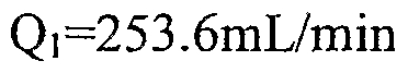 Q2=197.9mL/minThe regulation is started at the start of the unit with the following flows: Q 2 = 197.9mL / min
Qméiange =8mL/min Q4=152.6mL/min T=I .4minQmean = 8mL / min Q 4 = 152.6mL / min T = 1 .4min
Où Qi1 Q2i Qméiange et Q4 sont respectivement les débits dans les zone I, zone II, le débit de mélange à traiter et le débit dans la zone IV, ces zones sont définies d'une façon identique pour les procédés SMB et VariCol et représentées sur la figure 1.Where Qi 1 Q 2i Qméi an g e and Q 4 are respectively the flow rates in zone I, zone II, the mixture flow to be treated and the flow rate in zone IV, these areas are defined in a manner identical to the methods SMB and VariCol and shown in FIG.
Ces débits initiaux mènent à une pureté du raffinât proche de 79% et une pureté d'extrait de 99%.These initial flow rates lead to a purity of the raffinate close to 79% and an extract purity of 99%.
Les débits après régulation (c'est à dire pour une pureté de raffinât de 98%, une pureté d'extrait de 90% et un débit de charge optimisé) sont : Q i =253.6mL/min Q2=177.5mL/min Qméiange =15.2mL/min Q4=I 52.6mL/min ΔT=1.4minThe flow rates after regulation (that is to say for a purity of raffinate of 98%, a purity of extract of 90% and an optimized flow of load) are: Q i = 253.6mL / min Q 2 = 177.5mL / min Qmean = 15.2mL / min Q 4 = I 52.6mL / min ΔT = 1.4min
La figure 43 représente l'évolution des puretés d'extrait (carrés), de raffinât (triangles) et du débit de charge (trait plein en gras) au cours du procédé de séparation. La figure 44 représente l'évolution de la position du point caractéristique (trait plein gras) ainsi que de sa position de consigne (trait plein fin). Sur la figure 43, on observe que la pureté du raffinât est rapidement améliorée et amenée au dessus de 98%. Cette action est due aux actions combinées des première et deuxième routines qui ont éloigné
le point caractéristique de la ligne de raffinât, en passant d'une abscisse de 0.64 à une abscisse de 0.42.Figure 43 shows the evolution of extract (squares), raffinate (triangles) and charge flow (full-fat lines) purities during the separation process. Figure 44 shows the evolution of the position of the characteristic point (full bold line) as well as its set position (solid line end). In FIG. 43, it is observed that the purity of the raffinate is rapidly improved and brought to above 98%. This action is due to the combined actions of the first and second routines that have moved away the characteristic point of the raffinate line, from an abscissa of 0.64 to an abscissa of 0.42.
Au cycle 10, les deux produits sont au dessus des spécifications de puretés et le débit de charge peut donc être augmenté. Au cycle 40, les puretés sont inférieures aux spécifications aussi le débit de charge est réajusté à l'aide de la troisième routine.In Cycle 10, both products are above purity specifications and the charge rate can be increased. At cycle 40, the purities are lower than the specifications and the charge rate is readjusted using the third routine.
Dans cet exemple, la pureté du raffinât est fortement dégradée au démarrage de l'unité et celle-ci est ramenée aux spécifications en une dizaine de cycles. La pureté d'extrait est ajustée à 90% en une quarantaine de cycles. Le débit de charge est régulé (passage de 8ml/min à 15.2ml/min) en une soixantaine de cycle.In this example, the purity of the raffinate is strongly degraded at the start of the unit and it is reduced to specifications in about ten cycles. The purity of the extract is adjusted to 90% in about forty cycles. The charge rate is regulated (from 8ml / min to 15.2ml / min) in about 60 cycles.
EXEMPLE 5EXAMPLE 5
Cet exemple illustre les différentes étapes du procédé de séparation sur un procédé de séparation à injection continue SMB.This example illustrates the different steps of the separation process on an SMB continuous injection separation process.
La séparation choisie est l'exemple du brevet US2002174769.The separation chosen is the example of US2002174769.
Dans cet exemple, la variable spécifique utilisée par la première routine correspond à la différence des concentrations de chacun des composés en mouvement dans le dispositif le point caractéristique associé est l'annulation du signal dans la zone de séparation. La variable spécifique utilisée par la quatrième routine est la somme des concentrations, les points caractéristiques associés sont des seuils relatifs. Dans cet exemple, les variables spécifiques et les points caractéristiques associés ne nécessitent pas de mesure précise de concentrations, ce qui autorise de ne pas étalonner les détecteurs donnant les variables spécifiques.In this example, the specific variable used by the first routine corresponds to the difference in the concentrations of each of the moving compounds in the device. The associated characteristic point is the cancellation of the signal in the separation zone. The specific variable used by the fourth routine is the sum of the concentrations, the associated characteristic points are relative thresholds. In this example, the specific variables and the associated characteristic points do not require precise measurement of concentrations, which makes it possible not to calibrate the detectors giving the specific variables.
Dans cet exemple, la séparation est celle du fructose et du glucose sur une phase stationnaire de type Dowex 99 monosphère (350μm) ayant pour éluant de séparation l'eau à une température de 65°C. Dans ces conditions, l'isotherme d'adsorption est quasi-linéaire.In this example, the separation is that of fructose and glucose on a stationary phase of Dowex 99 monosphere type (350 .mu.m) eluting with water at a temperature of 65.degree. Under these conditions, the adsorption isotherm is quasi-linear.
Le système utilisé possède les caractéristiques suivantes :The system used has the following characteristics:

Dans cet exemple, les quatre routines du contrôle sont activées, soit : " La première routine qui consiste à positionner un point caractéristique de la zone de séparation en une position cible. Cette première routine n'a besoin d'aucune analyse de pureté.In this example, the four routines of the control are activated, namely: "The first routine which consists in positioning a characteristic point of the separation zone in a target position This first routine needs no purity analysis.
" La deuxième routine de définition de la position cible utilisant les puretés des lignes d'extrait et de raffinât qui positionne au mieux la position cible de la première étape. Au cours de cette routine, la position cible est modifiée de façon à ce que les puretés des produits extrait et raffinât correspondent aux spécifications."The second routine of setting the target position using the purities of the extract and raffinate lines which best positions the target position of the first step During this routine, the target position is modified so that the purities of the extract and raffinate products correspond to the specifications.
• La troisième routine qui modifie la quantité de charge injectée est modifiée en fonction des analyses précises des puretés de façon à ce que les puretés des produits extrait et raffinât soient supérieures ou égales aux spécifications• The third routine that modifies the amount of feedstock injected is modified based on accurate purity analyzes so that the purities of the extracted and refined products are greater than or equal to the specifications
• La quatrième routine qui consiste à positionner les points caractéristiques de chacune des zones I et IV en une position cible. Elle permet de régler ces mêmes zones avec comme conséquence la modification du débit d'éluant.• The fourth routine which consists in positioning the characteristic points of each of the zones I and IV in a target position. It makes it possible to adjust these same zones with the consequence of modifying the eluent flow rate.
Le point caractéristique en zone I doit être situé à une abscisse cible définie en milieu de la zone I et la valeur seuil choisie est déterminée à 1 % du maximum du signalThe characteristic point in zone I must be located at a target abscissa defined in the middle of zone I and the chosen threshold value is determined at 1% of the maximum of the signal
UV. U en est de même en zone IV pour une abscisse cible située en zone IV. La valeur seuil est donc flottante en fonction des valeurs maximum et minimum de la variable spécifique correspondant à la somme des deux concentrations.UV. It is the same in zone IV for a target abscissa located in zone IV. The threshold value is therefore floating according to the maximum and minimum values of the specific variable corresponding to the sum of the two concentrations.
Les puretés sont calculées en effectuant une moyenne sur un cycle des compositions extrait et raffinât. Dans cet exemple numérique, un temps de retard de 3 cycles sur la connaissance des puretés a été ajouté.The purities are calculated by averaging one cycle of the extract and raffinate compositions. In this numerical example, a delay time of 3 cycles on purity knowledge was added.
La régulation est mise en route au démarrage de l'unité avec les débits suivants :
The regulation is started at the start of the unit with the following flows:
Q2=67mL/min Qméiange =13.76mL/min Q4=57mL/min
T=7minQ 2 = 67mL / min Qméiange = 13.76mL / min Q 4 = 57ml / min T = 7min
Où Qi F Q2> Qméiange et Q4 sont respectivement les débits dans les zone I, zone II, le débit de mélange à traiter et le débit dans la zone IV, ces zones sont définies d'une façon identique pour les procédés SMB et VariCol et représentées sur la figure 1. Ces débits mènent à une pureté du raffinât proche de 97% et une pureté d'extrait de 97%.Where Qi F Q 2> Qmeange and Q 4 are respectively the flow rates in zone I, zone II, the mixing rate to be treated and the flow rate in zone IV, these zones are defined in the same way for the SMB processes and VariCol and shown in Figure 1. These flow rates lead to a raffinate purity close to 97% and an extract purity of 97%.
Les débits après régulation (c'est à dire pour une pureté de raffinât de 99%, une pureté d'extrait de 99% et des débits de charge et d'éluant optimisés) sont :
 Q2=68.2mL/minThe flow rates after regulation (that is to say for a raffinate purity of 99%, a purity of 99% extract and optimized charge and eluent flow rates) are: Q 2 = 68.2mL / min
Qméiange =1 1.25mL/min Q4=58.2mL/min ΔT= 1.4minQméiange 1 = 1.25ml / min Q 4 = 58.2mL / min T = 1.4min
La figure 45 représente l'évolution des puretés d'extrait (carré), de raffinât (triangle) et du débit de charge (trait plein en gras) au cours du procédé de séparation. La figure 46 représente l'évolution du débit d'éluant au cours de la séparation.Figure 45 shows the evolution of extract (square), raffinate (triangle) and charge flow (full fat) purities during the separation process. Figure 46 shows the evolution of the eluent flow during separation.
Au cours de cet exemple, le débit de charge de démarrage est trop élevé et il ne permet pas d'obtenir des puretés satisfaisantes. Afin que celles-ci soient au moins égales à 99%, le débit de charge a été réduit. On observe une bonne régulation malgré la présence de 3 cycles de retard sur la connaissance des puretés. De plus, celle-ci est aussi rapide qu'en l'absence de cycles de retard (cf figure 35).In this example, the startup charge rate is too high and it does not provide satisfactory purities. In order for these to be at least 99%, the load flow has been reduced. Good regulation is observed despite the presence of 3 cycles of delay on the knowledge of purities. Moreover, it is as fast as there are no delay cycles (see FIG. 35).
La quatrième routine a permis une régulation du volume d'éluant en le diminuant de 37.9%.The fourth routine allowed a regulation of the eluent volume by decreasing it by 37.9%.
EXEMPLE 6 :EXAMPLE 6
Cet exemple illustre l'effet de la première routine de contrôle sur un procédé de séparation à injection discontinue de type celui décrit dans la demande FR 2 889 077.This example illustrates the effect of the first control routine on a discontinuous injection separation process of the type described in application FR 2 889 077.
Dans cet exemple, la routine de positionnement du point caractéristique utilise le signal d'un détecteur polarimétrique comme variable spécifique ; le point caractéristique utilisé est le point situé entre les collectes de raffinât et d'extrait où le signal du polarimètre est nul.In this example, the characteristic point positioning routine uses the signal of a polarimetric detector as a specific variable; the characteristic point used is the point situated between the raffinate and extract collections where the polarimeter signal is zero.
La molécule de séparation est le 1,2,3,4-tetrahydro-l-naphtoI. L'éluant de la séparation est un mélange Heptane/IP A/Acide trifluoroacétique (95/5/0.2 en volume).
La phase utilisée pour la séparation est une phase Chiralpak AD de 20μm. Un modèle de la séparation a été déterminé afin de simuler le dispositif.The separation molecule is 1,2,3,4-tetrahydro-1-naphthol. The eluent of the separation is a mixture Heptane / IP A / trifluoroacetic acid (95/5 / 0.2 by volume). The phase used for the separation is a Chiralpak AD phase of 20 μm. A model of the separation was determined in order to simulate the device.
La publication de O. Ludemann-Hombourger, R.M. Nicoud et M. Bailly dans Séparation Science and Technology, 35 (12), pp 1829-1862, 2000 donne tous les paramètres nécessaires à la simulation du procédé.The publication of O. Ludemann-Hombourger, R. M. Nicoud and M. Bailly in Separation Science and Technology, 35 (12), pp 1829-1862, 2000 gives all the parameters necessary for the simulation of the process.
Les grandeurs utilisées pour la simulation sont :The quantities used for the simulation are:
• 2 colonnes de 1 cm de diamètre interne et 20 cm de long ;• 2 columns of 1 cm internal diameter and 20 cm long;
• la température est de 25°C• the temperature is 25 ° C
• le débit d'éluant de 22 mL/min, sauf lorsque la charge est injectée, le débit d ' éluant est alors nul• the eluent flow rate of 22 mL / min, except when the feed is injected, the eluent flow is then zero
• une charge composée du racémique dissous dans Péluant à une concentration de 20g/L ; cette charge est injectée à un débit de 15.7 mL/min pendant 0.1min au début de chaque période, en entrée de la seconde colonne lors de la première période et en entrée de la première colonne lors de la seconde période.• a compound charge of racemic dissolved in eluant at a concentration of 20g / L; this charge is injected at a rate of 15.7 ml / min for 0.1 min at the beginning of each period, at the entry of the second column during the first period and at the entry of the first column during the second period.
• la période est ΔT, la durée du cycle est de 2 périodes soit 2.ΔT. On simule la séquence de la figure 47, répétée de façon cyclique.• the period is ΔT, the duration of the cycle is 2 periods or 2.ΔT. The sequence of FIG. 47 is repeated cyclically.
Dans cet exemple, seule la première routine est activée. Le détecteur utilisé au nœud d'observation 24 est situé en sortie de seconde colonne, correspond à un polarimètre renvoyant une variable spécifique représentative de la différence des deux concentrations. Le point caractéristique 28 est le point de la zone de séparation où le signal est nul. La première routine consiste à positionner le point caractéristique 28 en une position cible 32, par exemple à l'abscisse 0,9. Cette routine ne nécessite pas la connaissance des puretés. Les figures 48 et 49 montre respectivement le signal polarimétrique en trait gras au démarrage de l'unité et après régulation.In this example, only the first routine is enabled. The detector used at the observation node 24 is located at the output of the second column, corresponds to a polarimeter returning a specific variable representative of the difference of the two concentrations. The characteristic point 28 is the point of the separation zone where the signal is zero. The first routine consists in positioning the characteristic point 28 in a target position 32, for example at the abscissa 0.9. This routine does not require the knowledge of purities. Figures 48 and 49 respectively show the polarimetric signal in bold lines at the start of the unit and after regulation.
Les conditions de départ sont : ΔT=1.76min, la position du point caractéristique 28 sur la figure 48 est est supérieure à 1, ce qui implique un « retard » que la première routine va corriger en augmentant le volume de phase mobile permettant, sur un cycle de déplacer le point caractéristique. Dans cet exemple, c'est la variation de la période du procédé qui permet cette régulation : à débit constant, augmenter le volume de phase mobile permettant sur un cycle de déplacer le point caractéristique résulte en une
augmentation de la période. Sur la figure 49, le point caractéristique 28 est au point 32 (par exemple 0,9).The starting conditions are: ΔT = 1.76min, the position of the characteristic point 28 in FIG. 48 is greater than 1, which implies a "delay" that the first routine will correct by increasing the mobile phase volume allowing, on a cycle to move the characteristic point. In this example, it is the variation of the period of the process which allows this regulation: at constant flow, increasing the volume of mobile phase allowing on a cycle to move the characteristic point results in a increase of the period. In Fig. 49, the characteristic point 28 is at point 32 (e.g., 0.9).
Les conditions après régulation, c'est à dire positionnement du point caractéristique au point d'abscisse 0,9 , sont : ΔT≈l.82min. Cet exemple illustre l'intérêt de la première routine. Une régulation d'un point caractéristique en une position cible n'exige pas d'étalonnage rigoureux ni de mesure précise de pureté, et peut se faire d'un cycle à l'autre. La position cible optimale peut ainsi être définie par l'utilisateur du procédé ou de façon automatique par l'ajout d'un dispositif de mesure des puretés des collectes par exemple moyennées sur un cycle et l'utilisation des routines 2 et 3 de l'invention.The conditions after regulation, ie positioning of the characteristic point at the abscissa point 0.9, are: ΔT≈l.82min. This example illustrates the interest of the first routine. Control of a characteristic point at a target position does not require rigorous calibration or accurate measurement of purity, and can be done from cycle to cycle. The optimal target position can thus be defined by the user of the process or automatically by adding a device for measuring the purities of the collections, for example averaged over a cycle, and the use of the routines 2 and 3 of the invention.
Les exemples illustrent que l'invention s'applique à des procédés continus ou discontinus, en contrôlant le volume de phase mobile qui permet de positionner un point caractéristique, ce en modifiant le débit de fluide, ou en changeant la durée pendant laquelle on applique un débit de phase mobile dans le système, naturellement une combinaison des deux approches est possible.The examples illustrate that the invention applies to continuous or discontinuous processes, by controlling the mobile phase volume which makes it possible to position a characteristic point, by modifying the fluid flow, or by changing the duration during which one applies a mobile phase flow in the system, naturally a combination of both approaches is possible.
Un procédé multi-colonnes de type SSMB est composé d'un ensemble de périodes (intervalle de temps séparant le déplacement des lignes d'éluant, charge, extrait et raffinât). Chacune de ces périodes est un ensemble de sous séquences. La modification du volume de phase mobile permettant de positionner un point caractéristique peut alors se faire par modification du débit ou en changeant la durée d'application du débit sur la durée d'une ou plusieurs des séquences qui composent Ia période.A multi-column method of the SSMB type is composed of a set of periods (time interval separating the displacement of the eluent, charge, extract and raffinate lines). Each of these periods is a set of sub-sequences. The change of the mobile phase volume to position a characteristic point can then be done by changing the rate or changing the duration of application of the flow over the duration of one or more of the sequences that make up the period.
EXEMPLE 7 Cet exemple illustre un point caractéristique utilisable dans la zone de séparation appliquable préférentiellement sur un procédé CycloJet ou sur un procédé similaire au procédé de l'exemple 6.EXAMPLE 7 This example illustrates a characteristic point that can be used in the separation zone preferentially applicable to a CycloJet process or to a process similar to the method of Example 6.
La figure 19 montre un historique de signal d'un détecteur UV que l'on peut obtenir sur un procédé CycloJet. La figure 50 montre l'intégration dans le temps du signal fourni par le détecteur UV montré figure 19 - en ligne grise épaisse (non droite).Figure 19 shows a signal history of a UV detector that can be obtained on a CycloJet process. Figure 50 shows the time integration of the signal provided by the UV detector shown in Figure 19 - thick gray line (not right).
La figure 50 montre un signal UV intégré dans le temps sur un historique procédé Cyclojet.
Le signal de la figure 50 présente des hauteurs minimum Hmin et maximum Hmax en début et fin de cycle. En fin de collecte 29, la hauteur est Hj et en début de collecte 30, la hauteur du signal est H2.Figure 50 shows a UV signal integrated over time on a historic Cyclojet process. The signal of FIG. 50 has minimum heights Hmin and maximum Hmax at the beginning and end of the cycle. At the end of collection 29, the height is Hj and at the beginning of collection 30, the height of the signal is H 2 .
Une première droite en pointillés est tracée entre : « un point d'abscisse fin de collecte 29 et hauteur HminA first dashed line is drawn between: "a point of abscissa end of collection 29 and height Hmin
• un point d'abscisse début de collecte 30 et hauteur Hmax Une seconde droite en trait plein est tracée entre :• a point of abscissa beginning of collection 30 and height Hmax A second line in full line is drawn between:
• un point d'abscisse fin de collecte 29 et hauteur Hi• a point of abscissa end of collection 29 and height Hi
• un point d'abscisse début de collecte 30 et hauteur H2 L'intersection des deux droites ainsi obtenues est un point caractéristique dont l'abscisse ou position peut être régulée selon l'invention.A point of abscissa beginning of collection 30 and height H 2 The intersection of the two lines thus obtained is a characteristic point whose abscissa or position can be regulated according to the invention.
Dans cet exemple, il n'est pas nécessaire de connaître avec précision les concentrations des espèces, ce que le détecteur UV ne permet pas. Il est donc possible de considérer comme variable spécifique le signal en lui même mais également une transformation de ce signal comme par exemple une intégration.
In this example, it is not necessary to know exactly the concentrations of the species, which the UV detector does not allow. It is therefore possible to consider as a specific variable the signal itself but also a transformation of this signal such as an integration.
Claims
1. Procédé de séparation de fraction d'un mélange dans un dispositif de chromatographie ayant - une ou plusieurs colonnes (12) en boucle, une phase mobile en circulation déplaçant les fractions du mélange à séparer dans ladite boucle,1. Process for fraction separation of a mixture in a chromatography device having one or more columns (12) in a loop, a circulating mobile phase displacing the fractions of the mixture to be separated in said loop,
- des points d'injection de mélange (14) et d'éluant (18),mixing injection points (14) and eluent (18),
- des points de collectes de fractions (16, 20),fraction collection points (16, 20),
- des organes de séquençage des points d'injection et de collecte, le procédé comprenant des étapes de collecte des fractions, d'injection de mélange entre deux collectes successives dans l'intervalle où les fractions du mélange sortent de la ou les colonnes et sont envoyées vers l'entrée suivante ; le procédé étant caractérisé en ce qu'il comprend en outre les étapes de :sequencing organs of the injection and collection points, the method comprising steps of collecting the fractions, mixing injection between two successive collections in the interval where the fractions of the mixture leave the column or columns and are sent to the next entry; the method being characterized in that it further comprises the steps of:
- contrôle en un nœud (24) du dispositif, de l'historique d'une variable spécifique des fractions du mélange à séparer,control in a node (24) of the device, of the history of a specific variable of the fractions of the mixture to be separated,
- détection d'un point caractéristique (28) de l'historique, le point caractéristique étant entre deux étapes successives de collecte de fraction,detecting a characteristic point (28) of the history, the characteristic point being between two successive fraction collection steps,
- comparaison de la position du point caractéristique par rapport à une position cible (32), - réglage de la quantité de la phase mobile modifiant Ia position du point caractéristique pour faire coïncider la position du point caractéristique avec la position cible.- comparing the position of the characteristic point with respect to a target position (32), - adjusting the amount of the mobile phase changing the position of the characteristic point to coincide the position of the characteristic point with the target position.
2. Le procédé selon la revendication 1, caractérisé en ce que le dispositif comprend au moins une colonne de chromatographie et des points de collecte où sont collectées les fractions, l'une des fractions, l'extrait, est plus retenue dans la colonne que l'autre fraction, le raffinât, moins retenue dans la colonne.2. The method according to claim 1, characterized in that the device comprises at least one chromatography column and collection points where the fractions are collected, one of the fractions, the extract, is more retained in the column than the other fraction, raffinate, less retained in the column.
3. Le procédé selon la revendication 1 ou 2, le dispositif comprenant - des points d'injection de mélange et d'éluant et des points de collecte de fractions,3. The method according to claim 1 or 2, the device comprising mixing and eluent injection points and fraction collection points.
- des organes de séquençage des points d'injection et de collecte, le procédé étant caractérisé en ce qu'il comprend le séquençage des points d'injection et de collecte jusqu'à leur position d'origine dans le dispositif au bout d'un cycle de fonctionnement.- sequencing organs of the injection and collection points, the method being characterized in that it comprises sequencing the injection and collection points to their original position in the device after one cycle of operation.
4. Le procédé selon l'une des revendications 1 à 3, caractérisé en ce que l'historique est contrôlé sur un cycle de fonctionnement du dispositif.4. The method according to one of claims 1 to 3, characterized in that the history is controlled on an operating cycle of the device.
5. Le procédé selon l'une des revendications 1 à 4, caractérisé en ce que l'historique est contrôlé sur moins d'un cycle, jusqu'à l'apparition du point caractéristique de l'historique.5. The method according to one of claims 1 to 4, characterized in that the history is controlled on less than one cycle, until the appearance of the characteristic point of the history.
6. Le procédé selon l'une des revendications 1 à 5, caractérisé en ce que le contrôle de l'historique est réalisé à une fréquence correspondant à un nombre entier de cycles de fonctionnement du dispositif.6. The method according to one of claims 1 to 5, characterized in that the control of the history is performed at a frequency corresponding to an integer number of operating cycles of the device.
7. Le procédé selon l'une des revendications 1 à 6, caractérisé en ce que le contrôle de l'historique est réalisé en un seul nœud.7. The method according to one of claims 1 to 6, characterized in that the control of the history is performed in a single node.
8. Le procédé selon l'une des revendications 1 à 7, caractérisé en ce qu'un seul point caractéristique est détecté entre deux collectes successives, la durée de chaque collecte étant incluse, encadrant l'injection de mélange à traiter.8. The method according to one of claims 1 to 7, characterized in that a single characteristic point is detected between two successive collections, the duration of each collection being included, framing the injection of the mixture to be treated.
9. Le procédé selon l'une des revendications 1 à 8, caractérisé en ce que, au cours de l'étape de réglage, la quantité de phase mobile est modifiée par la variation du débit moyen de phase mobile.9. The method according to one of claims 1 to 8, characterized in that, during the adjustment step, the amount of mobile phase is modified by the variation of the average flow rate of mobile phase.
10. Le procédé selon l'une des revendications 1 à 9, caractérisé en ce que le dispositif a un fonctionnement cyclique, et au cours de l'étape de réglage, la quantité de phase mobile est modifiée par la variation du temps de cycle.10. The method according to one of claims 1 to 9, characterized in that the device has a cyclic operation, and during the adjustment step, the amount of mobile phase is changed by the variation of the cycle time.
11. Le procédé selon l'une des revendications 1 à 10, comprenant en outre, les étapes de :The method according to one of claims 1 to 10, further comprising the steps of:
- mesure de la pureté d'au moins une fraction collectée, - comparaison de la pureté mesurée avec une pureté prédéterminée, le procédé étant caractérisé en ce qu'il comprend en outre une étape de définition du point cible en fonction de la différence entre la pureté mesurée et la pureté prédéterminée.measuring the purity of at least one fraction collected, comparing the purity measured with a predetermined purity, the method being characterized in that it further comprises a step of defining the target point as a function of the difference between the measured purity and the predetermined purity.
12. Le procédé selon l'une des revendications 1 à 11, comprenant en outre les étapes deThe process according to one of claims 1 to 11, further comprising the steps of
- mesure de la pureté d'au moins deux fractions collectées,measuring the purity of at least two fractions collected,
- comparaison de la pureté mesurée des fractions avec respectivement une pureté prédéterminée, le procédé étant caractérisé en ce qu'il comprend en outre une étape de définition de la position cible en fonction de la différence entre les puretés mesurées et les puretés prédéterminées.comparing the measured purity of the fractions with respectively a predetermined purity, the method being characterized in that it further comprises a step of defining the target position as a function of the difference between the measured purities and the predetermined purities.
13. Le procédé selon l'une des revendications 1 à 12, caractérisé en ce que au cours de l'étape de définition de la position cible, la position cible est définie suite à la modification de la position de l'injection de mélange sur l'historique.13. The method according to one of claims 1 to 12, characterized in that during the step of defining the target position, the target position is defined following the modification of the position of the injection of mixture on history.
14. Le procédé selon Tune des revendications 1 à 13, comprenant en outre, les étapes de :The method according to one of claims 1 to 13, further comprising the steps of:
- mesure de la pureté d'au moins une fraction collectée,measuring the purity of at least one fraction collected,
- comparaison de la pureté mesurée avec une pureté prédéterminée, le procédé étant caractérisé en ce qu'il comprend en outre une étape de modification de la quantité de mélange injecté en fonction de la différence entre la pureté mesurée et la pureté prédéterminée.comparing the measured purity with a predetermined purity, the method being characterized in that it further comprises a step of modifying the quantity of injected mixture as a function of the difference between the measured purity and the predetermined purity.
15. Le procédé selon l'une des revendications 1 à 14, comprenant en outre les étapes de - mesure de la pureté d'au moins deux fractions collectées,15. The method according to one of claims 1 to 14, further comprising the steps of - measuring the purity of at least two fractions collected,
- comparaison de la pureté mesurée des fractions avec respectivement une pureté prédéterminée, le procédé étant caractérisé en ce qu'il comprend en outre une étape de modification de la quantité de mélange injecté en fonction de la différence entre les puretés mesurées et les puretés prédéterminées.comparing the measured purity of the fractions with a predetermined purity, the method being characterized in that it also comprises a modification step the amount of mixture injected as a function of the difference between the measured purities and the predetermined purities.
16. Le procédé selon la revendication 14 ou 15, caractérisé en ce que la quantité de mélange est augmentée si les puretés mesurées sont supérieures aux puretés prédéterminées.16. The method of claim 14 or 15, characterized in that the amount of mixing is increased if the measured purities are greater than the predetermined purities.
17. Le procédé selon la revendication 14 ou 15, caractérisé en ce que la quantité de mélange est diminuée si les puretés mesurées sont inférieures aux puretés prédéterminées.17. The method of claim 14 or 15, characterized in that the amount of mixing is decreased if the purities measured are lower than the predetermined purities.
18. Le procédé selon l'une des revendications 1 à 17, caractérisé en ce qu'il comprend en outre des étapes de18. The method according to one of claims 1 to 17, characterized in that it further comprises steps of
- contrôle en un nœud du dispositif, de l'historique d'une variable spécifique des fractions du mélange à séparer,control in a node of the device, of the history of a specific variable of the fractions of the mixture to be separated,
- détection d'un deuxième point caractéristique (40) de l'historique, dédié à l'adsorption ou à la collecte d'une fraction du mélange moins retenue, situé entre l'étape de soutirage ou de collecte de fraction moins retenue et l'étape d'injection d'éluant ;detection of a second characteristic point (40) of the history, dedicated to the adsorption or the collection of a fraction of the less restrained mixture, situated between the less restrained fraction withdrawal or collection step and the eluent injection step;
- comparaison de la position du point caractéristique par rapport à une position cible,comparing the position of the characteristic point with respect to a target position,
- réglage de la quantité de la phase mobile modifiant la position du point caractéristique pour faire coïncider la position du point caractéristique avec la position cible.- Setting the amount of the mobile phase changing the position of the characteristic point to coincide the position of the characteristic point with the target position.
19. Le procédé selon la revendication 18, caractérisé en ce que le dispositif comprend une zone en entrée de laquelle une fraction moins retenue est soutirée et en sortie de laquelle de l'éluant est injecté, le procédé comprenant, à l'étape de réglage, le réglage du débit moyen dans cette zone pour faire coïncider la position du point caractéristique avec la position cible.19. The method according to claim 18, characterized in that the device comprises an inlet zone from which a less retained fraction is withdrawn and at the outlet of which eluent is injected, the method comprising, in the adjustment step , setting the average flow rate in this area to match the position of the characteristic point with the target position.
20. Le procédé selon la revendication 18, caractérisé en ce que, au cours de l'étape de réglage, la durée de l'étape de collecte de la fraction la moins retenue est modifiée pour faire coïncider la position du point caractéristique avec Ia position cible. 20. The method according to claim 18, characterized in that, during the setting step, the duration of the collection step of the least retained fraction is changed to coincide the position of the characteristic point with the position. target.
21. Le procédé selon l'une des revendications 1 à 20, étant caractérisé en ce qu'il comprend en outre des étapes de21. The method according to one of claims 1 to 20, characterized in that it further comprises steps of
- contrôle en un nœud du dispositif, de l'historique d'une variable spécifique des fractions du mélange à séparer, - détection d'un troisième point caractéristique (41) de l'historique, dédié à la désorption ou à la collecte d'une fraction du mélange plus retenue, situé entre l'étape d'injection d'éluant et l'étape de collecte ou de soutirage de fraction plus retenue ;control at a node of the device, the history of a specific variable of the fractions of the mixture to be separated, detection of a third characteristic point (41) of the history, dedicated to the desorption or the collection of a fraction of the more retained mixture, located between the eluent injection step and the more restrained fraction collection or withdrawal step;
- comparaison de la position du point caractéristique par rapport à une position cible ;comparing the position of the characteristic point with respect to a target position;
- réglage de la quantité de la phase mobile modifiant la position du point caractéristique pour faire coïncider la position du point caractéristique avec la position cible.- Setting the amount of the mobile phase changing the position of the characteristic point to coincide the position of the characteristic point with the target position.
22. Le procédé selon la revendication 21, le dispositif comprend une zone en entrée de laquelle de l'éluant est injecté et en sortie de laquelle une fraction plus retenue est soutirée, le procédé étant caractérisé en ce qu'il comprend, à l'étape de réglage, le réglage du débit moyen dans cette zone pour faire coïncider la position du point caractéristique avec la position cible.22. The method according to claim 21, the device comprises an inlet zone from which eluent is injected and at the outlet of which a more retained fraction is withdrawn, the process being characterized in that it comprises, at the adjusting step, setting the average flow rate in this area to match the position of the characteristic point with the target position.
23. Le procédé selon la revendication 21, caractérisé en ce que, au cours de l'étape de réglage, la durée de l'étape de collecte de la fraction la plus retenue est modifiée pour faire coïncider la position du point caractéristique avec la position cible.23. The method according to claim 21, characterized in that, during the adjustment step, the duration of the collection step of the most restrained fraction is modified to coincide the position of the characteristic point with the position target.
24. Le procédé selon l'une des revendications 1 à 23, caractérisé en ce que les nœuds d'observations sont choisis en différents emplacements ou aux mêmes emplacements.24. The method according to one of claims 1 to 23, characterized in that the observation nodes are chosen at different locations or at the same locations.
25. Le procédé selon l'une des revendications 1 à 24, caractérisé en ce que les historiques sont différents ou sont les mêmes.25. The method according to one of claims 1 to 24, characterized in that the histories are different or are the same.
26. Le procédé selon l'une des revendications 1 à 25, caractérisé en ce que les variables spécifiques sont différentes ou sont les mêmes. 26. The method according to one of claims 1 to 25, characterized in that the specific variables are different or are the same.
27. Le procédé selon l'une des revendications 1 à 26, caractérisé en ce que le contrôle est réalisé en un nœud autre qu'en un point de collecte de fractions.27. The method according to one of claims 1 to 26, characterized in that the control is performed in a node other than a collection point fractions.
28. Le procédé selon l'une des revendications 1 à 27, caractérisé en ce que le point caractéristique est choisi parmi le groupe consistant en un point d'inflexion de l'historique, en un seuil de l'historique, en un extremum de l'historique, en une valeur nulle, en une pente définie de l'historique.28. The method according to one of claims 1 to 27, characterized in that the characteristic point is chosen from the group consisting of a point of inflection of the history, a threshold of history, an extremum of the history, in a null value, in a defined slope of the history.
29. Le procédé selon l'une des revendications 1 à 28, caractérisé en ce que la variable spécifique est choisie parmi le groupe consistant en le pouvoir rotatoire, en l'adsorption de rayonnement spectroscopique, en l'émission de rayonnement spectroscopique, en la densité, en l'indice de réfraction, en la conductivité, en pH.29. The method according to one of claims 1 to 28, characterized in that the specific variable is selected from the group consisting of the rotatory power, the adsorption of spectroscopic radiation, the emission of spectroscopic radiation, the density, refractive index, conductivity, pH.
30. Le procédé selon l'une des revendications 1 à 29, caractérisé en ce que au cours de l'étape de réglage, le réglage du volume de phase mobile est effectué par réglage du débit de collecte d'une fraction.30. The method according to one of claims 1 to 29, characterized in that during the adjustment step, the setting of the mobile phase volume is performed by adjusting the collection rate of a fraction.
31. Le procédé selon l'une des revendications 1 à 30, caractérisé en ce que l'injection de mélange est continue.31. The method according to one of claims 1 to 30, characterized in that the injection of mixture is continuous.
32. Le procédé selon la revendication 31, caractérisé en ce que le dispositif comprend plusieurs colonnes connectées en série.32. The method according to claim 31, characterized in that the device comprises several columns connected in series.
33. Le procédé selon la revendication 32, caractérisé en ce que le dispositif chromatographique est adapté au procédé VariCol, ou au procédé Lit Mobile Simulé.33. The method according to claim 32, characterized in that the chromatographic device is adapted to the VariCol process, or to the Simulated Mobile Bed process.
34. Le procédé selon l'une des revendications 31 à 33, le dispositif comprend une zone en entrée de laquelle est soutirée une fraction et en sortie de laquelle le mélange à séparer est injecté, le procédé étant caractérisé en ce qu'il comprend, à l'étape de réglage, le réglage du débit moyen de cette zone pour faire coïncider la position du point caractéristique avec la position cible. 34. The method according to one of claims 31 to 33, the device comprises an inlet zone from which a fraction is withdrawn and at the outlet of which the mixture to be separated is injected, the process being characterized in that it comprises: in the setting step, setting the average flow rate of this zone to coincide the position of the characteristic point with the target position.
35. Le procédé selon l'une des revendications 1 à 34, caractérisé en ce que l'injection de mélange est discontinue.35. The process according to one of claims 1 to 34, characterized in that the injection of mixture is discontinuous.
36. Le procédé selon la revendication 35, caractérisé en ce que le dispositif comprend une ou deux colonnes.36. The method of claim 35, characterized in that the device comprises one or two columns.
37. le procédé selon la revendication 36, caractérisé en ce que le dispositif est adapté au procédé CycloJet.37. The method of claim 36, characterized in that the device is adapted to the CycloJet process.
38. Procédé selon l'une des revendications 1 à 37, caractérisé en ce qu'il est automatique.38. Method according to one of claims 1 to 37, characterized in that it is automatic.
39. Dispositif de séparation de fraction d'un mélange par chromatographie comprenant la mise en œuvre du procédé selon l'une quelconque des revendications l à 38.39. A fraction separation device of a chromatographic mixture comprising the implementation of the method according to any one of claims 1 to 38.
40. Le dispositif de chromatographie selon la revendication 39, caractérisé en ce qu'il comprend40. The chromatography device according to claim 39, characterized in that it comprises
- une logique de commande adaptée à mettre en œuvre le procédé selon l'une des revendications 1 à 38.- A control logic adapted to implement the method according to one of claims 1 to 38.
41. Le dispositif selon la revendication 39 ou 40, caractérisé en ce qu'il comprend des détecteurs situés sur la ligne de recyclage.41. The device according to claim 39 or 40, characterized in that it comprises detectors located on the recycling line.
42. Le dispositif selon l'une des revendications 39 à 41 caractérisé en ce qu'il comprend des détecteurs déportés.42. The device according to one of claims 39 to 41 characterized in that it comprises remote detectors.
43. Le dispositif selon l'une des revendications 39 à 42, caractérisé en ce qu'il comprend un appareil analytique, la pureté des fractions est mesurée par l'appareil analytique.43. The device according to one of claims 39 to 42, characterized in that it comprises an analytical apparatus, the purity of the fractions is measured by the analytical apparatus.
44. Utilisation d'un procédé selon l'une quelconque des revendications 1 à 38 pour la séparation et/ ou la purification de mélange d'intérêts. 44. Use of a process according to any one of claims 1 to 38 for the separation and / or purification of mixture of interests.
45. Utilisation d'un procédé selon l'une quelconque des revendications 1 à 38 pour la séparation et/ ou la purification d'énantiomères.45. Use of a process according to any one of claims 1 to 38 for the separation and / or purification of enantiomers.
46. Utilisation d'un procédé selon l'une quelconque des revendications 1 à 38 pour la séparation et/ ou la purification de molécules.46. Use of a method according to any one of claims 1 to 38 for the separation and / or purification of molecules.
47. Utilisation d'un procédé selon l'une quelconque des revendications 1 à 38 pour la séparation et/ ou la purification de protéines.47. Use of a method according to any one of claims 1 to 38 for the separation and / or purification of proteins.
48. Utilisation d'un procédé selon l'une quelconque des revendications 1 à 38 pour la séparation et/ ou la purification d'anticorps.48. Use of a method according to any one of claims 1 to 38 for the separation and / or purification of antibodies.
49. Utilisation d'un procédé selon l'une quelconque des revendications 1 à 38 pour la séparation et/ ou la purification de composés pharmaceutiques. 49. Use of a process according to any one of claims 1 to 38 for the separation and / or purification of pharmaceutical compounds.
Priority Applications (3)
| Application Number | Priority Date | Filing Date | Title |
|---|---|---|---|
| DK07731104.1T DK2024049T3 (en) | 2006-03-08 | 2007-03-07 | PROCEDURE FOR SEPARATING FRACTIONS IN A MIXTURE |
| US12/281,170 US8216475B2 (en) | 2006-03-08 | 2007-03-07 | Process and device for separating fractions of a mixture |
| EP07731104.1A EP2024049B1 (en) | 2006-03-08 | 2007-03-07 | Method for separating fractions of a mixture |
Applications Claiming Priority (2)
| Application Number | Priority Date | Filing Date | Title |
|---|---|---|---|
| FR0602076A FR2898283B1 (en) | 2006-03-08 | 2006-03-08 | METHOD AND DEVICE FOR SEPARATING FRACTIONS FROM A MIXTURE |
| FR0602076 | 2006-03-08 |
Publications (2)
| Publication Number | Publication Date |
|---|---|
| WO2007101944A2 true WO2007101944A2 (en) | 2007-09-13 |
| WO2007101944A3 WO2007101944A3 (en) | 2007-12-27 |
Family
ID=37651088
Family Applications (1)
| Application Number | Title | Priority Date | Filing Date |
|---|---|---|---|
| PCT/FR2007/000406 WO2007101944A2 (en) | 2006-03-08 | 2007-03-07 | Method and device for separating fractions of a mixture |
Country Status (7)
| Country | Link |
|---|---|
| US (1) | US8216475B2 (en) |
| EP (1) | EP2024049B1 (en) |
| DK (1) | DK2024049T3 (en) |
| FR (1) | FR2898283B1 (en) |
| HU (1) | HUE042837T2 (en) |
| TR (1) | TR201903487T4 (en) |
| WO (1) | WO2007101944A2 (en) |
Cited By (3)
| Publication number | Priority date | Publication date | Assignee | Title |
|---|---|---|---|---|
| FR3073424A1 (en) * | 2017-11-16 | 2019-05-17 | Novasep Process | REGULATED PROCESS FOR SEPARATING A MIXTURE |
| FR3073425A1 (en) * | 2017-11-16 | 2019-05-17 | Novasep Process | PROCESS FOR SEPARATING A MIXTURE WITH PURE MEASUREMENT OR YIELD ON AN INTERMEDIATE TANK |
| FR3073426A1 (en) * | 2017-11-16 | 2019-05-17 | Novasep Process | METHOD FOR SEPARATING A MIXTURE WITH PURE MEASUREMENT OR YIELD BY AN ONLINE DETECTOR |
Families Citing this family (17)
| Publication number | Priority date | Publication date | Assignee | Title |
|---|---|---|---|---|
| JP5709358B2 (en) * | 2009-04-02 | 2015-04-30 | 株式会社ダイセル | Method for producing substances using supercritical fluid chromatography |
| EP2519332B1 (en) | 2009-12-30 | 2014-03-05 | BASF Pharma (Callanish) Limited | Simulated moving bed chromatographic separation process for the purification of polyunsaturated fatty acids |
| CA2810909A1 (en) * | 2010-09-20 | 2012-03-29 | Abbvie Inc. | Purification of antibodies using simulated moving bed chromatography |
| GB201111601D0 (en) | 2011-07-06 | 2011-08-24 | Equateq Ltd | New process |
| GB201111589D0 (en) | 2011-07-06 | 2011-08-24 | Equateq Ltd | New modified process |
| GB201111595D0 (en) * | 2011-07-06 | 2011-08-24 | Equateq Ltd | Improved process |
| GB201111594D0 (en) | 2011-07-06 | 2011-08-24 | Equateq Ltd | New improved process |
| GB201111591D0 (en) | 2011-07-06 | 2011-08-24 | Equateq Ltd | Further new process |
| GB201300354D0 (en) | 2013-01-09 | 2013-02-20 | Basf Pharma Callanish Ltd | Multi-step separation process |
| US10099156B2 (en) | 2013-04-08 | 2018-10-16 | Chromacon Ag | Chromatographic purification method |
| US10948483B2 (en) | 2013-04-08 | 2021-03-16 | Chromacon Ag | Method for control, monitoring and/or optimization of a chromatographic process |
| US9428711B2 (en) | 2013-05-07 | 2016-08-30 | Groupe Novasep | Chromatographic process for the production of highly purified polyunsaturated fatty acids |
| US8802880B1 (en) | 2013-05-07 | 2014-08-12 | Group Novasep | Chromatographic process for the production of highly purified polyunsaturated fatty acids |
| FR3014435B1 (en) * | 2013-12-11 | 2016-10-21 | Novasep Process | PURIFICATION OF FATTY ACIDS BY A CHROMATOGRAPHIC PROCESS |
| EP3118186B1 (en) | 2013-12-11 | 2022-02-09 | Novasep Process | Chromatographic facility for producing polyunsaturated fatty acids |
| EP3092218B1 (en) | 2014-01-07 | 2022-03-09 | Novasep Process Solutions | Process for the purification of aromatic aminoacids |
| EP3037513A1 (en) * | 2015-05-13 | 2016-06-29 | Bayer Technology Services GmbH | Method for the continuous elution of a product from chromatography columns |
Citations (4)
| Publication number | Priority date | Publication date | Assignee | Title |
|---|---|---|---|---|
| US3268605A (en) * | 1961-11-06 | 1966-08-23 | Universal Oil Prod Co | Supervisory control system for a simulated moving bed separation process |
| US4182633A (en) * | 1976-12-21 | 1980-01-08 | Mitsubishi Chemical Industries Limited | Process of the operation of a simulated moving bed |
| US5457260A (en) * | 1993-12-27 | 1995-10-10 | Uop | Control process for simulated moving adsorbent bed separations |
| EP0878222B1 (en) * | 1995-12-01 | 2004-03-31 | Daicel Chemical Industries, Ltd. | Simulated moving bed separator |
Family Cites Families (11)
| Publication number | Priority date | Publication date | Assignee | Title |
|---|---|---|---|---|
| FR2699917B1 (en) * | 1992-12-30 | 1995-01-27 | Inst Francais Du Petrole | Method and device for regulating a process for the separation of isomers of aromatic hydrocarbons with 8 to 10 carbon atoms. |
| FR2762793B1 (en) * | 1997-04-30 | 1999-07-09 | Inst Francais Du Petrole | METHOD FOR PRECISION CONTROL OF A SEPARATION PROCESS OF COMPONENTS OF A MIXTURE, IN A SIMULATED MOBILE BED SEPARATION SYSTEM |
| US6063284A (en) | 1997-05-15 | 2000-05-16 | Em Industries, Inc. | Single column closed-loop recycling with periodic intra-profile injection |
| CA2342201C (en) | 1998-05-01 | 2005-08-09 | Pfizer Products Inc. | Process for the production of enantiomerically pure or optically enriched sertraline-tetralone using continuous chromatography |
| DE19842550B4 (en) | 1998-09-17 | 2004-08-05 | Universität Dortmund | Method for on-line parameter estimation and process observation for SMB chromatography processes |
| US6375839B1 (en) * | 1998-10-29 | 2002-04-23 | Institut Francais Du Petrole | Process and device for separation with variable-length chromatographic zones |
| US7200494B2 (en) * | 2001-10-30 | 2007-04-03 | Hitachi, Ltd. | Method and apparatus for chromatographic data processing |
| JP2004527860A (en) * | 2001-05-25 | 2004-09-09 | パラメトリック・オプティミゼーション・ソリューションズ・リミテッド | Improved process control |
| FR2846252B1 (en) | 2002-10-29 | 2005-07-01 | Novasep | CHROMATOGRAPHY METHOD AND DEVICE INTEGRATING A CONCENTRATION STEP |
| FR2889077B1 (en) | 2005-07-26 | 2007-10-12 | Novasep Soc Par Actions Simpli | METHOD AND DEVICE FOR CHROMATOGRAPHIC SEPARATION OF FRACTIONS OF A MIXTURE |
| WO2007144476A1 (en) * | 2006-06-16 | 2007-12-21 | Groupe Novasep | Multi-column sequence separation method |
-
2006
- 2006-03-08 FR FR0602076A patent/FR2898283B1/en active Active
-
2007
- 2007-03-07 HU HUE07731104A patent/HUE042837T2/en unknown
- 2007-03-07 EP EP07731104.1A patent/EP2024049B1/en active Active
- 2007-03-07 WO PCT/FR2007/000406 patent/WO2007101944A2/en active Application Filing
- 2007-03-07 US US12/281,170 patent/US8216475B2/en active Active
- 2007-03-07 TR TR2019/03487T patent/TR201903487T4/en unknown
- 2007-03-07 DK DK07731104.1T patent/DK2024049T3/en active
Patent Citations (4)
| Publication number | Priority date | Publication date | Assignee | Title |
|---|---|---|---|---|
| US3268605A (en) * | 1961-11-06 | 1966-08-23 | Universal Oil Prod Co | Supervisory control system for a simulated moving bed separation process |
| US4182633A (en) * | 1976-12-21 | 1980-01-08 | Mitsubishi Chemical Industries Limited | Process of the operation of a simulated moving bed |
| US5457260A (en) * | 1993-12-27 | 1995-10-10 | Uop | Control process for simulated moving adsorbent bed separations |
| EP0878222B1 (en) * | 1995-12-01 | 2004-03-31 | Daicel Chemical Industries, Ltd. | Simulated moving bed separator |
Cited By (11)
| Publication number | Priority date | Publication date | Assignee | Title |
|---|---|---|---|---|
| FR3073424A1 (en) * | 2017-11-16 | 2019-05-17 | Novasep Process | REGULATED PROCESS FOR SEPARATING A MIXTURE |
| FR3073425A1 (en) * | 2017-11-16 | 2019-05-17 | Novasep Process | PROCESS FOR SEPARATING A MIXTURE WITH PURE MEASUREMENT OR YIELD ON AN INTERMEDIATE TANK |
| FR3073426A1 (en) * | 2017-11-16 | 2019-05-17 | Novasep Process | METHOD FOR SEPARATING A MIXTURE WITH PURE MEASUREMENT OR YIELD BY AN ONLINE DETECTOR |
| WO2019097180A1 (en) | 2017-11-16 | 2019-05-23 | Novasep Process | Regulated method for separating a mixture |
| WO2019097182A1 (en) | 2017-11-16 | 2019-05-23 | Novasep Process | Process for separating a mixture with measurement of purity or yield by an online detector |
| WO2019097181A1 (en) | 2017-11-16 | 2019-05-23 | Novasep Process | Process for separating a mixture with measurement of purity or yield on an intermediate tank |
| CN111542379A (en) * | 2017-11-16 | 2020-08-14 | 诺瓦塞普工艺公司 | Method for separating mixtures by detecting purity or yield in a tundish |
| CN111565812A (en) * | 2017-11-16 | 2020-08-21 | 诺瓦塞普工艺公司 | Method for detecting purity or yield of separation mixture by using on-line detector |
| CN111629802A (en) * | 2017-11-16 | 2020-09-04 | 诺瓦塞普工艺公司 | Method for conditioning a separation mixture |
| CN111542379B (en) * | 2017-11-16 | 2022-09-27 | 诺瓦塞普工艺处理公司 | Method for separating mixtures by detecting purity or yield in a tundish |
| US11857892B2 (en) | 2017-11-16 | 2024-01-02 | Novasep Process Solutions | Regulated method for separating a mixture |
Also Published As
| Publication number | Publication date |
|---|---|
| EP2024049A2 (en) | 2009-02-18 |
| HUE042837T2 (en) | 2019-07-29 |
| EP2024049B1 (en) | 2019-01-23 |
| DK2024049T3 (en) | 2019-04-08 |
| FR2898283B1 (en) | 2011-07-15 |
| WO2007101944A3 (en) | 2007-12-27 |
| TR201903487T4 (en) | 2019-04-22 |
| US8216475B2 (en) | 2012-07-10 |
| US20110000853A1 (en) | 2011-01-06 |
| FR2898283A1 (en) | 2007-09-14 |
Similar Documents
| Publication | Publication Date | Title |
|---|---|---|
| EP2024049B1 (en) | Method for separating fractions of a mixture | |
| EP1128881B1 (en) | Separation method with chromatographic zones with variable length | |
| EP2276548B1 (en) | Gradient-elution multi-column separation method | |
| EP1912716B1 (en) | Method and device for separating fractions of a mixture | |
| EP0875268B1 (en) | Process for controlling a separation system with simulated moving beds | |
| CH694078A5 (en) | A method for optimizing the operation of a system for separating the constituents of a mixture. | |
| Rajendran et al. | Enantioseparation of 1-phenyl-1-propanol by supercritical fluid-simulated moving bed chromatography | |
| EP1101516B1 (en) | Process for determining by simulation optimal conditions of stabilising a separation system of simulated moving bed | |
| CA3079898A1 (en) | Regulated method for separating a mixture | |
| EP1536872A2 (en) | Method of optimising the operation of a xylene separation unit using simulated countercurrent | |
| FR3073425B1 (en) | PROCESS FOR SEPARATING A MIXTURE WITH PURE MEASUREMENT OR YIELD ON AN INTERMEDIATE TANK | |
| CA3084419A1 (en) | Process for separating a mixture with measurement of purity or yield by an online detector | |
| FR2960643A1 (en) | Device for assuring modular coupling between supercritical phase and two-dimensional gas phase to analyze oil samples, has bypass comprising restrictor to transfer split or not split effluents in supercritical phase toward separation | |
| FR3066401A1 (en) | METHOD FOR SEPARATING SIMPLE MOBILE BED XYLENES AND OPTIMIZED OPERATING CONDITIONS FOR PARAXYLENE RICH LOADING UNITS | |
| FR2690630A1 (en) | Complex chromatographic fractionation device | |
| FR3082754A1 (en) | METHOD AND APPARATUS FOR SEPARATING A SIMULATED MOBILE BED WITH A BYPASS FLUID | |
| CA3039158A1 (en) | Use of compressed gas for moving eluent applied to chromatography |
Legal Events
| Date | Code | Title | Description |
|---|---|---|---|
| WWE | Wipo information: entry into national phase |
Ref document number: 2007731104 Country of ref document: EP |
|
| WWE | Wipo information: entry into national phase |
Ref document number: 12281170 Country of ref document: US |
|
| WWE | Wipo information: entry into national phase |
Ref document number: 1935/MUMNP/2008 Country of ref document: IN |
|
| NENP | Non-entry into the national phase |
Ref country code: DE |
|
| 121 | Ep: the epo has been informed by wipo that ep was designated in this application |
Ref document number: 07731104 Country of ref document: EP Kind code of ref document: A2 |