WO2007055544A2 - Method of controlling relay communication - Google Patents

Method of controlling relay communication Download PDF

Info

Publication number
WO2007055544A2
WO2007055544A2 PCT/KR2006/004740 KR2006004740W WO2007055544A2 WO 2007055544 A2 WO2007055544 A2 WO 2007055544A2 KR 2006004740 W KR2006004740 W KR 2006004740W WO 2007055544 A2 WO2007055544 A2 WO 2007055544A2
Authority
WO
WIPO (PCT)
Prior art keywords
terminal
base station
signal quality
relay
channel status
Prior art date
Application number
PCT/KR2006/004740
Other languages
French (fr)
Other versions
WO2007055544A3 (en
Inventor
Ae Ran Youn
Ki Seon Ryu
Du Hyun Mun
Beom Joon Kim
Original Assignee
Lg Electronics Inc.
Priority date (The priority date is an assumption and is not a legal conclusion. Google has not performed a legal analysis and makes no representation as to the accuracy of the date listed.)
Filing date
Publication date
Priority claimed from KR1020050108250A external-priority patent/KR101128800B1/en
Priority claimed from KR1020060004357A external-priority patent/KR101128801B1/en
Application filed by Lg Electronics Inc. filed Critical Lg Electronics Inc.
Priority to JP2008539938A priority Critical patent/JP4890559B2/en
Priority to EP06812573.1A priority patent/EP1955561B1/en
Priority to CA 2626895 priority patent/CA2626895C/en
Priority to US12/093,128 priority patent/US8284709B2/en
Priority to CN2006800419790A priority patent/CN101385371B/en
Publication of WO2007055544A2 publication Critical patent/WO2007055544A2/en
Publication of WO2007055544A3 publication Critical patent/WO2007055544A3/en
Priority to US13/595,921 priority patent/US9059890B2/en

Links

Classifications

    • HELECTRICITY
    • H04ELECTRIC COMMUNICATION TECHNIQUE
    • H04LTRANSMISSION OF DIGITAL INFORMATION, e.g. TELEGRAPHIC COMMUNICATION
    • H04L45/00Routing or path finding of packets in data switching networks
    • HELECTRICITY
    • H04ELECTRIC COMMUNICATION TECHNIQUE
    • H04WWIRELESS COMMUNICATION NETWORKS
    • H04W16/00Network planning, e.g. coverage or traffic planning tools; Network deployment, e.g. resource partitioning or cells structures
    • H04W16/24Cell structures
    • H04W16/26Cell enhancers or enhancement, e.g. for tunnels, building shadow
    • HELECTRICITY
    • H04ELECTRIC COMMUNICATION TECHNIQUE
    • H04WWIRELESS COMMUNICATION NETWORKS
    • H04W40/00Communication routing or communication path finding
    • H04W40/02Communication route or path selection, e.g. power-based or shortest path routing
    • H04W40/22Communication route or path selection, e.g. power-based or shortest path routing using selective relaying for reaching a BTS [Base Transceiver Station] or an access point
    • HELECTRICITY
    • H04ELECTRIC COMMUNICATION TECHNIQUE
    • H04BTRANSMISSION
    • H04B7/00Radio transmission systems, i.e. using radiation field
    • H04B7/14Relay systems
    • HELECTRICITY
    • H04ELECTRIC COMMUNICATION TECHNIQUE
    • H04BTRANSMISSION
    • H04B7/00Radio transmission systems, i.e. using radiation field
    • H04B7/24Radio transmission systems, i.e. using radiation field for communication between two or more posts
    • H04B7/26Radio transmission systems, i.e. using radiation field for communication between two or more posts at least one of which is mobile
    • H04B7/2603Arrangements for wireless physical layer control
    • H04B7/2606Arrangements for base station coverage control, e.g. by using relays in tunnels
    • HELECTRICITY
    • H04ELECTRIC COMMUNICATION TECHNIQUE
    • H04WWIRELESS COMMUNICATION NETWORKS
    • H04W36/00Hand-off or reselection arrangements
    • H04W36/24Reselection being triggered by specific parameters
    • H04W36/30Reselection being triggered by specific parameters by measured or perceived connection quality data
    • HELECTRICITY
    • H04ELECTRIC COMMUNICATION TECHNIQUE
    • H04WWIRELESS COMMUNICATION NETWORKS
    • H04W40/00Communication routing or communication path finding
    • H04W40/02Communication route or path selection, e.g. power-based or shortest path routing
    • H04W40/12Communication route or path selection, e.g. power-based or shortest path routing based on transmission quality or channel quality
    • HELECTRICITY
    • H04ELECTRIC COMMUNICATION TECHNIQUE
    • H04WWIRELESS COMMUNICATION NETWORKS
    • H04W40/00Communication routing or communication path finding
    • H04W40/34Modification of an existing route
    • HELECTRICITY
    • H04ELECTRIC COMMUNICATION TECHNIQUE
    • H04WWIRELESS COMMUNICATION NETWORKS
    • H04W84/00Network topologies
    • H04W84/02Hierarchically pre-organised networks, e.g. paging networks, cellular networks, WLAN [Wireless Local Area Network] or WLL [Wireless Local Loop]
    • H04W84/04Large scale networks; Deep hierarchical networks
    • H04W84/042Public Land Mobile systems, e.g. cellular systems
    • H04W84/047Public Land Mobile systems, e.g. cellular systems using dedicated repeater stations

Definitions

  • the present invention relates to a communication method for a communication system including a relay station, and more particularly, to a method in which a relay station (RS) reports a channel status between the RS and a mobile terminal to a base station (BS) in order to allow the BS to decide whether or not to communicate with the terminal through the RS.
  • RS relay station
  • BS base station
  • a relay station has been proposed to increase the cell coverage and the throughput of a mobile communication system.
  • the RS supports an IEEE 802.16e terminal, has some of the functions of a base station (BS) , and performs the functions of an active repeater including mobility, RRM, and security functions and a PMP-based RS network entry function.
  • the RS can remove noise by decoding a signal received from a transmitting end and encoding and transmitting it to a receiving end.
  • the RS also functions as a digital amplifier that can achieve a higher throughput using higher data rate coding.
  • the RS has a delay problem that may occur in decoding and encoding processes.
  • the RS also has a problem associated with backward compatibility with PMP mode.
  • the RS is classified into the following types according to mobility.
  • Fixed RS This RS is permanently fixed to provide services normally in a shadow area and to increase the cell coverage. This RS can perform simple repeater functions.
  • Nomadic RS This RS is temporarily installed when the number of users is suddenly increased. This RS can be moved arbitrarily inside a building.
  • Mobile RS This RS can be installed on mass transportation such as buses or subway trains.
  • Methods for the RS using frequency bands can be divided into the following three methods.
  • First Method The RS provides services using a new frequency band different from that used by the BS.
  • Second Method The RS is assigned the same frequency band as that used by the BS and provides services using the assigned frequency band.
  • the RS transfers received control signals or data after simple amplification to the BS using the same frequency band as that used by the BS.
  • FIG. 1 illustrates a network including an RS.
  • the basic purpose of the RS is to increase the service coverage of the BS or to provide services normally by installing it in a shadow area.
  • FIG. 2 illustrates an example of a conventional frame structure for the RS.
  • a downlink (DL) relay zone and an uplink (UL) relay zone for the RS are set in the frame.
  • Data that the BS transmits to the RS is allocated as a burst to a downlink zone of the frame and data that the RS transmits to a mobile terminal or station (MS) is allocated to a downlink zone thereof.
  • MS mobile terminal or station
  • the mobile terminal transmits the data using a zone allocated to the terminal in the uplink zone of the RS and the RS include the data into a zone allocated to the RS in the uplink.
  • FIG. 3 illustrates a conventional OFDMA physical layer frame structure.
  • a downlink sub-frame starts with a preamble that is used for synchronization and equalization in the physical layer.
  • the preamble is followed by a downlink map (DL-MAP) message and an uplink map (UL-MAP) message which define positions and usages of bursts allocated to the downlink and uplink.
  • DL-MAP downlink map
  • UL-MAP uplink map
  • the overall structure of the frame is defined by the downlink map (DL-MAP) and uplink map (UL-MAP) messages .
  • the DL-MAP message defines usages of bursts allocated to a downlink zone in a burst mode physical layer and the UL-MAP message defines usages of bursts allocated to an uplink zone.
  • Information elements which configure the DL-MAP message, include Downlink Interval Usage Codes (DIUCs), Connection IDs (CIDs), and burst position information (a subchannel offset, a symbol offset, the number of subchannels, and the number of symbols), which allow the user to identify the corresponding downlink traffic intervals.
  • DIUCs Downlink Interval Usage Codes
  • CIDs Connection IDs
  • burst position information a subchannel offset, a symbol offset, the number of subchannels, and the number of symbols
  • the usages of the intervals of the UL-MAP message are defined by corresponding UIUCs used in the UL-MAP message.
  • IE starts at a position at a distance, corresponding to a duration defined in a previous UL-MAP IE, from the start of the previous UL-MAP IE.
  • the UL-MAP message is used to assign the grant to use an uplink channel.
  • Consecutive IEs that define usages of the uplink intervals are used to define the usages of uplink bursts and to define the usages of uplink resources assigned to them in units of OFDMA symbols and subchannel blocks .
  • UL-MAP Information Elements IEs
  • the UL-MAP IEs specify information regarding band allocation to the uplink.
  • Each UL-MAP message includes at least one IE in order to indicate the end of the last burst.
  • the order of IEs transmitted through the UL-MAP is determined by a physical layer used.
  • the CID assigns the
  • the CID of the mobile terminal is used as the CID when a bandwidth grant is explicitly set to be assigned.
  • the UIUC is used to specify a usage of the uplink and its associated uplink burst profile. In the case of each UIUC for use in the UL-MAP message, it is necessary that an
  • Uplink_Burst_Profile be included in an Uplink Channel
  • Tables 1 to 3 illustrate examples of the DL-MAP message and the UL-MAP message.
  • the following is a description of how a CQICH channel and a REP-REQ/RSP MAC management message are used in a conventional method for a BS requesting downlink signal quality information of a mobile terminal in a mobile communication system.
  • respective subchannels to be used for terminals are set after a specific zone in a two-dimensional uplink map is previously assigned as a dedicated channel zone.
  • a slot is set for each mobile terminal (MS) using a CQICH_Alloc_IE or a CQICH_Enhance_Allocation_IE after a CQICH channel zone is previously assigned using a FAST-FEEDBACK channel in a UL- MAP IE in a UL-MAP message.
  • a first MS MS#1 can set CQICH#1
  • a second MS MS#2 can set CQICH#2 and CQICH#3
  • a third MS (MS#3) can set CQICH#4.
  • the CQICH_Alloc_IE is used to dynamically assign a CQICH to the uplink of the terminal or to cancel the assigned zone.
  • the terminal transmits signal quality information through the assigned CQICH zone with a duration set in the CQICH_Alloc_IE. If the terminal cancels the assigned CQICH, i.e., sets the duration in the CQICH_Alloc_IE to zero, the terminal transmits no signal quality information to the BS.
  • k cycle bits permutation mode feedback ObOl The MIMO and permutation mode indication shall be transmitted on the CQICH indexed by the CQICH_ID every four allocated CQICH transmission opportunity. The first indication is sent on the fourth allocated CQICH frame transmission opportunity.
  • ObIO The MIMO mode and permutation mode indication shall be transmitted on the CQICH indexed by the CQICH_ID every eight allocated CQICH transmission opportunity.
  • the first indication is sent on the eighth allocated CQICH trans-mission opportunity.
  • ObIl The MIMO mode and permutation mode indication shall be transmitted on the CQICH indexed by the CQICH_ID every 16 allocated CQICH transmission opportunity.
  • the first indication is sent on the 16th allocated CQICH transmission opportunity.
  • Padding van Number of bits required able to align to byte length shall be set to zero.
  • REP-REQ Channel Measurement Report Request This message is used when a BS that operates in a band of HGHz or less requests downlink channel measurement results such as RSSI and CINR information of a mobile terminal .
  • a signal quality information report response message needs to be used to respond to a list of report request channel measurements received by the mobile terminal.
  • REP-RSP Channel Measurement Report Response
  • the mobile terminal uses this message in order to respond to channel measurements listed in a received report request.
  • the terminal transmits a channel measurement report response message including measurement results of channels listed in a received channel measurement report request.
  • the reported channel quality type is determined according to the type of a channel currently used for communication with the BS.
  • Table 6A illustrates a channel measurement report response message format .
  • a report of channel types and information reported through the channel measurement report response message include parameters as shown in the following Table 6B . [Table 6B]
  • the RS described above in the conventional technologies can be fixedly installed between a base station (BS) and a terminal.
  • the conventional RS also can be installed on a moving vehicle to increase the service coverage of the BS or to reduce shadow areas.
  • the conventional communication system provides a method in which the BS receives, directly from a mobile terminal, signal quality information of downlink/uplink channels between the BS and the mobile terminal. According to this signal quality information of downlink/uplink channels, MS performs handover.
  • An object of the present invention devised to solve the problems lies on providing a method in which a BS decides whether to perform direct communication or relay communication with a terminal and controls the communication in a broadband wireless access system.
  • the object of the present invention can be achieved by providing a relay communication control method applied to a broadband wireless access system including a relay station, the method comprising obtaining information regarding a channel status between a base station and a terminal; obtaining information regarding a channel status between the relay station and the terminal if it is determined, by checking the information regarding the channel status between the base station and the terminal, that a specified condition is satisfied; comparing the channel status between the base station and the terminal with the channel status between the relay station and the terminal; and performing direct communication or relay communication between the base station and the terminal, according to the comparison.
  • a relay communication control method applied to a broadband wireless access system including a relay station, the method comprising periodically obtaining information regarding a channel status between a base station and a terminal and information regarding a channel status between the relay station and the terminal; comparing the channel status between the base station and the terminal with the channel status between the relay station and the terminal; and performing direct communication or relay communication between the base station and the terminal, according to the comparison.
  • the present invention relates to a terminal that communicates with a BS through an RS.
  • the present invention provides a method for the RS reporting to the BS when information regarding uplink/downlink signal quality between the RS and the terminal is reduced.
  • the term "signal quality information” refers to information (or value) regarding the signal quality such as CINR or RSSI information (or value) .
  • the present invention also provides a mechanism ensuring that, when a terminal in the coverage of the BS receives a service from the BS through the RS, the RS reports a channel status between the RS and the terminal to the BS.
  • the present invention also provides a method for relaying a service, which has been relayed through a first specific RS, through a second specific RS.
  • a method for reporting a channel status in a communication system including at least one relay station including a first relay station communicating with a base station and at least one terminal, the method comprising the first relay station measuring a channel quality with a first terminal; and comparing the measured channel quality with a threshold and transmitting a report message to the base station according to the comparison, wherein the report message is a message requesting the base station to measure a channel quality of at least one of a second relay station and the first terminal in communication with the base station.
  • a method for reporting a channel status in a communication system including a base station communicating with at least one of one or more terminals and one or more relay stations, the method comprising the base station receiving a report message requesting channel quality measurement from a first relay station that performs relaying for a first terminal/ and measuring a channel quality of at least one of the first terminal and a second relay station according to the report message.
  • a method for reporting a channel status in a communication system including one or more relay stations and at least one base station, the method comprising a terminal in communication with the communication system transmitting data to a first relay station; and receiving data transmitted through a data path selected according to a channel quality measured by the transmitted data, wherein the data path is determined based on comparison of the measured channel quality with a channel quality between the terminal and one of the base station and a second relay station.
  • FIG. 1 illustrates a network including an RS.
  • FIG. 2 illustrates an example of a conventional frame structure for the RS.
  • FIG. 3 illustrates an example of a conventional OFDMA physical layer frame structure.
  • FIG. 4 is a flow chart of a method for deciding whether to perform direct communication or relay communication
  • FIG. 5 is a flow chart of a method for deciding whether to perform direct communication or relay communication
  • FIG. 6 is a flow chart of a method for deciding whether to perform direct communication or relay communication
  • FIG. 7 is a flow chart of a method for deciding whether to perform direct communication or relay communication
  • FIG. 8 is a flow chart of a method for deciding whether to perform direct communication or relay communication
  • FIG. 9 is a flow chart of a method for deciding whether to perform direct communication or relay communication
  • FIG. 10 illustrates an example of a communication system for implementing an embodiment of the present invention.
  • FIG. 11 is a process flow diagram according to the embodiment of the present invention. Best Mode for Carrying Out the Invention
  • FIRST EMBODIMENT A base station compares an uplink signal quality between the BS and a terminal with an uplink signal quality of signals received by the BS through a relay station (RS) and decides whether to perform direct communication with the terminal or to allow the RS to relay signals communicated between the BS and the terminal. If the BS determines that it is necessary to increase the throughput, the BS attempts to relay signals for the terminal through the RS.
  • BS base station
  • RS relay station
  • the BS In order to obtain uplink signal quality information of the terminal, the BS causes the terminal to transmit signal quality information periodically or when a specific condition is satisfied.
  • the terminal can use a specific channel or a MAC message to transmit signal quality information periodically or when a specific condition is satisfied.
  • the specific channel includes a CQICH and the MAC message includes a REP-REQ/RSP MAC management message.
  • the BS checks uplink signal quality information between the terminal and the BS. In particular, the BS compares the uplink signal quality information with uplink signal quality information obtained when an RS is present between the BS and the terminal. If the signal quality or the throughput with the RS is higher than the uplink signal quality without involving the RS, the BS provides a service to the terminal through the RS. Examples of a method in which the BS obtains signal quality information which is received by the RS are described as follows. The Method relates to a CQICH and a REP-REQ/RSP MAC management message.
  • the terminal which is present in the coverage of the BS can receive services from the BS through the RS.
  • Uplink signal quality information between the terminal and the RS can be transmitted to the BS periodically or when a specific condition is satisfied.
  • a BS can allocates a CQICH for a terminal to an uplink and request downlink signal quality information from the terminal. If a measured value of the downlink signal quality information transmitted from the terminal to the BS or an uplink signal quality which is measured by the BS is less than a reference value, the BS requests the terminal to transmit downlink signal quality information via the CQICH channel. The BS can measure the uplink signal quality using the measured value of the downlink signal quality information transmitted from the terminal.
  • the BS sets the RS to monitor an uplink from the terminal and the RS, which has obtained uplink signal quality information of the terminal, requests the BS to allocate a CQICH zone. Specifically, if the terminal transmits downlink signal quality information through a CQICH zone, the RS receives the information from the terminal and checks uplink signal quality information between the terminal and the RS. Then, the RS transmits the uplink signal quality information between the terminal and the RS through the CQICH zone corresponding to the terminal which the BS has allocated. If the uplink signal quality information transmitted for the RS and the uplink signal quality information obtained by the RS are higher than signal quality information received directly from the terminal and higher than a reference value, the BS provides a service to the terminal through the RS.
  • FIG. 4 is a flow chart of an embodiment of a method for deciding whether to perform direct communication or relay communication.
  • a base station allocates a CQICH to a first terminal or mobile station (MS) , a second terminal, and a third terminal and requests downlink signal quality information from the terminals (S401-S403) .
  • the BS receives signal quality information from the terminals (S404-S406) and determines, using the received information, whether or not the received quality of each of the terminals is less than a reference value.
  • the base station requests an RS to monitor an uplink of the corresponding terminal (S408-S409) .
  • Each of the second and third terminals transmits signal quality information through a corresponding CQICH (S410-S413).
  • the RS obtains the signal quality information transmitted from the second and third terminals and radio resources are allocated by the BS to transmit signal quality information (S414), the RS transmits uplink signal quality information of each of the second and third terminals through a CQICH zone (S415-S416) .
  • the BS performs relay communication with the second and third terminals through the RS (S417-S419) .
  • the following is a description of a method for transmitting signal quality information using a MAC management message when a specific condition is satisfied. If downlink signal quality information transmitted from a terminal to a BS or uplink signal quality information, measured by the downlink signal quality information which is received by the BS, is less than a reference value, the BS allocates radio uplink resources to the terminal. The BS also transmits a message requesting the RS to monitor the uplink signal quality of the terminal. If each terminal to which the BS has allocated radio uplink resources has data to transmit to the BS, the terminal transmits the data. If the terminal has no data to be transmitted to the BS, the terminal performs periodic ranging .
  • the RS transmits uplink signal quality information of the data received from the terminal using radio resources which the BS has allocated to the RS.
  • the terminal transmits a ranging request message to the BS through the RS.
  • the RS can obtain uplink signal quality information from the terminal.
  • the RS can transmit the uplink signal quality information of the terminal, which the RS has obtained, through a MAC message to the BS.
  • the BS compares the uplink signal quality information transmitted by the RS with uplink signal quality information received directly from the terminal and decides whether to perform direct communication or relay communication with the terminal.
  • FIG. 5 is a flow chart of an embodiment of a method for deciding whether to perform direct communication or relay communication.
  • a BS requests downlink signal quality information from each of first and second terminals through a REP-REQ message (S501, S503)
  • each of the terminals transmits downlink signal quality information to the BS through a REP-RSP message (S502, S504) .
  • the BS checks the received downlink signal quality of each of the terminals and/or an uplink signal quality measured by the REP-RSP. If the downlink signal quality and/or the uplink signal quality is less than a reference value, the BS allocates radio uplink resources of the corresponding terminal (the first terminal in the example of FIG. 5) (S505) .
  • the BS requests each RS to monitor an uplink between the corresponding terminal and the RS (S506, S507) .
  • the terminal (the first terminal in the example of FIG. 5), to which the BS has allocated an uplink radio resources, checks whether or not it has data to be transmitted to the BS. If the terminal has data to be transmitted, the terminal transmits the data through the allocated radio uplink resources (S508). If the terminal transmits data to the base station, the RS (the first RS in the example of FIG. 5) transmits uplink signal quality information of the data received from the terminal to the BS by incorporating the uplink signal quality information into a MAC message. If it has no data to be transmitted to the BS, the terminal performs periodic ranging. Specifically, the terminal transmits a ranging request message to the BS and the RS (S511, S512) .
  • the RS can receive the uplink signal quality through the ranging request message received from the terminal.
  • the RS transmits signal quality information between the RS and the terminal to the BS through a MAC message signal quality report response message (REP-RSDetect-RSP) (S513) .
  • REP-RSDetect-RSP MAC message signal quality report response message
  • the BS compares uplink signal quality information, measured by the signal quality report response message
  • the BS provides services to the terminal through the RS (the first RS in the example of FIG. 5) (S514, S515) .
  • the BS can cause the RS to periodically report uplink signal quality information between the terminal and the RS to the BS.
  • the BS also decides, using the reported information, whether to perform direct communication or relay communication.
  • the BS allocates a CQICH for a terminal to the uplink and periodically checks downlink signal quality information which the terminal has transmitted to the BS, or uplink signal quality information of this downlink information. Specifically, the BS requests the terminal to transmit downlink signal quality information via the CQICH and sets the RS to monitor an uplink from the terminal during a corresponding period. Upon receiving the uplink signal quality information of the terminal, the RS requests the BS to allocate a CQICH zone. If each terminal transmits downlink signal quality information through a CQICH zone, the RS receives the information and checks uplink signal quality information and then transmits the signal quality information between the terminal and the RS through a CQICH zone of the corresponding terminal.
  • the BS compares the two signal quality information values between the terminal and the RS with the directly received signal quality information. If the uplink signal quality information received through the RS is higher than the directly received signal quality information and higher than a reference value, the BS provides services to the terminal through the RS. This procedure is repeated during the corresponding period. If the period is completed or if the CQICH is de-allocated, then the procedures are canceled.
  • FIG. 6 is a flow chart of an embodiment of a method for deciding whether to perform direct communication or relay communication.
  • a BS allocates respective areas for a first RS, a first terminal, a second terminal, and a third terminal in a Fast-Feedback channel zone.
  • the BS requests downlink signal quality information of the first RS, the first terminal, the second terminal, and the third terminal (S601-S604).
  • the BS requests the first RS to monitor uplink signal quality information received from the first terminal, the second terminal, and the third terminal (S605) .
  • Each of the first terminal, the second terminal, and the third terminal transmits the signal quality information through the corresponding CQICH (S606- S612) .
  • the BS allocates a CQICH of the first RS (S613) .
  • the first RS transmits the respective uplink quality information of the first terminal, the second terminal, and the third terminal, which the first RS has obtained, through the allocated CQICH areas of the first RS (S614-S616) .
  • the BS performs relay communication with the terminal through the RS (S617-S619) .
  • a BS periodically allocates uplink radio resources to the terminal and transmits a MAC message to an RS to request to monitor the uplink of the terminal. If each terminal, to which the BS has assigned an uplink, has data to be transmitted to the BS, the terminal transmits the data and, if the terminal has no data to be transmitted to the BS, the terminal performs periodic ranging.
  • the RS transmits uplink signal quality information of the data obtained from the terminal via allocated radio resources.
  • the terminal performs periodic ranging
  • the terminal transmits a ranging request message to the BS through the RS.
  • the RS can receive uplink signal quality information from the terminal.
  • the RS transmits the uplink signal quality information of the terminal, which the RS has received, via a MAC message to the BS.
  • the BS compares uplink signal quality information of the reception of this data and/or uplink signal quality information between the RS and the terminal transmitted from the RS with uplink signal quality information received directly from the terminal. If the uplink signal quality information of the terminal received through the RS is higher than the uplink signal quality information received directly from the terminal, the BS provides services to the terminal through the RS.
  • FIG. 7 is a flow chart of an embodiment of a method for deciding whether to perform direct communication or relay communication.
  • a BS allocates respective radio uplink resources to first and second terminals (S701, S702).
  • the BS transmits a signal quality detection report request message (REP-RSDetect-REQ) to first and second RSs to allow the first and second RSs to monitor respective uplinks from the first and second terminals (S703, S704) .
  • REP-RSDetect-REQ signal quality detection report request message
  • the first terminal transmits the data using the allocated radio uplink resources (S705, S706) . If the first terminal transmits the data to the BS, the RS checks an uplink signal quality of the data obtained from the terminal and transmits the signal quality information to the BS through a signal quality detection report response message (REP-RSDetect-RSP) (S707) . If the second terminal has no data to be transmitted to the BS, the second terminal performs periodic ranging. Specifically, the second terminal transmits a ranging request message (RNG-REQ) (S708, S709) .
  • RNG-REQ ranging request message
  • the second RS can confirm uplink signal quality information from the ranging request message (RNG-REQ) obtained from the second terminal.
  • the second RS transmits the received uplink signal quality information of the terminal via a signal quality detection report response message (REP-RSDetect-RSP) to the BS (S710) .
  • the BS determines whether or not the signal quality when the BS performs direct communication with the terminal is higher than the signal quality when the BS performs relay communication with the terminal using the RS. If it is determined that the signal quality of the direct communication is higher than the signal quality of the relay communication, the BS performs direct communication with the terminal. On the other hand, if it is determined that the signal quality of the direct communication is lower than the signal quality of the relay communication, the BS performs relay communication with the terminal using the RS.
  • the BS provides a service to the terminal through the RS (S711, S712) . If uplink signal quality information of the terminal received through the RS is higher than uplink signal quality information received directly from the terminal, the BS performs communication with the terminal without involving the RS (S713) .
  • the BS allocates an uplink resources to the terminal through the RS and, if the terminal has data to be transmitted to the BS, the terminal transmits the data via the allocated resources (S714-S717) .
  • the first terminal transmits data to the BS, the first
  • RS checks uplink signal quality information of the data received from the terminal and transmits the uplink signal quality information to the BS via a REP-RSDetect-RSP message which is response to the REP-RSDetect-REQ message
  • the first terminal performs periodic ranging.
  • the first terminal transmits a RNG-REQ message to the BS through the first RS (S719, S720) .
  • the first RS can receive uplink signal quality information of the first terminal from the RNG-REQ message.
  • the first RS transmits the uplink signal quality information of the terminal, which the first RS has obtained, via a REP-RSDetect-RSP message to the BS. If the BS requests the downlink signal quality information of the terminal directly from the terminal without involving the RS, the BS returns to the process of step S701.
  • a BS and a terminal switch to perform direct communication with each other while performing relay communication with each other using an RS In the case that a terminal in the coverage of an RS transmits uplink signal quality information between a BS and the terminal directly to the BS without involving the RS, the BS provides a service directly to the terminal without involving the RS if the uplink signal quality information received by the BS directly from the terminal is similar to or higher than uplink signal quality information of the terminal received by the RS.
  • the BS compares the uplink signal quality information received from the terminal with uplink signal quality information obtained when an RS is present between the terminal and the BS. If the uplink signal quality information between the BS and the terminal received directly from the terminal is similar to or higher than the uplink signal quality information between the BS and the terminal received through the RS, the BS provides the service directly to the terminal without involving the RS.
  • the BS If downlink signal quality information of the terminal received by the BS through the RS or uplink signal quality information measured by the downlink signal quality information is less than a reference value or if downlink/uplink signal quality information received by the BS from the terminal is higher than the reference value and is also similar to or higher than downlink/uplink signal quality information of the terminal received through the RS, the BS requests uplink signal quality information of the terminal .
  • the BS allocates a CQICH zone to the terminal.
  • the BS can allocate the CQICH zone directly to the terminal and can also allocate the CQICH zone through the RS. If downlink signal quality information of each terminal included in a CQICH zone of the terminal or uplink signal quality information of the reception of the downlink signal quality information is higher than the reference value and is also higher than uplink signal quality information of the terminal received through an RS, the BS provides a service directly to the terminal without involving the RS.
  • FIG. 8 is a flow chart of an embodiment of a method for deciding whether to perform direct communication or relay communication.
  • the BS requests downlink signal quality information of the terminal (a first terminal in the example of FIG. 8) (S801) .
  • the BS checks downlink signal quality information of the terminal received by the BS or uplink signal quality information measured by the downlink signal quality information (S802). If the signal quality information is equal to or higher than a reference value, the BS requests that an RS (a first RS in the example of FIG.
  • the first terminal transmits downlink signal quality information between the first terminal and the BS to the BS via the allocated CQICH (S805) .
  • the first RS receives uplink signal quality information between the first RS and the first terminal (S806) .
  • the BS allocates a CQICH zone for the first RS to allow the first RS to transmit the received uplink signal quality information of the first terminal (S807) .
  • the first RS transmits the received uplink signal quality information of the first terminal through the allocated CQICH zone of the first RS (S808) .
  • the BS If uplink signal quality information received directly from the first terminal without involving the first RS is higher than the uplink signal quality information of the first terminal received through the first RS, the BS provides a service directly to the first terminal without involving the first RS (S809) .
  • the BS allocates an uplink zone of the terminal through the RS or allocates an uplink zone directly to the terminal without involving the RS.
  • the BS allocates an uplink zone of the terminal through the RS
  • the terminal transmits the data to the RS via the allocated zone and the RS then transmits the data to the BS.
  • the terminal performs periodic ranging and requests a ranging procedure through the BS.
  • the BS can obtain quality information of uplink signals of the terminal received through the RS. If the uplink signal quality information received through the RS is less than the reference value, the BS allocates an uplink resources directly to the terminal to transmit data directly to the terminal or obtains quality information of uplink signals of the terminal received from the RS through periodic ranging. If the uplink signal quality information received directly from the terminal is equal to or higher than the reference value and is also higher than the uplink signal quality information of the terminal received through the RS, the BS provides a service directly to the terminal without involving the RS.
  • the BS allocates an uplink zone directly to the terminal without involving the RS, if uplink signal quality information of the terminal obtained directly from the terminal is equal to or higher than the reference value and is also higher than uplink signal quality information of the terminal received through the RS, the BS provides a service directly to the terminal without involving the RS.
  • FIG. 9 is a flow chart of an embodiment of a method for deciding whether to perform direct communication or relay communication.
  • a BS performs communication with a first terminal through a first RS
  • the BS allocates an uplink area of the first terminal to an uplink zone of the first RS (S901) and allocates the uplink allocation area of the first terminal through the first RS (S902) .
  • the BS transmits a REP- RSDetect-REQ message to the first RS to allow the first RS to monitor an uplink from the first terminal (S903) .
  • the first terminal If the first terminal has data to be transmitted to the BS, the first terminal transmits the data to the first RS and the first RS then transmits the data to the BS (S904, S905) .
  • the first RS can obtain uplink signal quality information from the first terminal.
  • the first RS transmits the received uplink signal quality information to the BS via a REP-RSDetect-RSP message (S906) .
  • the first terminal performs periodic ranging. To perform the periodic ranging, the first terminal transmits a RNG-REQ message to the first RS and the first RS then transmits it to the BS (S907, S908) .
  • the first RS can obtain uplink signal quality information from the first terminal.
  • the first RS transmits the received uplink signal quality information of the first terminal to the BS via a REP- RSDetect-RSP message (S909) . If the uplink signal quality information of the first terminal received through the first RS (RS#1) is less than a reference value, the BS allocates uplink resources to the first terminal (S910) . If the first terminal, to which the BS has allocated uplink resources, has data to be transmitted to the BS, the first terminal transmits the data via the uplink area allocated to the first terminal (S912) . Here, the BS can receive uplink signal quality information from the first terminal. If the first terminal has no data to be transmitted to the BS, the first terminal transmits a RNG-REQ message to the BS.
  • RS#1 uplink signal quality information of the first terminal received through the first RS
  • the BS allocates uplink resources to the first terminal (S910) . If the first terminal, to which the BS has allocated uplink resources, has data to be transmitted to the BS, the
  • the first terminal can obtain uplink signal quality information from the first terminal (S915) . If the uplink signal quality information between the BS and the first terminal is equal to or higher than the reference value and is also higher than uplink signal quality information of the first terminal received through the first RS, the BS provides a service directly to the first terminal without involving the first RS (S918) . In the case that the BS communicates directly with the first terminal without involving the first RS, the BS allocates an uplink of the first terminal (S910) and the BS transmits a REP-RSDetect-REQ message to the first RS to request the first RS to monitor uplink signal quality information received from the first terminal (S911) .
  • the first terminal If the first terminal, to which the BS has allocated uplink resources, has data to be transmitted to the BS, the first terminal transmits the data via the resources allocated to the first terminal.
  • the BS can receive uplink signal quality information of the first terminal
  • the first RS can obtain uplink signal quality information from the first terminal (S913) .
  • the first RS transmits the uplink signal quality information of the first terminal to the BS via a REP-RSDetect-RSP message (S914).
  • the first terminal If the first terminal has no data to be transmitted to the BS, the first terminal transmits a RNG-REQ message to the BS.
  • the BS can receive uplink signal quality information of the first terminal (S915) .
  • the first RS can obtain uplink signal quality information from the first terminal.
  • the first RS transmits the received uplink signal quality information of the first terminal to the BS via a REQ-RSDetect-RSP message (S914) .
  • the BS provides a service to the first terminal without involving the first RS (S918) .
  • the BS periodically receives uplink signal quality information from a terminal and an RS and, using this information, the BS can decide whether to perform direct communication or relay communication through the RS. Specifically, the BS periodically requests uplink signal quality information between the terminal and the RS. In order to obtain the quality information of downlink/uplink signals received from the terminal, the BS obtains uplink signal quality information of the terminal through the RS or receives uplink signal quality information directly from the terminal without involving the RS.
  • the present invention suggests a method in which a BS checks uplink signal quality information between the BS, a terminal, and an RS periodically or when a specific event has occurred.
  • the BS decides whether or not to perform relay communication through the RS by comparing uplink signal quality information between the BS and the terminal with uplink signal quality information between the BS, the RS, and the terminal.
  • the BS can provide a seamless service and the coverage of the BS can be increased and the service can also be provided normally even in shadow areas.
  • the BS can perform group-based management of terminals that receive services from the BS through RSs, thereby allowing efficient resource distribution of the BS and also reducing power consumption of terminals.
  • Table 7 is a table of UIUC values.
  • Table 8 illustrates an example where the type of UIUC is 15, i.e., when an extended UIUC is selected.
  • Table 8 is a table illustrating an example of a REP- RSDetect-RSP message.
  • Table 9 illustrates an example of an RS-Detect MS IE format .
  • Table 10 illustrates an example of a RS- CQICH_Alloc_IE format. [Table 10]
  • Table 11 illustrates an example of a REP-RSDetect-REQ message.
  • Table 12 illustrates an example of a REP-RSDetect-RSP essage.
  • a second embodiment of the present invention includes an example of a method for reporting a channel status in a system including an RS.
  • the second embodiment will now be described with reference to the accompanying drawings.
  • An embodiment of the present invention relates to a terminal which communicates with a base station (BS) through a relay station (RS) .
  • the BS is a node which is connected to the backbone network to communicate with the RS and the terminal.
  • the RS is a node which communicates with the BS.
  • the RS communicates data wirelessly with the BS. More preferably, the RS communicates with the BS according to an OFDM/OFDMA scheme.
  • the RS performs relaying between the BS and the terminal.
  • the term "relaying" refers to a series of communication processes of receiving data destined for the terminal from the BS and transmitting it to the terminal and receiving data destined for the BS from the terminal and transmitting it to the BS.
  • the relaying is performed according to the OFDM/OFDMA scheme as described above.
  • the relaying is performed according to a variety of communication schemes such that data encoded according to a first scheme is received and decoded and the decoded data is encoded according to the first scheme or a second scheme and the encoded data is then transmitted to the BS.
  • the relaying may include a process of amplifying and transmitting/receiving communication data signals of the terminal.
  • the relaying may also include a process of attaching additional data to data received from the terminal and then transmitting it to the BS or a process of transforming and transmitting data received from the terminal to the BS.
  • the RS is connected to the BS. There is no limit on the number of RSs.
  • the terminal is a node that is connected to the BS or the RS and may be a mobile terminal that is movable or a stationary terminal that is fixed to a specific position.
  • the RS requests the BS to measure a channel quality when a specific event has occurred.
  • this embodiment provides a mechanism ensuring that, when a terminal in the coverage of the BS receives a communication service from the BS through the RS, the RS reports a channel status between the RS and the terminal to the BS.
  • This embodiment also provides a method for relaying a service, which has been relayed through a first specific RS, through a second specific RS.
  • the RS requests the BS to measure the channel quality as described above.
  • the channel quality request is made by an RS (hereinafter referred to as a first RS) which currently performs relaying for the terminal.
  • the channel quality may be a channel quality between the BS and an RS (hereinafter referred to as a second RS) other than the first RS or a channel quality between the BS and the terminal.
  • the channel quality indicates a channel status between specific nodes and, for example, the quality of signals transmitted through an uplink or the quality of signals transmitted through a downlink.
  • the channel quality can be measured according to a variety of methods. For example, a specific channel to be subjected to channel quality measurement is set and the set channel is then monitored to measure its quality.
  • the quality of a downlink may be measured by transmitting a message requesting to measure the quality of the downlink to the terminal and then demodulating a message received from the terminal to measure the quality of the downlink.
  • the quality of the uplink may be measured using a message reporting the downlink quality.
  • the first RS requests the BS to measure the channel quality when a specific event has occurred as described above. To make this request, the first RS may transmit information regarding a specific terminal that is in a poor connection state and may transmit a channel status between the first RS and the specific terminal and may also transmit a message requesting the BS to measure the channel quality.
  • the BS may measure a channel quality between the first RS and the BS or may measure a channel quality between the terminal and the BS. For example, when an event occurs as a quality level regarding an uplink signal quality between the first RS and a terminal is reduced below a reference value, the first RS reports the terminal, whose uplink signal quality information has been reduced below the reference value, to the BS.
  • signal quality information refers to information (or value) regarding the signal quality such as CINR or RSSI information (or value) .
  • the BS may request uplink signal quality information between the terminal and an RS (for example, the second RS) adjacent to the first RS or may request information regarding the quality of direct uplink/downlink signals between the BS and the terminal.
  • the first RS may provide information regarding a second RS which relays signals of the terminal to the BS when a specific event has occurred. Specifically, when an event such as a reduction in the channel quality between the first RS and the terminal has occurred, the first RS can propose a candidate RS that can relay the terminal. Through this operation, the first RS can assist the BS in measuring the channel quality.
  • the BS may preferentially measure the channel quality of the candidate RS.
  • the first RS may request the BS to preferentially measure the channel quality with the terminal.
  • the BS measures the channel quality between the terminal and the BS.
  • the BS measures the channel quality between the terminal and the second RS.
  • the BS preferably measures the channel quality according to the request of the first RS and decides, based on the channel quality measurement results, whether to allow the second RS to perform relaying for the terminal, to allow the first RS to continue relaying for the terminal, or to communicate directly with the terminal.
  • the BS can select one of the first and second RSs, which provides uplink signal quality information that is equal to or higher than the reference value and that is also higher than that of the other RS, by comparing the uplink signal quality information between the second RS and the terminal with the uplink signal quality information between the first RS and the terminal.
  • the BS may communicate directly with the terminal without involving the RS.
  • the BS may use the conventional CQICH channel and REP-REQ/RSP MAC management message for the decision.
  • the RS may obtain the channel quality information between the RS and the terminal when the BS requests the RS to obtain.
  • the RS may also previously obtain the channel quality information before the BS makes the request and then immediately report it to the BS upon the request of the BS.
  • the procedure of this embodiment is activated when a specific event has occurred as described above.
  • the event may occur when the channel quality between the first RS and the terminal is reduced below a specific threshold.
  • the event may be repeated at predetermined time intervals and may also be repeated at irregular time intervals.
  • the event may occur by a control message or the like from a backbone network which controls the BS.
  • Example in which BS switches to communicate directly with terminal (MS) while communicating with terminal through RS If the terminal leaves the coverage of the first RS to move to another area in the coverage of the BS while receiving a service from the BS through the first RS, a quality level regarding the uplink signal quality between the first RS and the terminal is reduced. The first RS then requests the BS to obtain information regarding a direct uplink signal quality between the BS and the terminal. After receiving the uplink signal quality information from the terminal, the BS communicates directly with the terminal without involving the RS if the direct communication with the terminal is better.
  • the terminal enters the coverage of the second RS adjacent to the first RS while receiving a service from the BS through the first RS, a quality level regarding the uplink signal quality between the first RS and the terminal is reduced.
  • the first RS requests the BS to obtain information regarding an uplink signal quality between the second RS and the terminal. After receiving the uplink signal quality information between the second RS and the terminal, the BS selects and allows one of the first and second RSs, which provides a higher quality, to perform relaying.
  • This embodiment suggests a process in which the first RS reports information of the terminal to the BS when a quality level regarding the uplink signal quality between the first RS and the terminal is reduced below a reference value, so that the BS can select an appropriate RS in the coverage of the BS and decide whether or not to communicate directly with the terminal and it is also possible to increase the throughput and to ensure a seamless service.
  • FIG. 10 is an example of a communication system for implementing an embodiment of the present invention.
  • FIG. 11 is a process flow diagram according to the embodiment of the present invention. How the communication system operates according to this embodiment of the present invention will now be described with reference to FIGs. 10 and 11.
  • the example of FIG. 11 suggests a method for the first RS reporting to the BS using an RS-REPORT MAC management message according to this embodiment.
  • the communication system of FIG. 10 includes one BS and two RSs (first and second RSs) and also includes at least one terminal (first terminal) which communicates with the first or second RS or the BS.
  • first terminal communicates with the BS through the first RS
  • a channel status between the first terminal and the first RS may be worsened below a reference value as the first terminal moves to the coverage of the second RS while receiving a service from the BS through the first RS.
  • the first RS reports to the BS. This reporting may include transmitting a REP-REQ MAC message from the first RS to the BS.
  • the BS may obtain a channel status between the first terminal and the BS and a channel status between the second RS and the terminal .
  • FIG. 11 The process flow diagram of FIG. 11 will now be described.
  • the example of FIG. 11 can be applied when the first terminal leaves the coverage of the first RS and enters the coverage of the second RS.
  • the BS which communicates with the terminal will now be referred to as a serving BS.
  • the serving BS communicates with the terminal using the first RS (SIlOl- S1104) . That is, the first RS can relay data for the first terminal. Specifically, the serving BS transmits data to the first RS (SIlOl) and the first RS then transmits the data to the first terminal (S1102) . Consequently, the first terminal receives a service from the serving BS. The first terminal transmits data to the first RS (S1103) and the first RS then transmits the data to the serving BS (S1104) .
  • the first RS can measure a channel quality between the first terminal and the first RS.
  • the channel quality can be repeatedly measured at irregular time intervals and can also be measured by a control signal from an external node such as a BS or a backbone network.
  • the RS checks whether or not the measured channel quality has been reduced below a specific reference value (S1105) .
  • An uplink channel quality is checked as an example of the channel quality in the embodiment of FIG. 11.
  • the first RS transmits a report message to the serving BS (S1106) .
  • the embodiment of FIG. 11 uses an RS- REPORT MAC management message as the report message.
  • the report message includes a variety of information.
  • the report message includes information regarding the channel quality between the first RS and the first terminal.
  • the first RS may obtain information regarding the uplink signal quality between the first terminal and another RS (for example, the second RS) adjacent to the first terminal in the serving BS.
  • the serving BS may also obtain information regarding the channel quality between the first terminal and the serving BS .
  • the serving BS assigns uplink resources to the first terminal if the uplink signal quality reported from the first RS is less than the reference value (S1107) .
  • the serving BS transmits a REP-RSDetect-REQ message, which contains a request of the first RS requesting that the uplink of the first terminal be monitored, to the second RS (S1108) .
  • the first terminal transmits the data to the serving BS through the assigned uplink resources (S1109) .
  • the second RS checks uplink signal quality information of the data received from the first terminal (SlIlO) .
  • the second RS transmits the uplink signal quality information via a REP-RSDetect-RSP message, which is a response to the uplink monitoring request message (REP-RSDetect-REQ) , and transmits the REP- RSDetect-RSP message to the serving BS (Sllll) .
  • the first terminal performs periodic ranging.
  • the first terminal transmits an RNG-REQ message to the serving BS (S1112) .
  • the second RS receives the RNG-REQ message from the first terminal, the second RS can check the uplink signal quality information of the first terminal (S1113) .
  • the second RS transmits the received signal quality information of the first terminal through a REP-RSDetect-RSP message to the serving BS (S1114) .
  • the serving BS may request the channel state information directly from the first terminal without involving the RS.
  • the serving BS requests uplink signal quality information of the first terminal by transmitting a conventional REP-REQ message to the first terminal.
  • the first terminal receives a REP-RSP message from the serving BS (S1115)
  • the first terminal transmits information regarding the uplink signal quality between the serving BS and the first terminal to the serving BS through a REP-RSP message (S1116) .
  • the serving BS can also obtain information regarding the signal quality of downlink and uplink channels present in the cell area between the serving BS and the first terminal .
  • the serving BS After receiving the REP-RSDetect-RSP message from at least one RS other than the first RS, the serving BS compares the uplink signal quality information of the first terminal transmitted from the first RS with uplink signal quality information included in the REP-RSDetect-RSP message (S1117). Based on the comparison, the serving BS selects a specific RS, which provides uplink signal quality information that is equal to or higher than the reference value and that is also higher than that of other RSs, or decides whether or not to communicate directly with the first terminal. For example, when the channel quality between the second RS and the first terminal is equal to or higher than the reference value and the channel quality is also the highest, the serving BS may allows the second RS to perform relaying. In this case, the second RS performs relaying (S1118 and S1119) .
  • Table 13 illustrates an example of the RS-REPORT MAC management message used in the embodiment of FIG. 11. [Table 13]
  • the first RS can transmit CINR or RSSI information to the serving BS by transmitting the message of Table 13 containing the CINR or RSSI information to the serving BS.
  • the CINR or RSSI is only an example of a parameter indicating the channel quality and the message may contain other types of parameters.
  • the RS-REPORT MAC management message of Table 13 is an example of a message reporting information regarding the first terminal and the channel quality between the first terminal and the first RS and the message of Table 13 may contain other information.
  • the first RS can help the serving BS check the channel quality by transmitting information regarding the second RS to the serving BS as described above and the message of Table 13 may also contain information regarding RSs located around the first RS.
  • the first RS may request the serving BS to preferentially check the channel quality for the first terminal as described above.
  • the priority regarding the channel quality checking may be included in the message of Table 13.
  • the priority order may be set so that the serving BS first checks a channel quality for direct communication with the terminal and then checks a channel quality for relaying through the RS.
  • the present invention provides a method for reporting a channel status in a communication system including a relay station, which has a variety of advantages.
  • a base station decides whether to perform direct communication or relay communication with a terminal and controls the communication in a broadband wireless access system, thereby increasing the throughput.
  • the present invention also suggests a method in which a relay station (RS) reports information regarding the uplink signal quality between a mobile terminal and the RS to a BS.
  • RS relay station
  • this method allows the BS to efficiently decide whether or not to allow the RS to perform relaying for the terminal.
  • the BS can provide a seamless service and the coverage of the BS can be increased and the service can also be provided normally even in shadow areas.
  • the BS can perform group-based management of mobile terminals that receive services from the BS through RSs, thereby allowing efficient resource distribution of the BS and also reducing power consumption of mobile terminals.

Abstract

A method for reporting a channel status in a mobile communication system including a relay station (RS) is provided. When a mobile terminal in the coverage of a base station (BS) receives a service through an RS, the RS reports a channel status between the RS and the terminal to the BS to allow the BS to decide whether or not to communicate with the terminal through the RS. In the method, a first RS in communication with a BS and at least one terminal measures a channel quality with a first terminal and compares the measured channel quality with a threshold and transmits a report message to the BS according to the comparison. The report message is to request the BS to measure a channel quality of at least one of a second RS and the first terminal in communication with the BS.

Description

METHOD OF CONTROLLING RELAY COMMUNICATION
Technical Field
The present invention relates to a communication method for a communication system including a relay station, and more particularly, to a method in which a relay station (RS) reports a channel status between the RS and a mobile terminal to a base station (BS) in order to allow the BS to decide whether or not to communicate with the terminal through the RS. Background Art
A relay station (RS) has been proposed to increase the cell coverage and the throughput of a mobile communication system. The RS supports an IEEE 802.16e terminal, has some of the functions of a base station (BS) , and performs the functions of an active repeater including mobility, RRM, and security functions and a PMP-based RS network entry function. The RS can remove noise by decoding a signal received from a transmitting end and encoding and transmitting it to a receiving end. The RS also functions as a digital amplifier that can achieve a higher throughput using higher data rate coding. However, the RS has a delay problem that may occur in decoding and encoding processes. The RS also has a problem associated with backward compatibility with PMP mode. The RS is classified into the following types according to mobility.
1. Fixed RS: This RS is permanently fixed to provide services normally in a shadow area and to increase the cell coverage. This RS can perform simple repeater functions.
2. Nomadic RS: This RS is temporarily installed when the number of users is suddenly increased. This RS can be moved arbitrarily inside a building.
3. Mobile RS: This RS can be installed on mass transportation such as buses or subway trains.
Methods for the RS using frequency bands can be divided into the following three methods.
1. First Method: The RS provides services using a new frequency band different from that used by the BS. 2. Second Method: The RS is assigned the same frequency band as that used by the BS and provides services using the assigned frequency band.
3. Third Method: The RS transfers received control signals or data after simple amplification to the BS using the same frequency band as that used by the BS.
FIG. 1 illustrates a network including an RS. The basic purpose of the RS is to increase the service coverage of the BS or to provide services normally by installing it in a shadow area. FIG. 2 illustrates an example of a conventional frame structure for the RS.
A downlink (DL) relay zone and an uplink (UL) relay zone for the RS are set in the frame. Data that the BS transmits to the RS is allocated as a burst to a downlink zone of the frame and data that the RS transmits to a mobile terminal or station (MS) is allocated to a downlink zone thereof. When the mobile terminal has data to be transmitted to the BS, the mobile terminal transmits the data using a zone allocated to the terminal in the uplink zone of the RS and the RS include the data into a zone allocated to the RS in the uplink.
FIG. 3 illustrates a conventional OFDMA physical layer frame structure.
A downlink sub-frame starts with a preamble that is used for synchronization and equalization in the physical layer. The preamble is followed by a downlink map (DL-MAP) message and an uplink map (UL-MAP) message which define positions and usages of bursts allocated to the downlink and uplink. The overall structure of the frame is defined by the downlink map (DL-MAP) and uplink map (UL-MAP) messages .
The DL-MAP message defines usages of bursts allocated to a downlink zone in a burst mode physical layer and the UL-MAP message defines usages of bursts allocated to an uplink zone. Information elements (IE), which configure the DL-MAP message, include Downlink Interval Usage Codes (DIUCs), Connection IDs (CIDs), and burst position information (a subchannel offset, a symbol offset, the number of subchannels, and the number of symbols), which allow the user to identify the corresponding downlink traffic intervals. On the other hand, each information element of the UL-MAP message specifies the position of a corresponding interval by a duration defined in the information element and specifies its usage by an Uplink Interval Usage Code (UIUC) for each Connection ID (CID) .
That is, the usages of the intervals of the UL-MAP message are defined by corresponding UIUCs used in the UL-MAP message. The interval of each UL-MAP information element
(IE) starts at a position at a distance, corresponding to a duration defined in a previous UL-MAP IE, from the start of the previous UL-MAP IE.
The following is a more detailed description of the UL-MAP message.
The UL-MAP message is used to assign the grant to use an uplink channel. Consecutive IEs that define usages of the uplink intervals are used to define the usages of uplink bursts and to define the usages of uplink resources assigned to them in units of OFDMA symbols and subchannel blocks . UL-MAP Information Elements (IEs) will now be described .
The UL-MAP IEs specify information regarding band allocation to the uplink. Each UL-MAP message includes at least one IE in order to indicate the end of the last burst. The order of IEs transmitted through the UL-MAP is determined by a physical layer used. The CID assigns the
IE to unicast, multicast, and broadcast addresses. A basic
CID of the mobile terminal is used as the CID when a bandwidth grant is explicitly set to be assigned. The UIUC is used to specify a usage of the uplink and its associated uplink burst profile. In the case of each UIUC for use in the UL-MAP message, it is necessary that an
Uplink_Burst_Profile be included in an Uplink Channel
Descriptor (UCD) . All the IEs must be supported by terminals. The BS may use any of these IEs when creating a
UL-MAP message.
The following Tables 1 to 3 illustrate examples of the DL-MAP message and the UL-MAP message. [Table 1]
Figure imgf000007_0001
Figure imgf000008_0001
[Table 2]
Figure imgf000008_0002
Figure imgf000009_0001
[Table 3]
Figure imgf000009_0002
Figure imgf000010_0001
Figure imgf000011_0001
The following is a description of how a CQICH channel and a REP-REQ/RSP MAC management message are used in a conventional method for a BS requesting downlink signal quality information of a mobile terminal in a mobile communication system.
(1) CQICH Channel
In one method in which the BS acquires downlink signal quality information of a mobile terminal, respective subchannels to be used for terminals are set after a specific zone in a two-dimensional uplink map is previously assigned as a dedicated channel zone.
As shown in FIG. 3, a slot is set for each mobile terminal (MS) using a CQICH_Alloc_IE or a CQICH_Enhance_Allocation_IE after a CQICH channel zone is previously assigned using a FAST-FEEDBACK channel in a UL- MAP IE in a UL-MAP message. For example, a first MS (MS#1) can set CQICH#1, a second MS (MS#2) can set CQICH#2 and CQICH#3, and a third MS (MS#3) can set CQICH#4. The CQICH_Alloc_IE is used to dynamically assign a CQICH to the uplink of the terminal or to cancel the assigned zone. Once a CQICH is assigned, the terminal transmits signal quality information through the assigned CQICH zone with a duration set in the CQICH_Alloc_IE. If the terminal cancels the assigned CQICH, i.e., sets the duration in the CQICH_Alloc_IE to zero, the terminal transmits no signal quality information to the BS.
The following table illustrates an example CQICH_Alloc_IE.
[Table 4]
Figure imgf000012_0001
Figure imgf000013_0001
Figure imgf000014_0001
k cycle bits permutation mode feedback ObOl = The MIMO and permutation mode indication shall be transmitted on the CQICH indexed by the CQICH_ID every four allocated CQICH transmission opportunity. The first indication is sent on the fourth allocated CQICH frame transmission opportunity.
ObIO = The MIMO mode and permutation mode indication shall be transmitted on the CQICH indexed by the CQICH_ID every eight allocated CQICH transmission opportunity. The first indication is sent on the eighth allocated CQICH trans-mission opportunity.
ObIl = The MIMO mode and permutation mode indication shall be transmitted on the CQICH indexed by the CQICH_ID every 16 allocated CQICH transmission opportunity. The first indication is sent on the 16th allocated CQICH transmission opportunity.
Padding van Number of bits required able to align to byte length, shall be set to zero.
}
(2) REP-REQ/RSP MAC Message
A. REP-REQ (Channel Measurement Report Request) This message is used when a BS that operates in a band of HGHz or less requests downlink channel measurement results such as RSSI and CINR information of a mobile terminal .
The following table illustrates an example report request (REP-REQ) message format. [Table 5A]
Figure imgf000016_0001
The following tables illustrate TLV-encoded parameters of the REP-REQ message. [Table 5B]
Figure imgf000016_0002
A signal quality information report response message needs to be used to respond to a list of report request channel measurements received by the mobile terminal.
[Table 5C]
Name Type Length Value
Bit #0 = 1 Include DFS Basic report
Report type 1.1 1 Bit #1 = 1 Include CINR report
Bit #2 = 1 Include RSSI report
Figure imgf000017_0001
Figure imgf000018_0001
Figure imgf000019_0001
Figure imgf000020_0001
Figure imgf000021_0001
B. REP-RSP (Channel Measurement Report Response) The mobile terminal uses this message in order to respond to channel measurements listed in a received report request. The terminal transmits a channel measurement report response message including measurement results of channels listed in a received channel measurement report request. The reported channel quality type is determined according to the type of a channel currently used for communication with the BS. The following Table 6A illustrates a channel measurement report response message format .
[Table 6A]
Figure imgf000021_0002
Figure imgf000022_0001
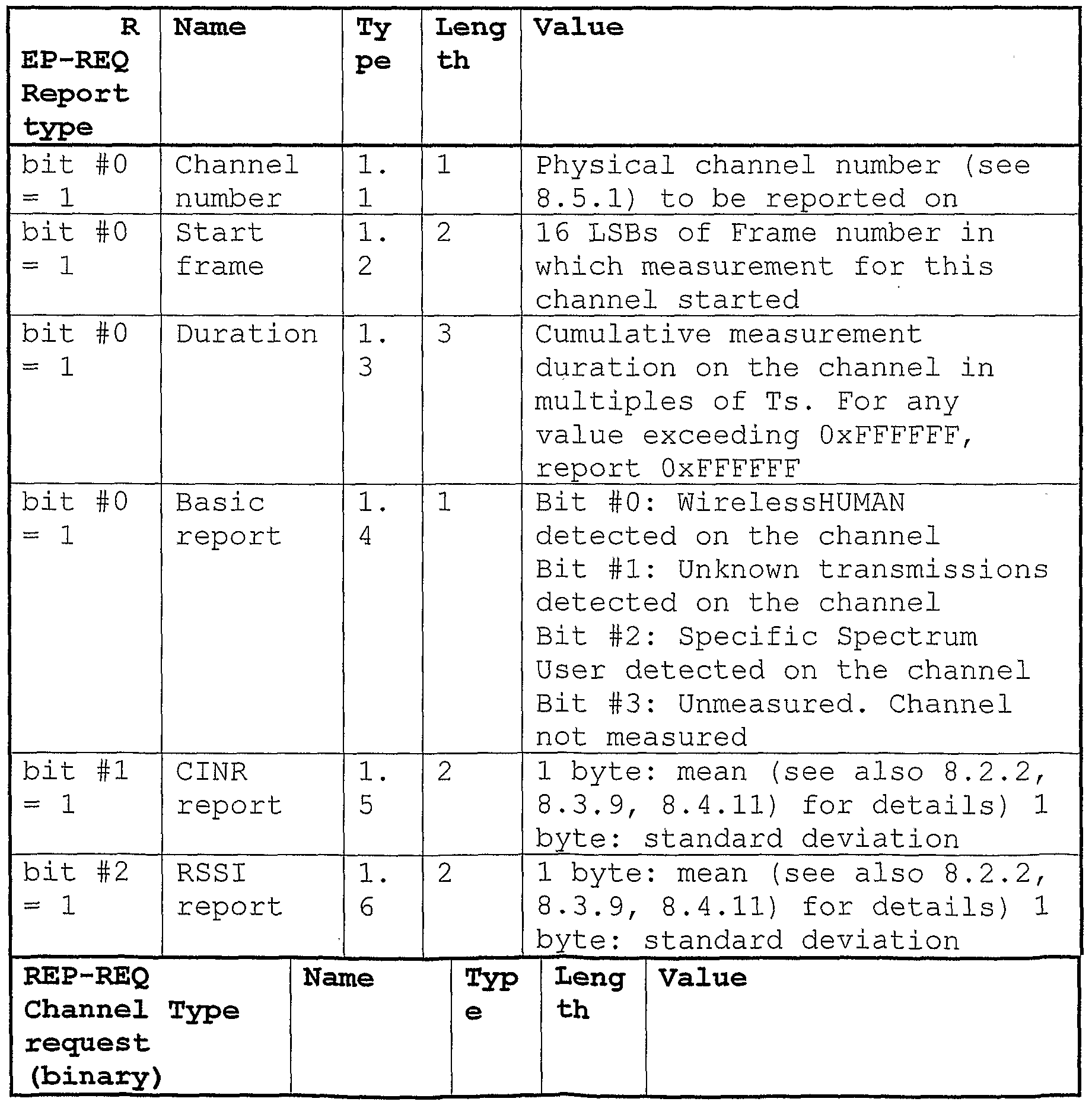
A report of channel types and information reported through the channel measurement report response message include parameters as shown in the following Table 6B . [Table 6B]
Figure imgf000022_0002
Figure imgf000023_0001
The RS described above in the conventional technologies can be fixedly installed between a base station (BS) and a terminal. The conventional RS also can be installed on a moving vehicle to increase the service coverage of the BS or to reduce shadow areas.
However, there is no conventional technology which suggests a method for deciding when to perform direct communication between the BS and the terminal and when to perform relay communication through the RS.
The conventional communication system provides a method in which the BS receives, directly from a mobile terminal, signal quality information of downlink/uplink channels between the BS and the mobile terminal. According to this signal quality information of downlink/uplink channels, MS performs handover.
However, no conventional communication technologies provide a method for the communication system including the
RS in which the terminal, the RS, and the BS can communicate with each other according to changes of status of radio channel. Disclosure of Invention
An object of the present invention devised to solve the problems lies on providing a method in which a BS decides whether to perform direct communication or relay communication with a terminal and controls the communication in a broadband wireless access system.
It is another object of the present invention to provide a method for controlling data communication between the RS, the terminal, and the BS according to changes in communication environments in the communication system including the RS .
The object of the present invention can be achieved by providing a relay communication control method applied to a broadband wireless access system including a relay station, the method comprising obtaining information regarding a channel status between a base station and a terminal; obtaining information regarding a channel status between the relay station and the terminal if it is determined, by checking the information regarding the channel status between the base station and the terminal, that a specified condition is satisfied; comparing the channel status between the base station and the terminal with the channel status between the relay station and the terminal; and performing direct communication or relay communication between the base station and the terminal, according to the comparison.
In another aspect of the present invention, provided herein is a relay communication control method applied to a broadband wireless access system including a relay station, the method comprising periodically obtaining information regarding a channel status between a base station and a terminal and information regarding a channel status between the relay station and the terminal; comparing the channel status between the base station and the terminal with the channel status between the relay station and the terminal; and performing direct communication or relay communication between the base station and the terminal, according to the comparison. The present invention relates to a terminal that communicates with a BS through an RS. The present invention provides a method for the RS reporting to the BS when information regarding uplink/downlink signal quality between the RS and the terminal is reduced. In the description of the present invention, the term "signal quality information" refers to information (or value) regarding the signal quality such as CINR or RSSI information (or value) . The present invention also provides a mechanism ensuring that, when a terminal in the coverage of the BS receives a service from the BS through the RS, the RS reports a channel status between the RS and the terminal to the BS. The present invention also provides a method for relaying a service, which has been relayed through a first specific RS, through a second specific RS.
In another aspect of the present invention, provided herein is a method for reporting a channel status in a communication system including at least one relay station including a first relay station communicating with a base station and at least one terminal, the method comprising the first relay station measuring a channel quality with a first terminal; and comparing the measured channel quality with a threshold and transmitting a report message to the base station according to the comparison, wherein the report message is a message requesting the base station to measure a channel quality of at least one of a second relay station and the first terminal in communication with the base station.
In a further aspect of the present invention, provided herein is a method for reporting a channel status in a communication system including a base station communicating with at least one of one or more terminals and one or more relay stations, the method comprising the base station receiving a report message requesting channel quality measurement from a first relay station that performs relaying for a first terminal/ and measuring a channel quality of at least one of the first terminal and a second relay station according to the report message.
In another aspect of the present invention, provided herein is a method for reporting a channel status in a communication system including one or more relay stations and at least one base station, the method comprising a terminal in communication with the communication system transmitting data to a first relay station; and receiving data transmitted through a data path selected according to a channel quality measured by the transmitted data, wherein the data path is determined based on comparison of the measured channel quality with a channel quality between the terminal and one of the base station and a second relay station.
Brief Description of Drawings
The accompanying drawings, which are included to provide a further understanding of the invention, illustrate embodiments of the invention and together with the description serve to explain the principle of the invention.
In the drawings :
FIG. 1 illustrates a network including an RS.
FIG. 2 illustrates an example of a conventional frame structure for the RS. FIG. 3 illustrates an example of a conventional OFDMA physical layer frame structure.
FIG. 4 is a flow chart of a method for deciding whether to perform direct communication or relay communication;
FIG. 5 is a flow chart of a method for deciding whether to perform direct communication or relay communication;
FIG. 6 is a flow chart of a method for deciding whether to perform direct communication or relay communication;
FIG. 7 is a flow chart of a method for deciding whether to perform direct communication or relay communication; FIG. 8 is a flow chart of a method for deciding whether to perform direct communication or relay communication;
FIG. 9 is a flow chart of a method for deciding whether to perform direct communication or relay communication;
FIG. 10 illustrates an example of a communication system for implementing an embodiment of the present invention.
FIG. 11 is a process flow diagram according to the embodiment of the present invention. Best Mode for Carrying Out the Invention
The above and other objects, features, and advantages of the invention will be more clearly understood from the following detailed description of the preferred embodiments of the present invention.
A method for controlling communication through an RS according to a first embodiment of the present invention will now be described. FIRST EMBODIMENT A base station (BS) compares an uplink signal quality between the BS and a terminal with an uplink signal quality of signals received by the BS through a relay station (RS) and decides whether to perform direct communication with the terminal or to allow the RS to relay signals communicated between the BS and the terminal. If the BS determines that it is necessary to increase the throughput, the BS attempts to relay signals for the terminal through the RS.
In order to obtain uplink signal quality information of the terminal, the BS causes the terminal to transmit signal quality information periodically or when a specific condition is satisfied.
The terminal can use a specific channel or a MAC message to transmit signal quality information periodically or when a specific condition is satisfied. For example, the specific channel includes a CQICH and the MAC message includes a REP-REQ/RSP MAC management message.
The following is a description of a procedure in which, while a BS and a terminal communicate directly with each other, an RS starts to relay signals communicated between the BS and the terminal.
If, while receiving a service from a BS, a terminal moves to the coverage of an RS or moves away from the BS so that an uplink signal quality of the terminal received by the BS is lowered or if the BS attempts to increase the throughput of communication with the terminal through the RS, the BS checks uplink signal quality information between the terminal and the BS. In particular, the BS compares the uplink signal quality information with uplink signal quality information obtained when an RS is present between the BS and the terminal. If the signal quality or the throughput with the RS is higher than the uplink signal quality without involving the RS, the BS provides a service to the terminal through the RS. Examples of a method in which the BS obtains signal quality information which is received by the RS are described as follows. The Method relates to a CQICH and a REP-REQ/RSP MAC management message.
The terminal which is present in the coverage of the BS can receive services from the BS through the RS. Uplink signal quality information between the terminal and the RS can be transmitted to the BS periodically or when a specific condition is satisfied.
First, a method for transmitting signal quality information through a CQICH when a specific condition is satisfied is described below.
A BS can allocates a CQICH for a terminal to an uplink and request downlink signal quality information from the terminal. If a measured value of the downlink signal quality information transmitted from the terminal to the BS or an uplink signal quality which is measured by the BS is less than a reference value, the BS requests the terminal to transmit downlink signal quality information via the CQICH channel. The BS can measure the uplink signal quality using the measured value of the downlink signal quality information transmitted from the terminal.
In addition, the BS sets the RS to monitor an uplink from the terminal and the RS, which has obtained uplink signal quality information of the terminal, requests the BS to allocate a CQICH zone. Specifically, if the terminal transmits downlink signal quality information through a CQICH zone, the RS receives the information from the terminal and checks uplink signal quality information between the terminal and the RS. Then, the RS transmits the uplink signal quality information between the terminal and the RS through the CQICH zone corresponding to the terminal which the BS has allocated. If the uplink signal quality information transmitted for the RS and the uplink signal quality information obtained by the RS are higher than signal quality information received directly from the terminal and higher than a reference value, the BS provides a service to the terminal through the RS.
FIG. 4 is a flow chart of an embodiment of a method for deciding whether to perform direct communication or relay communication.
As shown in FIG. 4, a base station (BS) allocates a CQICH to a first terminal or mobile station (MS) , a second terminal, and a third terminal and requests downlink signal quality information from the terminals (S401-S403) . The BS receives signal quality information from the terminals (S404-S406) and determines, using the received information, whether or not the received quality of each of the terminals is less than a reference value.
If the received quality of any of the second and third terminals is less than the reference value, the base station requests an RS to monitor an uplink of the corresponding terminal (S408-S409) . Each of the second and third terminals transmits signal quality information through a corresponding CQICH (S410-S413).. Then, if the RS obtains the signal quality information transmitted from the second and third terminals and radio resources are allocated by the BS to transmit signal quality information (S414), the RS transmits uplink signal quality information of each of the second and third terminals through a CQICH zone (S415-S416) . If uplink signal quality information received through the RS and uplink signal quality information obtained by RS are higher than uplink signal quality information received directly from each of the first and second terminals, the BS performs relay communication with the second and third terminals through the RS (S417-S419) .
The following is a description of a method for transmitting signal quality information using a MAC management message when a specific condition is satisfied. If downlink signal quality information transmitted from a terminal to a BS or uplink signal quality information, measured by the downlink signal quality information which is received by the BS, is less than a reference value, the BS allocates radio uplink resources to the terminal. The BS also transmits a message requesting the RS to monitor the uplink signal quality of the terminal. If each terminal to which the BS has allocated radio uplink resources has data to transmit to the BS, the terminal transmits the data. If the terminal has no data to be transmitted to the BS, the terminal performs periodic ranging .
If the terminal transmits data, the RS transmits uplink signal quality information of the data received from the terminal using radio resources which the BS has allocated to the RS. When the terminal performs periodic ranging, the terminal transmits a ranging request message to the BS through the RS. Through the ranging request message, the RS can obtain uplink signal quality information from the terminal. The RS can transmit the uplink signal quality information of the terminal, which the RS has obtained, through a MAC message to the BS. The BS compares the uplink signal quality information transmitted by the RS with uplink signal quality information received directly from the terminal and decides whether to perform direct communication or relay communication with the terminal.
FIG. 5 is a flow chart of an embodiment of a method for deciding whether to perform direct communication or relay communication. As shown in FIG. 5, if a BS requests downlink signal quality information from each of first and second terminals through a REP-REQ message (S501, S503), then each of the terminals transmits downlink signal quality information to the BS through a REP-RSP message (S502, S504) . The BS checks the received downlink signal quality of each of the terminals and/or an uplink signal quality measured by the REP-RSP. If the downlink signal quality and/or the uplink signal quality is less than a reference value, the BS allocates radio uplink resources of the corresponding terminal (the first terminal in the example of FIG. 5) (S505) . The BS then requests each RS to monitor an uplink between the corresponding terminal and the RS (S506, S507) .
The terminal (the first terminal in the example of FIG. 5), to which the BS has allocated an uplink radio resources, checks whether or not it has data to be transmitted to the BS. If the terminal has data to be transmitted, the terminal transmits the data through the allocated radio uplink resources (S508). If the terminal transmits data to the base station, the RS (the first RS in the example of FIG. 5) transmits uplink signal quality information of the data received from the terminal to the BS by incorporating the uplink signal quality information into a MAC message. If it has no data to be transmitted to the BS, the terminal performs periodic ranging. Specifically, the terminal transmits a ranging request message to the BS and the RS (S511, S512) . The RS can receive the uplink signal quality through the ranging request message received from the terminal. The RS transmits signal quality information between the RS and the terminal to the BS through a MAC message signal quality report response message (REP-RSDetect-RSP) (S513) .
The BS compares uplink signal quality information, measured by the signal quality report response message
(REP-REDetect-RSP) , and/or the uplink signal quality information of the terminal, which the RS has obtained and transmitted to the BS, with uplink signal quality information received directly from the terminal. If the uplink signal quality information of the terminal received through the RS is higher than the uplink signal quality information received directly from the terminal and higher than a reference value, the BS provides services to the terminal through the RS (the first RS in the example of FIG. 5) (S514, S515) .
The BS can cause the RS to periodically report uplink signal quality information between the terminal and the RS to the BS. The BS also decides, using the reported information, whether to perform direct communication or relay communication.
First, a method for receiving signal quality information through a CQICH is described below.
The BS allocates a CQICH for a terminal to the uplink and periodically checks downlink signal quality information which the terminal has transmitted to the BS, or uplink signal quality information of this downlink information. Specifically, the BS requests the terminal to transmit downlink signal quality information via the CQICH and sets the RS to monitor an uplink from the terminal during a corresponding period. Upon receiving the uplink signal quality information of the terminal, the RS requests the BS to allocate a CQICH zone. If each terminal transmits downlink signal quality information through a CQICH zone, the RS receives the information and checks uplink signal quality information and then transmits the signal quality information between the terminal and the RS through a CQICH zone of the corresponding terminal.
The BS compares the two signal quality information values between the terminal and the RS with the directly received signal quality information. If the uplink signal quality information received through the RS is higher than the directly received signal quality information and higher than a reference value, the BS provides services to the terminal through the RS. This procedure is repeated during the corresponding period. If the period is completed or if the CQICH is de-allocated, then the procedures are canceled. FIG. 6 is a flow chart of an embodiment of a method for deciding whether to perform direct communication or relay communication.
As shown in FIG. 6, a BS allocates respective areas for a first RS, a first terminal, a second terminal, and a third terminal in a Fast-Feedback channel zone. The BS then requests downlink signal quality information of the first RS, the first terminal, the second terminal, and the third terminal (S601-S604). The BS requests the first RS to monitor uplink signal quality information received from the first terminal, the second terminal, and the third terminal (S605) . Each of the first terminal, the second terminal, and the third terminal transmits the signal quality information through the corresponding CQICH (S606- S612) . In order to obtain uplink signal quality information of each terminal, which the first RS has obtained, the BS allocates a CQICH of the first RS (S613) . The first RS transmits the respective uplink quality information of the first terminal, the second terminal, and the third terminal, which the first RS has obtained, through the allocated CQICH areas of the first RS (S614-S616) .
If the uplink signal quality information received through the first RS and/or the uplink signal quality information of a terminal, which the first RS has obtained, is higher than uplink signal quality information received directly from the terminal and is also higher than a reference value, the BS performs relay communication with the terminal through the RS (S617-S619) .
A method for periodically receiving signal quality information using a MAC message will now be described. To obtain the uplink signal quality information of a terminal, a BS periodically allocates uplink radio resources to the terminal and transmits a MAC message to an RS to request to monitor the uplink of the terminal. If each terminal, to which the BS has assigned an uplink, has data to be transmitted to the BS, the terminal transmits the data and, if the terminal has no data to be transmitted to the BS, the terminal performs periodic ranging.
If the terminal transmits data to the BS, the RS transmits uplink signal quality information of the data obtained from the terminal via allocated radio resources. When the terminal performs periodic ranging, the terminal transmits a ranging request message to the BS through the RS. Through the ranging request message, the RS can receive uplink signal quality information from the terminal. The RS transmits the uplink signal quality information of the terminal, which the RS has received, via a MAC message to the BS. Upon receiving data from the RS, the BS compares uplink signal quality information of the reception of this data and/or uplink signal quality information between the RS and the terminal transmitted from the RS with uplink signal quality information received directly from the terminal. If the uplink signal quality information of the terminal received through the RS is higher than the uplink signal quality information received directly from the terminal, the BS provides services to the terminal through the RS.
FIG. 7 is a flow chart of an embodiment of a method for deciding whether to perform direct communication or relay communication. A BS allocates respective radio uplink resources to first and second terminals (S701, S702). The BS transmits a signal quality detection report request message (REP-RSDetect-REQ) to first and second RSs to allow the first and second RSs to monitor respective uplinks from the first and second terminals (S703, S704) .
If the first terminal, to which the BS has allocated radio uplink resources, has data to be transmitted to the BS, the first terminal transmits the data using the allocated radio uplink resources (S705, S706) . If the first terminal transmits the data to the BS, the RS checks an uplink signal quality of the data obtained from the terminal and transmits the signal quality information to the BS through a signal quality detection report response message (REP-RSDetect-RSP) (S707) . If the second terminal has no data to be transmitted to the BS, the second terminal performs periodic ranging. Specifically, the second terminal transmits a ranging request message (RNG-REQ) (S708, S709) . The second RS can confirm uplink signal quality information from the ranging request message (RNG-REQ) obtained from the second terminal. The second RS transmits the received uplink signal quality information of the terminal via a signal quality detection report response message (REP-RSDetect-RSP) to the BS (S710) . Using the received information, the BS determines whether or not the signal quality when the BS performs direct communication with the terminal is higher than the signal quality when the BS performs relay communication with the terminal using the RS. If it is determined that the signal quality of the direct communication is higher than the signal quality of the relay communication, the BS performs direct communication with the terminal. On the other hand, if it is determined that the signal quality of the direct communication is lower than the signal quality of the relay communication, the BS performs relay communication with the terminal using the RS.
The BS provides a service to the terminal through the RS (S711, S712) . If uplink signal quality information of the terminal received through the RS is higher than uplink signal quality information received directly from the terminal, the BS performs communication with the terminal without involving the RS (S713) .
If a period for receiving the uplink signal quality information the is nonzero and the BS provides a service to the terminal through the RS, the BS allocates an uplink resources to the terminal through the RS and, if the terminal has data to be transmitted to the BS, the terminal transmits the data via the allocated resources (S714-S717) .
If the first terminal transmits data to the BS, the first
RS checks uplink signal quality information of the data received from the terminal and transmits the uplink signal quality information to the BS via a REP-RSDetect-RSP message which is response to the REP-RSDetect-REQ message
(S718) .
If the first terminal has no data to be transmitted to the BS, the first terminal performs periodic ranging. When the first terminal performs periodic ranging, the first terminal transmits a RNG-REQ message to the BS through the first RS (S719, S720) . The first RS can receive uplink signal quality information of the first terminal from the RNG-REQ message. The first RS transmits the uplink signal quality information of the terminal, which the first RS has obtained, via a REP-RSDetect-RSP message to the BS. If the BS requests the downlink signal quality information of the terminal directly from the terminal without involving the RS, the BS returns to the process of step S701.
A description will now be given of a method in which a BS and a terminal switch to perform direct communication with each other while performing relay communication with each other using an RS. In the case that a terminal in the coverage of an RS transmits uplink signal quality information between a BS and the terminal directly to the BS without involving the RS, the BS provides a service directly to the terminal without involving the RS if the uplink signal quality information received by the BS directly from the terminal is similar to or higher than uplink signal quality information of the terminal received by the RS.
If, while receiving a service from the BS through the RS, the terminal leaves the coverage of the RS or approaches the BS so that uplink signal quality information, of the terminal received by the BS is improved or if the BS desires to transmit data directly to the terminal without involving the RS, the BS compares the uplink signal quality information received from the terminal with uplink signal quality information obtained when an RS is present between the terminal and the BS. If the uplink signal quality information between the BS and the terminal received directly from the terminal is similar to or higher than the uplink signal quality information between the BS and the terminal received through the RS, the BS provides the service directly to the terminal without involving the RS.
The following is a description of a procedure in which, while a BS and a terminal communicate directly with each other, an RS is allowed to relay signals communicated between the BS and the terminal.
If downlink signal quality information of the terminal received by the BS through the RS or uplink signal quality information measured by the downlink signal quality information is less than a reference value or if downlink/uplink signal quality information received by the BS from the terminal is higher than the reference value and is also similar to or higher than downlink/uplink signal quality information of the terminal received through the RS, the BS requests uplink signal quality information of the terminal .
In order to obtain downlink signal quality information of the terminal, the BS allocates a CQICH zone to the terminal. The BS can allocate the CQICH zone directly to the terminal and can also allocate the CQICH zone through the RS. If downlink signal quality information of each terminal included in a CQICH zone of the terminal or uplink signal quality information of the reception of the downlink signal quality information is higher than the reference value and is also higher than uplink signal quality information of the terminal received through an RS, the BS provides a service directly to the terminal without involving the RS.
FIG. 8 is a flow chart of an embodiment of a method for deciding whether to perform direct communication or relay communication.
In the case where a BS allocates a CQICH zone for receiving downlink signal quality information of a terminal, the BS requests downlink signal quality information of the terminal (a first terminal in the example of FIG. 8) (S801) . The BS checks downlink signal quality information of the terminal received by the BS or uplink signal quality information measured by the downlink signal quality information (S802). If the signal quality information is equal to or higher than a reference value, the BS requests that an RS (a first RS in the example of FIG. 8) monitor an uplink of the terminal (i.e., the first terminal) which provides the signal quality information equal to or higher than the reference value (S803) and then requests that the terminal transmit its downlink signal quality information through a CQICH allocated to the terminal (S804) .
The first terminal transmits downlink signal quality information between the first terminal and the BS to the BS via the allocated CQICH (S805) . The first RS receives uplink signal quality information between the first RS and the first terminal (S806) . The BS allocates a CQICH zone for the first RS to allow the first RS to transmit the received uplink signal quality information of the first terminal (S807) . The first RS transmits the received uplink signal quality information of the first terminal through the allocated CQICH zone of the first RS (S808) . If uplink signal quality information received directly from the first terminal without involving the first RS is higher than the uplink signal quality information of the first terminal received through the first RS, the BS provides a service directly to the first terminal without involving the first RS (S809) .
In order to obtain quality information of uplink signals received from the terminal, the BS allocates an uplink zone of the terminal through the RS or allocates an uplink zone directly to the terminal without involving the RS.
In the former case where the BS allocates an uplink zone of the terminal through the RS, if the terminal has data to be transmitted to the BS, the terminal transmits the data to the RS via the allocated zone and the RS then transmits the data to the BS. If the terminal has no data to be transmitted to the BS, the terminal performs periodic ranging and requests a ranging procedure through the BS. Here, the BS can obtain quality information of uplink signals of the terminal received through the RS. If the uplink signal quality information received through the RS is less than the reference value, the BS allocates an uplink resources directly to the terminal to transmit data directly to the terminal or obtains quality information of uplink signals of the terminal received from the RS through periodic ranging. If the uplink signal quality information received directly from the terminal is equal to or higher than the reference value and is also higher than the uplink signal quality information of the terminal received through the RS, the BS provides a service directly to the terminal without involving the RS.
In the latter case where the BS allocates an uplink zone directly to the terminal without involving the RS, if uplink signal quality information of the terminal obtained directly from the terminal is equal to or higher than the reference value and is also higher than uplink signal quality information of the terminal received through the RS, the BS provides a service directly to the terminal without involving the RS.
FIG. 9 is a flow chart of an embodiment of a method for deciding whether to perform direct communication or relay communication. As shown in FIG. 9, when a BS performs communication with a first terminal through a first RS, the BS allocates an uplink area of the first terminal to an uplink zone of the first RS (S901) and allocates the uplink allocation area of the first terminal through the first RS (S902) . The BS transmits a REP- RSDetect-REQ message to the first RS to allow the first RS to monitor an uplink from the first terminal (S903) . If the first terminal has data to be transmitted to the BS, the first terminal transmits the data to the first RS and the first RS then transmits the data to the BS (S904, S905) . Here, the first RS can obtain uplink signal quality information from the first terminal. The first RS transmits the received uplink signal quality information to the BS via a REP-RSDetect-RSP message (S906) . If the first terminal has no data to be transmitted to the BS, the first terminal performs periodic ranging. To perform the periodic ranging, the first terminal transmits a RNG-REQ message to the first RS and the first RS then transmits it to the BS (S907, S908) . Here, the first RS can obtain uplink signal quality information from the first terminal. The first RS transmits the received uplink signal quality information of the first terminal to the BS via a REP- RSDetect-RSP message (S909) . If the uplink signal quality information of the first terminal received through the first RS (RS#1) is less than a reference value, the BS allocates uplink resources to the first terminal (S910) . If the first terminal, to which the BS has allocated uplink resources, has data to be transmitted to the BS, the first terminal transmits the data via the uplink area allocated to the first terminal (S912) . Here, the BS can receive uplink signal quality information from the first terminal. If the first terminal has no data to be transmitted to the BS, the first terminal transmits a RNG-REQ message to the BS. Here, the first terminal can obtain uplink signal quality information from the first terminal (S915) . If the uplink signal quality information between the BS and the first terminal is equal to or higher than the reference value and is also higher than uplink signal quality information of the first terminal received through the first RS, the BS provides a service directly to the first terminal without involving the first RS (S918) . In the case that the BS communicates directly with the first terminal without involving the first RS, the BS allocates an uplink of the first terminal (S910) and the BS transmits a REP-RSDetect-REQ message to the first RS to request the first RS to monitor uplink signal quality information received from the first terminal (S911) .
If the first terminal, to which the BS has allocated uplink resources, has data to be transmitted to the BS, the first terminal transmits the data via the resources allocated to the first terminal. Here, the BS can receive uplink signal quality information of the first terminal
(S912) . The first RS can obtain uplink signal quality information from the first terminal (S913) . The first RS transmits the uplink signal quality information of the first terminal to the BS via a REP-RSDetect-RSP message (S914). If the first terminal has no data to be transmitted to the BS, the first terminal transmits a RNG-REQ message to the BS. Here, the BS can receive uplink signal quality information of the first terminal (S915) . The first RS can obtain uplink signal quality information from the first terminal. The first RS transmits the received uplink signal quality information of the first terminal to the BS via a REQ-RSDetect-RSP message (S914) . If the uplink signal quality information between the BS and the first terminal is equal to or higher than the reference value and is also higher than uplink signal quality information of the first terminal received through the first RS, the BS provides a service to the first terminal without involving the first RS (S918) . The BS periodically receives uplink signal quality information from a terminal and an RS and, using this information, the BS can decide whether to perform direct communication or relay communication through the RS. Specifically, the BS periodically requests uplink signal quality information between the terminal and the RS. In order to obtain the quality information of downlink/uplink signals received from the terminal, the BS obtains uplink signal quality information of the terminal through the RS or receives uplink signal quality information directly from the terminal without involving the RS. The present invention suggests a method in which a BS checks uplink signal quality information between the BS, a terminal, and an RS periodically or when a specific event has occurred. In this method, if an RS is present between the BS and the terminal, the BS decides whether or not to perform relay communication through the RS by comparing uplink signal quality information between the BS and the terminal with uplink signal quality information between the BS, the RS, and the terminal. Accordingly, the BS can provide a seamless service and the coverage of the BS can be increased and the service can also be provided normally even in shadow areas. In addition, the BS can perform group-based management of terminals that receive services from the BS through RSs, thereby allowing efficient resource distribution of the BS and also reducing power consumption of terminals.
Table 7 is a table of UIUC values.
[Table 7]
Figure imgf000051_0001
15 Extended UIUC
Table 8 illustrates an example where the type of UIUC is 15, i.e., when an extended UIUC is selected. "Extended UIUC = OB" indicates RS-Detect-MS_IE and "Extended UIUC = OC" indicates RS-CQICH_Alloc_IE .
Table 8 is a table illustrating an example of a REP- RSDetect-RSP message.
[Table 8]
Figure imgf000052_0001
Table 9 illustrates an example of an RS-Detect MS IE format .
[Table 9]
Figure imgf000052_0002
W 2
51
Figure imgf000053_0001
Table 10 illustrates an example of a RS- CQICH_Alloc_IE format. [Table 10]
Figure imgf000053_0002
Figure imgf000054_0001
Table 11 illustrates an example of a REP-RSDetect-REQ message.
[Table 11]
Figure imgf000054_0002
Table 12 illustrates an example of a REP-RSDetect-RSP essage.
[Table 12]
Figure imgf000055_0001
SECOND EMBODIMENT
A second embodiment of the present invention includes an example of a method for reporting a channel status in a system including an RS. The second embodiment will now be described with reference to the accompanying drawings.
An embodiment of the present invention relates to a terminal which communicates with a base station (BS) through a relay station (RS) . The BS is a node which is connected to the backbone network to communicate with the RS and the terminal. The RS is a node which communicates with the BS. Preferably, the RS communicates data wirelessly with the BS. More preferably, the RS communicates with the BS according to an OFDM/OFDMA scheme. The RS performs relaying between the BS and the terminal. The term "relaying" refers to a series of communication processes of receiving data destined for the terminal from the BS and transmitting it to the terminal and receiving data destined for the BS from the terminal and transmitting it to the BS. Preferably, the relaying is performed according to the OFDM/OFDMA scheme as described above. Preferably, the relaying is performed according to a variety of communication schemes such that data encoded according to a first scheme is received and decoded and the decoded data is encoded according to the first scheme or a second scheme and the encoded data is then transmitted to the BS. The relaying may include a process of amplifying and transmitting/receiving communication data signals of the terminal. The relaying may also include a process of attaching additional data to data received from the terminal and then transmitting it to the BS or a process of transforming and transmitting data received from the terminal to the BS. The RS is connected to the BS. There is no limit on the number of RSs. The terminal is a node that is connected to the BS or the RS and may be a mobile terminal that is movable or a stationary terminal that is fixed to a specific position.
In an embodiment of the present invention, the RS requests the BS to measure a channel quality when a specific event has occurred. Specifically, this embodiment provides a mechanism ensuring that, when a terminal in the coverage of the BS receives a communication service from the BS through the RS, the RS reports a channel status between the RS and the terminal to the BS. This embodiment also provides a method for relaying a service, which has been relayed through a first specific RS, through a second specific RS.
The RS requests the BS to measure the channel quality as described above. The channel quality request is made by an RS (hereinafter referred to as a first RS) which currently performs relaying for the terminal. The channel quality may be a channel quality between the BS and an RS (hereinafter referred to as a second RS) other than the first RS or a channel quality between the BS and the terminal. The channel quality indicates a channel status between specific nodes and, for example, the quality of signals transmitted through an uplink or the quality of signals transmitted through a downlink. The channel quality can be measured according to a variety of methods. For example, a specific channel to be subjected to channel quality measurement is set and the set channel is then monitored to measure its quality. In another method, the quality of a downlink may be measured by transmitting a message requesting to measure the quality of the downlink to the terminal and then demodulating a message received from the terminal to measure the quality of the downlink. In this case, the quality of the uplink may be measured using a message reporting the downlink quality. According to this embodiment, the first RS requests the BS to measure the channel quality when a specific event has occurred as described above. To make this request, the first RS may transmit information regarding a specific terminal that is in a poor connection state and may transmit a channel status between the first RS and the specific terminal and may also transmit a message requesting the BS to measure the channel quality. After receiving the channel quality measurement request message, the BS may measure a channel quality between the first RS and the BS or may measure a channel quality between the terminal and the BS. For example, when an event occurs as a quality level regarding an uplink signal quality between the first RS and a terminal is reduced below a reference value, the first RS reports the terminal, whose uplink signal quality information has been reduced below the reference value, to the BS. The term "signal quality information" refers to information (or value) regarding the signal quality such as CINR or RSSI information (or value) . After receiving the report from the first RS, the BS may request uplink signal quality information between the terminal and an RS (for example, the second RS) adjacent to the first RS or may request information regarding the quality of direct uplink/downlink signals between the BS and the terminal. According to this embodiment, the first RS may provide information regarding a second RS which relays signals of the terminal to the BS when a specific event has occurred. Specifically, when an event such as a reduction in the channel quality between the first RS and the terminal has occurred, the first RS can propose a candidate RS that can relay the terminal. Through this operation, the first RS can assist the BS in measuring the channel quality. To propose the candidate RS, it is necessary for the first RS to have information regarding RSs located around the first RS. Accordingly, it is preferable that the BS provide information regarding neighbor RSs located around the first RS to the first RS. Preferably, the information regarding RSs located around the first RS is broadcasted. More preferably, the RS information is repeatedly broadcasted at regular or irregular intervals. More preferably, the neighbor RS information is information regarding at least one RS. Upon the proposal of the candidate RS, the BS may preferentially measure the channel quality of the candidate RS. According to this embodiment, the first RS may request the BS to preferentially measure the channel quality with the terminal. If the first RS requests the BS to measure a channel quality between the terminal and the BS, the BS measures the channel quality between the terminal and the BS. On the other hand, if the first RS requests the BS to measure a channel quality between the terminal and the second RS, the BS measures the channel quality between the terminal and the second RS.
According to the present invention, the BS preferably measures the channel quality according to the request of the first RS and decides, based on the channel quality measurement results, whether to allow the second RS to perform relaying for the terminal, to allow the first RS to continue relaying for the terminal, or to communicate directly with the terminal. For example, the BS can select one of the first and second RSs, which provides uplink signal quality information that is equal to or higher than the reference value and that is also higher than that of the other RS, by comparing the uplink signal quality information between the second RS and the terminal with the uplink signal quality information between the first RS and the terminal. In addition, if the channel quality between the terminal and the BS is measured to be equal to or higher than a specific threshold or to be higher than the channel quality between the RS and the terminal, the BS may communicate directly with the terminal without involving the RS. In a method of deciding whether or not to communicate directly with the terminal, the BS may use the conventional CQICH channel and REP-REQ/RSP MAC management message for the decision. The RS may obtain the channel quality information between the RS and the terminal when the BS requests the RS to obtain. The RS may also previously obtain the channel quality information before the BS makes the request and then immediately report it to the BS upon the request of the BS.
The procedure of this embodiment is activated when a specific event has occurred as described above. The event may occur when the channel quality between the first RS and the terminal is reduced below a specific threshold. The event may be repeated at predetermined time intervals and may also be repeated at irregular time intervals. The event may occur by a control message or the like from a backbone network which controls the BS.
Examples in which the first RS requests the channel quality of the terminal from the BS when the terminal is present in the coverage of the BS will now be described.
(1) Example in which BS switches to communicate directly with terminal (MS) while communicating with terminal through RS: If the terminal leaves the coverage of the first RS to move to another area in the coverage of the BS while receiving a service from the BS through the first RS, a quality level regarding the uplink signal quality between the first RS and the terminal is reduced. The first RS then requests the BS to obtain information regarding a direct uplink signal quality between the BS and the terminal. After receiving the uplink signal quality information from the terminal, the BS communicates directly with the terminal without involving the RS if the direct communication with the terminal is better.
(2) Example in which, while performing relaying for terminal through one RS, BS performs handover to adjacent RS:
If the terminal enters the coverage of the second RS adjacent to the first RS while receiving a service from the BS through the first RS, a quality level regarding the uplink signal quality between the first RS and the terminal is reduced. The first RS then requests the BS to obtain information regarding an uplink signal quality between the second RS and the terminal. After receiving the uplink signal quality information between the second RS and the terminal, the BS selects and allows one of the first and second RSs, which provides a higher quality, to perform relaying. This embodiment suggests a process in which the first RS reports information of the terminal to the BS when a quality level regarding the uplink signal quality between the first RS and the terminal is reduced below a reference value, so that the BS can select an appropriate RS in the coverage of the BS and decide whether or not to communicate directly with the terminal and it is also possible to increase the throughput and to ensure a seamless service.
FIG. 10 is an example of a communication system for implementing an embodiment of the present invention. FIG. 11 is a process flow diagram according to the embodiment of the present invention. How the communication system operates according to this embodiment of the present invention will now be described with reference to FIGs. 10 and 11. The example of FIG. 11 suggests a method for the first RS reporting to the BS using an RS-REPORT MAC management message according to this embodiment.
The communication system of FIG. 10 includes one BS and two RSs (first and second RSs) and also includes at least one terminal (first terminal) which communicates with the first or second RS or the BS. When the first terminal communicates with the BS through the first RS, a channel status between the first terminal and the first RS may be worsened below a reference value as the first terminal moves to the coverage of the second RS while receiving a service from the BS through the first RS. In this case, the first RS reports to the BS. This reporting may include transmitting a REP-REQ MAC message from the first RS to the BS. When receiving the REP-REQ MAC message, the BS may obtain a channel status between the first terminal and the BS and a channel status between the second RS and the terminal .
The process flow diagram of FIG. 11 will now be described. The example of FIG. 11 can be applied when the first terminal leaves the coverage of the first RS and enters the coverage of the second RS.
The BS which communicates with the terminal will now be referred to as a serving BS. The serving BS communicates with the terminal using the first RS (SIlOl- S1104) . That is, the first RS can relay data for the first terminal. Specifically, the serving BS transmits data to the first RS (SIlOl) and the first RS then transmits the data to the first terminal (S1102) . Consequently, the first terminal receives a service from the serving BS. The first terminal transmits data to the first RS (S1103) and the first RS then transmits the data to the serving BS (S1104) .
If the first RS relays data in the above manner, the first RS can measure a channel quality between the first terminal and the first RS. The channel quality can be repeatedly measured at irregular time intervals and can also be measured by a control signal from an external node such as a BS or a backbone network. When the channel quality is measured, the RS checks whether or not the measured channel quality has been reduced below a specific reference value (S1105) . An uplink channel quality is checked as an example of the channel quality in the embodiment of FIG. 11.
When the channel quality is less than the reference value, the first RS transmits a report message to the serving BS (S1106) . The embodiment of FIG. 11 uses an RS- REPORT MAC management message as the report message. The report message includes a variety of information. In the embodiment of FIG. 11, the report message includes information regarding the channel quality between the first RS and the first terminal.
If a channel quality regarding the uplink signal quality of the first terminal received by the first RS (i.e., information regarding the uplink signal quality between the first terminal and the first RS) is less than the reference value, the first RS may obtain information regarding the uplink signal quality between the first terminal and another RS (for example, the second RS) adjacent to the first terminal in the serving BS. The serving BS may also obtain information regarding the channel quality between the first terminal and the serving BS .
The serving BS assigns uplink resources to the first terminal if the uplink signal quality reported from the first RS is less than the reference value (S1107) . The serving BS transmits a REP-RSDetect-REQ message, which contains a request of the first RS requesting that the uplink of the first terminal be monitored, to the second RS (S1108) .
If the first terminal has data to be transmitted to the serving BS after the serving BS assigns the uplink resources to the first terminal at step S1107, the first terminal transmits the data to the serving BS through the assigned uplink resources (S1109) . When the first terminal transmits data to the serving BS, the second RS checks uplink signal quality information of the data received from the first terminal (SlIlO) . The second RS transmits the uplink signal quality information via a REP-RSDetect-RSP message, which is a response to the uplink monitoring request message (REP-RSDetect-REQ) , and transmits the REP- RSDetect-RSP message to the serving BS (Sllll) .
If the first terminal has no data to be transmitted to the serving BS after the serving BS assigns the uplink to the first terminal at step S1107, the first terminal performs periodic ranging. When the first terminal performs periodic ranging, the first terminal transmits an RNG-REQ message to the serving BS (S1112) . When the second RS receives the RNG-REQ message from the first terminal, the second RS can check the uplink signal quality information of the first terminal (S1113) . The second RS transmits the received signal quality information of the first terminal through a REP-RSDetect-RSP message to the serving BS (S1114) .
The serving BS may request the channel state information directly from the first terminal without involving the RS. In this case, the serving BS requests uplink signal quality information of the first terminal by transmitting a conventional REP-REQ message to the first terminal. When the first terminal receives a REP-RSP message from the serving BS (S1115), the first terminal transmits information regarding the uplink signal quality between the serving BS and the first terminal to the serving BS through a REP-RSP message (S1116) . At step S1116, the serving BS can also obtain information regarding the signal quality of downlink and uplink channels present in the cell area between the serving BS and the first terminal .
After receiving the REP-RSDetect-RSP message from at least one RS other than the first RS, the serving BS compares the uplink signal quality information of the first terminal transmitted from the first RS with uplink signal quality information included in the REP-RSDetect-RSP message (S1117). Based on the comparison, the serving BS selects a specific RS, which provides uplink signal quality information that is equal to or higher than the reference value and that is also higher than that of other RSs, or decides whether or not to communicate directly with the first terminal. For example, when the channel quality between the second RS and the first terminal is equal to or higher than the reference value and the channel quality is also the highest, the serving BS may allows the second RS to perform relaying. In this case, the second RS performs relaying (S1118 and S1119) .
Table 13 illustrates an example of the RS-REPORT MAC management message used in the embodiment of FIG. 11. [Table 13]
Figure imgf000068_0001
Figure imgf000069_0001
The first RS can transmit CINR or RSSI information to the serving BS by transmitting the message of Table 13 containing the CINR or RSSI information to the serving BS. The CINR or RSSI is only an example of a parameter indicating the channel quality and the message may contain other types of parameters. The RS-REPORT MAC management message of Table 13 is an example of a message reporting information regarding the first terminal and the channel quality between the first terminal and the first RS and the message of Table 13 may contain other information. The first RS can help the serving BS check the channel quality by transmitting information regarding the second RS to the serving BS as described above and the message of Table 13 may also contain information regarding RSs located around the first RS. In addition, the first RS may request the serving BS to preferentially check the channel quality for the first terminal as described above. The priority regarding the channel quality checking may be included in the message of Table 13. For example, the priority order may be set so that the serving BS first checks a channel quality for direct communication with the terminal and then checks a channel quality for relaying through the RS.
The present invention provides a method for reporting a channel status in a communication system including a relay station, which has a variety of advantages. For example, a base station (BS) decides whether to perform direct communication or relay communication with a terminal and controls the communication in a broadband wireless access system, thereby increasing the throughput. The present invention also suggests a method in which a relay station (RS) reports information regarding the uplink signal quality between a mobile terminal and the RS to a BS. When an RS is provided between the BS and a mobile terminal, this method allows the BS to efficiently decide whether or not to allow the RS to perform relaying for the terminal. Accordingly, the BS can provide a seamless service and the coverage of the BS can be increased and the service can also be provided normally even in shadow areas. In addition, the BS can perform group-based management of mobile terminals that receive services from the BS through RSs, thereby allowing efficient resource distribution of the BS and also reducing power consumption of mobile terminals.
It will be apparent to those skilled in the art that various modifications and variations can be made in the present invention without departing from the spirit or W 2
69
scope of the invention. Thus, it is intended that the present invention cover the modifications and variations of this invention provided they come within the scope of the appended claims and their equivalents.

Claims

What is Claimed is:
1. A method for relay communication in a broadband wireless access system having a relay station, the method comprising : acquiring information regarding a channel status between a base station and a terminal; if the information regarding the channel status between the base station and the terminal satisfies a specified condition, acquiring information regarding a channel status between the relay station and the terminal; comparing the channel status between the base station and the terminal with the channel status between the relay station and the terminal; and performing direct communication or relay communication between the base station and the terminal, according to the comparison.
2. The method of claim 1, wherein the information regarding the channel status between the base station and the terminal is acquired using a signal transmitted via a CQICH.
3. The method of claim 1, wherein the information regarding the channel status between the base station and the terminal is acquired through a MAC management message.
4. The method of claim 1, wherein the direct communication is performed when the channel status between the base station and the terminal is better than the channel status between the relay station and the terminal .
5. The method of claim 1, wherein the relay communication is performed when the channel status between the relay station and the terminal is better than the channel status between the base station and the terminal.
6. A method for relay communication in a broadband wireless access system having a relay station, the method comprising: periodically acquiring a channel status between a base station and a terminal and a channel status between the relay station and the terminal; comparing the channel status between the base station and the terminal with the channel status between the relay station and the terminal/ and performing direct communication or relay communication between the base station and the terminal, according to the comparison.
7. The method of claim 6, wherein the information regarding the channel status between the base station and the terminal is acquired using a signal transmitted via a CQICH.
8. The method of claim 6, wherein the information regarding the channel status between the base station and the terminal is acquired via a MAC management message.
9. The method of claim 6, wherein the direct communication is performed when the channel status between the base station and the terminal is better than the channel status between the relay station and the terminal.
10. The method of claim 6, wherein the relay communication is performed when the channel status between the relay station and the terminal is better than the channel status between the base station and the terminal .
11. A method for reporting a channel status in a communication system having at least one relay station including a first relay station communicating with a base station and at least one terminal, the method comprising: measuring a channel quality with a first terminal; and comparing the measured channel quality with a threshold and transmitting a report message to the base station according to the comparison, wherein the report message is a message requesting the base station to measure a channel quality of a second relay station communicating with the base station and the first terminal communicating with the base station.
12. The method of claim 11, wherein the report message includes information regarding the channel quality.
13. The method of claim 11, wherein the report message includes information regarding the first terminal.
14. The method of claim 11, further comprising: receiving information regarding at least one relay station located around the first relay station from the base station, wherein the report message includes information regarding the at least one relay station located around the first relay station.
15. The method of claim 11, wherein, if the base station transmits data through the first relay station according to the report message, the method further comprises: receiving data for the first terminal from the base station; and transmitting the received data to the first terminal.
16. A method for reporting a channel status in a communication system having a base station communicating with at least one terminal and at least one relay station, the method comprising: receiving, by the base station, a report message requesting the base station to measure a channel quality from a first relay station, wherein the first relay station performs relaying for a first terminal; and measuring a channel quality of the at least one the first terminal and a second relay station according to the report message.
17. A method for reporting a channel status in a communication system having at least one relay stations and at least one base station, the method comprising: transmitting, by a mobile station, data to a first relay station; and receiving, by the mobile station, data transmitted through a data path, wherein the data path is selected based on a first channel quality which is measured using the transmitted data, wherein the data path is selected based on comparison of the first channel quality with a second channel quality between the terminal and one of the base station and a second relay station.
PCT/KR2006/004740 2005-11-11 2006-11-13 Method of controlling relay communication WO2007055544A2 (en)

Priority Applications (6)

Application Number Priority Date Filing Date Title
JP2008539938A JP4890559B2 (en) 2005-11-11 2006-11-13 Relay communication control method
EP06812573.1A EP1955561B1 (en) 2005-11-11 2006-11-13 Method of controlling relay communication
CA 2626895 CA2626895C (en) 2005-11-11 2006-11-13 Method of controlling relay communication
US12/093,128 US8284709B2 (en) 2005-11-11 2006-11-13 Method of controlling relay communication
CN2006800419790A CN101385371B (en) 2005-11-11 2006-11-13 Method of controlling relay communication
US13/595,921 US9059890B2 (en) 2005-11-11 2012-08-27 Method of controlling relay communication

Applications Claiming Priority (4)

Application Number Priority Date Filing Date Title
KR1020050108250A KR101128800B1 (en) 2005-11-11 2005-11-11 Method of Controlling Relay Communication
KR10-2005-0108250 2005-11-11
KR1020060004357A KR101128801B1 (en) 2006-01-16 2006-01-16 Method of channel status report in communication system having at least one relay station
KR10-2006-0004357 2006-01-16

Related Child Applications (2)

Application Number Title Priority Date Filing Date
US9312808A A-371-Of-International 2005-11-11 2008-11-17
US13/595,921 Continuation US9059890B2 (en) 2005-11-11 2012-08-27 Method of controlling relay communication

Publications (2)

Publication Number Publication Date
WO2007055544A2 true WO2007055544A2 (en) 2007-05-18
WO2007055544A3 WO2007055544A3 (en) 2008-08-28

Family

ID=38023697

Family Applications (1)

Application Number Title Priority Date Filing Date
PCT/KR2006/004740 WO2007055544A2 (en) 2005-11-11 2006-11-13 Method of controlling relay communication

Country Status (5)

Country Link
US (2) US8284709B2 (en)
EP (1) EP1955561B1 (en)
JP (1) JP4890559B2 (en)
CA (1) CA2626895C (en)
WO (1) WO2007055544A2 (en)

Cited By (20)

* Cited by examiner, † Cited by third party
Publication number Priority date Publication date Assignee Title
WO2008154844A1 (en) * 2007-06-21 2008-12-24 Huawei Technologies Co., Ltd. A method for supporting a mobile station to carry out ranging and corresponding base station and relay station
WO2009017365A1 (en) * 2007-07-30 2009-02-05 Lg Electronics Inc. Method of controlling feedback channel in communication system comprising at least one relay station
WO2009025181A1 (en) * 2007-08-22 2009-02-26 Canon Kabushiki Kaisha Communication apparatus and relayed communication system and control method thereof
JP2009060611A (en) * 2007-08-31 2009-03-19 Fujitsu Ltd Radio communications system
EP1898562A3 (en) * 2006-09-08 2009-06-24 Fujitsu Ltd. Communication systems
WO2009110689A2 (en) * 2008-03-06 2009-09-11 Lg Electronics Inc. Method for communicating in a mobile station and system with relay stations
WO2010010962A1 (en) * 2008-07-22 2010-01-28 Sharp Kabushiki Kaisha Systems and methods for selective relaying in wireless networks
WO2009151872A3 (en) * 2008-06-13 2010-02-25 Qualcomm Incorporated Mobile devices with femto cell functionality
CN101827306A (en) * 2009-03-03 2010-09-08 中兴通讯股份有限公司 Switching method and device of unicast service
EP2247143A1 (en) * 2008-01-25 2010-11-03 NTT DoCoMo, Inc. Relay transmission system, base station, relay station, and method
EP2245878A1 (en) * 2008-01-16 2010-11-03 QUALCOMM Incorporated Wireless communication information relay
WO2010125957A1 (en) * 2009-04-27 2010-11-04 株式会社エヌ・ティ・ティ・ドコモ Mobile communication system
WO2010125975A1 (en) * 2009-04-28 2010-11-04 株式会社エヌ・ティ・ティ・ドコモ Mobile communication system
JP2011524138A (en) * 2008-06-11 2011-08-25 ミツビシ・エレクトリック・アールアンドディー・センター・ヨーロッパ・ビーヴィ Method and device for determining at least one terminal that a relay has to relay signals transferred between at least one terminal and a base station of a wireless cellular telecommunication network
WO2011132964A3 (en) * 2010-04-23 2012-03-08 엘지전자 주식회사 Method for transceiving signals between a base station and a relay node in a multiuser multi-antenna wireless communication system, and apparatus for same
CN102422705A (en) * 2009-04-27 2012-04-18 株式会社Ntt都科摩 Mobile communication system
JP2012514911A (en) * 2009-01-06 2012-06-28 アルカテル−ルーセント Base station, relay station, mobile terminal for performing relay, and corresponding method
JP2013528000A (en) * 2010-03-24 2013-07-04 クアルコム,インコーポレイテッド Macro-network coverage repeater support management
WO2013109171A1 (en) * 2012-01-16 2013-07-25 Telefonaktiebolaget L M Ericsson (Publ) Method and arrangement for relaying
AU2013200788B2 (en) * 2009-04-27 2013-08-22 Ntt Docomo, Inc. Mobile communication system

Families Citing this family (39)

* Cited by examiner, † Cited by third party
Publication number Priority date Publication date Assignee Title
US20080019321A1 (en) * 2006-07-19 2008-01-24 Electronics And Telecommunications Research Institute Multi-hop relay system and data transmission method employed by the same
JP5206921B2 (en) * 2007-03-16 2013-06-12 日本電気株式会社 Resource allocation control method and apparatus in mobile radio system
KR101015681B1 (en) * 2007-07-16 2011-02-22 삼성전자주식회사 Method and apparatus for allocating bandwidth in a communication system
JP5281312B2 (en) * 2008-04-25 2013-09-04 キヤノン株式会社 COMMUNICATION DEVICE, ITS CONTROL METHOD, COMPUTER PROGRAM
US9236933B2 (en) 2008-05-23 2016-01-12 Electronics And Telecommunications Research Institute Apparatus and method for transmitting and receiving data using multi-path in wireless communication system of distributed MAC
EP2134019B1 (en) * 2008-06-13 2013-07-31 Fujitsu Limited Wireless communication systems
US8787241B2 (en) * 2008-07-07 2014-07-22 Interdigital Patent Holdings, Inc. Method and apparatus for use in cooperative relays using incremental redundancy and distributed spatial multiplexing
GB0812632D0 (en) * 2008-07-10 2008-08-20 Vodafone Plc Security architecture for LTE relays
US8654701B2 (en) * 2008-11-13 2014-02-18 Telefonaktiebolaget Lm Ericsson (Publ) Creation and signalling of UE lists to support frequency selective repeater operation
US8971880B2 (en) * 2009-04-21 2015-03-03 Nokia Siemens Networks Oy Association level indication to neighboring base stations
GB0907213D0 (en) * 2009-04-27 2009-06-10 Sharp Kk Relay apparatus and method
US8797945B2 (en) * 2009-05-01 2014-08-05 Clearwire Ip Holdings Llc System and method for hybrid schemes of MIMO mode decision
US8312337B2 (en) 2009-05-01 2012-11-13 Clearwire Ip Holdings Llc System and method for dynamic hybrid automatic repeat request (HARQ) enable/disable
US8233434B2 (en) 2009-05-01 2012-07-31 Clearwire Ip Holdings Llc System and method for adaptive control of an averaging parameter for PCINR and RSSI
ES2686281T3 (en) * 2009-07-17 2018-10-17 Orange Selection of dynamic repeaters for cooperative communications in a mobile network
JP4990343B2 (en) * 2009-12-03 2012-08-01 株式会社エヌ・ティ・ティ・ドコモ Wireless communication system and wireless communication method
WO2011069442A1 (en) * 2009-12-07 2011-06-16 Mediatek Inc. Method of reducing interference between two communication systems operating in adjacent frequency bands
US9166677B2 (en) * 2010-01-19 2015-10-20 Qualcomm Incorporated Method and apparatus for associating a relay in wireless communications
WO2011111232A1 (en) * 2010-03-12 2011-09-15 富士通株式会社 Relay device, method for controlling relay device, and wireless communication system
CN105897388B (en) * 2010-03-31 2019-10-18 华为技术有限公司 Method and apparatus for communication
US8649282B2 (en) * 2010-04-19 2014-02-11 Clearwire Ip Holdings Llc System and method for combined MAC level message with CQI channel control message for channel feedback report
JP5530257B2 (en) * 2010-05-27 2014-06-25 京セラ株式会社 Base station, base station communication method, mobile station, mobile station communication method
JP5644028B2 (en) * 2010-05-27 2014-12-24 京セラ株式会社 Wireless base station, wireless communication system, and wireless communication method
WO2012105683A1 (en) * 2011-02-03 2012-08-09 シャープ株式会社 Wireless communication system and path selection method
WO2012115229A1 (en) * 2011-02-25 2012-08-30 シャープ株式会社 Wireless communication system, base station device, and wireless communication route selection method
US8885505B2 (en) * 2011-04-28 2014-11-11 Texas Instruments Incorporated Non-beacon network communications using frequency subbands
US8611813B1 (en) * 2011-07-22 2013-12-17 Cellco Partnership Utilizing a mobile device to control operation of a repeater
US9325475B2 (en) * 2011-08-05 2016-04-26 Panasonic Intellectual Property Corporation Of America Terminal, base station, transmission method and reception method in a heterogeneous network regarding comp control of channel information
WO2013070967A1 (en) * 2011-11-08 2013-05-16 Huawei Technologies Co., Ltd. System and method for data forwarding
KR101381557B1 (en) * 2012-08-29 2014-04-04 단국대학교 산학협력단 Method for interference nulling and mobile communication relay apparatus using the same
EP2706782B1 (en) 2012-09-10 2014-05-14 Fujitsu Limited Handover with mobile relays
US9510263B2 (en) 2012-09-12 2016-11-29 Industrial Technology Research Institute Method of enhancing handover by using a group handover over a wireless connection and devices therefor
WO2014042570A1 (en) * 2012-09-14 2014-03-20 Telefonaktiebolaget L M Ericsson (Publ) Qos-based cooperative scheduling for handling of data traffic
US9326224B2 (en) 2012-12-29 2016-04-26 Intel Corporation Methods and arrangements for advertising services in wireless networks
WO2016163733A1 (en) * 2015-04-06 2016-10-13 Lg Electronics Inc. Method and apparatus for transmitting relay request indication in wireless communication system
JP6645849B2 (en) * 2016-01-29 2020-02-14 株式会社東芝 Communication relay device, communication relay system, method and program
WO2017160506A1 (en) * 2016-03-18 2017-09-21 Kyocera Corporation Providing user equipment feedback via signal forwarding device
US20180192461A1 (en) * 2017-01-05 2018-07-05 Industrial Technology Research Institute Method and device for connecting non-3gpp or non-ip device to lte-based communication system
CN114665990B (en) * 2022-03-10 2024-03-22 深圳市欣博跃电子有限公司 Wireless repeater testing method and device, electronic equipment and medium

Citations (4)

* Cited by examiner, † Cited by third party
Publication number Priority date Publication date Assignee Title
WO1999011081A2 (en) 1997-08-27 1999-03-04 Koninklijke Philips Electronics N.V. An apparatus and method for peer-to-peer link monitoring of a wireless network with centralized control
US20040192204A1 (en) 2003-03-31 2004-09-30 Shalini Periyalwar Multi-hop intelligent relaying method and apparatus for use in a frequency division duplexing based wireless access network
EP1503544A2 (en) 2003-07-26 2005-02-02 Samsung Electronics Co., Ltd. Method for transmitting a frame at a high rate in a wireless local area network
WO2005079027A1 (en) 2004-02-09 2005-08-25 Qualcomm Incorporated Multi-hop wireless communications network

Family Cites Families (12)

* Cited by examiner, † Cited by third party
Publication number Priority date Publication date Assignee Title
JP2689790B2 (en) 1991-11-11 1997-12-10 富士通株式会社 Best communication line automatic search method
US6052562A (en) 1997-08-29 2000-04-18 Motorola, Inc. Method and apparatus for coordinating an operating channel selection
US6519449B1 (en) * 1999-10-29 2003-02-11 Nortel Networks Limited Method and apparatus for a signal power control in a wireless communication system
RU2206959C2 (en) 2001-09-12 2003-06-20 Общество С Ограниченной Ответственностью "Сивера" Method and device for transmitting messages in mobile communication system
JP4052835B2 (en) 2001-12-28 2008-02-27 株式会社日立製作所 Wireless transmission system for multipoint relay and wireless device used therefor
EP1509050A4 (en) * 2002-05-27 2009-03-18 Ntt Docomo Inc Mobile communication system, transmission station, reception station, relay station, communication path deciding method, and communication path deciding program
KR100542090B1 (en) * 2002-12-16 2006-01-11 한국전자통신연구원 Method for controlling error, designing medium access control frame and registering terminal in wireless communication system and recording medium
KR100689566B1 (en) 2003-03-08 2007-03-02 삼성전자주식회사 System and method for handoff using initial ranging in broadband wireless access communication system
KR100612649B1 (en) 2004-02-02 2006-08-16 한국전자통신연구원 A method for requesting and reporting channel quality information in wireless portable internet system
KR100625143B1 (en) 2004-05-14 2006-09-20 에스케이 텔레콤주식회사 Method and System for Reporting Channel State Information Based on Channel Quality in Portable Internet System
KR100606083B1 (en) * 2004-11-04 2006-07-31 삼성전자주식회사 System and method for assigning subchannel in a broadband wireless access communication system
US7873338B2 (en) * 2006-11-06 2011-01-18 Motorola Mobility, Inc. Method and apparatus for determining an appropriate link path in a multi-hop communication system

Patent Citations (4)

* Cited by examiner, † Cited by third party
Publication number Priority date Publication date Assignee Title
WO1999011081A2 (en) 1997-08-27 1999-03-04 Koninklijke Philips Electronics N.V. An apparatus and method for peer-to-peer link monitoring of a wireless network with centralized control
US20040192204A1 (en) 2003-03-31 2004-09-30 Shalini Periyalwar Multi-hop intelligent relaying method and apparatus for use in a frequency division duplexing based wireless access network
EP1503544A2 (en) 2003-07-26 2005-02-02 Samsung Electronics Co., Ltd. Method for transmitting a frame at a high rate in a wireless local area network
WO2005079027A1 (en) 2004-02-09 2005-08-25 Qualcomm Incorporated Multi-hop wireless communications network

Non-Patent Citations (2)

* Cited by examiner, † Cited by third party
Title
REN F.C. ET AL.: "Recommendation on PMP Mode Compatible TDD Frame Structure", IEEE 802.16'S MOBILE MULTIHOP RELAY (MMR) STUDY GROUP, 9 September 2005 (2005-09-09), pages 4 - 12, XP008126116
See also references of EP1955561A4

Cited By (49)

* Cited by examiner, † Cited by third party
Publication number Priority date Publication date Assignee Title
EP1898562A3 (en) * 2006-09-08 2009-06-24 Fujitsu Ltd. Communication systems
US8594048B2 (en) 2007-06-21 2013-11-26 Huawei Technologies Co., Ltd. Method, base station and relay station for supporting mobile station ranging
WO2008154844A1 (en) * 2007-06-21 2008-12-24 Huawei Technologies Co., Ltd. A method for supporting a mobile station to carry out ranging and corresponding base station and relay station
WO2009017365A1 (en) * 2007-07-30 2009-02-05 Lg Electronics Inc. Method of controlling feedback channel in communication system comprising at least one relay station
US20100260095A1 (en) * 2007-07-30 2010-10-14 Youn Ae Ran Method of controlling feedback channel in communication system comprising at least one relay station
US8305952B2 (en) 2007-07-30 2012-11-06 Lg Electronics Inc. Method of controlling feedback channel in communication system comprising at least one relay station
JP2009049932A (en) * 2007-08-22 2009-03-05 Canon Inc Relay system and its method
US8290429B2 (en) 2007-08-22 2012-10-16 Canon Kabushiki Kaisha Communication apparatus and relayed communication system and control method thereof
WO2009025181A1 (en) * 2007-08-22 2009-02-26 Canon Kabushiki Kaisha Communication apparatus and relayed communication system and control method thereof
US8355370B2 (en) 2007-08-31 2013-01-15 Fujitsu Limited Wireless communication systems
JP2009060611A (en) * 2007-08-31 2009-03-19 Fujitsu Ltd Radio communications system
US8781392B2 (en) 2008-01-16 2014-07-15 Qualcomm Incorporated Wireless communication information relay
JP2011510570A (en) * 2008-01-16 2011-03-31 クゥアルコム・インコーポレイテッド Wireless communication information relay
EP2245878A1 (en) * 2008-01-16 2010-11-03 QUALCOMM Incorporated Wireless communication information relay
EP2247143A1 (en) * 2008-01-25 2010-11-03 NTT DoCoMo, Inc. Relay transmission system, base station, relay station, and method
EP2247143A4 (en) * 2008-01-25 2014-03-26 Ntt Docomo Inc Relay transmission system, base station, relay station, and method
WO2009110689A2 (en) * 2008-03-06 2009-09-11 Lg Electronics Inc. Method for communicating in a mobile station and system with relay stations
WO2009110689A3 (en) * 2008-03-06 2009-12-03 Lg Electronics Inc. Method for communicating in a mobile station and system with relay stations
US8355356B2 (en) 2008-03-06 2013-01-15 Lg Electronics Inc. Method for communicating in a mobile station and system with relay stations
JP2011524138A (en) * 2008-06-11 2011-08-25 ミツビシ・エレクトリック・アールアンドディー・センター・ヨーロッパ・ビーヴィ Method and device for determining at least one terminal that a relay has to relay signals transferred between at least one terminal and a base station of a wireless cellular telecommunication network
US8755350B2 (en) 2008-06-13 2014-06-17 Qualcomm Incorporated Mobile devices with femto cell functionality
US9924436B2 (en) 2008-06-13 2018-03-20 Qualcomm Incorporated Mobile devices with femto cell functionality
US9037134B2 (en) 2008-06-13 2015-05-19 Qualcomm Incorporated Mobile devices with femto cell functionality
EP2793529A1 (en) * 2008-06-13 2014-10-22 Qualcomm Incorporated Mobile devices with femto cell functionality
JP2013118664A (en) * 2008-06-13 2013-06-13 Qualcomm Inc Mobile devices with femto cell functionality
WO2009151872A3 (en) * 2008-06-13 2010-02-25 Qualcomm Incorporated Mobile devices with femto cell functionality
WO2010010962A1 (en) * 2008-07-22 2010-01-28 Sharp Kabushiki Kaisha Systems and methods for selective relaying in wireless networks
JP2012514911A (en) * 2009-01-06 2012-06-28 アルカテル−ルーセント Base station, relay station, mobile terminal for performing relay, and corresponding method
CN101827306A (en) * 2009-03-03 2010-09-08 中兴通讯股份有限公司 Switching method and device of unicast service
CN102422705B (en) * 2009-04-27 2013-10-02 株式会社Ntt都科摩 Mobile communication system
WO2010125957A1 (en) * 2009-04-27 2010-11-04 株式会社エヌ・ティ・ティ・ドコモ Mobile communication system
AU2010242668B2 (en) * 2009-04-27 2014-03-06 Ntt Docomo, Inc. Mobile communication system
AU2013200788B2 (en) * 2009-04-27 2013-08-22 Ntt Docomo, Inc. Mobile communication system
RU2515499C2 (en) * 2009-04-27 2014-05-10 Нтт Докомо, Инк. Mobile communication system
EP2600649A1 (en) * 2009-04-27 2013-06-05 Ntt Docomo, Inc. Mobile communication system
CN102422705A (en) * 2009-04-27 2012-04-18 株式会社Ntt都科摩 Mobile communication system
US8787319B2 (en) 2009-04-27 2014-07-22 Ntt Docomo, Inc. Mobile communication system
RU2524694C1 (en) * 2009-04-27 2014-08-10 Нтт Докомо, Инк. Mobile communication system
WO2010125975A1 (en) * 2009-04-28 2010-11-04 株式会社エヌ・ティ・ティ・ドコモ Mobile communication system
JP2010259020A (en) * 2009-04-28 2010-11-11 Ntt Docomo Inc Mobile communication system
US8848663B2 (en) 2009-04-28 2014-09-30 Ntt Docomo, Inc. Mobile communication system
JP2013528000A (en) * 2010-03-24 2013-07-04 クアルコム,インコーポレイテッド Macro-network coverage repeater support management
US8902806B2 (en) 2010-03-24 2014-12-02 Qualcomm Incorporated Repeater-assisted management of macro network coverage
WO2011132964A3 (en) * 2010-04-23 2012-03-08 엘지전자 주식회사 Method for transceiving signals between a base station and a relay node in a multiuser multi-antenna wireless communication system, and apparatus for same
US9100144B2 (en) 2010-04-23 2015-08-04 Lg Electronics Inc. Method for transceiving signals between a base station and a relay node in a multiuser multi-antenna wireless communication system, and apparatus for same
US9445415B2 (en) 2010-04-23 2016-09-13 Lg Electronics Inc. Method for transceiving signals between a base station and a relay node in a multiuser multi-antenna wireless communication system, and apparatus for same
US10390332B2 (en) 2010-04-23 2019-08-20 Lg Electronics Inc. Method for transceiving signals between a base station and a relay node in a multiuser multi-antenna wireless communication system, and apparatus for same
WO2013109171A1 (en) * 2012-01-16 2013-07-25 Telefonaktiebolaget L M Ericsson (Publ) Method and arrangement for relaying
US10506450B2 (en) 2012-01-16 2019-12-10 Telefonaktiebolaget Lm Ericsson (Publ) Method and arrangement for relaying

Also Published As

Publication number Publication date
JP2009515463A (en) 2009-04-09
JP4890559B2 (en) 2012-03-07
US20090219852A1 (en) 2009-09-03
US8284709B2 (en) 2012-10-09
EP1955561A4 (en) 2013-09-04
EP1955561B1 (en) 2017-01-04
CA2626895C (en) 2013-11-05
CA2626895A1 (en) 2007-05-18
US20130010677A1 (en) 2013-01-10
WO2007055544A3 (en) 2008-08-28
EP1955561A2 (en) 2008-08-13
US9059890B2 (en) 2015-06-16

Similar Documents

Publication Publication Date Title
CA2626895C (en) Method of controlling relay communication
KR101128800B1 (en) Method of Controlling Relay Communication
KR101414632B1 (en) Method for communicating in a mobile station and system with relay stations
KR101128801B1 (en) Method of channel status report in communication system having at least one relay station
EP1718096B1 (en) Indicating the frame offset of Multicast Broadcast Service data bursts in an MBS-MAP message
KR100872420B1 (en) Apparatus and method for providing transparent relay service to the mobile station in a multi-hop relay broadband wireless access communication system
KR100946878B1 (en) System and method for allocating a channel quality information channel in a communication system
EP1855428A2 (en) Apparatus and method for providing relay link zone information in a multi-hop relay broadband wireless access communication system
KR101356509B1 (en) Method of controlling feedback channel in communication system comprising at least one relay station
KR20090097962A (en) Method for accessing channels in an orthogonal frequency division multiple access(ofdma) mobile multihop relay wireless network
WO2012118451A1 (en) Communication terminal and method for performing communication
KR20070040108A (en) Apparatus and method for managing connection identifier in a multi-hop relay wireless access communication system
CN116250309A (en) Side-uplink transmission from remote User Equipment (UE) to relay UE
KR101079107B1 (en) Method for releasing resources allocated by persistent scheduling
JP4990357B2 (en) Information providing apparatus and method for intermediate link area in broadband wireless access communication system using multi-hop relay system
EP1962542B1 (en) Apparatus and method for transmitting and receiving control information in multi-hop relay broadband wireless communication system
KR20080084313A (en) Apparatus and method for spatial multiplexing in relay broadband wireless communication system
KR101018855B1 (en) Method and apparatus for transmitting resource allocation information
RU2507685C2 (en) Method of updating system information of base station in relay station of broadband wireless access system
US8693443B2 (en) Method for allocating wireless resource, base station, and mobile station
KR100884756B1 (en) Apparatus and method for providing the relayed zone information in a multi-hop relay broadband wireless access communication system
KR20080103382A (en) Apparatus and method for using diverse map structures in relay broadband wireless communication system
KR20080053155A (en) Apparatus and method selectting frame structure in multi-hop relay broadband wireless access communication system
KR20100003166A (en) Method for transmitting and receiving information related to relay station

Legal Events

Date Code Title Description
WWE Wipo information: entry into national phase

Ref document number: 200680041979.0

Country of ref document: CN

121 Ep: the epo has been informed by wipo that ep was designated in this application
ENP Entry into the national phase

Ref document number: 2626895

Country of ref document: CA

ENP Entry into the national phase

Ref document number: 2008539938

Country of ref document: JP

Kind code of ref document: A

NENP Non-entry into the national phase

Ref country code: DE

REEP Request for entry into the european phase

Ref document number: 2006812573

Country of ref document: EP

WWE Wipo information: entry into national phase

Ref document number: 2006812573

Country of ref document: EP

WWE Wipo information: entry into national phase

Ref document number: 12093128

Country of ref document: US