明 細 書 Specification
高効率増幅器 High efficiency amplifier
技術分野 Technical field
[0001] この発明は放送用及び通信用に使用される高効率増幅器に関するものである。 [0001] The present invention relates to a high efficiency amplifier used for broadcasting and communication.
背景技術 Background art
[0002] 放送用及び通信用の RF増幅器は、 RF信号を高い効率で線形に増幅することが 望まれている。しかしながら、一般に増幅器では効率を高くすることと線形性を高くす ることは両立しない。増幅器の効率は入力信号の電力レベルの増加と共に高くなり、 増幅器が飽和を迎えた辺りで最大効率を迎える特性を示す。近年、放送及び移動体 通信等で使用される PAPR (Peak to Average Power Ratio)の大きい変調波を入力 信号として使用した場合には、飽和点近くの動作点では増幅器の飽和による信号波 形のクリッピングが発生するため線形性は大きく劣化する。 [0002] An RF amplifier for broadcasting and communication is desired to amplify an RF signal linearly with high efficiency. However, in general, an amplifier cannot achieve both high efficiency and high linearity. The efficiency of the amplifier increases as the power level of the input signal increases, and exhibits the characteristic that the maximum efficiency is reached when the amplifier reaches saturation. In recent years, when a modulated wave with a large peak-to-average power ratio (PAPR) used in broadcasting and mobile communications is used as an input signal, clipping of the signal waveform due to the saturation of the amplifier occurs at an operating point near the saturation point. As a result, the linearity is greatly degraded.
[0003] このため、一般に放送用及び通信用の RF増幅器では飽和点から出カノックオフを 大きくとった動作レベルにおいて使用され、飽和点力もの出カノックオフを大きくとつ た動作レベルでの高効率ィ匕が重要となる。これに対し、飽和点力 の出力バックオフ を大きくとった動作レベルで効率を高める有力な手法としてドハティ増幅器が報告さ れている。 [0003] For this reason, in general, RF amplifiers for broadcasting and communication are used at an operation level with a large output knockout from the saturation point, and high efficiency at an operation level with a large output knockout at the saturation point. Is important. On the other hand, Doherty amplifiers have been reported as a promising technique to increase efficiency at an operating level with a large output point of saturation point power.
[0004] 例えば、図 14は非特許文献 1に示された従来の高効率増幅器としてのドノ、ティ増 幅器の構成と各部の電気長、入力信号のレベルが小さ!ヽ場合の各部から見たインピ 一ダンスを示す図である。図 14に示すドハティ増幅器は、入力端子 1、入力分配回 路 2、 A級又は AB級バイアスされたキャリア増幅器 3、オフセット位相線路 4、 90° 位 相線路 5、位相線路 6、 B級又は C級バイアスされたピーク増幅器 7、オフセット位相 線路 8、 90° 位相線路 9及び出力端子 10を備えている。 [0004] For example, FIG. 14 shows the configuration of the Dono and tee amplifier as the conventional high-efficiency amplifier shown in Non-Patent Document 1, the electrical length of each part, and the respective parts when the level of the input signal is small! It is a figure which shows the impedance dance which saw. The Doherty amplifier shown in Fig. 14 has an input terminal 1, an input distribution circuit 2, a class A or class AB biased carrier amplifier 3, an offset phase line 4, a 90 ° phase line 5, a phase line 6, a class B or C Class-biased peak amplifier 7, offset phase line 8, 90 ° phase line 9 and output terminal 10.
[0005] また、図 14には、キャリア増幅器 3の出力側のインピーダンス基準点 11、ピーク増 幅器 7の出力側のインピーダンス基準点 12、入力分配回路 2により分配された経路 の出力合成点 13が図示されている。ここで、キャリア増幅器 3の出力側のインピーダ ンス基準点 11は、キャリア増幅器 3の出力側で負荷側を見た負荷インピーダンスが
最大になる点であり、ピーク増幅器 7の出力側のインピーダンス基準点 12は、ピーク 増幅器 7の出力側でオフセット位相線路 8の出力側を見たインピーダンスが最大にな る^;である。 FIG. 14 also shows the impedance reference point 11 on the output side of the carrier amplifier 3, the impedance reference point 12 on the output side of the peak amplifier 7, and the output synthesis point 13 of the path distributed by the input distribution circuit 2. Is shown. Here, the impedance reference point 11 on the output side of the carrier amplifier 3 has a load impedance viewed from the load side on the output side of the carrier amplifier 3. The impedance reference point 12 on the output side of the peak amplifier 7 is the point where the impedance is viewed at the output side of the peak amplifier 7 and the output side of the offset phase line 8 is maximized.
[0006] また、図 15は上記非特許文献 1に示された従来の高効率増幅器としてのドノ、ティ 増幅器の構成と各部の電気長、入力信号のレベルが大き 、場合の各部カゝら見たイン ピーダンスを示す図であり、図 14と同符号は同一のものである。 [0006] FIG. 15 shows the configuration of the Dono and Tee amplifiers as the conventional high-efficiency amplifier shown in Non-Patent Document 1 above, the electrical length of each part, and the level of the input signal. It is a diagram showing the impedance seen, and the same symbols as in FIG. 14 are the same.
[0007] キャリア増幅器 3に接続されたオフセット位相線路 4は、キャリア増幅器 3の出力側 のインピーダンス基準点 11からキャリア増幅器 3の出力側を見た出力インピーダンス が最大になるような電気長 Θ を有する。同様に、ピーク増幅器 7に接続されたオフセ ット位相線路 8は、ピーク増幅器 7の出力側のインピーダンス基準点 12からピーク増 幅器 7の出力側を見た出力インピーダンスが最大になるような電気長 Θ を有する。ま [0007] The offset phase line 4 connected to the carrier amplifier 3 has an electrical length Θ such that the output impedance when the output side of the carrier amplifier 3 is viewed from the impedance reference point 11 on the output side of the carrier amplifier 3 is maximized. . Similarly, the offset phase line 8 connected to the peak amplifier 7 is such that the output impedance when the output side of the peak amplifier 7 is viewed from the impedance reference point 12 on the output side of the peak amplifier 7 is maximized. Has the length Θ. Ma
P P
た、 90° 位相線路 5及び 90° 位相線路 9の電気長は 90° で、位相線路 6の電気長 は 90+ 0 - Θ である。 In addition, the electrical length of the 90 ° phase line 5 and 90 ° phase line 9 is 90 °, and the electrical length of the phase line 6 is 90 + 0−Θ.
c p c p
[0008] 入力端子 1から入力した RF信号は、入力側分配回路 2によってキャリア増幅器 3側 の経路とピーク増幅器 7側の経路の 2つに分配される。キャリア増幅器 3側の経路で は、入力側分配回路 3からの RF信号がキャリア増幅器 3に入力され、キャリア増幅器 3からの RF信号は、オフセット位相線路 4及び 90° 位相線路 5を経て出力合成点 13 に出力される。また、ピーク増幅器 7側の経路では、入力側分配回路 2からの RF信 号が位相線路 6を経てピーク増幅器 7に入力され、ピーク増幅器 7からの RF信号は オフセット位相線路 8を経て出力合成点 13に出力される。出力合成点 13では、キヤリ ァ増幅器 3からの RF信号とピーク増幅器 7からの RF出力信号が合成されて出力され る。 [0008] The RF signal input from the input terminal 1 is distributed by the input side distribution circuit 2 into two paths: a path on the carrier amplifier 3 side and a path on the peak amplifier 7 side. In the path on the carrier amplifier 3 side, the RF signal from the input side distribution circuit 3 is input to the carrier amplifier 3, and the RF signal from the carrier amplifier 3 passes through the offset phase line 4 and the 90 ° phase line 5 and is the output combining point. Is output to 13. In the path on the peak amplifier 7 side, the RF signal from the input side distribution circuit 2 is input to the peak amplifier 7 via the phase line 6, and the RF signal from the peak amplifier 7 is output to the output combining point via the offset phase line 8. Is output to 13. At the output combining point 13, the RF signal from the carrier amplifier 3 and the RF output signal from the peak amplifier 7 are combined and output.
[0009] 図 14において、入力信号のレベルが小さい場合には、 B級又は C級バイアスされた ピーク増幅器 7はオフ状態、即ち RF信号を増幅しない状態となり、オフセット位相線 路 8の作用により、ピーク増幅器 7の出力側のインピーダンス基準点 12から見たピー ク増幅器 7の出力インピーダンスは理想的には無限大 (open)となる。従来のドハティ 増幅器では、インピーダンス基準点 12と出力合成点 13は直結されて同一点と見な せるために、出力合成点 13からピーク増幅器 7側を見た出力インピーダンスは理想
的には無限大(open)となる。 In FIG. 14, when the level of the input signal is small, the class B or C biased peak amplifier 7 is turned off, that is, the RF signal is not amplified, and the action of the offset phase line 8 The output impedance of the peak amplifier 7 viewed from the impedance reference point 12 on the output side of the peak amplifier 7 is ideally infinite (open). In the conventional Doherty amplifier, the impedance reference point 12 and the output combining point 13 are directly connected and can be regarded as the same point. Therefore, the output impedance viewed from the output combining point 13 to the peak amplifier 7 side is ideal. It becomes infinite (open).
[0010] このとき、出力合成点 13から 90° 位相線路 9を見た負荷インピーダンスを RZ2 (R はドハティ増幅器の負荷抵抗)とし、 90° 位相線路 5の特性インピーダンスを Rとする と、 90° 位相線路 5によるインピーダンス変換作用によって、キャリア増幅器 3の出力 側のインピーダンス基準点 11から出力側を見た負荷インピーダンスは 2Rとなり、キヤ リア増幅器 3からの RF信号のみが出力合成点 13から出力される。 [0010] At this time, if the load impedance of the 90 ° phase line 9 from the output composite point 13 is RZ2 (R is the load resistance of the Doherty amplifier) and the characteristic impedance of the 90 ° phase line 5 is R, then 90 ° Due to the impedance conversion action by the phase line 5, the load impedance viewed from the output impedance reference point 11 of the carrier amplifier 3 is 2R, and only the RF signal from the carrier amplifier 3 is output from the output synthesis point 13. .
[0011] 一方、図 15において、入力信号のレベルが大きい場合には、 B級又は C級ノィァ スされたピーク増幅器 7はオン状態、即ち RF信号を増幅する状態となるため、出力 合成点 13ではキャリア増幅器 3及びピーク増幅器 7からの RF信号が合成されて出力 される。このとき、キャリア増幅器 3の出力側のインピーダンス基準点 11及びピーク増 幅器 7の出力側のインピーダンス基準点 12から出力側を見た負荷インピーダンスは 共に Rとなる。 On the other hand, in FIG. 15, when the level of the input signal is large, the peak amplifier 7 subjected to class B or class C noise is turned on, that is, a state in which the RF signal is amplified. Then, the RF signals from the carrier amplifier 3 and the peak amplifier 7 are synthesized and output. At this time, the load impedances of the output side viewed from the impedance reference point 11 on the output side of the carrier amplifier 3 and the impedance reference point 12 on the output side of the peak amplifier 7 are both R.
[0012] ここで、予めドハティ増幅器では、負荷インピーダンスが 2Rのときにキャリア増幅器 3では飽和電力は小さいが効率が高くなるように設計し、負荷インピーダンスが尺のと きにキャリア増幅器 3及びピーク増幅器 7では飽和電力が大きくなるように設計してお くと、入力信号のレベルが小さい場合には、キャリア増幅器 3が高効率動作し、入力 信号のレベルが大きい場合には、キャリア増幅器 3及びピーク増幅器 7は飽和電力が 大きくなるように動作させることが可能となる。 Here, in the Doherty amplifier, the carrier amplifier 3 is designed so that the saturation power is small but the efficiency is high when the load impedance is 2R, and the carrier amplifier 3 and the peak amplifier when the load impedance is a scale. 7 is designed so that the saturation power is large, the carrier amplifier 3 operates with high efficiency when the input signal level is small, and the carrier amplifier 3 and the peak when the input signal level is large. The amplifier 7 can be operated so as to increase the saturation power.
[0013] 以上 2つの作用により、即ち、入力信号のレベルに応じてピーク増幅器 7の出力が キャリア増幅器 3と合成されるという作用、及び入力信号のレベルに応じてキャリア増 幅器 3及びピーク増幅器 7から出力側を見た負荷インピーダンスが変化するという作 用により、飽和からの出力バックオフが大きい状態において高効率な動作を実現す ることが可能となる。 [0013] By the above two actions, that is, the action that the output of the peak amplifier 7 is combined with the carrier amplifier 3 according to the level of the input signal, and the carrier amplifier 3 and the peak amplifier according to the level of the input signal. The operation of changing the load impedance as seen from the output side from 7 makes it possible to achieve highly efficient operation in a state where the output back-off from saturation is large.
[0014] 図 16はドハティ増幅器の出力電力に対する効率特性を示している。理想的なドノ、 ティ増幅器では、図 16に示すように、ドハティ増幅器としての飽和点 aと出力バックォ フ 6dBの点 bの 2箇所において、効率最大点を迎えることが可能となる。図 16におい て、 bは入力信号のレベルが小さい場合に、キャリア増幅器 3のみが動作したときの 1 回目の効率最大点であり、 aは入力信号のレベルが大きい場合に、キャリア増幅器 3
及びピーク増幅器 7が動作したときの 2回目の効率最大点である。 FIG. 16 shows an efficiency characteristic with respect to output power of the Doherty amplifier. With an ideal Donotty amplifier, as shown in Fig. 16, the maximum efficiency point can be reached at two points: the saturation point a as a Doherty amplifier and the point b with an output back-off of 6 dB. In FIG. 16, b is the first efficiency maximum point when only carrier amplifier 3 operates when the input signal level is low, and a is carrier amplifier 3 when the input signal level is high. This is the second efficiency maximum point when the peak amplifier 7 is operated.
[0015] 非特干文献 1: Youngoo Yangjeonghyeon し ha'Bumjae Shin'Bumman Kim, A Fully Matched N— Way Doherty Amplifier With Optimized Linearity", IEEE Trans. Microwa ve Theory Tech.,vol.3,pp.986-993,Mar.2003. [0015] Non-Special Reference 1: Youngoo Yangjeonghyeon, Ha'Bumjae Shin'Bumman Kim, A Fully Matched N— Way Doherty Amplifier With Optimized Linearity ”, IEEE Trans. Microwave Theory Tech., Vol.3, pp.986-993 , Mar. 2003.
[0016] 従来の高効率増幅器としてのドノ、ティ増幅器では、キャリア増幅器 3の出力側に 90 ° 位相線路 5を使用することで、キャリア増幅器 3の出力側のインピーダンス基準点 1 1から出力側を見た負荷インピーダンスが小信号時には 2R、大信号時には Rとなるよ うな変換を実現している。このため、理想的なドノ、ティ増幅器では、ドハティ増幅器と しての飽和点と出力バックオフ 6dBの点の 2箇所において、効率最大点を迎えること が可能であるが、これは逆に言うと、原理的に従来のドハティ増幅器では、出力バッ クオフが 6dBよりも大き 、動作レベルで、効率最大点を迎えることが不可能であると!/、 うことを意味しており、出力バックオフが 6dBよりも大きい小信号領域での高効率ィ匕に 限界があるという課題があった。 In a conventional Dono / Tee amplifier as a high-efficiency amplifier, the 90 ° phase line 5 is used on the output side of the carrier amplifier 3, so that the impedance reference point 11 on the output side of the carrier amplifier 3 can be The load impedance is 2R when the signal is small and R when the signal is large. For this reason, with an ideal Dono / Tee amplifier, it is possible to reach the maximum efficiency point at the two points of the saturation point as the Doherty amplifier and the output backoff of 6 dB. In principle, with a conventional Doherty amplifier, the output back-off is greater than 6 dB, and it is impossible to reach the maximum efficiency at the operating level! / However, there is a problem that there is a limit to the high efficiency in a small signal region where is larger than 6 dB.
[0017] この発明は、上記のような課題を解決するためになされたもので、出力バックオフが 6dBよりも大きい小信号動作レベルにおいて効率を向上させることができる高効率増 幅器を得ることを目的とする。 [0017] The present invention has been made to solve the above-described problems, and provides a high-efficiency amplifier capable of improving the efficiency at a small signal operation level in which the output back-off is larger than 6 dB. With the goal.
発明の開示 Disclosure of the invention
[0018] この発明に係る高効率増幅器は、入力信号を第 1及び第 2の経路に分配する入力 分配回路と、上記第 1の経路に接続されたキャリア増幅器と、上記第 2の経路に接続 されたピーク増幅器と、上記第 1及び第 2の経路の出力合成点に接続されたインピー ダンス変換回路と、上記キャリア増幅器の出力側のインピーダンス基準点と上記出力 合成点の間に接続された第 1の位相線路と、上記入力分配回路と上記ピーク増幅器 の間に接続された第 2の位相線路と、上記ピーク増幅器の出力側のインピーダンス 基準点と上記出力合成点の間に接続された第 3の位相線路とを備え、上記入力信号 のレベルが小さい場合に、上記キャリア増幅器の出力側のインピーダンス基準点から 出力側を見たインピーダンスが 2R+ a (Rは負荷抵抗、 αは正)となるよう〖こ、上記第 1の位相線路の電気長と上記第 3の位相線路の電気長が設定され、上記第 2の位相 線路の電気長が上記第 1の位相線路の電気長と上記第 3の位相線路の電気長との
差に設定されるものである。 [0018] A high efficiency amplifier according to the present invention includes an input distribution circuit that distributes an input signal to first and second paths, a carrier amplifier connected to the first path, and a connection to the second path. A peak amplifier, an impedance conversion circuit connected to the output combining point of the first and second paths, and an impedance reference point connected to the output side of the carrier amplifier and the output combining point. A first phase line, a second phase line connected between the input distribution circuit and the peak amplifier, and a third phase line connected between the impedance reference point on the output side of the peak amplifier and the output combining point. When the level of the input signal is small, the impedance seen from the impedance reference point on the output side of the carrier amplifier is 2R + a (R is a load resistance, α is positive) The electrical length of the first phase line and the electrical length of the third phase line are set, and the electrical length of the second phase line is set to the electrical length of the first phase line and the third phase. With the electrical length of the track Is set to the difference.
[0019] この発明により、効率を最大にする出カノックオフを 6dBより大きくすることができ、 出力バックオフが 6dBよりも大きい小信号動作レベルにおいて効率を向上させること ができると!ヽぅ効果が得られる。 [0019] According to the present invention, the output cannock-off that maximizes the efficiency can be made larger than 6 dB, and the efficiency can be improved when the output back-off can be improved at a small signal operation level larger than 6 dB. It is done.
図面の簡単な説明 Brief Description of Drawings
[0020] [図 1]この発明の実施の形態 1による高効率増幅器の構成と各部の電気長と、入力信 号のレベルが小さい場合の各部から見たインピーダンスを示す図である。 FIG. 1 is a diagram showing the configuration of a high efficiency amplifier according to Embodiment 1 of the present invention, the electrical length of each part, and the impedance viewed from each part when the level of an input signal is small.
[図 2]この発明の実施の形態 1による高効率増幅器の負荷変調の軌跡をスミスチヤ一 ト上に描いた図である。 FIG. 2 is a diagram illustrating a load modulation locus of a high efficiency amplifier according to the first embodiment of the present invention on a Smith chart.
[図 3]この発明の実施の形態 1による高効率増幅器の構成と各部の電気長と、入力信 号のレベルが大きい場合の各部から見たインピーダンスを示す図である。 FIG. 3 is a diagram showing the configuration of the high efficiency amplifier according to Embodiment 1 of the present invention, the electrical length of each part, and the impedance viewed from each part when the level of the input signal is large.
[図 4]この発明の実施の形態 1による高効率増幅器の出力電力に対する効率特性を 示す図である。 FIG. 4 is a diagram showing efficiency characteristics with respect to output power of the high efficiency amplifier according to the first embodiment of the present invention.
[図 5]この発明の実施の形態 2による高効率増幅器の構成と各部の電気長と、入力信 号のレベルが小さい場合の各部から見たインピーダンスを示す図である。 FIG. 5 is a diagram showing the configuration of the high efficiency amplifier according to Embodiment 2 of the present invention, the electrical length of each part, and the impedance viewed from each part when the level of the input signal is small.
[図 6]この発明の実施の形態 2による高効率増幅器の構成と各部の電気長と、入力信 号のレベルが大きい場合の各部から見たインピーダンスを示す図である。 FIG. 6 is a diagram showing the configuration of the high efficiency amplifier according to the second embodiment of the present invention, the electrical length of each part, and the impedance viewed from each part when the level of the input signal is large.
[図 7]この発明の実施の形態 2による高効率増幅器の出力電力に対する効率特性を 示す図である。 FIG. 7 is a diagram showing efficiency characteristics with respect to output power of the high efficiency amplifier according to the second embodiment of the present invention.
[図 8]この発明の実施の形態 3による高効率増幅器の構成と各部の電気長と、入力信 号のレベルが小さい場合の各部から見たインピーダンスを示す図である。 FIG. 8 is a diagram showing the configuration of a high efficiency amplifier according to Embodiment 3 of the present invention, the electrical length of each part, and the impedance viewed from each part when the level of the input signal is small.
[図 9]この発明の実施の形態 3による高効率増幅器のアイソレータの周波数特性を示 す図である。 FIG. 9 is a diagram showing frequency characteristics of an isolator of a high efficiency amplifier according to Embodiment 3 of the present invention.
[図 10]この発明の実施の形態 4による高効率増幅器におけるキャリア増幅器及びピ ーク増幅器の内部構成を示すブロック図である。 FIG. 10 is a block diagram showing an internal configuration of a carrier amplifier and a peak amplifier in a high efficiency amplifier according to Embodiment 4 of the present invention.
[図 11]この発明の実施の形態 4による高効率増幅器における位相線路の電気長に 対するキャリア増幅器及びピーク増幅器の効率特性を示す図である。 FIG. 11 is a diagram showing efficiency characteristics of a carrier amplifier and a peak amplifier with respect to an electrical length of a phase line in a high efficiency amplifier according to Embodiment 4 of the present invention.
[図 12]この発明の実施の形態 5による高効率増幅器の構成と各部の電気長を示す図
である。 FIG. 12 is a diagram showing the configuration of a high efficiency amplifier according to Embodiment 5 of the present invention and the electrical length of each part It is.
[図 13]この発明の実施の形態 5による高効率増幅器の出力電力に対する効率特性を 示す図である。 FIG. 13 is a diagram showing efficiency characteristics with respect to output power of the high efficiency amplifier according to the fifth embodiment of the present invention.
[図 14]従来の高効率増幅器としてのドノ、ティ増幅器の構成と各部の電気長と、入力 信号のレベルが小さい場合の各部カゝら見たインピーダンスを示す図である。 FIG. 14 is a diagram showing the configuration of a Dono / Tee amplifier as a conventional high-efficiency amplifier, the electrical length of each part, and the impedance seen from each part when the level of the input signal is small.
[図 15]従来の高効率増幅器としてのドノ、ティ増幅器の構成と各部の電気長と、入力 信号のレベルが大きい場合の各部カゝら見たインピーダンスを示す図である。 FIG. 15 is a diagram showing the configuration of a Dono / Tee amplifier as a conventional high-efficiency amplifier, the electrical length of each part, and the impedance seen from each part when the level of the input signal is large.
[図 16]従来の高効率増幅器としてのドノ、ティ増幅器の出力電力に対する効率特性を 示す図である。 FIG. 16 is a diagram showing efficiency characteristics with respect to output power of a Dono / Tee amplifier as a conventional high-efficiency amplifier.
発明を実施するための最良の形態 BEST MODE FOR CARRYING OUT THE INVENTION
[0021] 以下、この発明をより詳細に説明するために、この発明を実施するための最良の形 態について、添付の図面に従って説明する。 The best mode for carrying out the present invention will be described below with reference to the accompanying drawings in order to explain the present invention in more detail.
実施の形態 1. Embodiment 1.
図 1はこの発明の実施の形態 1による高効率増幅器の構成と各部の電気長と、入 力信号のレベルが小さ 、場合の各部カゝら見たインピーダンスを示す図である。図 1に 示す高効率増幅器は、入力端子 1、入力分配回路 2、 A級又は AB級バイアスされた キャリア増幅器 3、オフセット位相線路 4、位相線路 21、位相線路 22、 B級又は C級 ノ ィァスされたピーク増幅器 7、オフセット位相線路 8、位相線路 23、 90° 位相線路( インピーダンス変換回路) 9及び出力端子 10を備えている。また、図 1には、従来の 図 14と同様に、キャリア増幅器 3の出力側のインピーダンス基準点 11、ピーク増幅器 7の出力側のインピーダンス基準点 12、入力分配回路 2により分配された経路の出 力合成点 13が図示されている。 FIG. 1 is a diagram showing the configuration of the high-efficiency amplifier according to Embodiment 1 of the present invention, the electrical length of each part, and the impedance viewed from each part when the level of the input signal is small. The high-efficiency amplifier shown in Fig. 1 has an input terminal 1, an input distribution circuit 2, a class A or class AB biased carrier amplifier 3, an offset phase line 4, a phase line 21, a phase line 22, a class B or class C noise. A peak amplifier 7, an offset phase line 8, a phase line 23, a 90 ° phase line (impedance conversion circuit) 9, and an output terminal 10. Also, in FIG. 1, as in the conventional case of FIG. 14, the impedance reference point 11 on the output side of the carrier amplifier 3, the impedance reference point 12 on the output side of the peak amplifier 7, and the output of the path distributed by the input distribution circuit 2 are shown. A force composite point 13 is shown.
[0022] 図 1に示す高効率増幅器は、従来の図 14に示すドハティ増幅器の 90° 位相線路 5を位相線路 21に置き換え、位相線路 6を位相線路 22に置き換え、ピーク増幅器 7 の出力側のインピーダンス基準点 12と出力合成点 13の間に位相線路 23を追加した ものであり、その他の構成は図 14に示すものと同じである。オフセット位相線路 4の電 気長を 0 、オフセット位相線路 8の電気長を 0 、位相線路 21の電気長を 0 、位相 c P 1 線路 22の電気長を 0 、位相線路 23の電気長を 0 とする。
[0023] 即ち、図 1に示す高効率増幅器では、キャリア増幅器 3の出力側のインピーダンス 基準点 1 1と出力合成点 13の間に電気長 Θ の位相線路 21を接続し、入力分配回路 [0022] The high-efficiency amplifier shown in FIG. 1 has the 90 ° phase line 5 of the conventional Doherty amplifier shown in FIG. 14 replaced with the phase line 21, the phase line 6 replaced with the phase line 22, and the output side of the peak amplifier 7 A phase line 23 is added between the impedance reference point 12 and the output combining point 13, and the other configurations are the same as those shown in FIG. The electrical length of the offset phase line 4 is 0, the electrical length of the offset phase line 8 is 0, the electrical length of the phase line 21 is 0, the electrical length of the phase cP 1 line 22 is 0, and the electrical length of the phase line 23 is 0. To do. That is, in the high-efficiency amplifier shown in FIG. 1, a phase line 21 having an electrical length Θ is connected between the impedance reference point 11 1 on the output side of the carrier amplifier 3 and the output combining point 13, and the input distribution circuit
1 1
2とピーク増幅器 7の間に電気長 Θ の位相線路 22を接続し、ピーク増幅器 7の出力 2 and the peak amplifier 7 are connected with a phase line 22 of electrical length Θ, and the output of the peak amplifier 7
3 Three
側のインピーダンス基準点 12と出力合成点 13の間に電気長 Θ の位相線路 23を接 Phase line 23 of electrical length Θ is connected between impedance reference point 12 on the side and output combining point 13.
2 2
続して 、ることが特徴である。 It is a feature that continues.
[0024] 図 1において、出力合成点 13から 90° 位相線路 9を見たインピーダンスを R =R [0024] In Fig. 1, the impedance of the 90 ° phase line 9 from the output composite point 13 is expressed as R = R
1 1
,2 (Rは高効率増幅器の負荷抵抗)とし、位相線路 21のインピーダンスを Rとすると 、入力信号のレベルが小さい場合に、効率を最大にする出力バックオフを 6dBより大 きくするために、キャリア増幅器 3の出力側のインピーダンス基準点 1 1から出力側を 見たインピーダンスが R = 2R+ a ( aは正)となるように、位相線路 21の電気長 Θ と , 2 (R is the load resistance of the high-efficiency amplifier) and the impedance of the phase line 21 is R, in order to make the output back-off that maximizes the efficiency greater than 6 dB when the input signal level is small, The electrical length Θ of the phase line 21 is set so that the impedance viewed from the impedance reference point 1 1 on the output side of the carrier amplifier 3 is R = 2R + a (a is positive).
2 1 位相線路 23の電気長 0 を設定する。 2 1 Sets the electrical length 0 of the phase line 23.
2 2
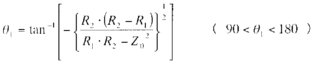
[0025] 位相線路 21は次の式(1)に示す電気長 0 [deg]を有する位相線路で、キャリア増 幅器 3の出力側のインピーダンス基準点 1 1と出力合成点 13の間に接続される。 [0025] The phase line 21 is a phase line having an electrical length of 0 [deg] shown in the following equation (1), and is connected between the impedance reference point 11 on the output side of the carrier amplifier 3 and the output combining point 13. Is done.
[数 1] [Number 1]
ここで、 Ζは位相線路 21 , 23の特性インピーダンスを示す。 Here, Ζ indicates the characteristic impedance of the phase lines 21 and 23.
0 0
また、位相線路 23は次の式(2)に示す電気長 Θ [deg]を有する位相線路であり、 The phase line 23 is a phase line having an electrical length Θ [deg] expressed by the following equation (2):
2 2
ピーク増幅器 7の出力側のインピーダンス基準点 12と出力合成点 13の間に接続さ れる。 Connected between the impedance reference point 12 on the output side of the peak amplifier 7 and the output combining point 13.
[数 2] [Equation 2]
tan ( () < «, < 90 ( 2 )tan (() <«, <90 (2)
さらに、位相線路 22は次の式(3)に示す電気長 Θ [deg]を有する位相線路であり Further, the phase line 22 is a phase line having an electrical length Θ [deg] shown in the following equation (3).
3 Three
、入力分配回路 3とピーク増幅器 7の間に接続される。
θ = θ - θ + θ - θ (3) , Connected between the input distribution circuit 3 and the peak amplifier 7. θ = θ-θ + θ-θ (3)
3 1 2 c ρ 3 1 2 c ρ
[0028] 次に動作について説明する。 Next, the operation will be described.
図 1の入力信号のレベルが小さい場合は、 Β級又は C級バイアスされたピーク増幅 器 7はオフ状態、即ち RF信号を増幅しない状態となり、キャリア増幅器 3からの RF信 号のみが出力合成点 13に出力される。このように、入力信号のレベルが小さい場合 には、ピーク増幅器 7がオフ状態となるため、ピーク増幅器 7の出力側のインピーダン ス基準点 12から見たピーク増幅器 7の出力インピーダンスは、理想的には無限大 (ο pen)となり、また、位相線路 23の電気長 0 は 90° 未満となるため、電気長 0 を有 When the level of the input signal in Fig. 1 is small, the peak amplifier 7 that is biased to class C or class C is turned off, i.e., does not amplify the RF signal, and only the RF signal from the carrier amplifier 3 is the output synthesis point. Is output to 13. In this way, when the level of the input signal is small, the peak amplifier 7 is turned off, so that the output impedance of the peak amplifier 7 viewed from the impedance reference point 12 on the output side of the peak amplifier 7 is ideal. Is infinite (ο pen), and the electrical length 0 of the phase line 23 is less than 90 °.
2 2 する位相線路 23は容量性の開放スタブとして作用する。 The 2 2 phase line 23 acts as a capacitive open stub.
[0029] 従って、出力合成点 13から位相線路 23を見たインピーダンスは、抵抗成分が RZ 2よりも小さぐ容量性リアクタンスを有するインピーダンス Z1に変換される。さらに、電 気長 Θ を有する位相線路 21によるインピーダンス変換作用により、キャリア増幅器 3Accordingly, the impedance of the phase line 23 viewed from the output synthesis point 13 is converted into an impedance Z1 having a capacitive reactance whose resistance component is smaller than RZ2. In addition, the carrier amplifier 3 has an impedance conversion action by the phase line 21 having the electrical length Θ.
1 1
の出力側のインピーダンス基準点 11から出力側を見た負荷インピーダンスは 2Rより も大きい実数抵抗 2R+ aに変換される。 The load impedance seen from the output impedance reference point 11 is converted to a real resistance 2R + a that is greater than 2R.
[0030] 図 2は高効率増幅器の負荷変調の軌跡をスミスチャート上に描いた図である。従来 型のドハティ増幅器では、図 2の点線に示すように、負荷変調の軌跡は RZ2〜2Rと なっているのに対し、この実施の形態 1の高効率増幅器では、図 2の実線に示すよう に、負荷変調の軌跡は Z1〜2R+ aとなっている。 FIG. 2 is a diagram illustrating a load modulation locus of a high efficiency amplifier on a Smith chart. In the conventional Doherty amplifier, the load modulation trajectory is RZ2 to 2R as shown by the dotted line in FIG. 2, whereas in the high efficiency amplifier of the first embodiment, as shown by the solid line in FIG. In addition, the locus of load modulation is Z1 ~ 2R + a.
[0031] 図 3はこの発明の実施の形態 1による高効率増幅器の構成と各部の電気長と、入 力信号のレベルが大きい場合の各部力 見たインピーダンスを示す図であり、図 1と 同符号は同一のものである。図 3において、入力信号のレベルが大きい場合には、 B 級又は C級バイアスされたピーク増幅器 7はオン状態、即ち RF信号を増幅する状態 となるため、出力合成点 13ではキャリア増幅器 3及びピーク増幅器 7からの RF信号 が合成されて出力される。このとき、キャリア増幅器 3の出力側のインピーダンス基準 点 11及びピーク増幅器 7の出力側のインピーダンス基準点 12から出力側を見た負 荷インピーダンスは共に Rとなる。 FIG. 3 is a diagram showing the configuration of the high-efficiency amplifier according to Embodiment 1 of the present invention, the electrical length of each part, and the impedance of each part when the level of the input signal is large. The reference numerals are the same. In FIG. 3, when the level of the input signal is large, the peak amplifier 7 biased with class B or class C is in an on state, that is, a state in which the RF signal is amplified. The RF signal from amplifier 7 is synthesized and output. At this time, the load impedances of the output side viewed from the impedance reference point 11 on the output side of the carrier amplifier 3 and the impedance reference point 12 on the output side of the peak amplifier 7 are both R.
[0032] ここで、予め高効率増幅器では、負荷インピーダンスが 2R+ aのときに、キャリア増 幅器 3では飽和電力は小さいが効率が高くなるように設計し、負荷インピーダンスが
Rのときに、キャリア増幅器 3及びピーク増幅器 7では飽和電力が大きくなるように設 計しておくと、入力信号のレベルが小さい場合には、キャリア増幅器 3が高効率動作 し、入力信号のレベルが大きい場合には、キャリア増幅器 3及びピーク増幅器 7は飽 和電力が大きくなるように動作させることが可能となる。 Here, in the high efficiency amplifier, when the load impedance is 2R + a, the carrier amplifier 3 is designed so that the saturation power is small but the efficiency is high, and the load impedance is When the carrier amplifier 3 and the peak amplifier 7 are designed so that the saturation power is large when R, the carrier amplifier 3 operates at a high efficiency when the input signal level is small, and the input signal level When is large, the carrier amplifier 3 and the peak amplifier 7 can be operated so as to increase the saturated power.
[0033] 以上 2つの作用により、即ち、入力信号のレベルに応じてピーク増幅器 7の出力が キャリア増幅器 3の出力に合成されるという効果、及び入力信号のレベルに応じてキ ャリア増幅器 3及びピーク増幅器 7から出力側を見た負荷インピーダンスが変化する という作用により、この実施の形態 1では、飽和点からの出力バックオフが大きい状態 にお 、て高効率な動作を実現することが可能となる。 [0033] By the above two actions, that is, the effect that the output of the peak amplifier 7 is combined with the output of the carrier amplifier 3 according to the level of the input signal, and the carrier amplifier 3 and the peak according to the level of the input signal. Due to the effect that the load impedance when the output side is viewed from the amplifier 7 is changed, this Embodiment 1 can realize a highly efficient operation in a state where the output back-off from the saturation point is large. .
[0034] 図 4は高効率増幅器の出力電力に対する効率特性を示す図である。ここでは、従 来のドノ、ティ増幅器とこの実施の形態 1の高効率増幅器とを比較している。また、この 実施の形態 1では、入力信号のレベルが小信号カも大信号に推移したときに、キヤリ ァ増幅器 3の出力側のインピーダンス基準点 1 1から出力側を見たインピーダンスが、 実数抵抗 2R + a ( aは正)から Rへと推移するため、図 4に示すように、ドハティ増幅 器としての飽和点 aにカ卩えて、出力バックオフ 6dBの点 bよりも大きい出力バックオフ( 6 + β ) άΒ ( βは正)の点 cにおいて効率最大点を迎えることが可能となる。 FIG. 4 is a diagram showing efficiency characteristics with respect to output power of the high efficiency amplifier. Here, the conventional Dono and Tee amplifiers are compared with the high efficiency amplifier of the first embodiment. In the first embodiment, when the level of the input signal changes from a small signal to a large signal, the impedance viewed from the output impedance reference point 11 of the carrier amplifier 3 is the real resistance. Since the transition from 2R + a (a is positive) to R, as shown in Fig. 4, the output backoff is larger than the point b of the output backoff 6dB in addition to the saturation point a as a Doherty amplifier. 6 + β) άΒ (β is positive) It becomes possible to reach the maximum efficiency point c.
[0035] よって、この実施の形態 1では、入力信号のレベルが小さい場合に、キャリア増幅器 3の出力側のインピーダンス基準点 1 1から出力側を見たインピーダンスを、従来型の ドハティ増幅器のインピーダンス 2Rよりも大きくできるため、その分、 1回目の効率最 大点を従来のドノ、ティ増幅器の出力バックオフ 6dBの点 bよりも出力バックオフの大き い小信号レベルの点 cに設定することが可能となる。つまり、この実施の形態 1では、 出力バックオフが 6dBよりも大きい小信号動作レベルでの高効率化がより効果的とな り、高効率ィ匕を図ることができる。 Therefore, in the first embodiment, when the level of the input signal is small, the impedance viewed from the impedance reference point 11 on the output side of the carrier amplifier 3 as viewed from the output side is set to the impedance 2R of the conventional Doherty amplifier. Therefore, the maximum efficiency point for the first time should be set to the point c of the small signal level where the output back-off is larger than the point b of 6 dB of the output back-off of the conventional Dono-tee amplifier. Is possible. That is, in the first embodiment, high efficiency at a small signal operation level with an output back-off greater than 6 dB becomes more effective, and high efficiency can be achieved.
[0036] この実施の形態 1では、従来のドハティ増幅器と同様に、キャリア増幅器 3の出力側 にオフセット位相線路 4を接続し、ピーク増幅器 7の出力側にオフセット位相線路 8を 接続しているが、オフセット位相線路 4及びオフセット位相線路 8を削除しても良ぐそ の場合に、上記式(3)は次の式 (4)となる。 In the first embodiment, similarly to the conventional Doherty amplifier, the offset phase line 4 is connected to the output side of the carrier amplifier 3 and the offset phase line 8 is connected to the output side of the peak amplifier 7. In the case where the offset phase line 4 and the offset phase line 8 may be deleted, the above equation (3) becomes the following equation (4).
θ = θ - Θ (4)
[0037] このように、この実施の形態 1では、入力分配回路 2は入力信号を 2つの経路 (第 1 及び第 2の経路)に分配し、一方の経路にキャリア増幅器 3を接続し、他方の経路に ピーク増幅器 7を接続し、 2つの経路の出力合成点 13に 90° 位相線路 (インピーダ ンス変換回路) 9を接続し、キャリア増幅器 3の出力側のインピーダンス基準点 11と出 力合成点 13の間に位相線路 (第 1の位相線路) 21を接続し、入力分配回路 2とピー ク増幅器 7の間に位相線路 (第 2の位相線路) 22を接続し、ピーク増幅器 7の出力側 のインピーダンス基準点 12と出力合成点 13の間に位相線路 (第 3の位相線路) 23を 接続し、入力信号のレベルが小さい場合に、キャリア増幅器 3の出力側のインピーダ ンス基準点 11から出力側を見たインピーダンスが 2R+ aとなるように、位相線路 21 の電気長 0 と位相線路 23の電気長 Θ を設定し、位相線路 22の電気長 Θ を位相 θ = θ-Θ (4) Thus, in the first embodiment, the input distribution circuit 2 distributes the input signal to two paths (first and second paths), connects the carrier amplifier 3 to one path, and the other The peak amplifier 7 is connected to the path of, the 90 ° phase line (impedance conversion circuit) 9 is connected to the output combining point 13 of the two paths, the impedance reference point 11 on the output side of the carrier amplifier 3 and the output combining point A phase line (first phase line) 21 is connected between 13, a phase line (second phase line) 22 is connected between the input distribution circuit 2 and the peak amplifier 7, and the output side of the peak amplifier 7 Output from impedance reference point 11 on the output side of carrier amplifier 3 when a phase line (third phase line) 23 is connected between impedance reference point 12 and output combining point 13 and the input signal level is low Phase line so that the impedance seen from the side is 2R + a Set 21 an electrical length Θ electrical length 0 and the phase line 23, the phase of the electrical length Θ of phase line 22
1 2 3 線路 21の電気長 0 と位相線路 23の電気長 0 との差に設定する。 1 2 3 The difference between the electrical length 0 of the line 21 and the electrical length 0 of the phase line 23 is set.
1 2 1 2
[0038] 以上のように、この実施の形態 1によれば、キャリア増幅器 3の出力側のインピーダ ンス基準点 11と出力合成点 13の間に電気長 Θ の位相線路 21を接続し、入力分配 As described above, according to the first embodiment, the phase line 21 having the electrical length Θ is connected between the impedance reference point 11 on the output side of the carrier amplifier 3 and the output combining point 13, and the input distribution is performed.
1 1
回路 2とピーク増幅器 7の間に電気長 Θ の位相線路 22を接続し、ピーク増幅器 7の A phase line 22 of electrical length Θ is connected between the circuit 2 and the peak amplifier 7, and the peak amplifier 7
3 Three
出力側のインピーダンス基準点 12と出力合成点 13の間に電気長 Θ の位相線路 23 Phase line 23 of electrical length Θ between impedance reference point 12 on the output side and output synthesis point 13 23
2 2
を接続し、入力信号レベルが小さい場合に、キャリア増幅器 3の出力側のインピーダ ンス基準点 11から出力側を見たインピーダンスが 2R+ aとなるように、位相線路 21 の電気長 0 と位相線路 23の電気長 Θ を設定し、位相線路 22の電気長 Θ を位相 When the input signal level is small, the electrical length 0 of the phase line 21 and the phase line 23 are set so that the impedance viewed from the impedance reference point 11 on the output side of the carrier amplifier 3 is 2R + a. The electrical length Θ of the phase line 22
1 2 3 線路 21の電気長 Θ と位相線路 23の電気長 Θ との差に設定することにより、効率を 1 2 3 Efficiency is reduced by setting the difference between the electrical length Θ of line 21 and the electrical length Θ of phase line 23.
1 2 1 2
最大にする出カノックオフを 6dBより大きくすることができ、出力バックオフが 6dBより も大き 、小信号動作レベルにぉ 、て効率を向上させることができると!/、う効果が得ら れる。 The maximum output can knock-off can be greater than 6 dB, the output back-off is greater than 6 dB, and the efficiency can be improved for small signal operation levels.
[0039] 実施の形態 2. [0039] Embodiment 2.
図 5はこの発明の実施の形態 2による高効率増幅器の構成と各部の電気長と、入 力信号のレベルが小さい場合の各部力も見たインピーダンスを示す図である。図 5に 示す高効率増幅器は、上記実施の形態 1の図 1に示す高効率増幅器に位相線路( 第 4の位相線路) 24を追加したものであり、その他の構成は図 1と同じである。 FIG. 5 is a diagram showing the configuration of the high efficiency amplifier according to Embodiment 2 of the present invention, the electrical length of each part, and the impedance of each part when the level of the input signal is small. The high-efficiency amplifier shown in FIG. 5 is obtained by adding a phase line (fourth phase line) 24 to the high-efficiency amplifier shown in FIG. 1 of the first embodiment, and the other configurations are the same as those in FIG. .
また、図 6はこの発明の実施の形態 2による高効率増幅器の構成と各部の電気長と
、入力信号のレベルが大きい場合の各部から見たインピーダンスを示す図である。図FIG. 6 shows the configuration of the high efficiency amplifier according to Embodiment 2 of the present invention and the electrical length of each part. It is a figure which shows the impedance seen from each part in case the level of an input signal is large. Figure
6に示す高効率増幅器は、上記実施の形態 1の図 3に示す高効率増幅器に位相線 路 24を追カ卩したものであり、その他の構成は図 3と同じである。 The high-efficiency amplifier shown in FIG. 6 is obtained by adding a phase line 24 to the high-efficiency amplifier shown in FIG. 3 of the first embodiment, and the other configurations are the same as those in FIG.
[0040] 位相線路 24は次の式(5)に示す電気長 Δ Θ [deg]を有する位相線路であり、入力 分配回路 3とピーク増幅器 6の間に接続される。 The phase line 24 is a phase line having an electrical length ΔΘ [deg] shown in the following equation (5), and is connected between the input distribution circuit 3 and the peak amplifier 6.
A θ = θ - θ (5) A θ = θ-θ (5)
CA PA CA PA
ここで、 Θ はキャリア増幅器 3の電気長であり、 Θ はピーク増幅器 7の電気長で Where Θ is the electrical length of the carrier amplifier 3, and Θ is the electrical length of the peak amplifier 7.
CA ΡΑ CA ΡΑ
ある。 is there.
[0041] 次に動作について説明する。 Next, the operation will be described.
図 6において、入力信号のレベルが大きい場合には、 Β級又は C級バイアスされた ピーク増幅器 7はオン状態、即ち RF信号を増幅する状態となるため、出力合成点 13 ではキャリア増幅器 3及びピーク増幅器 7からの RF信号が合成されて出力される。 In FIG. 6, when the level of the input signal is large, the peak amplifier 7 that is biased to class B or class C is in an on state, that is, a state in which the RF signal is amplified. The RF signal from the amplifier 7 is synthesized and output.
[0042] このとき、この実施の形態 2では、 Α級又は ΑΒ級バイアスされたキャリア増幅器 3の 電気長 Θ と B級又は C級ノィァスされたピーク増幅器 7の電気長 Θ との差 Δ Θが At this time, in the second embodiment, the difference ΔΘ between the electrical length Θ of the carrier amplifier 3 that is class-class or class-classically biased and the electrical length Θ of the peak amplifier 7 that is class B or class C-noised is
CA CA CA CA
、ピーク増幅器 7の入力側に接続された位相線路 24により補正されるので、キャリア 増幅器 3とピーク増幅器 7からの RF信号が出力合成点 13において同位相で合成す ることが可能となる。このため、入力信号レベルが大きい領域での RF信号の合成効 率が向上する。 Since the correction is made by the phase line 24 connected to the input side of the peak amplifier 7, the RF signals from the carrier amplifier 3 and the peak amplifier 7 can be synthesized in the same phase at the output synthesis point 13. For this reason, the RF signal synthesis efficiency is improved in the region where the input signal level is high.
[0043] 図 7は高効率増幅器の出力電力に対する効率特性を示している。ここでは、従来の ドハティ増幅器と上記実施の形態 1の高効率増幅器とこの実施の形態 2の高効率増 幅器とを比較している。図 7に示すように、この実施の形態 2では、上記実施の形態 1 と比較して、入力信号のレベルが大きい領域での RF信号の合成効率が向上し、結 果として増幅器の高効率ィ匕を図ることが可能となる。 FIG. 7 shows the efficiency characteristic with respect to the output power of the high efficiency amplifier. Here, the conventional Doherty amplifier, the high efficiency amplifier of the first embodiment, and the high efficiency amplifier of the second embodiment are compared. As shown in FIG. 7, in the second embodiment, compared with the first embodiment, the RF signal synthesis efficiency in the region where the level of the input signal is large is improved, and as a result, the high efficiency of the amplifier is improved. It is possible to make a habit.
その他の動作については上記実施の形態 1と同じである。 Other operations are the same as those in the first embodiment.
[0044] この実施の形態 2では、従来のドハティ増幅器と同様に、キャリア増幅器 3の出力側 にオフセット位相線路 4を接続し、ピーク増幅器 7の出力側にオフセット位相線路 8を 接続して 、るが、オフセット位相線路 4及びオフセット位相線路 8を削除しても良 、。 In the second embodiment, similarly to the conventional Doherty amplifier, the offset phase line 4 is connected to the output side of the carrier amplifier 3 and the offset phase line 8 is connected to the output side of the peak amplifier 7. However, the offset phase line 4 and the offset phase line 8 may be deleted.
[0045] 以上のように、この実施の形態 2によれば、上記実施の形態 1と同様の効果が得ら
れると共に、ピーク増幅器 7の入力側に接続された位相線路 24により、キャリア増幅 器 3の電気長 Θ とピーク増幅器 7の電気長 Θ との差を補正することにより、さらに [0045] As described above, according to the second embodiment, the same effect as in the first embodiment can be obtained. Further, by correcting the difference between the electrical length Θ of the carrier amplifier 3 and the electrical length Θ of the peak amplifier 7 by the phase line 24 connected to the input side of the peak amplifier 7,
CA CA CA CA
効率を向上させることができると 、う効果が得られる。 If the efficiency can be improved, the effect can be obtained.
[0046] 実施の形態 3. [0046] Embodiment 3.
図 8はこの発明の実施の形態 3による高効率増幅器の構成と各部の電気長と、入 力信号のレベルが小さい場合の各部力も見たインピーダンスを示す図である。図 8に 示す高効率増幅器は、上記実施の形態 1の図 1に示す高効率増幅器における 90° 位相回路 9の出力側に、特性インピーダンス Rを有するアイソレータ 31を追加したも のであり、その他の構成は図 1と同じである。 FIG. 8 is a diagram showing the configuration of the high efficiency amplifier according to Embodiment 3 of the present invention, the electrical length of each part, and the impedance of each part when the level of the input signal is small. The high efficiency amplifier shown in FIG. 8 is obtained by adding an isolator 31 having a characteristic impedance R to the output side of the 90 ° phase circuit 9 in the high efficiency amplifier shown in FIG. Is the same as in Figure 1.
[0047] 次に動作について説明する。 Next, the operation will be described.
図 8において、 90° 位相回路 9の出力側に接続された特性インピーダンス Rを有す るアイソレータ 31により、出力合成点 13から見た負荷インピーダンス力 ¾Z2に確定 される。このため、高効率増幅器は出力端子 10以降の回路状態によらず、安定的に 高効率率な動作をすることが可能になる。 In FIG. 8, an isolator 31 having a characteristic impedance R connected to the output side of the 90 ° phase circuit 9 determines the load impedance force ¾Z2 viewed from the output synthesis point 13. Therefore, the high-efficiency amplifier can stably operate with high efficiency regardless of the circuit state after the output terminal 10.
[0048] 図 9はアイソレータ 31の周波数特性を示す図である。アイソレータ 31は、図 9に示 すように、 RF信号の周波数 f に対して、 RF信号の高調波、例えば 2倍の周波数 2f FIG. 9 is a diagram showing the frequency characteristics of the isolator 31. As shown in FIG. 9, the isolator 31 has a frequency 2f that is a harmonic of the RF signal, for example, twice the frequency f of the RF signal.
0 0 を使用帯域外とする周波数特性を持っており、高調波の発生を抑圧することができる Has a frequency characteristic that makes 0 0 outside the use band, and can suppress the generation of harmonics.
[0049] この実施の形態 3では、従来のドハティ増幅器と同様に、キャリア増幅器 3の出力側 にオフセット位相線路 4を接続し、ピーク増幅器 7の出力側にオフセット位相線路 8を 接続して 、るが、オフセット位相線路 4及びオフセット位相線路 8を削除しても良 、。 [0049] In the third embodiment, similarly to the conventional Doherty amplifier, the offset phase line 4 is connected to the output side of the carrier amplifier 3, and the offset phase line 8 is connected to the output side of the peak amplifier 7. However, the offset phase line 4 and the offset phase line 8 may be deleted.
[0050] 以上のように、この実施の形態 3によれば、上記実施の形態 1と同様の効果が得ら れると共に、 90° 位相回路 9の出力側に特性インピーダンス Rを有するアイソレータ 3 1を接続することにより、安定的に高効率率な動作をすることができ、高調波の発生を 抑圧することができると!/、う効果が得られる。 As described above, according to the third embodiment, an effect similar to that of the first embodiment can be obtained, and an isolator 31 having a characteristic impedance R can be provided on the output side of the 90 ° phase circuit 9. By connecting, stable and high-efficiency operation can be achieved, and the generation of harmonics can be suppressed!
[0051] 実施の形態 4. [0051] Embodiment 4.
図 10はこの発明の実施の形態 4による高効率増幅器におけるキャリア増幅器 3及 びピーク増幅器 7の内部構成を示すブロック図である。図 10に示すキャリア増幅器 3
及びピーク増幅器 7は、入力端子 41、基本波整合回路 42、電源端子 43、ノィァス 回路 44、トランジスタ (増幅素子) 45、位相線路 (第 5の位相線路) 46、電源端子 47、 コンデンサ 48、 90° 位相線路 49、基本波整合回路 50及び出力端子 51を備えてい る。 FIG. 10 is a block diagram showing the internal configuration of carrier amplifier 3 and peak amplifier 7 in the high efficiency amplifier according to Embodiment 4 of the present invention. Carrier amplifier 3 shown in Figure 10 The peak amplifier 7 includes an input terminal 41, a fundamental matching circuit 42, a power supply terminal 43, a noise circuit 44, a transistor (amplifying element) 45, a phase line (fifth phase line) 46, a power supply terminal 47, capacitors 48, 90. ° Phase line 49, fundamental wave matching circuit 50, and output terminal 51 are provided.
[0052] 次に動作について説明する。 Next, the operation will be described.
図 10において、トランジスタ 45の入力側には、電源端子 43からのバイアス電圧が バイアス回路 44を介して供給される。また、コンデンサ 48及び 90° 位相線路 49によ り、トランジスタ 45の出力側のバイアス回路を構成し、電源端子 47からのバイアス電 圧は、位相線路 49及び位相線路 46を介して、トランジスタ 45の出力側に供給される 。入力端子 41から入力された RF信号は、基本波整合回路 42を介してトランジスタ 4 5で増幅され、位相線路 46及び基本波整合回路 50を介して出力端子 51より出力さ れる。 In FIG. 10, the bias voltage from the power supply terminal 43 is supplied to the input side of the transistor 45 via the bias circuit 44. Also, the capacitor 48 and the 90 ° phase line 49 constitute a bias circuit on the output side of the transistor 45, and the bias voltage from the power supply terminal 47 is connected to the transistor 45 via the phase line 49 and the phase line 46. Supplied to the output side. The RF signal input from the input terminal 41 is amplified by the transistor 45 via the fundamental wave matching circuit 42 and output from the output terminal 51 via the phase line 46 and the fundamental wave matching circuit 50.
[0053] コンデンサ 48は RF信号の周波数 fで、十分に小さ!/、インピーダンスとなるような容 [0053] Capacitor 48 is sufficiently small at the frequency f of the RF signal!
0 0
量を有するものとし、 90° 位相線路 49と電源端子 47の間に RF信号の周波数 fで短 The 90 ° phase line 49 and the power supply terminal 47 are short at the frequency f of the RF signal.
0 絡点を形成している。 90° 位相線路 49は RF信号の周波数 fで電気長が 90° の長 0 An entanglement point is formed. 90 ° phase line 49 is RF signal frequency f and electrical length is 90 °
0 0
さの短絡スタブとすると、 RF信号の 2倍の周波数 2fでは電気長が 180° の長さとな If the short-circuit stub is, the electrical length is 180 ° at the frequency 2f, which is twice the RF signal.
0 0
り、位相線路 46と 90° 位相線路 49の間に RF信号の 2倍の周波数 2f における短絡 Short between the phase line 46 and the 90 ° phase line 49 at a frequency 2f that is twice the RF signal.
0 0
点が形成される。 A point is formed.
[0054] 位相線路 46の電気長 Θ の長さを変えると、トランジスタ 45から見た 2倍の周波数 2f [0054] When the length of the electrical length Θ of the phase line 46 is changed, the frequency 2f as seen from the transistor 45 is doubled.
0 0
における短絡点までの距離が変わるため、トランジスタ 45から出力側を見た 2倍の周 Because the distance to the short-circuit point in the
0 0
波数 2f におけるインピーダンス ZL (2f )が変化する。一般に増幅器の効率は 2倍の Impedance ZL (2f) at wave number 2f changes. Generally, amplifier efficiency is double
0 0 0 0
周波数におけるインピーダンスに対する依存性があるため、位相線路 46の電気長 Θ を最適化することにより、 RF信号の 2倍の周波数 2fの高調波の発生を抑圧し、キヤ Because there is a dependency on the impedance in frequency, optimizing the electrical length Θ of the phase line 46 suppresses the generation of harmonics of the frequency 2f, which is twice the RF signal,
0 0 0 0
リア増幅器 3及びピーク増幅器 7の効率を最大化することが可能である。 The efficiency of the rear amplifier 3 and the peak amplifier 7 can be maximized.
[0055] 図 11は位相線路 46の電気長 0 に対するキャリア増幅器 3及びピーク増幅器 7の FIG. 11 shows the carrier amplifier 3 and the peak amplifier 7 with respect to the electric length 0 of the phase line 46.
0 0
効率特性を示す図であり、位相線路 46の電気長 Θ を最適の値 Θ にすることによ It is a graph showing the efficiency characteristics, and the electrical length Θ of the phase line 46 is set to the optimum value Θ.
0 OPT 0 OPT
り、 RF信号の 2倍の周波数 2fの高調波の発生を抑圧し、キャリア増幅器 3及びピー This suppresses the generation of harmonics with a frequency 2f that is twice that of the RF signal.
0 0
ク増幅器 7の効率 E を得ることができる。
[0056] このように、キャリア増幅器 3及びピーク増幅器 7の効率を最大化することで、高効 率増幅器全体としての効率を最大化することができ、出力バックオフが大き 、小信号 レベルにおいても効率を向上させることが可能となる。 The efficiency E of the amplifier 7 can be obtained. Thus, by maximizing the efficiency of the carrier amplifier 3 and the peak amplifier 7, the efficiency of the entire high efficiency amplifier can be maximized, the output back-off is large, and even at a small signal level. Efficiency can be improved.
[0057] 以上のように、この実施の形態 4によれば、上記実施の形態 1と同様の効果が得ら れると共に、キャリア増幅器 3及びピーク増幅器 7のトランジスタ 45のバイアス電圧を、 RF信号の周波数 fで電気長が 90° の長さの短絡スタブとなる 90° 位相線路 49と位 As described above, according to the fourth embodiment, the same effects as those of the first embodiment can be obtained, and the bias voltages of the transistors 45 of the carrier amplifier 3 and the peak amplifier 7 can be changed with respect to the RF signal. 90 ° phase line 49, which is a short-circuited stub with an electrical length of 90 ° at frequency f
0 0
相線路 46を介して供給し、位相線路 46の電気長 Θ を、 RF信号の 2倍の周波数 2f Is supplied via the phase line 46, and the electrical length Θ of the phase line 46 is set to a frequency 2f that is twice the RF signal.
0 0 の高調波を削減し、キャリア増幅器 3及びピーク増幅器 7の効率を最大化する値に設 定することにより、出力バックオフが大きい小信号レベルにおいても効率を向上させ ることができると!/、う効果が得られる。 By reducing the 0 0 harmonics and setting the values to maximize the efficiency of the carrier amplifier 3 and the peak amplifier 7, the efficiency can be improved even at small signal levels with large output backoff! /, The effect is obtained.
[0058] 実施の形態 5. [0058] Embodiment 5.
図 12はこの発明の実施の形態 5による高効率増幅器の構成と各部の電気長を示 す図である。図 12に示す高効率増幅器は、上記実施の形態 1の図 1に示す高効率 増幅器において、キャリア増幅器 3に接続されたゲート電圧発生回路 61及びドレイン 電圧発生回路 62、ピーク増幅器 7に接続されたゲート電圧発生回路 63及びドレイン 電圧発生回路 64を追加したものであり、その他の構成は図 1と同じである。 FIG. 12 is a diagram showing the configuration of the high efficiency amplifier according to the fifth embodiment of the present invention and the electrical length of each part. The high-efficiency amplifier shown in FIG. 12 is the same as the high-efficiency amplifier shown in FIG. 1 of Embodiment 1 above, but is connected to the gate voltage generation circuit 61, the drain voltage generation circuit 62, and the peak amplifier 7 connected to the carrier amplifier 3. A gate voltage generation circuit 63 and a drain voltage generation circuit 64 are added, and other configurations are the same as those in FIG.
[0059] 図 12において、キャリア増幅器 3及びピーク増幅器 7では、同じバイアス電圧を供 給した場合に同じ飽和電力を有するトランジスタ(図示せず)を使用しているものとす る。また、ドレイン電圧発生回路 62がキャリア増幅器 3のトランジスタに供給するバイ ァス電圧 Vdlは、ドレイン電圧発生回路 64がピーク増幅器 7のトランジスタに供給す るバイアス電圧 Vd2よりも小さく設定されている。そのため、キャリア増幅器 3の飽和 電力はピーク増幅器 7の飽和電力よりも小さくなり、上記実施の形態 1よりも大きな出 力バックオフ点で効率最大点を迎えることが可能となる。 In FIG. 12, it is assumed that the carrier amplifier 3 and the peak amplifier 7 use transistors (not shown) having the same saturation power when the same bias voltage is supplied. The bias voltage Vdl supplied from the drain voltage generation circuit 62 to the transistor of the carrier amplifier 3 is set smaller than the bias voltage Vd2 supplied from the drain voltage generation circuit 64 to the transistor of the peak amplifier 7. Therefore, the saturation power of the carrier amplifier 3 is smaller than the saturation power of the peak amplifier 7, and the maximum efficiency point can be reached at a larger output back-off point than in the first embodiment.
[0060] 図 13は高効率増幅器の出力電力に対する効率特性を示す図である。ここでは、上 記実施の形態 1の高効率増幅器とこの実施の形態 5の高効率増幅器とを比較してい る。図 13に示すように、ドノ、ティ増幅器としての飽和点 aにカ卩えて、出力バックオフ(6 + j8 ) dBの点 cよりも大きい出力バックオフ(6 + j8 + γ ) dB ( j8 , γは正)の点 dにお V、て効率最大点を迎えることが可能となる。
[0061] 以上のように、この実施の形態 5によれば、キャリア増幅器 3のトランジスタのドレイン に供給するノ ィァス電圧 Vdlを、ピーク増幅器 7のトランジスタのドレインに供給する ノィァス電圧 Vd2よりも小さく設定することにより、上記実施の形態 1よりも、効率を最 大にする出カノックオフを 6dBより大きくすることができ、出力バックオフが 6dBよりも 大き 、小信号動作レベルにぉ 、て効率をさらに向上させることができると 、う効果が 得られる。 FIG. 13 is a diagram showing efficiency characteristics with respect to output power of the high efficiency amplifier. Here, the high efficiency amplifier of the first embodiment and the high efficiency amplifier of the fifth embodiment are compared. As shown in Fig. 13, the output back-off (6 + j8 + γ) dB (j8) is larger than the point c of the output back-off (6 + j8) dB in addition to the saturation point a as a Dono and tee amplifier. , γ is positive) V can reach the maximum efficiency point d. As described above, according to the fifth embodiment, the noise voltage Vdl supplied to the drain of the transistor of the carrier amplifier 3 is smaller than the noise voltage Vd 2 supplied to the drain of the transistor of the peak amplifier 7. By setting, the output cannock-off for maximizing the efficiency can be made larger than 6 dB compared to the first embodiment, the output back-off is larger than 6 dB, and the efficiency can be further improved with the small signal operation level. If it can be improved, the effect can be obtained.
産業上の利用可能性 Industrial applicability
[0062] 以上のように、この発明に係る高効率増幅器は、例えば効率を最大にする出力バッ クオフを 6dBより大きくし、出力バックオフが 6dBよりも大きい小信号動作レベルにお V、て効率を向上させるものに適して!/、る。
[0062] As described above, the high-efficiency amplifier according to the present invention has, for example, an output back-off that maximizes the efficiency greater than 6dB, and the output back-off is less than 6dB. Suitable for things that improve!