WO2006136543A2 - Infrared absorbing dye - Google Patents
Infrared absorbing dye Download PDFInfo
- Publication number
- WO2006136543A2 WO2006136543A2 PCT/EP2006/063327 EP2006063327W WO2006136543A2 WO 2006136543 A2 WO2006136543 A2 WO 2006136543A2 EP 2006063327 W EP2006063327 W EP 2006063327W WO 2006136543 A2 WO2006136543 A2 WO 2006136543A2
- Authority
- WO
- WIPO (PCT)
- Prior art keywords
- optionally substituted
- group
- independently
- dye
- hydrocarbon group
- Prior art date
Links
- 0 C/C(/C=C/C=C/C=C1)=C1\N(*)C(C1C(C2)C2C1)/C(/N)=C(/C*C1)\C(N)=C1/C(/N)=C(/C(*(/C(/C=C/C=C/C=C/C1)=C1\[N+]N)I)=C)\N Chemical compound C/C(/C=C/C=C/C=C1)=C1\N(*)C(C1C(C2)C2C1)/C(/N)=C(/C*C1)\C(N)=C1/C(/N)=C(/C(*(/C(/C=C/C=C/C=C/C1)=C1\[N+]N)I)=C)\N 0.000 description 8
- IKUAHCTZJIOYSL-DDFIABBMSA-N CC(C)(C(/C(/N)=C(\C)/N)=[IH])C(C=CC=CC=CC=C1)=C1NN Chemical compound CC(C)(C(/C(/N)=C(\C)/N)=[IH])C(C=CC=CC=CC=C1)=C1NN IKUAHCTZJIOYSL-DDFIABBMSA-N 0.000 description 1
- UZEKKKUXWXEEBH-UHFFFAOYSA-O CC1(C)c(cccc2)c2[N+](CCCCS(O)(=O)=O)=C1/C=C/C(CC/C1=C\C=C(/C2(C)C)\N(CCCCS(O)(=O)=O)c3c2cccc3)=C1N(C)S(c1ccc(C)cc1)(=O)=O Chemical compound CC1(C)c(cccc2)c2[N+](CCCCS(O)(=O)=O)=C1/C=C/C(CC/C1=C\C=C(/C2(C)C)\N(CCCCS(O)(=O)=O)c3c2cccc3)=C1N(C)S(c1ccc(C)cc1)(=O)=O UZEKKKUXWXEEBH-UHFFFAOYSA-O 0.000 description 1
Classifications
-
- B—PERFORMING OPERATIONS; TRANSPORTING
- B41—PRINTING; LINING MACHINES; TYPEWRITERS; STAMPS
- B41C—PROCESSES FOR THE MANUFACTURE OR REPRODUCTION OF PRINTING SURFACES
- B41C1/00—Forme preparation
- B41C1/10—Forme preparation for lithographic printing; Master sheets for transferring a lithographic image to the forme
- B41C1/1008—Forme preparation for lithographic printing; Master sheets for transferring a lithographic image to the forme by removal or destruction of lithographic material on the lithographic support, e.g. by laser or spark ablation; by the use of materials rendered soluble or insoluble by heat exposure, e.g. by heat produced from a light to heat transforming system; by on-the-press exposure or on-the-press development, e.g. by the fountain of photolithographic materials
-
- C—CHEMISTRY; METALLURGY
- C09—DYES; PAINTS; POLISHES; NATURAL RESINS; ADHESIVES; COMPOSITIONS NOT OTHERWISE PROVIDED FOR; APPLICATIONS OF MATERIALS NOT OTHERWISE PROVIDED FOR
- C09B—ORGANIC DYES OR CLOSELY-RELATED COMPOUNDS FOR PRODUCING DYES, e.g. PIGMENTS; MORDANTS; LAKES
- C09B59/00—Artificial dyes of unknown constitution
-
- B—PERFORMING OPERATIONS; TRANSPORTING
- B41—PRINTING; LINING MACHINES; TYPEWRITERS; STAMPS
- B41C—PROCESSES FOR THE MANUFACTURE OR REPRODUCTION OF PRINTING SURFACES
- B41C1/00—Forme preparation
- B41C1/10—Forme preparation for lithographic printing; Master sheets for transferring a lithographic image to the forme
- B41C1/1008—Forme preparation for lithographic printing; Master sheets for transferring a lithographic image to the forme by removal or destruction of lithographic material on the lithographic support, e.g. by laser or spark ablation; by the use of materials rendered soluble or insoluble by heat exposure, e.g. by heat produced from a light to heat transforming system; by on-the-press exposure or on-the-press development, e.g. by the fountain of photolithographic materials
- B41C1/1025—Forme preparation for lithographic printing; Master sheets for transferring a lithographic image to the forme by removal or destruction of lithographic material on the lithographic support, e.g. by laser or spark ablation; by the use of materials rendered soluble or insoluble by heat exposure, e.g. by heat produced from a light to heat transforming system; by on-the-press exposure or on-the-press development, e.g. by the fountain of photolithographic materials using materials comprising a polymeric matrix containing a polymeric particulate material, e.g. hydrophobic heat coalescing particles
-
- B—PERFORMING OPERATIONS; TRANSPORTING
- B41—PRINTING; LINING MACHINES; TYPEWRITERS; STAMPS
- B41C—PROCESSES FOR THE MANUFACTURE OR REPRODUCTION OF PRINTING SURFACES
- B41C1/00—Forme preparation
- B41C1/10—Forme preparation for lithographic printing; Master sheets for transferring a lithographic image to the forme
- B41C1/1041—Forme preparation for lithographic printing; Master sheets for transferring a lithographic image to the forme by modification of the lithographic properties without removal or addition of material, e.g. by the mere generation of a lithographic pattern
-
- B—PERFORMING OPERATIONS; TRANSPORTING
- B41—PRINTING; LINING MACHINES; TYPEWRITERS; STAMPS
- B41M—PRINTING, DUPLICATING, MARKING, OR COPYING PROCESSES; COLOUR PRINTING
- B41M5/00—Duplicating or marking methods; Sheet materials for use therein
- B41M5/26—Thermography ; Marking by high energetic means, e.g. laser otherwise than by burning, and characterised by the material used
- B41M5/40—Thermography ; Marking by high energetic means, e.g. laser otherwise than by burning, and characterised by the material used characterised by the base backcoat, intermediate, or covering layers, e.g. for thermal transfer dye-donor or dye-receiver sheets; Heat, radiation filtering or absorbing means or layers; combined with other image registration layers or compositions; Special originals for reproduction by thermography
- B41M5/46—Thermography ; Marking by high energetic means, e.g. laser otherwise than by burning, and characterised by the material used characterised by the base backcoat, intermediate, or covering layers, e.g. for thermal transfer dye-donor or dye-receiver sheets; Heat, radiation filtering or absorbing means or layers; combined with other image registration layers or compositions; Special originals for reproduction by thermography characterised by the light-to-heat converting means; characterised by the heat or radiation filtering or absorbing means or layers
- B41M5/465—Infra-red radiation-absorbing materials, e.g. dyes, metals, silicates, C black
-
- C—CHEMISTRY; METALLURGY
- C09—DYES; PAINTS; POLISHES; NATURAL RESINS; ADHESIVES; COMPOSITIONS NOT OTHERWISE PROVIDED FOR; APPLICATIONS OF MATERIALS NOT OTHERWISE PROVIDED FOR
- C09B—ORGANIC DYES OR CLOSELY-RELATED COMPOUNDS FOR PRODUCING DYES, e.g. PIGMENTS; MORDANTS; LAKES
- C09B23/00—Methine or polymethine dyes, e.g. cyanine dyes
- C09B23/0066—Methine or polymethine dyes, e.g. cyanine dyes the polymethine chain being part of a carbocyclic ring,(e.g. benzene, naphtalene, cyclohexene, cyclobutenene-quadratic acid)
-
- C—CHEMISTRY; METALLURGY
- C09—DYES; PAINTS; POLISHES; NATURAL RESINS; ADHESIVES; COMPOSITIONS NOT OTHERWISE PROVIDED FOR; APPLICATIONS OF MATERIALS NOT OTHERWISE PROVIDED FOR
- C09B—ORGANIC DYES OR CLOSELY-RELATED COMPOUNDS FOR PRODUCING DYES, e.g. PIGMENTS; MORDANTS; LAKES
- C09B23/00—Methine or polymethine dyes, e.g. cyanine dyes
- C09B23/0091—Methine or polymethine dyes, e.g. cyanine dyes having only one heterocyclic ring at one end of the methine chain, e.g. hemicyamines, hemioxonol
-
- C—CHEMISTRY; METALLURGY
- C09—DYES; PAINTS; POLISHES; NATURAL RESINS; ADHESIVES; COMPOSITIONS NOT OTHERWISE PROVIDED FOR; APPLICATIONS OF MATERIALS NOT OTHERWISE PROVIDED FOR
- C09B—ORGANIC DYES OR CLOSELY-RELATED COMPOUNDS FOR PRODUCING DYES, e.g. PIGMENTS; MORDANTS; LAKES
- C09B23/00—Methine or polymethine dyes, e.g. cyanine dyes
- C09B23/02—Methine or polymethine dyes, e.g. cyanine dyes the polymethine chain containing an odd number of >CH- or >C[alkyl]- groups
- C09B23/08—Methine or polymethine dyes, e.g. cyanine dyes the polymethine chain containing an odd number of >CH- or >C[alkyl]- groups more than three >CH- groups, e.g. polycarbocyanines
- C09B23/083—Methine or polymethine dyes, e.g. cyanine dyes the polymethine chain containing an odd number of >CH- or >C[alkyl]- groups more than three >CH- groups, e.g. polycarbocyanines five >CH- groups
-
- C—CHEMISTRY; METALLURGY
- C09—DYES; PAINTS; POLISHES; NATURAL RESINS; ADHESIVES; COMPOSITIONS NOT OTHERWISE PROVIDED FOR; APPLICATIONS OF MATERIALS NOT OTHERWISE PROVIDED FOR
- C09B—ORGANIC DYES OR CLOSELY-RELATED COMPOUNDS FOR PRODUCING DYES, e.g. PIGMENTS; MORDANTS; LAKES
- C09B23/00—Methine or polymethine dyes, e.g. cyanine dyes
- C09B23/02—Methine or polymethine dyes, e.g. cyanine dyes the polymethine chain containing an odd number of >CH- or >C[alkyl]- groups
- C09B23/08—Methine or polymethine dyes, e.g. cyanine dyes the polymethine chain containing an odd number of >CH- or >C[alkyl]- groups more than three >CH- groups, e.g. polycarbocyanines
- C09B23/086—Methine or polymethine dyes, e.g. cyanine dyes the polymethine chain containing an odd number of >CH- or >C[alkyl]- groups more than three >CH- groups, e.g. polycarbocyanines more than five >CH- groups
-
- C—CHEMISTRY; METALLURGY
- C09—DYES; PAINTS; POLISHES; NATURAL RESINS; ADHESIVES; COMPOSITIONS NOT OTHERWISE PROVIDED FOR; APPLICATIONS OF MATERIALS NOT OTHERWISE PROVIDED FOR
- C09B—ORGANIC DYES OR CLOSELY-RELATED COMPOUNDS FOR PRODUCING DYES, e.g. PIGMENTS; MORDANTS; LAKES
- C09B23/00—Methine or polymethine dyes, e.g. cyanine dyes
- C09B23/10—The polymethine chain containing an even number of >CH- groups
-
- B—PERFORMING OPERATIONS; TRANSPORTING
- B41—PRINTING; LINING MACHINES; TYPEWRITERS; STAMPS
- B41C—PROCESSES FOR THE MANUFACTURE OR REPRODUCTION OF PRINTING SURFACES
- B41C2210/00—Preparation or type or constituents of the imaging layers, in relation to lithographic printing forme preparation
- B41C2210/04—Negative working, i.e. the non-exposed (non-imaged) areas are removed
-
- B—PERFORMING OPERATIONS; TRANSPORTING
- B41—PRINTING; LINING MACHINES; TYPEWRITERS; STAMPS
- B41C—PROCESSES FOR THE MANUFACTURE OR REPRODUCTION OF PRINTING SURFACES
- B41C2210/00—Preparation or type or constituents of the imaging layers, in relation to lithographic printing forme preparation
- B41C2210/06—Developable by an alkaline solution
-
- B—PERFORMING OPERATIONS; TRANSPORTING
- B41—PRINTING; LINING MACHINES; TYPEWRITERS; STAMPS
- B41C—PROCESSES FOR THE MANUFACTURE OR REPRODUCTION OF PRINTING SURFACES
- B41C2210/00—Preparation or type or constituents of the imaging layers, in relation to lithographic printing forme preparation
- B41C2210/08—Developable by water or the fountain solution
-
- B—PERFORMING OPERATIONS; TRANSPORTING
- B41—PRINTING; LINING MACHINES; TYPEWRITERS; STAMPS
- B41C—PROCESSES FOR THE MANUFACTURE OR REPRODUCTION OF PRINTING SURFACES
- B41C2210/00—Preparation or type or constituents of the imaging layers, in relation to lithographic printing forme preparation
- B41C2210/22—Preparation or type or constituents of the imaging layers, in relation to lithographic printing forme preparation characterised by organic non-macromolecular additives, e.g. dyes, UV-absorbers, plasticisers
-
- B—PERFORMING OPERATIONS; TRANSPORTING
- B41—PRINTING; LINING MACHINES; TYPEWRITERS; STAMPS
- B41C—PROCESSES FOR THE MANUFACTURE OR REPRODUCTION OF PRINTING SURFACES
- B41C2210/00—Preparation or type or constituents of the imaging layers, in relation to lithographic printing forme preparation
- B41C2210/24—Preparation or type or constituents of the imaging layers, in relation to lithographic printing forme preparation characterised by a macromolecular compound or binder obtained by reactions involving carbon-to-carbon unsaturated bonds, e.g. acrylics, vinyl polymers
Definitions
- the present invention relates to an infrared absorbing dye as defined in claim 1.
- the present invention relates also to a heat-sensitive imaging element comprising said IR dye and more particularly to a heat-sensitive lithographic printing plate precursor comprising said IR dye.
- the present invention relates also to a method for making a lithographic printing plate whereby a print-out image of high contrast is formed upon exposure to IR- radiation.
- Lithographic printing typically involves the use of a so-called printing master such as a printing plate which is mounted on a cylinder of a rotary printing press.
- the master carries a lithographic image on its surface and a print is obtained by applying ink to said image and then transferring the ink from the master onto a receiver material, which is typically paper.
- ink as well as an aqueous fountain solution also called dampening liquid
- the lithographic image which consists of oleophilic (or hydrophobic, i.e. ink-accepting, water-repelling) areas as well as hydrophilic (or oleophobic, i.e. water-accepting, ink-repelling) areas.
- so- called driographic printing the lithographic image consists of ink- accepting and ink-abhesive (ink-repelling) areas and during driographic printing, only ink is supplied to the master.
- a typical positive-working plate precursor comprises a hydrophilic support and an oleophilic coating which is not readily soluble in an aqueous alkaline developer in the non-exposed state and becomes soluble in the developer after exposure to radiation.
- heat-sensitive printing plate precursors have become very popular. Such thermal materials offer the advantage of daylight stability and are especially used in the so-called computer-to-plate method (CtP) wherein the plate precursor is directly exposed, i.e. without the use of a film mask.
- the material is exposed to heat or to infrared radiation and the generated heat triggers a (physico-) chemical process, such as ablation, polymerization, insolubilization by cross-linking of a polymer or by particle coagulation of a thermoplastic polymer latex, and solubilization by the destruction of intermolecular interactions or by increasing the penetrability of a development barrier layer.
- a chemical process such as ablation, polymerization, insolubilization by cross-linking of a polymer or by particle coagulation of a thermoplastic polymer latex, and solubilization by the destruction of intermolecular interactions or by increasing the penetrability of a development barrier layer.
- the exposed plate precursor shows a visible image even before being developed if necessary, i.e. a print-out image. This enables the end-user to establish immediately whether or not the precursor is already exposed to light, to inspect images on the printing plate and to distinguish the plate as to which colour of inks should be applied.
- the exposed printing plate are developed later in a separate developing step or in an on-press processing step, or are further used in the printing process without the need of a developing step.
- On-press processing is disclosed in EP 770 494, wherein the plate is mounted on the press and the coating layer is developed by interaction with the fountain and ink that are supplied to the cylinder during the press run.
- the non-exposed areas for a negative-working precursor
- the non-exposed areas are removed from the support and thereby define the non-printing areas of the plate. Since development of the plate is not carried out before starting the printing process, a previous inspection and discrimination of the plate is not possible unless the formation of a print-out image.
- a print-out image is also known for heat- sensitive lithographic printing plates.
- the plates are usually image-wise exposed by an IR- laser and are consequently sensitive for IR-radiation.
- These printing plate precursors comprise, beside an IR dye as the light-to-heat conversion compound, also a dye which absorbs in the visible light wavelength range and which undergoes a colour change upon heating.
- This colour change can be obtained with a heat-decomposable dye which is bleached upon heating such as disclosed in DD 213 530, EP 897 134, EP 0 925 916, WO 96/35143, EP 1 300 241.
- the colour change can also be the result of a shift of the absorption maximum of the visible dye by heating as disclosed in EP 1 502 736 and EP 0 419 095.
- EP 1 508 440 discloses a lithographic printing process wherein a printing plate precursor comprising an IR-dye and a dye-precursor, the dye-precursor having no substantial absorption in the visible light wavelength range. Upon image-wise exposure with IR-light, a dye is formed from the dye-precursor, the dye having an absorption in the visible light wavelength range.
- EP 1 428 676 describes print -out formation, upon IR- light exposure, with dye-precursors (coloration) or with dyes that undergo discoloration by acid or radicals, formed during IR-light exposure.
- the heat-sensitive lithographic printing plate precursors of EP 0 925 916 and EP 1 428 676 use an IR dye which act for the conversion of IR- radiation to heat and which changes in colour due to the IR-radiation.
- the IR dyes exhibit, beside strong absorption in IR wavelength range, also side- absorption in the visible wavelength range. Due to IR-exposure the
- IR dye decomposes and a print-out image is build-up by the reduction of this side-absorption in the visible wavelength range.
- a problem of these prior art materials is the low contrast of the print-out images .
- a heat-sensitive imaging element comprising the IR dyes having a structure as defined in claim 1.
- a heat-sensitive lithographic printing plate precursor is disclosed comprising the IR dyes having a structure as defined in claim 1.
- a method is disclosed wherein a lithographic printing plate precursor, comprising the IR dyes having a structure as defined in claim 1, is image-wise exposed to IR light or heat, optionally followed by a development step.
- a method is disclosed wherein the image-wise exposed heat-sensitive lithographic printing plate precursor, having a print-out image, is developed in an on-press processing step.
- Figure 1 shows the Absorption spectrum of a comparative printing plate precursor at different exposure energies: curve 1 to 5 respectively for 0, 125, 200, 275 and 350 mJ/cm , curve 6 for the base line for the aluminum support; A represents the absorption at each wavelength (nm) .
- Figure 2 shows the Absorption spectrum of a printing plate precursor according to the present invention at different exposure energies: curve 1 to 5 respectively for 0, 125, 200, 275 and 350 mJ/cm , curve 6 for the base line for the aluminum support; A represents the absorption at each wavelength (nm) .
- the infrared absorbing dye hereinafter also called IR dye, according to the present invention has a structure according to formula I
- Y - is represented by one of the following structures:
- n 0, 1, 2 or 3; each of p and q is 0, 1 or 2 ;
- R and R are independently an optionally substituted hydrocarbon group, or wherein two of said R , R , R or R groups together comprise the necessary atoms to form a cyclic structure;
- R is a hydrogen atom, an optionally substituted aliphatic hydrocarbon group or an optionally substituted (hetero)aryl group, or wherein R and R , R and R together comprise the necessary atoms to form a cyclic structure;
- R 4 is -OR 10 , -NR 13 R 14 or -CF 3 ; wherein R is an optionally substituted (hetero) aryl group or an optionally branched aliphatic hydrocarbon group;
- R and R independently are a hydrogen atom, an optionally substituted aliphatic hydrocarbon group or an optionally substituted (hetero) aryl group, or wherein R and R together comprise the necessary atoms to form a cyclic structure;
- R is an optionally substituted aliphatic hydrocarbon group or an optionally substituted (hetero) aryl group, -OR , -NR R or -CF 3 ;
- R is a hydrogen atom, an optionally substituted aliphatic
- IP hydrocarbon group a SO 3 group, a -COOR group or an optionally substituted (hetero) aryl group, or wherein R together with at least one of R , R and R comprise the necessary atoms to form a cyclic structure;
- R , R and R are independently a hydrogen atom, an optionally substituted aliphatic hydrocarbon group or an optionally substituted
- R is an optionally substituted aliphatic hydrocarbon group or an optionally substituted (hetero) aryl group; R and R independently are a hydrogen atom or an optionally substituted aliphatic hydrocarbon group,-
- R is -COO or -COOR wherein R is a hydrogen atom, an alkali metal cation, an ammonium ion or a mono-, di-, tri- or tetra-alkyl ammonium ion,-
- R is an optionally substituted (hetero) aryl group or an alpha- branched aliphatic hydrocarbon group, and wherein the R and other R groups are independently represented by a group selected from the list consisting of a hydrogen atom, a halogen atom, -R e , -OR , -SR 9 and -NR U R V , wherein R e , R , R 9 , R u and R independently are an optionally substituted aliphatic hydrocarbon group or an optionally substituted (hetero)aryl group; one or more counter ions in order to obtain an electrically neutral molecule .
- the IR dye of the present invention is preferably capable of forming a colour upon exposure to IR-radiation or heat.
- R , R , R and R is the same as described above and wherein said chemical transformation results in an increased light absorption in the visual wavelength range, namely between 400 and 700 nm.
- Colour formation by said chemical transformation of at least one of these R groups may be due to the transformation of said R group into a group which is a stronger electron-donor than said R group.
- Coloration of the IR dye may also be the result a chemical transformation upon exposure to IR-radiation or heat of a R group into a group which is a stronger electron-acceptor than said R group, - S -
- the IR dyes described above can be used in imaging elements, e.g. lithographic printing plate precursors, to form a print out image upon exposure to IR light or heat.
- imaging elements e.g. lithographic printing plate precursors
- a printing plate precursor comprising an IR-dye of the present invention shows a build-up of the absorption in the visual range while the absorption in the IR-wavelength range decreases by IR-radiation.
- the formation of this print-out image is clearly different from a bleaching process as illustrated in Figure 1 for a comparative IR-dye whereby the IR-dye decomposition produces only a slight decrease of the absorption in the visible spectrum, namely between about 600 and 700 nm.
- the IR dyes of the present invention may exhibit an increase of the optical density in the visual wavelength range and, as a result, the contrast of the printout image may be improved compared to the IR-dyes whereby only bleaching takes place.
- the IR-dye has the structure of one of the following formulae II, III or IV:
- Ar , Ar and Ar are independently an optionally substituted aromatic hydrocarbon group or an aromatic hydrocarbon group with an annulated benzene ring which is optionally subst ituted ;
- W and W are independently a sulphur atom or a -CM M group wherein M and M are independently an optionally substituted aliphatic hydrocarbon group or an optionally substituted (hetero)aryl group, or wherein M and M together comprise the necessary atoms to form a cyclic structure, preferably a 5- or 6- membered ring;
- M and M are independently a hydrogen atom, an optionally substituted aliphatic hydrocarbon group or wherein M and M together comprise the necessary atoms to form an optionally substituted cyclic structure, preferably a 5- or 6-membered ring, more preferably a 5-membered ring, most preferably a 5-membered ring having a cyclic structure of 5 carbon atoms;
- M and M are independently an optionally substituted aliphatic hydrocarbon group
- M , M , M , M , M and M are independently a hydrogen atom, a halogen atom or an optionally substituted aliphatic hydrocarbon group;
- M and M are independently an optionally substituted aliphatic hydrocarbon group or an optionally substituted (hetero)aryl group,
- a to A are independently a hydrogen atom, a halogen atom, an optionally substituted aliphatic hydrocarbon group or an optionally substituted (hetero)aryl group, or wherein each of A and A , A and
- a , A and A , or, A and A together comprise the necessary atoms to form a cyclic structure, preferably a 5- or ⁇ -membered ring;
- M and M are independently an optionally substituted aliphatic hydrocarbon group or an optionally substituted (hetero)aryl group,
- M is a R group selected from the list consisting of :
- R , R , R and R is the same as described above; one or more counter ions in order to obtain an electrically neutral molecule .
- the dye can be a neutral, an anionic or a cationic dye depending on the type of the substituting groups and the number of each of the substituting groups.
- the dye of formula II, III or IV has at least one anionic or acid group, selected from the list consisting of -CO 2 H, -CONHSO 2 R 11 , -SO 2 NHCOR 1 , - SO 2 NHSO 2 R j , -PO 3 H 2 , -OPO 3 H 2 , -OSO 3 H , -S-SO 3 H or -SO 3 H groups or their corresponding salts, wherein R , R 1 and R 3 are independently an aryl or an alkyl group, preferably a methyl group, and wherein the salts are preferably alkali metal salts or ammonium salts, including mono- or di- or tri- or tetra-alkyl ammonium salts.
- anionic or acid groups may be present on the aromatic hydrocarbon group or the annulated benzene ring of Ar , Ar or Ar , or on the aliphatic hydrocarbon group of M 3 , M 4 or M to M , or on the (hetero) aryl group of M 12 to M 15 .
- Other substituting groups can be selected from a halogen atom, a cyano group, a sulphone group, a carbonyl group or a carboxylic ester group.
- each of the aliphatic hydrocarbon groups of M , M or M to M is terminally substituted with at least one of these groups, more preferably with -CO 2 H, - CONHSO 2 -Me, -SO 2 NHCO-Me, -SO 2 NHSO 2 -Me, -PO 3 H 2 or -SO 3 H groups or their corresponding salt, wherein Me represents a methyl group.
- the IR-dye has the structure of one of the following formulae 11-10, 11-11, 11-20, 11-21, III-10, III- 11, 111-20, 111-21, IV-IO, IV-Il, IV-20 or IV-21: formula 11-10
- the IR-dye has the structure of one of the following formulae V-a, V-b, V-c or V-d:
- M + Li + , Na + , K + , NH 4 + , R'R"R'"NH + wherein R' , R" , R" ' are independently a H atom, an optional substituted alkyl or aryl group;
- X halogen, sulphonate, perfluorosulphonate or arylsulphonate;
- R , R are methyl or ethyl .
- the IR-dyes mentioned above may also be coupled to each other or to other IR absorbing dyes as to from IR dye dimers or oligomers.
- supra- molecular compounds, comprising two ore more IR dyes may also be formed by ionic interactions.
- Dimers, consisting of two different IR dyes may be formed for example by an interaction between a cationic and an anionic IR dye, as described in e.g. WO/2004069938 and EP 1 466 728.
- Infrared dyes may also be ionically bond to a polymer as e.g. described in EP 1 582 346 wherein IR dyes, comprising two to four sulphonate groups are ionically bonded to a polymer comprising covalently attached ammonium, phosphonium, and sulphonium groups.
- Supra-molecular compounds comprising two or more IR dyes, may also be formed by hydrogen bonding or dipole-dipole interaction.
- IR-dyes Suitable examples of IR-dyes according to the present invention are : IRD-001: IRD-002:
- IRD-003 IRD-004:
- IRD- 005 IRD-006:
- IRD-007 IRD-008:
- IRD-011 IRD-012:
- IRD-015 IRD-016:
- IRD-017 IRD-018:
- IRD-020 IRD-020:
- IRD-021 IRD-022:
- IRD-023 IRD-024
- IRD-025 IRD-026:
- IRD- 027 IRD-028:
- IRD- 029 IRD-030:
- IRD-031 IRD-032:
- IRD-035 IRD- 036:
- IRD-037 IRD- 038:
- IRD-040 IRD-040:
- IRD-041 IRD-042:
- IRD-043 IRD-044:
- IRD-047 IRD-048:
- IRD-049 IRD-050:
- IRD-051 IRD-052:
- IRD-053 IRD-054:
- IRD-055 IRD-056:
- IRD-059 IRD-060
- IRD-061 IRD-062
- IRD-063 IRD-064:
- IRD-065 IRD-066:
- IRD-067 IRD-068:
- IR-080 IR-081:
- a heat-sensitive lithographic printing plate precursor which comprises (i) a support having a hydrophilic surface or which 5 is provided with a hydrophilic layer; and, (ii) on said support, a coating comprising an IR dye of formula I, II, III, IV, V-a, V-b, V- c or V-d.
- the coating hereinafter also referred to as "heat- sensitive coating” .
- the heat-sensitive coating of the present invention may o comprise at least one or more layers such as an image recording layer, a top layer, an intermediate layer between the support and the image-recording layer and/or an intermediate layer between the top layer and the image-recording layer.
- the IR dye of the present invention may be present in at least one layer of the heat-sensitive coating, e.g. in an image recording layer, in a top layer, in an intermediate layer between the support and the image-recording layer or in an intermediate layer between the top layer and the image-recording layer, preferably in an image- 0 forming layer and/or in a top layer.
- the concentration of the IR-dye in the heat-sensitive coating depends on the type of the heat-sensitive coating.
- Heat -sensitive coatings which comprises a photopolymerizable composition, thermoplastic polymer particles, microcapsules, a switchable 5 polymer, or an alkaline soluble polymer in combination with a solubility inhibiting compound, usually contain an IR dye of the present invention in a concentration ranging between 0.25 and 50 % by weight, preferably between 0.5 and 30 % by weight, more preferably between 0.7 and 20 % by weight relative to the coating as o a whole.
- Heat-sensitive coatings which ablate under the influence of IR-radiation or heating may contain higher concentrations of IR-dye, preferably between 50 and 100 % by weight, more preferably between 75 and 100 % by weight relative to the coating as a whole.
- the heat-sensitive coating may further comprise other infrared s absorbing compounds, such as IR-cyanine dyes, IR-merocyanine dyes, IR-tnethine dyes, IR-naphthoquinone dyes or IR-squarylium dyes, IR- cyanine dyes having two indolenine groups, or anionic IR-cyanine dyes having two sulphonic acids or carboxylic acid groups.
- infrared s absorbing compounds such as IR-cyanine dyes, IR-merocyanine dyes, IR-tnethine dyes, IR-naphthoquinone dyes or IR-squarylium dyes, IR- cyanine dyes having two indolenine groups, or anionic IR-cyanine dyes having two sulphonic acids or carboxylic acid groups.
- Compounds, in the prior art known as photo-initiators or photo- Co- initiators, may enhance the visual contrast, obtained with the IR dyes according to this invention, by facilitating the transformation reaction of the R groups, mentioned above, upon IR exposure.
- borates are known to initiate or co- initiate photo-polymerization reactions. See e.g. WO 92 139 00, EP-As 0 483 648 and 0 353 030, DE 19 648 282, DE 19 648 313, Research
- R b ,R b / R b "3 and R b 4 are independently an optionally substituted aliphatic hydrocarbon group, an optionally substituted (hetero)aryl group, a halogen atom and M is an alkali metal cation such as e.g. Li , Na , K , an optional substituted ammonium ion according to formula VII.
- M may also be a cationic IR dye, more particulary a cationic IR dye according to this invention.
- initiators or co-initiators may also influence, the transformation reaction of the R groups of the IR dyes according to this invention.
- These initiators may be used in combination with the borate initiators mentioned above.
- Ammonium compounds according to formula VII may also facilitate the transformation reaction of the R groups mentioned above.
- R n ,R n and R n are independently an optionally substituted aliphatic hydrocarbon group, an optionally substituted (hetero)aryl group, a halogen atom.
- X is a halide, a sulphonate group, a carboxylate group, a phosphate or phosphonate group.
- X may also be an anionic IR dye, more particulary an anionic IR dye according to this invention, x " may also be a polymeric compound such as e.g. partly deprotonated polyacrylic acid or poly (meth) acrylic acid. Poly (meth) acrylic acid may also enhance the obtained contrast, especially in photopolymerizable composition.
- carboxylic acid compounds especially those described in EP-A 1 467 250 (pages 4 to 6) , e.g. phenyl -NH-CH 2 -COOH, may improve the daylight stability of printing plate precursor comprising IR dyes according to this invention.
- the daylight stability of the printing plate precursors according to this invention may also be improved by using the compounds described in EP-A 1 607 233 (paragraph [0038] on page 5 to paragraph [0063] on page 18) .
- Compounds, known as fragmentable electron donors, as described in EP-A 1 300 726 and Journal of American Chemical Society, 2000, 122, 48, pages 11934-11943, may also improve the daylight stability of the IR dyes of this invention.
- the heat-sensitive coating may also further contain other ingredients such as additional binders, development inhibitors or accelerators .
- the printing plate precursors used in the present invention are exposed to infrared radiation, e.g. by means of an infrared laser.
- a laser emitting near infrared light having a wavelength in the range from about 700 to about 1500 nm is used, e.g. a semiconductor laser diode, a Nd: YAG or a Nd: YLF laser.
- the required laser power depends on the sensitivity of the image recording layer, the pixel dwell time of the laser beam, which is determined by the
- ITD plate-setters for thermal plates are typically characterized by a very high scan speed up to 500 m/sec and may require a laser power of several Watts.
- the non-exposed areas of the image-recording layer are removed without essentially removing the exposed areas, i.e. without affecting the exposed areas to an extent that renders the ink-acceptance of the exposed areas unacceptable.
- the non-exposed areas of the image- recording layer may be removed by supplying a developing solution.
- the developing solution may be water, an aqueous solution, a gum solution or an aqueous alkaline solution.
- the development may be combined with mechanical rubbing, e.g. by a rotating brush.
- the developing solution can be applied to the plate e.g. by rubbing in with an impregnated pad, by dipping, (spin-) coating, spraying, pouring-on, either by hand or in an automatic processing apparatus.
- the image-wise exposed printing plate precursor may also be developed by mounting it on a print cylinder of a printing press and supplying an aqueous dampening liquid and/or ink to the surface of the plate while rotating the print cylinder.
- This developing step is also called “on-press developing” or “on-press processing” .
- a method for making a lithographic printing plate without wet processing comprising the steps of (i) providing the heat-sensitive lithographic printing plate precursor, and
- a method for making a lithographic printing plate comprising the steps of
- the developing solution used in this developing step may be water, an aqueous solution, a gum solution or an aqueous alkaline solution.
- the energy density in the image-wise exposing step is at most 300 mj/cm , preferably at most
- the developing step is preferably carried out by mounting the image-wise exposed precursor on a printing press and developing the precursor in an on- press developing step.
- this on-press developing step fountain solution and ink are supplied to the precursor while rotating the plate on the press, resulting in a dissolution of the coating on the non-printing areas of the precursor.
- the energy density in the image-wise exposing step is
- the IR dye of the present invention is substituted with the anionic or acid groups as defined above. This is especially advantageous when the image-wise exposed precursor is developed with water, an aqueous solution or a gum solution, and also when the image-wise exposed precursor is developed in an on-press developing step with a fountain solution, in order to minimize the risk of dye stain.
- the heat-sensitive coating usually comprises an additional contrasting dye.
- the coating comprising this contrasting dye substantially remains on the plate only in the printing areas and is removed from the plate on the non- imaging areas, resulting in a visual contrast after processing.
- the IR dyes of the present invention may have an additional advantage of forming a good, or even better, contrast after processing, without the addition of such a contrasting dye or by reducing the amount of contrasting dye. This omission or reducing of such a contrasting dye can have a still further advantage in improving the clean-out in the non-printing area of the printing plate.
- the support of the printing plate precursor may be a sheet-like material such as a plate or it may be a cylindrical element such as a sleeve which can be slid around a print cylinder of a printing press.
- the support is a metal support such as aluminum or stainless steel.
- a particularly preferred lithographic support is an electrochemically grained and anodized aluminum support. Graining and anodizing of aluminum supports is well known.
- the grained aluminum support used in the material of the present invention is preferably an electrochemically grained support.
- the acid used for graining can be e.g. nitric acid or sulphuric acid.
- the acid used for graining preferably comprises hydrogen chloride. Also mixtures of e.g. hydrogen chloride and acetic acid can be used.
- electrochemical graining and anodizing parameters such as electrode voltage, nature and concentration of the acid electrolyte or power consumption on the one hand and the obtained lithographic
- the anodized aluminum support may be subject to a so-called post -anodic treatment to improve the hydrophilic properties of its surface.
- the aluminum support may be silicated by treating its surface with a sodium silicate solution at elevated temperature, e.g. 95 0 C.
- a phosphate treatment may be applied which involves treating the aluminum oxide surface with a phosphate solution that may further contain an inorganic fluoride.
- the aluminum oxide surface may be rinsed with a citric acid or citrate solution. This treatment may be carried out at room temperature or may be carried out at a slightly elevated temperature of about 30 to 50 0 C.
- a further interesting treatment involves rinsing the aluminum oxide surface with a bicarbonate solution.
- the aluminum oxide surface may be treated with polyvinylphosphonic acid, polyvinylmethylphosphonic acid, phosphoric acid esters of polyvinyl alcohol, polyvinylsulphonic acid, polyvinylbenzenesulphonic acid, sulphuric acid esters of polyvinyl alcohol, and acetals of polyvinyl alcohols formed by reaction with a sulphonated aliphatic aldehyde.
- the support can also be a flexible support, which may be provided with a hydrophilic layer, hereinafter called 'base layer' .
- the flexible support is e.g. paper, plastic film or aluminum.
- Preferred examples of plastic film are polyethylene terephthalate film, polyethylene naphthalate film, cellulose acetate film, polystyrene film, polycarbonate film, etc.
- the plastic film support may be opaque or transparent .
- the base layer is preferably a cross-linked hydrophilic layer obtained from a hydrophilic binder cross- linked with a hardening agent such as formaldehyde, glyoxal, polyisocyanate or a hydrolyzed tetra-alkylorthosilicate.
- a hardening agent such as formaldehyde, glyoxal, polyisocyanate or a hydrolyzed tetra-alkylorthosilicate.
- the thickness of the hydrophilic base layer may vary in the range of 0.2 to 25 ⁇ m and is preferably 1 to 10 ⁇ m. More details of preferred embodiments of the base layer can be found in e.g. EP-A 1 025 992.
- the heat-sensitive coating may- comprise hydrophobic thermoplastic polymer particles dispersed in a hydrophilic binder.
- the hydrophobic thermoplastic polymer particles fuse or coagulate so as to form a hydrophobic phase which corresponds to the printing areas of the printing plate. Coagulation may result from heat-induced coalescence, softening or melting of the thermoplastic polymer particles.
- the coagulation temperature of the thermoplastic hydrophobic polymer particles there is no specific upper limit to the coagulation temperature of the thermoplastic hydrophobic polymer particles, however the temperature should be sufficiently below the decomposition temperature of the polymer particles.
- the coagulation temperature is at least 10 0 C below the temperature at which the decomposition of the polymer particles occurs.
- the coagulation temperature is preferably higher than 50°C, more preferably above 100 0 C.
- the non-exposed areas of the image- recording layer are removed by supplying a developing solution without essentially removing the exposed areas, i.e. without affecting the exposed areas to an extent that renders the ink- acceptance of the exposed areas unacceptable.
- the developing solution may be water, an aqueous solution or an aqueous alkaline solution.
- the development by supplying a developing solution may be combined with mechanical rubbing, e.g. by a rotating brush.
- the developing solution can be applied to the plate e.g. by rubbing in with an impregnated pad, by dipping, (spin-) coating, spraying, pouring-on, either by hand or in an automatic processing apparatus.
- the image-wise exposed printing plate precursor may also be developed in an on-press processing by mounting it on a print cylinder of a printing press and supplying an aqueous dampening liquid and/or ink to the surface of the plate while rotating the print cylinder.
- thermoplastic polymers are e.g. polyethylene, poly(vinyl chloride), poly(methyl (meth) acrylate) , poly(ethyl (meth) acrylate) , poly (vinylidene chloride), poly (meth) acrylonitrile, poly (vinyl carbazole) , polystyrene or copolymers thereof .
- Polystyrene and poly (meth) acrylonitrile or their derivatives are highly preferred embodiments.
- the thermoplastic polymer comprises at least 50 wt . % of polystyrene, and more preferably at least 60 wt . % of polystyrene.
- the thermoplastic polymer preferably comprises at least 5 wt.%, more preferably at least 30 wt .% of nitrogen containing raonomeric units or of units which correspond to monomers that are characterized by a solubility parameter larger than 20, such as (meth) acrylonitrile.
- a solubility parameter larger than 20 such as (meth) acrylonitrile.
- the thermoplastic polymer is a copolymer consisting of styrene and acrylonitrile units in a weight ratio between 1:1 and 5:1 (styrene : acrylonitrile) , e.g. in a 2:1 ratio.
- the weight average molecular weight of the thermoplastic polymer particles may range from 5,000 to 1,000,000 g/mol .
- the hydrophobic particles preferably have a number average particle diameter below 200 nm, more preferably between 10 and 100 nm, most preferably between 20 and 63 nm.
- the amount of hydrophobic thermoplastic polymer particles contained in the image-recording layer is preferably at least 20 wt.%, more preferably at least 70 wt.% and most preferably between 70 wt.% and 85 wt.%.
- the hydrophobic thermoplastic polymer particles may be present as a dispersion in an aqueous coating liquid of the image-recording layer and may be prepared by the methods disclosed in US 3,476,937. Another method especially suitable for preparing an aqueous dispersion of the thermoplastic polymer particles comprises: dissolving the hydrophobic thermoplastic polymer in an organic water immiscible solvent, dispersing the thus obtained solution in water or in an aqueous medium and - removing the organic solvent by evaporation.
- the image recording layer preferably further comprises a hydrophilic binder, e.g.
- the hydrophilicity of the (co) polymer or (co) polymer mixture used is preferably the same as or higher than the hydrophilicity of polyvinyl acetate hydrolyzed to at least an extent of 60 percent by weight, preferably 80 percent by weight.
- the heat- sensitive coating may also comprise a photopolymer or a photopolymerisable composition.
- the photopolymer or photopolymerisable composition upon exposure to IR light or heat, the photopolymer or photopolymerisable composition is hardened, so as to form a hydrophobic phase which corresponds to the printing areas of the printing plate.
- hardened means that the coating becomes insoluble or non- dispersible for the developer and may be achieved through polymerization and/or crosslinking of the photosensitive coating, optionally followed by a heating step to enhance or to speed-up the polymerization and/or crosslinking reaction.
- this optionally heating step hereinafter also referred to as "pre-heat"
- the plate precursor is heated, preferably at a temperature of about 80 0 C to 150 0 C and preferably during a dwell time of about 5 seconds to 1 minute .
- the photopolymerizable coating provided on the support comprises a polymerizable monomer or oligomer and an initiator capable of hardening said monomer or oligomer and, optionally, a sensitizer capable of absorbing light used in the image-wise exposing step.
- the coating thickness of the photopolymerizable coating is preferably between 0.1 and 4.0 g/m , more preferably between 0.4 and
- the polymerizable monomer or oligomer may be a monomer or oligomer comprising at least one epoxy or vinyl ether functional group and said initiator may be a Bronsted acid generator capable of generating free acid, optionally in the presence of a sensitizer, upon exposure, hereinafter said initiator also referred to as "cationic photoinitiator” or “cationic initiator” .
- Suitable polyfunctional epoxy monomers include, for example, 3,4- epoxycyclohexylmethyl-3 , 4-epoxycyclohex-ane carboxylate, bis- (3,4 - epoxycyclohexymethyl) adipate, difunctional bisphenol A epichlorohydrin epoxy resin and multifunctional epichlorohydrinitetraphenylol ethane epoxy resin.
- Suitable cationic photoinitiators include, for example, triarylsulfonium hexafluoroantimonate, triarylsulfonium hexafluorophosphate, diaryliodonium hexafluoroantimonate, and haloalkyl substituted s- triazine. It is noted that most cationic initiators are also free radical initiators because, in addition to generating Bronsted acid, they also generate free radicals during photo or thermal decomposition.
- the polymerizable monomer or oligomer may be a ethylenically unsaturated compound, having at least one terminal ethylenic group, hereinafter also referred to as "free- radical polymerizable monomer”, and said initiator may be a compound, capable of generating free radical, optionally in the presence of a sensitizer, upon exposure, hereinafter said initiator also referred to as “free radical initiator” .
- Suitable free-radical polymerizable monomers include, for example, multifunctional (meth) acrylate monomers (such as (meth) acrylate esters of ethylene glycol, trimethylolpropane, pentaerythritol, ethoxylated ethylene glycol and ethoxylated trimethylolpropane, multifunctional urethanated (meth) acrylate, and epoxylated (meth) acrylate) , and oligomeric amine diacrylates.
- the (meth) acrylic monomers may also have other double bond or epoxide group, in addition to
- the (meth) acrylate monomers may also contain an acidic (such as carboxylic acid) or basic (such as amine) functionality.
- Any free radical initiator capable of generating free radical in the presence of a sensitizer upon exposure can be used as a free radical initiator of this invention.
- Suitable free-radical initiators include, for example, the derivatives of acetophenone (such as 2, 2-dimethoxy-2-phenylacetophenone, and 2 -methyl -1- [4- (methylthio) phenyl -2 -morpholino propan-1-one) ; benzophenone; benzil; ketocoumarin (such as 3-benzoyl-7-methoxy coumarin and 7- methoxy coumarin); xanthone; thioxanthone ; benzoin or an alkyl- substituted anthraquinone ; onium salts (such as diaryliodonium hexafluoroantimonate, diaryliodonium triflate, (4- (2- hydroxytetradecyl-oxy) -phenyl) phenyliodonium hexafluoroantimonate, triarylsulfonium hexafluorophosphate, triarylsulfonium p- tolu
- borate salts such as tetrabutylammonium triphenyl (n-butyl) borate, tetraethylammonium triphenyl (n-butyl) borate, diphenyliodonium tetraphenylborate , and triphenylsulfonium triphenyl (n-butyl) borate , and borate salts as described in U.S. Pat. Nos .
- haloalkyl substituted s-triazines such as 2, 4-bis (trichloromethyl) -6- (p- methoxy-styryl) -s-triazine, 2 , 4-bis (trichloromethyl) -6- (4-methoxy- naphth-1-yl) -s-triazine, 2, 4-bis (trichloromethyl) -6-piperonyl-s- triazine, and 2 , 4-bis (trichloromethyl) -6- [ (4 -ethoxy-ethylenoxy) - phen-l-yl] -s-triazine, and s-triazines as described in U.S.
- the polymerizable monomer or oligomer may be a combination of a monomer or oligomer comprising at least one epoxy or vinyl ether functional group and a polymerizable ethylenically unsaturated compound, having at least one terminal ethylenic group
- said initiator may be a combination of a cationic initiator and a free-radical initiator.
- a monomer or oligomer comprising at least one epoxy or vinyl ether functional group and a polymerizable ethylenically unsaturated compound, having at least one terminal ethylenic group can be the same compound wherein the compound contains both ethylenic group and epoxy or vinyl ether group.
- Examples of such compounds include epoxy functional acrylic monomers, such as glycidyl acrylate.
- the free radical initiator and the cationic initiator can be the same compound if the compound is capable of generating both free radical and free acid.
- Examples of such compounds include various onium salts such as diaryliodonium hexafluoroantimonate and s-triazines such as 2 , 4-bis (trichloromethyl) -6- [ (4-ethoxyethylenoxy) -phen-1-yl] - s-triazine which are capable of generating both free radical and free acid in the presence of a sensitizer.
- the photopolymerizable coating may also comprise a multifunctional monomer.
- This monomer contains at least two functional groups selected from an ethylenically unsaturated group and/or an epoxy or vinyl ether group.
- Particular multifunctional monomers for use in the photopolymer coating are disclosed in US 6,410,205 , US 5,049,479 , EP 1079276 , EP 1369232 , EP 1369231 EP 1341040 , US 2003/0124460 , EP 1241002 , EP 1288720 and in the reference book including the cited refences : Chemistry & Technology UV & EB formulation for coatings, inks & paints - Volume 2 -
- the photopolymerizable coating may also comprise a co- initiator.
- a co-initiator is used in combination with a free radical initiator and/or cationic initator.
- Particular co- initiators for use in the photopolymer coating are disclosed in US 6,410,205 , US 5,049,479 , EP 1079276 , 1369232 , EP 1369231 EP 1341040 , US 2003/0124460 , EP 1241002 , EP 1288720 and in the reference book including the cited refences : Chemistry & Technology UV & EB formulation for coatings, inks & paints - Volume 3 - Photoinitiators for Free Radical and Cationic Polymerisation by K. K. Dietliker - Edited by P. K. T. Oldring - 1991 - ISBN 0 947798161.
- the photopolymerizable coating may also comprise an inhibitor. Particular inhibitors for use in the photopolymer coating are disclosed in US 6,410,205 and EP 1288720.
- the photopolymerizable coating may also comprise a binder.
- the binder can be selected from a wide series of organic polymers. Compositions of different binders can also be used.
- Useful binders include for example chlorinated polyalkylene (in particular chlorinated polyethylene and chlorinated polypropylene) , polymethacrylic acid alkyl esters or alkenyl esters (in particular polymethyl (meth) acrylate, polyethyl (meth) acrylate, polybutyl (meth) acrylate, polyisobutyl (meth) acrylate, polyhexyl (meth) acrylate, poly (2-ethylhexyl) (meth) acrylate and polyalkyl (meth) acrylate copolymers of (meth) acrylic acid alkyl esters or alkenyl esters with other copolymerizable monomers (in particular with (met) acrylonitrile, vinyl chloride, vinylidene chloride, styrene and/or butadiene) , polyvinyl chloride (PVC, vinylchloride/ (meth) acrylonitrile copolymers, polyvinylid
- binders containing carboxyl groups are binders containing carboxyl groups, in particular copolymers containing monomeric units of ⁇ , ⁇ -unsaturated carboxylic acids or monomeric units of ⁇ , ⁇ -unsaturated dicarboxylic acids (preferably acrylic acid, methacrylic acid, crotonic acid, vinylacetic acid, maleic acid or itaconic acid) .
- copolymers are to be understood in the context of the present invention as polymers containing units of at least 2 different monomers, thus also terpolymers and higher mixed polymers.
- Particular examples of useful copolymers are those containing units of (meth) acrylic acid and units of alkyl (meth) acrylates, allyl (meth) acrylates and/or (meth) acrylonitrile as well as copolymers containing units of crotonic acid and units of alkyl (meth) acrylates and/or (meth) acrylonitrile and vinylacetic acid/alkyl (meth) acrylate copolymers. Also suitable are copolymers containing units of maleic anhydride or maleic acid monoalkyl esters.
- copolymers containing units of maleic anhydride and styrene, unsaturated ethers or esters or unsaturated aliphatic s hydrocarbons and the esterification products obtained from such copolymers are, for example, copolymers containing units of maleic anhydride and styrene, unsaturated ethers or esters or unsaturated aliphatic s hydrocarbons and the esterification products obtained from such copolymers.
- Further suitable binders are products obtainable from the conversion of hydroxyl-containing polymers with intramolecular dicarboxylic anhydrides.
- Further useful binders are polymers in which groups with acid hydrogen atoms are present, some or all of o which are converted with activated isocyanates. Examples of these polymers are products obtained by conversion of hydroxyl-containing polymers with aliphatic or aromatic sulfonyl isocyanates or phosphinic acid isocyanates.
- polymers with aliphatic or aromatic hydroxyl groups for example copolymers s containing units of hydroxyalkyl (meth) acrylates, allyl alcohol, hydroxystyrene or vinyl alcohol, as well as epoxy resins, provided they carry a sufficient number of free OH groups.
- Particular useful binder and particular useful reactive binders are disclosed in EP 1 369 232, EP 1 369 231, EP 1 341 040, US 2003/0124460, EP 1 241 002, 0 EP 1 288 720, US 6,027,857, US 6,171,735 and US 6,420,089.
- the organic polymers used as binders have a typical mean molecular weight M w between 600 and 200 000, preferably between 1
- the amount of binder (s) generally ranges from 10 to 90 % by weight, preferably 20 to 80 % by weight, relative to the total weight of the non-volatile components of the composition.
- Various surfactants may be added into the photopolymerizable o coating to allow or enhance the developability of the precursor.
- Nonionic surfactants are preferred.
- Preferred nonionic surfactants are polymers and oligomers containing one or more polyether (such as polyethylene glycol, polypropylene glycol, and copolymer of 5 ethylene glycol and propylene glycol) segments.
- Examples of preferred nonionic surfactants are block copolymers of propylene glycol and ethylene glycol (also called block copolymer of propylene oxide and ethylene oxide) ; ethoxylated or propoxylated acrylate oligomers; and polyethoxylated alkylphenols and polyethoxylated fatty alcohols.
- the nonionic surfactant is preferably added in an amount ranging between 0.1 and 30% by weight of the photo- polymerizable coating, more preferably between 0.5 and 20%, and most preferably between 1 and 15%.
- a topcoat or overcoat comprising e.g. polyvinylalcohol or polyvinylpyrrolidone or copolymers thereof may be coated on top of the photopolymerizable coating.
- the contrast obtained after exposure to IR radiation or heat, and due to the IR dye according to the present invention being present, may be obtained with or without said topcoat or overcoat .
- the heat-sensitive coating may also comprise a switchable polymer which is capable of changing the hydrophilic/hydrophobic-balance of the surface of the heat- sensitive coating upon IR-radiation or heating from hydrophilic to hydrophobic or from hydrophobic to hydrophilic.
- the thermally switchable polymer renders the surface of the heat-sensitive coating, which is initially hydrophilic (or hydrophobic) , more hydrophobic (or more hydrophilic) due to the heat generated during the exposure step.
- more hydrophilic is meant an increase in the wettability of the coating by the fountain solution which is usually an aqueous solution.
- more hydrophobic is meant an increase in the wettablity of the coating by the oleophilic ink.
- printing plates can be used directly on the printing press, but an additional wet developing step such as an on-press developing step or an off-press developing step, may be used.
- Typical examples of such systems are the thermally induced acid catalyzed cleavage of acid-labile groups pendant from a polymer backbone as described in WO 92/9934 and EP 652 483, polymeric systems which ablate from the support or which depolymerise upon heating, the thermal cyclodehydration of polyamic acids with hydrazide groups as described in US 4,081,572, the thermally induced destruction or generation of a charge on polymers as described in EP 200 488, the thermally induced rupture of microcapsels and the subsequent reaction the encapsulated material with other compounds of the coating as described in US 5,569,573, EP 646 476, WO 94/2395, WO 98/29258, the image-wise crosslinking of a water-soluble bottom layer with a phenolic top layer as described in JP 10069089, the heat-sensitive hyperbranched polymers containing heat-sensitive active end groups as described in US 6,162,578, and the polarity switchable image-forming materials as described in
- the heat- sensitive coating may also comprise a polymer or binder soluble in an alkaline solution and a solubility inhibiting compound which reduces the solubility of the layer in the alkaline solution, and wherein, upon IR-radiation or heating, said heat-sensitive coating has an increased solubility in the alkaline solution.
- the amount of the alkali -soluble polymer is advantageously from 40 to 99.8% by weight, preferably from 70 to 99.4% by weight, particularly preferably from 80 to 99% by weight, based in each case on the total weight of the non-volatile components of the coating.
- the alkali-soluble binder is preferably an organic polymer which has acidic groups with a pKa of less than 13 to ensure that the coating is soluble or at least swellable in aqueous alkaline developers.
- the binder is a polymer or polycondensate, for example a polyester, polyamide, polyurethane or polyurea.
- Polycondensates and polymers having free phenolic hydroxyl groups as obtained, for example, by reacting phenol, resorcinol, a cresol, a xylenol or a trimethylphenol with aldehydes, especially formaldehyde, or ketones are also particularly suitable.
- Condensates of sulfamoyl- or carbamoyl-substituted aromatics and aldehydes or ketones are also suitable.
- Polymers of bismethylol-substituted ureas, vinyl ethers, vinyl alcohols, vinyl acetals or vinylamides and polymers of phenylacrylates and copolymers of hydroxy- lphenylmaleimides are likewise suitable.
- polymers having units of vinylaromatics, N-aryl (meth) acrylamides or aryl (meth) acrylates may be mentioned, it being possible for each of these units also to have one or more carboxyl groups, phenolic hydroxyl groups, sulfamoyl groups or carbamoyl groups.
- the polymers may additionally contain units of other monomers which have no acidic units. Such units include vinylaromatics, methyl (meth) acrylate, phenyl (meth) acrylate, benzyl (meth) acrylate, methacrylamide or acrylonitrile .
- the polycondensate is a phenolic resin, such as a novolac, a resole or a polyvinylphenol .
- the novolac is preferably a eresol/formaldehyde or a cresol/xylenol/ formaldehyde novolac, the amount of novolac advantageously being at least 50% by weight, preferably at least 80% by weight, based in each case on the total weight of all binders.
- the alkali-soluble binder is a phenolic resin wherein the phenyl group or the hydroxy group of the phenolic monomeric unit are chemically modified with an organic substituent.
- the phenolic resins which are chemically modified with an organic substituent may exhibit an increased chemical resistance against printing chemicals such as fountain solutions or press chemicals such as plate cleaners.
- EP-A 0 934 822 examples include EP-A 1 072 432, US 5,641,608, EP-A 0 982 123, WO99/01795, EP-A 02 102 446, filed on 15/10/2002, EP-A 02 102 444, filed on 15/10/2002, EP-A 02 102 445, filed on 15/10/2002, EP-A 02 102 443, filed on 15/10/2002, EP-A 03 102 522, filed on 13/08/2003.
- Q has the following formula :
- n 0, 1, 2 or 3 , wherein each R is selected from hydrogen, an optionally substituted alkyl, alkenyl, alkynyl, cycloalkyl, heterocyclic, aryl, heteroaryl,
- M represents a divalent linking group containing 1 to 8 carbon atoms
- R , R , R and R are independently selected from hydrogen or an optionally substituted alkyl, alkenyl, alkynyl, cycloalkyl, heterocyclic, aryl, heteroaryl, aralkyl or heteroaralkyl group,
- R is selected from an optionally substituted alkyl, alkenyl, alkynyl, cycloalkyl, heterocyclic, aryl, heteroaryl, aralkyl or heteroaralkyl group,
- the dissolution behavior of the coating in the developer can be fine-tuned by optional solubility regulating components. More particularly, development accelerators and development inhibitors can be used. Development accelerators are compounds which act as dissolution promoters because they are capable of increasing the dissolution rate of the coating. For example, cyclic acid anhydrides, phenols or organic acids can be used in order to improve the aqueous developability.
- cyclic acid anhydride examples include phthalic anhydride, tetrahydrophthalic anhydride, hexahydrophthalic anhydride, 3 , 6-endoxy-4-tetrahydro-phthalic anhydride, tetrachlorophthalic anhydride, maleic anhydride, chloromaleic anhydride, alpha -phenylmaleic anhydride, succinic anhydride, and pyromellitic anhydride, as described in U.S. Patent No. 4,115,128.
- phenols examples include pressphenol A, p-nitrophenol, p- ethoxyphenol, 2, 4, 4 ' -trihydroxybenzophenone, 2, 3 ,4-trihydroxy- benzophenone, 4-hydroxybenzophenone, 4,4 ' ,4" -trihydroxy- triphenylmethane, and 4,4' , 3" , 4" -tetrahydroxy-3 , 5 , 3 ' , 5 ' - tetramethyltriphenyl-methane, and the like.
- organic acids examples include sulfonic acids, sulfinic acids, alkylsulfuric acids, phosph ⁇ nic acids, phosphates, and carboxylic acids, as described in, for example, JP-A Nos. 60-88,942 and 2-96,755.
- organic acids include p-toluenesulfonic acid, dodecylbenzenesulfonic acid, p-toluenesulfinic acid, ethylsulfuric acid, phenylphosphonic acid, phenylphosphinic acid, phenyl phosphate, diphenyl phosphate, benzoic acid, isophthalic acid, adipic acid, p-toluic acid, 3 , 4-dimethoxybenzoic acid, 3,4,5- trimethoxybenzoic acid, 3, 4, 5-trimethoxycinnamic acid, phthalic acid, terephthalic acid, 4-cyclohexene-l, 2-dicarboxylic acid, erucic acid, lauric acid, n-undecanoic acid, and ascorbic acid.
- the amount of the cyclic acid anhydride, phenol, or organic acid contained in the coating is preferably in the range of 0.05 to 20% by weight.
- the coating also contains one or more dissolution inhibitors, i.e. one or more materials which reduce the dissolution rate of the hydrophobic polymer in the aqueous alkaline developer at the non-exposed areas of the coating.
- the dissolution inhibiting capability of the inhibitor can easily be tested by coating two samples on a support: a reference sample containing only the hydrophobic polymer and another including both the polymer (in equal amounts as the reference) as well as the inhibitor. A series of unexposed samples is immersed in an aqueous alkaline developer, each sample during a different time period.
- the sample is removed from the developer, immediately rinsed with water, dried and then the dissolution of the coating in the developer is measured by comparing the weight of the sample before and after the development .
- the coating is dissolved completely, no more weight loss is measured upon longer immersion time periods, i.e. a curve representing weight loss as a function of immersion time reaches a plateau from the moment of complete dissolution of the layer.
- a material has good inhibiting capability when the coating of the sample without the inhibitor has dissolved completely in the developer before the sample with the inhibitor is attacked by the developer to such an extent that the ink-accepting capability of the coating is affected.
- the dissolution inhibitor (s) can be added to the layer of the coating which comprises the alkali-soluble hydrophobic polymer discussed above.
- the dissolution rate of the non-exposed coating in the developer is reduced by interaction between the hydrophobic polymer and the inhibitor, due to e.g. hydrogen bonding between these compounds.
- the dissolution inhibiting capability of the inhibitor is preferably reduced or destroyed by the heat generated during the exposure so that the coating readily dissolves in the developer at exposed areas.
- Such inhibitors are preferably organic compounds which comprise at least one aromatic group and a hydrogen bonding site, e.g.
- Suitable dissolution inhibitors of this type have been disclosed in e.g. EP-A 825927, WO97/39894 and EP-A 823327.
- Some of the compounds mentioned below, e.g. infrared dyes such as cyanines and contrast dyes such as quaternized triarylmethane dyes can also act as a dissolution inhibitor.
- Water-repellent polymers represent a second type of suitable dissolution inhibitors. Such polymers seem to increase the developer resistance of the coating by repelling the aqueous developer from the coating.
- the water-repellent polymers can be added to the layer comprising the hydrophobic polymer and/or can be present in a separate layer provided on top of the layer with the hydrophobic polymer.
- the water-repellent polymer forms a barrier layer which shields the coating from the developer and the solubility of the barrier layer in the developer or the penetrability of the barrier layer by the developer can be reduced by exposure to heat or infrared light, as described in e.g. EP-A 864420, EP-A 950517 and WO99/21725.
- Preferred examples of the water- repellent polymers are polymers comprising siloxane and/or perfluoroalkyl units.
- the coating contains such a
- water-repellent polymer is also ink- repelling, e.g. in the case of polysiloxanes, higher amounts than 25
- the polysiloxane may be a linear, cyclic or complex cross-linked polymer or copolymer.
- the term polysiloxane compound shall include any compound which contains more than one siloxane group -Si (R, R' ) -O- , wherein R and R' are optionally substituted alkyl or aryl groups.
- Preferred siloxanes are phenylalkylsiloxanes and dialkylsiloxanes .
- the number of siloxane groups in the (co) polymer is at least 2, preferably at least 10, more preferably at least 20. It may be less than 100, preferably less than 60.
- the water-repellent polymer is a block-copolymer or a graft-copolymer of a poly (alkylene oxide) block and a block of a polymer comprising siloxane and/or perfluoroalkyl units.
- a suitable copolymer comprises about 15 to 25 siloxane units and 50 to 70 alkylene oxide groups.
- Preferred examples include copolymers comprising phenylmethylsiloxane and/or dimethylsiloxane as well as ethylene oxide and/or propylene oxide, such as Tego Glide 410, Tego Wet 265, Tego Protect 5001 or Silikophen P50/X, all commercially available from Tego Chemie, Essen, Germany.
- Such a copolymer acts as a surfactant which upon coating, due to its bifunctional structure, automatically positions itself at the interface between the coating and air and thereby forms a separate top layer even when the whole coating is applied from a single coating solution. Simultaneously, such surfactants act as a spreading agent which improves the coating quality.
- the water-repellent polymer can be applied in a second solution, coated on top of the layer comprising the hydrophobic polymer. In that embodiment, it may be advantageous to use a solvent in the second coating solution that is not capable of dissolving the ingredients present in the first layer so that a highly concentrated water-repellent phase is obtained at the top of the coating.
- the heat-sensitive coating may also comprise a composition which is typically used for a driographic printing plate, usually based on copolymers of polysiloxane .
- SM-001 is prepared as described in US 5,576,443; SM-OOl (8.14 g) is dissolved in methanol (30 ml); SM-002 (2.12 g) and triethylamine (1.66 ml) are added. After stirring for 1 hour at room temperature, the reaction mixture is diluted with ethyl acetate (150 ml) and methanesulfonic acid (0.77 ml) is added, inducing the crystallisation of IRD-001. Upon filtration, washing with ethyl acetate and drying under vacuum, IRD-001 is obtained as a red-brown crystalline powder (5.2 g) . Absorption maximum (methanol) : 818 nm. Synthesis of IRD-002 (scheme 2) : SCHEME 2
- SM-OOl is prepared as described in US 5,576,443; SM-OOl (4.90 g) is dissolved in methanol (20 ml); SM-003 (2.00 g) and triethylamine (1.86 ml) are added. After stirring for 1 hour at room temperature, NaOAc.3H 2 O (1.64 g) (NaOAc means sodium acetate) and acetone (400 ml) are added, inducing the crystallisation of IRD-002. Upon filtration, washing with acetone and drying under vacuum, IRD- 002 is obtained as a green crystalline powder (4.81 g) . Absorption maximum (methanol) : 812 nm. Synthesis of IRD-003 (scheme 3) :
- SM-OOl is prepared as described in US 5,576,443.
- a solution of SM-OOl (203.8 g) in methanol (800 ml) at room temperature is added a 1.5 molar solution of NH 4 OH in water (1.0 1).
- isopropanol (200ml) is added and the reaction mixture is cooled overnight.
- the precipitate is filtered, washed with cold isopropanol and air dried to obtain INT-OOl (160.0 g) as a gold coloured powder .
- INT-OOl (160.0 g) is dissolved in methanol (1.5 1) and under strong stirring, a solution of KOH (31.5 g) in water (62 ml) is added in 30 minutes. After stirring for 90 minutes at room temperature, the precipitate is filtered, washed with ethanol (2 x 100 ml) on the filter and air dried to obtain INT-002 (160.2 g) .
- SM-OOl is prepared as described in US 5,576,443.
- a solution of SM-OOl (203.6 g) in methanol (600 ml) at room temperature is added a 40 % w/w solution of methyl amine in water (200 ml) .
- isopropanol 250 ml is added and the reaction mixture is cooled to 5 °C.
- the precipitate is filtered, washed with an ice cold 9/1 mixture of isopropanol and water (2 x 100 ml) and air dried, to obtain INT-003 (181.5 g) .
- INT-003 (181.1 g) is dissolved in methanol (1.8 1) and under strong stirring, a solution of KOH (41.6 g) in water (120 ml) is added in 30 minutes. After stirring for 1 hour at room temperature, the reaction mixture is cooled to 15 0 C and the precipitate is filtered, washed with cold ethanol (2 x 100 ml) on the filter and air dried to obtain INT- 004 (160.9 g) . To a suspension of INT-004 (7.46 g) in DMSO (30 ml) are added SM-004 (8.73 g) and KOt. Bu (1.35 g) .
- IRD-004 After stirring for 3 days at room temperature, cooling to 5 "C addition of methanesulfonic acid (0.78 ml), IRD-004 is precipitated with a mixture of ethylacetate / water (100/1) (200 ml) . After suspending in acetone, filtration and drying, IRD-004 (8.61 g) is obtained. Absorption maximum (methanol) : 812 ran.
- SM-001 is prepared as described in US 5,576,443. To a suspension of SM-001 (8.14 g) and SM-005 (3.03 g) in sulfolane (60 ml) at room temperature is added KOt. Bu (3.36 g) . After stirring for 30 minutes at 90 0 C, the reaction mixture is cooled to room temperature and upon addition of methanesulfonic acid (1.3 ml), water (3 ml) and acetone (120 ml)attack crude IRD-005 precipitates. After filtration, dissolving in water (20 ml) and addition of acetone (500 ml), IRD-005 (9.24 g, containing CH 3 SO 3 K as an impurity) is obtained. Absorption maximum (methanol + HOAc) : 806 nm. Absorption maximum (methanol + Et 3 N) : 654 nm.
- SM-001 is prepared as described in US 5,576,443. To a stirred solution of SM-001 (81.5 g) in methanol (250 ml) at room temperature is added a solution of KOAc (11.8 g) in methanol (200 ml) . Upon addition of methanol (200 ml) and ethyl acetate (300 ml) , crude INT- 005 is obtained by filtration. After washing with ethyl acetate (200 ml) and drying under vacuum INT- 005 (55 g) is obtained, ready for use in the next step.
- IRD-007, IRD-008 and IRD-009 are synthesized in analogy with the synthesis of IRD-006, replacing SM-006 with SM-007, SM-008 and SM-009 (scheme 7) , respectively.
- SM-OlO is prepared as described in Tetrahedron, 50 (1994) 5579- 90.
- SM-001 is prepared as described in US 5 ,576 , 443.
- acetonitrile 100 ml
- acetonitrile 100 ml
- ethyl acetate 400 ml
- containing water 8 ml
- SM-OIl The synthesis of SM-OIl is described in EP 0 626 427; SM-012 is commercially available from TCI organic chemicals; SM-013, methyl triflate, is commercially available from Aldrich; SM-014, sodium tetraphenyl borate, is commercially available from Aldrich.
- SM-OIl To a suspension of 30 g SM-OIl and 18 g SM- 012 in 50 ml sulfolane at room temperature, 13.3 ml triethyl amine was added; this mixture was heated at 90 0 C for 2 hours. After cooling the mixture to room temperature, 200 ml methanol is added to precipitate INT-006.
- IRD-068 After filtration and drying under vacuum, 2O g IRD-068 was obtained. To a solution of 10 g IRD-068 in 300 ml methanol at 60 0 C, a solution of 4.58 g SM- 014 in 100 ml methanol was added. After cooling to room temperature during 1 hour, the precipitated IRD- 069 was filtered and purified as follows: washing with 200 ml water/ filtration; washing with 200 ml methanol/ filtration/drying under vacuum. 11.4 IRD-069 was obtained.
- IRD-096 A suspension of 50 g SM-OIl (synthesis described in EP 0 626 427) and 31.7 g SM-015 (commercially is commercially available from Aldrich) in methanol was warmed to 70 °C followed by the addition of a 33 % solution of sodium methoxide in 29 g of methanol. After 4 hours, the reaction mixture was cooled to room temperature. The precipitated INT-007 was filtered and purified as follows: washing with 100 ml ethyl acetate / filtration/washing with 100 ml water/ filtration/drying under vacuum. 35.1 INT-007 was obtained.
- a 0.19 mm thick aluminum foil was degreased by immersing the foil in an aqueous solution containing 40 g/1 of sodium hydroxide at 60 0 C for 8 seconds and rinsed with demineralized water for 2 seconds.
- the foil was then electrochemically grained during 15 seconds using an alternating current in an aqueous solution containing 12 g/1 of hydrochloric acid and 38 g/1 of aluminum sulfate (18 -hydrate) at a temperature of 33 0 C and a current density of 130 A/dm .
- the aluminum foil was then desmutted by etching with an aqueous solution containing 155 g/1 of sulfuric acid at 70°C for 4 seconds and rinsed with demineralized water at 25 0 C for 2 seconds.
- the foil was subsequently subjected to anodic oxidation during 13 seconds in an aqueous solution containing 155 g/1 of sulfuric acid at a temperature of 45 0 C and a current density of 22 A/dm , then washed with demineralized water for 2 seconds and post-treated for 10 seconds with a solution containing 4 g/1 of polyvinylphosphonic acid at 4O 0 C, rinsed with demineralized water at 20 0 C during 2 seconds and dried.
- the support thus obtained has a surface roughness Ra of 0.21 ⁇ m and an anodic weight of 4 g/m of Al 2 O 3 .
- the printing plate precursors PPP-Ol to PPP-21 were produced by- applying a coating solution onto the above described lithographic substrate S-Ol.
- the composition of the coating is defined in Table 1.
- the pH of the coating solution was adjusted to 3.6 before coating.
- the coating was applied from an aqueous solution.
- the coatings were dried at 50 0 C for 1 minute.
- the coating weights of the ingredients are indicated in Table 1.
- (I)PSAN is a latex dispersion of a Styrene/acrylonitrile copolymer
- (2)IR-dye is added as an aqueous solution or dispersion to the coating; (3) PAA is Glascol E15 from Allied Colloids Manufacturing Co. Ltd; a polyacrylic acid of 15 % wt in water; (4) PVA is an aqueous solution of ERKOL WX48/20, a polyvinyalcohol/ polyvinylacetate copolymer (7.5 % wt) from ⁇ RKOL, part of ACETEX
- ZONYL is Zonyl FSOlOO, a surfactant from Dupont .
- the printing plate precursors PPP-Ol to PPP-Il were exposed with a Creo Trendsetter (40 W) at several exposure energy densities, namely 0, 125, 200, 275 and 350 mJ/cm 2 .
- the Diffuse Reflectance Spectra were measured with a SHIMADZU UV-3101 PC/lSR-3100 spectrophotometer for each plate precursor at areas exposed with these energies. From these DRS-spectra, the optical density was calculated by integration over the wavelength range from 400 to 700 nm. The difference between the integrated optical density on the exposed area and the integrated optical density on the non-exposed area is equal to the contrast-value as given in Table 2 for Comparative Examples 1 to 3 and Invention Examples 1 to 8.
- a positive value indicates an increase of the visual optical density on the exposed area compared with the non-exposed area. The higher this value, the higher the contrast of the print -out image build-up upon exposure .
- a negative value is observed for the comparative IR-dyes CIR-Ol and CIR-02. The decrease of the visual optical density after exposure demonstrates the bleaching process in these Comparative Examples 1 to 3 wherein no substantial optical density was build up upon exposure.
- the absorption spectra of PPP-Ol, comprising CIR-01 (comparative dye) and PPP-04, comprising IRD-006 (invention dye), exposed with different energies (0, 125, 200, 275 and 350 mJ/cm ) are given in Figure 1 and Figure 2: the absorption above about 600 nm decreases with increasing exposure energy, but only for the invention example the absorption in the visual wavelength range is increased after exposure, indicating the build-up of a coloured print-out image.
- the printing plate precursors PPP-22 and PPP-23 were produced in the same way as described above for PPP-01.
- the coating weights of the ingredients are indicated in Table 4.
- Table 4 composition of printing plate precursors
- the printing plate precursors PPP-22 and PPP-23 were exposed with a
- Creo S059 plate setter exposure energy 100-300 In
- the printing plate precursors PPP-24 to PPP-26 were produced in the same way as described above for PPP-01.
- the coating weights of the ingredients are indicated in Table 5.
- the printing plate precursors PPP-24 to PPP-26 were exposed with a Creo TH5850 (40 W) plate setter at exposure energies varying between
- the printing plate precursors PPP-27 to PPP-30 were produced in the same way as described above for PPP-01.
- the PPP-28 contains, in addition to a comparative IR-dye, a Cu-phthalocyanine (CD-Ol) as contrast dye, able to form a visual contrast after processing.
- the coating weights of the ingredients are indicated in Table 7. Table 7: composition of printing plate precursors
- CD-Ol is a Cu-phthalocyanine contrast dye from Cabot Corporation, an aqueous dispersion of 15 wt%.
- the printing plate precursors PPP-27 to PPP-30 were exposed with a Creo TH5850 (40 W) plate setter at exposure energies varying between 150 and 300 mj/cm .
- the contrast-values of these print-out images have been calculated from the DRS-spectra as described in Invention Example 1 and are given in Table 8.
- Table 8 Contrast-values of print-out images.
- the printing plate precursors were developed in a gumming unit, using with Agfa RC5230 (trademark from AGFA) as gumming solution.
- the RC520 solution is an aqueous solution of the surfactant DOWFAX 3B2 , commercially available from DOW CHEMICAL, in a concentration of 39.3 g/1, citric acid.laq in a concentration of 9.8 g/1, and trisodium citrate.2aq in a concentration of 32.6 g/1, and the RC520 solution has a pH-value of about 5.
- the non-exposed areas are removed from the support revealing the hydrophilic surface of the aluminum support while the exposed areas remain on the plate.
- the DRS-spectra of the exposed and non-exposed area after this wet processing were measured and from these spectra the absorption was integrated over the wavelength range between 400 and 700 nm.
- the contrast-value after processing is defined as the difference between the integrated value of the exposed area and the non-exposed area.
- the coating layer is removed on the non-exposed areas, revealing the hydrophilic surface of the aluminum support, while on the exposed area the coating remains on the plate.
- these values vary between 30 and 36 which may be considered as a weak contrast after processing.
- typically a contrast dye e.g. CD-Ol
- PPP-28 the coating composition
- a 0.28 mm thick aluminium support was degreased by spraying it with an aqueous solution containing 34 g/1 of sodium hydroxide at 70 0 C for 5.9 s and rinsing it at room temperature for 3.6 s with a solution containing 12.4 g/1 hydrochloric acid and 9 g/1 sulphuric acid.
- the aluminium support was than electrochemically grained using an alternating current in an aqueous solution containing 12.4 g/1 hydrochloric acid and 9 g/1 sulphuric acid at a temperature of 37°C and at a anodization charge density of 54500 Coulomb/m2. Subsequently, the support was etched with an aqueous solution containing 145 g/1 sulphuric acid at 80 0 C for 4.8 s and rinsed with water at room temperature for 3.6 s.
- the support was subjected for 4.6 s to an anodic oxidation in an aqueous solution containing 145 g/1 sulphuric acid and 10 g/1 aluminium sulphate at a temperature of 57 0 C and a current density of 2500 A/m2. Subsequently, the anodized support was washed with water at room temperature for 3.6 s and dried at 55 0 C for 5.3 s.
- the support was post-anodic treated with 2.2 g/1 polyvinylphosphonic acid during 4.2 s at 70° C and rinsed with water for 1.2 s at room temperature .
- the obtained support was processed in a TD6000 developer (trademark of AGFA) at 25 0 C during 22s to remove the post-anodic treatment and subsequently rinsed with water. After this, the substrate was gummed with RC795 (trademark of AGFA) . The grained and anodized aluminium support was washed with water and dried at 4O 0 C during 15 minutes.
- the printing plate precursors PPP-31 and PPP-32 were produced by coating a solution of 0.67 g IR-dye in 100 ml ethanol with a doctor blade at a wet thickness of 30 ⁇ m onto the above described lithographic substrate S-02. After drying the coating weights of the ingredients are indicated in Table 10.
- the printing plate precursors PPP-31 and PPP-32 were exposed with an IR-laser diode at 830 nm.
- the energy densities vary between 357 and
- Table 11 applied laser energy densities.
- KL 7177 is a solution containing 32.4 wt . % of a methylmethacrylate/methacrylic acid copolymer (ratio 4:1 by weight; acid number: 110 mg KOH/g) in 2-butanone (viscosity 105 mm 2 /s at 25°C)
- Triazine BU1549 is 2- [1,1' -biphenyl] -4-yl-4, 6-bis (trichloromethyl) - 1, 3, 5-triazine from Clariant
- FST426R is a solution in 2-butanone containing 88.2 wt . % of a reaction product from 1 mole of 2 , 2, 4-trimethyl- hexamethylenediisocyanate and 2 moles of hydroxyethylmethacrylate
- Edaplan LA411 is a surfactant (1 % solution in Dowanol PM® trade mark of Dow Chemical Company) obtained from Munzing Chemie
- Dowanol PM is propyleneglycol monomethylether obtained from Dow Chemical
- Acticide LA1206 is a biocide, commercially available from Thor
- Metolat FC 355 is an ethoxylated ethylenediamine, commercially available from Munzing Chemie
- Lutensol A8 (90%) is a surface active agent, commercially available from BASF
- GretagMacbeth D19C densitometer commercially available from Gretag - Macbeth AG, on the exposed and non-exposed areas, using the cyan setting (OD-cyan) and also the black setting (OD-black) , and with the uncoated support of the plate as reference .
- the solutions were coated onto electrochemically roughened and anodically oxidized aluminum sheets, the surface of which had been rendered hydrophilic by treatment with an aqueous solution of polyvinyl phosphonic acid (oxide weight 3 g/m ) and was dried minute at 120 0 C (circulation oven) .
Abstract
Description


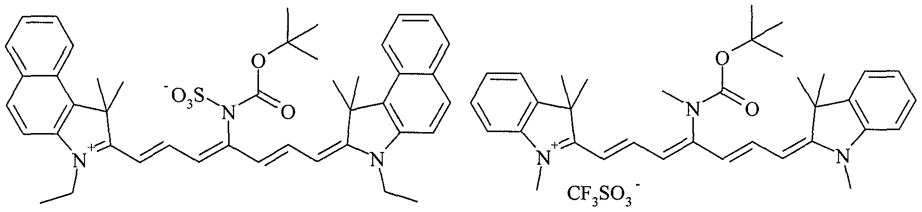


Claims


Priority Applications (7)
| Application Number | Priority Date | Filing Date | Title |
|---|---|---|---|
| US11/993,113 US8178282B2 (en) | 2005-06-21 | 2006-06-20 | Heat-sensitive imaging element |
| EP06777368.9A EP1910082B1 (en) | 2005-06-21 | 2006-06-20 | Infrared absorbing dye |
| ES06777368.9T ES2449230T3 (en) | 2005-06-21 | 2006-06-20 | Infrared ray absorbing dye |
| BRPI0612120-9A BRPI0612120A2 (en) | 2005-06-21 | 2006-06-20 | infrared absorber dye, heat sensitive imaging element, heat sensitive lithographic printing plate precursor and method for producing a lithographic printing plate |
| PL06777368T PL1910082T3 (en) | 2005-06-21 | 2006-06-20 | Infrared absorbing dye |
| JP2008517477A JP2008544053A (en) | 2005-06-21 | 2006-06-20 | Infrared absorbing dye |
| KR1020087001527A KR101362280B1 (en) | 2005-06-21 | 2006-06-20 | Infrared absorbing dye |
Applications Claiming Priority (4)
| Application Number | Priority Date | Filing Date | Title |
|---|---|---|---|
| EP05105440A EP1736312B1 (en) | 2005-06-21 | 2005-06-21 | Heat-sensitive imaging element |
| EP05105440.1 | 2005-06-21 | ||
| US69422605P | 2005-06-27 | 2005-06-27 | |
| US60/694,226 | 2005-06-27 |
Publications (2)
| Publication Number | Publication Date |
|---|---|
| WO2006136543A2 true WO2006136543A2 (en) | 2006-12-28 |
| WO2006136543A3 WO2006136543A3 (en) | 2008-04-10 |
Family
ID=35197918
Family Applications (2)
| Application Number | Title | Priority Date | Filing Date |
|---|---|---|---|
| PCT/EP2006/063303 WO2006136537A1 (en) | 2005-06-21 | 2006-06-19 | Heat-sensitive imaging element |
| PCT/EP2006/063327 WO2006136543A2 (en) | 2005-06-21 | 2006-06-20 | Infrared absorbing dye |
Family Applications Before (1)
| Application Number | Title | Priority Date | Filing Date |
|---|---|---|---|
| PCT/EP2006/063303 WO2006136537A1 (en) | 2005-06-21 | 2006-06-19 | Heat-sensitive imaging element |
Country Status (11)
| Country | Link |
|---|---|
| US (2) | US8148042B2 (en) |
| EP (2) | EP1736312B1 (en) |
| JP (2) | JP4884466B2 (en) |
| KR (1) | KR101362280B1 (en) |
| CN (2) | CN101203382B (en) |
| AT (1) | ATE391014T1 (en) |
| BR (2) | BRPI0611741B1 (en) |
| DE (1) | DE602005005804T2 (en) |
| ES (2) | ES2303991T3 (en) |
| PL (1) | PL1910082T3 (en) |
| WO (2) | WO2006136537A1 (en) |
Cited By (10)
| Publication number | Priority date | Publication date | Assignee | Title |
|---|---|---|---|---|
| EP2095948A1 (en) | 2008-02-28 | 2009-09-02 | Agfa Graphics N.V. | A method for making a lithographic printing plate |
| EP2113381A3 (en) * | 2008-04-29 | 2010-01-13 | Eastman Kodak Company | On-press developable elements and methods of use |
| EP2186637A1 (en) | 2008-10-23 | 2010-05-19 | Agfa Graphics N.V. | A lithographic printing plate |
| WO2011119114A1 (en) * | 2010-03-24 | 2011-09-29 | National University Of Singapore | Development of photostable near-ir cyanine dyes for in vivo imaging |
| US8148042B2 (en) | 2005-06-21 | 2012-04-03 | Agfa Graphics Nv | Heat-sensitive imaging element |
| US8685622B2 (en) | 2009-04-24 | 2014-04-01 | Agfa Graphics Nv | Method for preparing a lithographic printing plate |
| US8778590B2 (en) | 2008-12-18 | 2014-07-15 | Agfa Graphics Nv | Lithographic printing plate precursor |
| WO2015100441A1 (en) * | 2013-12-26 | 2015-07-02 | Raynergy Tek Incorporation | Conjugated polymers and devices incorporating the same |
| US11465403B2 (en) | 2018-03-22 | 2022-10-11 | Agfa Nv | Lithographic printing plate precursor |
| US11813838B2 (en) | 2018-05-14 | 2023-11-14 | Agfa Offset Bv | Lithographic printing plate precursor |
Families Citing this family (75)
| Publication number | Priority date | Publication date | Assignee | Title |
|---|---|---|---|---|
| PL2214056T3 (en) | 2005-11-18 | 2013-05-31 | Agfa Nv | Method of making a lithographic printing plate |
| DE602005012630D1 (en) | 2005-11-18 | 2009-03-19 | Agfa Graphics Nv | Process for producing a lithographic printing plate |
| EP1788435B1 (en) | 2005-11-21 | 2013-05-01 | Agfa Graphics N.V. | Method of making a lithographic printing plate |
| EP1788449A1 (en) | 2005-11-21 | 2007-05-23 | Agfa Graphics N.V. | Method for making a lithographic printing plate |
| ES2324542T3 (en) | 2005-11-21 | 2009-08-10 | Agfa Graphics N.V. | METHOD FOR MANUFACTURING A LITHOGRAPHIC PRINT IRON. |
| ATE439981T1 (en) * | 2005-11-24 | 2009-09-15 | Agfa Graphics Nv | METHOD FOR PRODUCING A LITHOGRAPHIC PRINTING PLATE |
| US8048607B2 (en) * | 2006-03-09 | 2011-11-01 | Fujifilm Corporation | Compound having polymethine-chain structure, image forming material, planographic printing plate precursor, and image forming method using the same, method of making planographic printing plate, and planographic printing method |
| EP1834764B1 (en) | 2006-03-17 | 2009-05-27 | Agfa Graphics N.V. | Negative working, heat-sensitive lithographic printing plate precursor |
| EP2234964B1 (en) | 2007-12-20 | 2016-05-04 | Agfa Graphics N.V. | Intermediate compounds for the preparation of meso-substituted cyanine, merocyanine and oxonole dyes. |
| US8240943B2 (en) | 2008-07-09 | 2012-08-14 | Eastman Kodak Company | On-press developable imageable elements |
| EP2328753B1 (en) * | 2008-09-16 | 2016-11-23 | Agfa Graphics NV | A lithographic printing plate precursor |
| US20100075258A1 (en) * | 2008-09-19 | 2010-03-25 | Munnelly Heidi M | On-press developable imageable elements |
| ATE555905T1 (en) * | 2009-10-27 | 2012-05-15 | Agfa Graphics Nv | NOVEL CYANINE DYES AND LITHOGRAPHIC PRINTING PLATE PRECURSORS WITH THE DYES |
| CN101747655B (en) * | 2009-12-24 | 2013-04-03 | 渤海大学 | Water-soluble cyanine dye containing azulene structure and synthetic method thereof |
| US8900798B2 (en) | 2010-10-18 | 2014-12-02 | Eastman Kodak Company | On-press developable lithographic printing plate precursors |
| EP2753981B1 (en) | 2011-09-08 | 2015-10-14 | AGFA Graphics NV | Method of making a lithographic printing plate |
| WO2013182328A1 (en) | 2012-06-05 | 2013-12-12 | Agfa Graphics Nv | A lithographic printing plate precursor |
| CN102841502B (en) * | 2012-09-21 | 2014-06-04 | 成都星科印刷器材有限公司 | Imaging liquid for thermosensitive CTP (cytidine triphosphate) plate |
| US8927197B2 (en) | 2012-11-16 | 2015-01-06 | Eastman Kodak Company | Negative-working lithographic printing plate precursors |
| EP3008517A1 (en) | 2013-06-14 | 2016-04-20 | Agfa Graphics N.V. | A lithographic printing plate precursor |
| DE112014003294T5 (en) * | 2013-07-18 | 2016-04-21 | Fujifilm Corporation | Lithographic printing plate precursor and method of making the same |
| JP6012871B2 (en) * | 2013-07-18 | 2016-10-25 | 富士フイルム株式会社 | Planographic printing plate precursor and plate making method |
| ES2601846T3 (en) * | 2013-11-07 | 2017-02-16 | Agfa Graphics Nv | Negative thermosensitive lithographic printing plate precursor |
| EP2883699B1 (en) | 2013-12-11 | 2017-05-03 | Agfa Graphics Nv | A lithographic printing plate precursor and monomer |
| EP2916171B1 (en) | 2014-03-03 | 2017-05-31 | Agfa Graphics Nv | A method for making a lithographic printing plate precursor |
| BR112017003349B1 (en) * | 2014-08-22 | 2022-12-20 | Fujifilm Corporation | COMPOUND, COLOR DEVELOPMENT COMPOSITION, LITHOGRAPHIC PRINTING PLATE PRECURSOR AND METHOD FOR PRODUCING PLATE FOR LITHOGRAPHIC PRINTING PLATE |
| US10286707B2 (en) | 2015-05-19 | 2019-05-14 | Agfa-Gevaert | Laser markable compositions, materials and documents |
| EP3121008B1 (en) | 2015-07-23 | 2018-06-13 | Agfa Nv | A lithographic printing plate precursor comprising graphite oxide |
| EP3418332B1 (en) | 2016-02-19 | 2021-08-25 | FUJIFILM Corporation | Chromogenic composition, planographic printing original plate, method for producing planographic printing plate, and chromogenic compound |
| EP3239184A1 (en) | 2016-04-25 | 2017-11-01 | Agfa Graphics NV | Thermoplastic polymer particles and a lithographic printing plate precursor |
| EP3508553B1 (en) | 2016-08-31 | 2022-01-12 | FUJIFILM Corporation | Color-assuming composition, lithographic printing plate precursor, method for forming lithographic printing plate, and compound |
| BR112019003997A2 (en) * | 2016-08-31 | 2019-05-28 | Fujifilm Corp | lithographic printing plate precursor and plate making method using the same |
| CN110382558A (en) | 2017-02-28 | 2019-10-25 | 富士胶片株式会社 | Solidification compound, original edition of lithographic printing plate, the production method of lithographic printing plate and compound |
| EP3392709A1 (en) | 2017-04-21 | 2018-10-24 | Agfa Nv | A lithographic printing plate precursor |
| EP3441223B1 (en) | 2017-08-07 | 2024-02-21 | Eco3 Bv | A lithographic printing plate precursor |
| EP3674796B1 (en) * | 2017-08-25 | 2023-11-22 | FUJIFILM Corporation | Negative-type planographic printing plate precursor and method for producing planographic printing plate |
| JP7027099B2 (en) * | 2017-09-29 | 2022-03-01 | キヤノン株式会社 | Manufacturing method of imprint device and goods |
| EP3474073B1 (en) | 2017-10-17 | 2022-12-07 | Agfa Offset Bv | A method for making a printing plate |
| EP3587113B1 (en) | 2018-06-21 | 2023-01-04 | Agfa Offset Bv | A lithographic printing plate precursor |
| EP3587112B1 (en) | 2018-06-21 | 2024-04-03 | Eco3 Bv | A lithographic printing plate precursor |
| WO2020090996A1 (en) | 2018-10-31 | 2020-05-07 | 富士フイルム株式会社 | Lithographic printing plate original plate, method for producing lithographic printing plate and lithographic printing method |
| WO2020090995A1 (en) | 2018-10-31 | 2020-05-07 | 富士フイルム株式会社 | Lithographic printing plate original plate, method for producing lithographic printing plate and lithographic printing method |
| EP3650938A1 (en) | 2018-11-09 | 2020-05-13 | Agfa Nv | A lithographic printing plate precursor |
| EP3904100A4 (en) | 2019-01-31 | 2022-06-08 | FUJIFILM Corporation | Lithographic printing plate precursor, method for manufacturing lithographic printing plate, and lithographic printing method |
| EP3900942A4 (en) | 2019-01-31 | 2022-03-09 | FUJIFILM Corporation | Lithographic printing plate precursor, method for manufacturing lithographic printing plate, and lithographic printing method |
| EP3715140A1 (en) | 2019-03-29 | 2020-09-30 | Agfa Nv | A method of printing |
| EP3991983A4 (en) | 2019-06-28 | 2022-08-10 | FUJIFILM Corporation | Original plate for on-press development type lithographic printing plate, method for fabricating lithographic printing plate, and lithographic printing method |
| CN114051459A (en) | 2019-06-28 | 2022-02-15 | 富士胶片株式会社 | Lithographic printing plate precursor, method for producing lithographic printing plate, and lithographic printing method |
| EP3991986A4 (en) | 2019-06-28 | 2022-09-28 | FUJIFILM Corporation | Original plate for on-press development type lithographic printing plate, method for fabricating lithographic printing plate, and lithographic printing method |
| EP3991987A4 (en) | 2019-06-28 | 2022-09-14 | FUJIFILM Corporation | On-press-development-type lithographic printing plate precursor, lithographic printing plate production method, and lithographic printing method |
| JP7282885B2 (en) | 2019-06-28 | 2023-05-29 | 富士フイルム株式会社 | Lithographic printing plate precursor, method for preparing lithographic printing plate, and method for lithographic printing |
| CN114096914A (en) | 2019-06-28 | 2022-02-25 | 富士胶片株式会社 | On-press developable lithographic printing plate precursor, method for producing lithographic printing plate, and lithographic printing method |
| EP3991990A4 (en) | 2019-06-28 | 2022-08-17 | FUJIFILM Corporation | Original plate for on-press development type lithographic printing plate, method for fabricating lithographic printing plate, and lithographic printing method |
| EP3815900A1 (en) | 2019-10-31 | 2021-05-05 | Agfa Nv | A lithographic printing plate precursor and method for making hydrophobic resin particles |
| JP7394874B2 (en) | 2019-12-27 | 2023-12-08 | 富士フイルム株式会社 | Lithographic printing method |
| EP3875271A1 (en) | 2020-03-04 | 2021-09-08 | Agfa Nv | A lithographic printing plate precursor |
| EP3892469B1 (en) | 2020-04-10 | 2023-11-08 | Eco3 Bv | Lithographic printing plate precursor |
| CN115666959A (en) | 2020-05-29 | 2023-01-31 | 富士胶片株式会社 | On-press developable lithographic printing plate precursor, method for producing lithographic printing plate, and lithographic printing method |
| WO2021241519A1 (en) | 2020-05-29 | 2021-12-02 | 富士フイルム株式会社 | On-press-development-type lithographic printing plate precursor, lithographic printing plate production method, and lithographic printing method |
| WO2021241688A1 (en) | 2020-05-29 | 2021-12-02 | 富士フイルム株式会社 | Original plate for on-machine development type lithographic printing plate, lithographic printing plate manufacturing method, and lithographic printing method |
| EP3922462B1 (en) | 2020-06-08 | 2023-03-01 | Agfa Offset Bv | Lithographic photopolymer printing plate precursor with improved daylight stability |
| US20230311474A1 (en) | 2020-06-24 | 2023-10-05 | Agfa Offset Bv | A Lithographic Printing Plate Precursor |
| EP3928983B1 (en) | 2020-06-24 | 2023-09-27 | Eco3 Bv | A lithographic printing plate precursor |
| US20230266667A1 (en) | 2020-06-24 | 2023-08-24 | Agfa Offset Bv | A Lithographic Printing Plate Precursor |
| WO2022019217A1 (en) | 2020-07-21 | 2022-01-27 | 富士フイルム株式会社 | On-machine-developing-type planographic printing plate original plate, method for manufacturing planographic printing plate, and planographic printing method |
| EP4263224A1 (en) | 2020-12-16 | 2023-10-25 | Eco3 Bv | Lithographic printing press make-ready method |
| EP4035897A1 (en) | 2021-01-28 | 2022-08-03 | Agfa Offset Bv | A lithographic printing plate precursor |
| WO2022212032A1 (en) | 2021-04-01 | 2022-10-06 | Eastman Kodak Company | Lithographic printing plate precursor and method of use |
| EP4129682A1 (en) | 2021-08-05 | 2023-02-08 | Agfa Offset Bv | A lithographic printing plate precursor |
| WO2023032681A1 (en) | 2021-08-31 | 2023-03-09 | 富士フイルム株式会社 | Multilayer body |
| WO2023032682A1 (en) | 2021-08-31 | 2023-03-09 | 富士フイルム株式会社 | On-press-developing lithographic printing original plate, method for producing lithographic printing plate, and lithographic printing method |
| EP4223534A1 (en) | 2022-02-07 | 2023-08-09 | Agfa Offset Bv | A lithographic printing plate precursor |
| US20230314935A1 (en) | 2022-03-03 | 2023-10-05 | Eastman Kodak Company | Lithographic printing plate precursor and method of use |
| EP4245542A1 (en) | 2022-03-18 | 2023-09-20 | FUJIFILM Corporation | Lithographic printing plate precursor, method of preparing lithographic printing plate, and lithographic printing method |
| US20240069439A1 (en) | 2022-08-12 | 2024-02-29 | Eastman Kodak Company | Lithographic printing plate precursor and method of use |
Citations (25)
| Publication number | Priority date | Publication date | Assignee | Title |
|---|---|---|---|---|
| US3042515A (en) | 1959-01-16 | 1962-07-03 | Horizons Inc | Print-out compositions for photographic purposes and process of using same |
| US3359109A (en) | 1964-04-29 | 1967-12-19 | Du Pont | Leuco dye-n, n. o-triacylhydroxylamine light-sensitive dye former compositions |
| US4139390A (en) | 1977-02-10 | 1979-02-13 | Eastman Kodak Company | Presensitized printing plate having a print-out image |
| US4232106A (en) | 1977-11-28 | 1980-11-04 | Fuji Photo Film Co., Ltd. | Photosensitive compositions containing 2-halomethyl-5-vinyl-1,3,4-oxadiazoles as free radical progenitors |
| US4258123A (en) | 1978-08-29 | 1981-03-24 | Fuji Photo Film Co., Ltd. | Photosensitive resin composition |
| US4425424A (en) | 1982-04-08 | 1984-01-10 | Eastman Kodak Company | Dye-forming compositions |
| DD213530A1 (en) | 1983-02-01 | 1984-09-12 | Leipzig Tech Hochschule | METHOD OF FORMING MANUFACTURE WITH THE HELP OF A LASER |
| US4598036A (en) | 1983-09-08 | 1986-07-01 | Fuji Photo Film Co., Ltd. | Print-out compositions |
| EP0419095A2 (en) | 1989-09-18 | 1991-03-27 | Du Pont (UK) Limited | Radiation sensitive compositions |
| EP0434968A2 (en) | 1989-11-29 | 1991-07-03 | BASF Aktiengesellschaft | Light-sensitive preparation and process for the fabrication of photoresists and printing plates |
| US5030548A (en) | 1988-08-11 | 1991-07-09 | Fuji Photo Film Co., Ltd. | Photo-polymerizable composition |
| US5141842A (en) | 1991-03-27 | 1992-08-25 | Eastman Kodak Company | Radiation-sensitive compositions comprising a photocrosslinkable polymer, a leuco dye, a photooxidant and a heteroaromatic amine n-oxide |
| US5141839A (en) | 1991-03-27 | 1992-08-25 | Eastman Kodak Company | Lithographic printing plates having a radiation-sensitive layer comprising a photocrosslinkable polymer, a leuco dye, a photooxidant and a heteroaromatic amine n-oxide |
| WO1996035143A1 (en) | 1995-05-02 | 1996-11-07 | Minnesota Mining And Manufacturing Company | Acid bleachable dye containing lithographic printing plate composition |
| EP0897134A2 (en) | 1997-08-13 | 1999-02-17 | Mitsubishi Chemical Corporation | Positive photosensitive composition, photosensitive lithographic printing plate and method for forming a positive image |
| EP0925916A1 (en) | 1997-12-09 | 1999-06-30 | Agfa-Gevaert N.V. | A heat sensitive non-ablatable wasteless imaging element for providing a lithographic printing plate with a difference in dye density between the image and non image areas |
| JP2001246848A (en) | 2000-03-03 | 2001-09-11 | Fuji Photo Film Co Ltd | Nonsilver image recording material |
| EP1300241A2 (en) | 2001-10-03 | 2003-04-09 | Fuji Photo Film Co., Ltd. | Lithographic printing plate precursor |
| US20030068575A1 (en) | 2001-09-10 | 2003-04-10 | Fuji Photo Film Co., Ltd. | Lithographic printing plate precursor |
| EP1428676A2 (en) | 2002-12-12 | 2004-06-16 | Konica Minolta Holdings, Inc. | Printing plate material |
| JP2004301915A (en) | 2003-03-28 | 2004-10-28 | Fuji Photo Film Co Ltd | Polymerizable composition and lithographic printing original plate using the same |
| EP1502736A2 (en) | 2003-07-30 | 2005-02-02 | Fuji Photo Film Co., Ltd. | Lithographic printing process |
| EP1508440A2 (en) | 2003-08-22 | 2005-02-23 | Fuji Photo Film Co., Ltd. | Lithographic printing process |
| JP2005062482A (en) | 2003-08-12 | 2005-03-10 | Fuji Photo Film Co Ltd | Polymerizable composition and recording material using the same |
| JP2005122038A (en) | 2003-10-20 | 2005-05-12 | Fuji Photo Film Co Ltd | Polymerized composition and image recording material using it |
Family Cites Families (20)
| Publication number | Priority date | Publication date | Assignee | Title |
|---|---|---|---|---|
| JPS62193885A (en) * | 1986-02-20 | 1987-08-26 | Olympus Optical Co Ltd | Optical information-recording medium |
| JPH087399B2 (en) * | 1988-04-18 | 1996-01-29 | 富士写真フイルム株式会社 | Infrared photosensitive silver halide photosensitive material |
| CA1337923C (en) * | 1988-07-07 | 1996-01-16 | Richard Lee Parton | Infrared filter dye for photographic element |
| DE4331162A1 (en) * | 1993-09-14 | 1995-03-16 | Bayer Ag | Process for the preparation of cyanine dyes |
| DE69526617T2 (en) * | 1994-09-22 | 2002-08-29 | Fuji Photo Film Co Ltd | Infrared absorbing dye Silver halide photographic material |
| JP3616173B2 (en) * | 1994-09-22 | 2005-02-02 | 富士写真フイルム株式会社 | Silver halide photographic light-sensitive material and image forming method |
| JPH10207010A (en) * | 1997-01-20 | 1998-08-07 | Fuji Photo Film Co Ltd | Silver halide color photographic sensitive material |
| US5972838A (en) * | 1998-06-24 | 1999-10-26 | Eastman Kodak Company | Infrared-absorbing cyanine colorants for laser-colorant transfer |
| JP4139539B2 (en) * | 2000-01-21 | 2008-08-27 | 富士フイルム株式会社 | Photopolymerizable image recording material and planographic printing plate precursor |
| JP4335416B2 (en) * | 2000-06-06 | 2009-09-30 | 富士フイルム株式会社 | Image forming material and infrared absorbing dye |
| US6482571B1 (en) * | 2000-09-06 | 2002-11-19 | Gary Ganghui Teng | On-press development of thermosensitive lithographic plates |
| JP2004117547A (en) * | 2002-09-24 | 2004-04-15 | Fuji Photo Film Co Ltd | Lithographic printing master plate |
| JP2004181802A (en) * | 2002-12-04 | 2004-07-02 | Konica Minolta Holdings Inc | Planographic printing plate material and printing method therefor |
| US6902861B2 (en) * | 2003-03-10 | 2005-06-07 | Kodak Polychrome Graphics, Llc | Infrared absorbing compounds and their use in photoimageable elements |
| US7368215B2 (en) * | 2003-05-12 | 2008-05-06 | Eastman Kodak Company | On-press developable IR sensitive printing plates containing an onium salt initiator system |
| JP4299639B2 (en) * | 2003-07-29 | 2009-07-22 | 富士フイルム株式会社 | Polymerizable composition and image recording material using the same |
| US7741379B2 (en) * | 2005-03-01 | 2010-06-22 | Hewlett-Packard Development Company, L.P. | System and a method for a UV curable ink having infrared sensitivity |
| JP2006259380A (en) * | 2005-03-17 | 2006-09-28 | Fuji Photo Film Co Ltd | Polymerizable composition and lithographic printing original plate using the same |
| ES2303991T3 (en) | 2005-06-21 | 2008-09-01 | Agfa Graphics N.V. | HEAT SENSITIVE IMAGE FORMATION ELEMENT. |
| US8313885B2 (en) * | 2005-11-10 | 2012-11-20 | Agfa Graphics Nv | Lithographic printing plate precursor comprising bi-functional compounds |
-
2005
- 2005-06-21 ES ES05105440T patent/ES2303991T3/en active Active
- 2005-06-21 AT AT05105440T patent/ATE391014T1/en active
- 2005-06-21 EP EP05105440A patent/EP1736312B1/en active Active
- 2005-06-21 DE DE602005005804T patent/DE602005005804T2/en active Active
-
2006
- 2006-06-19 WO PCT/EP2006/063303 patent/WO2006136537A1/en active Application Filing
- 2006-06-19 BR BRPI0611741A patent/BRPI0611741B1/en not_active IP Right Cessation
- 2006-06-19 JP JP2008517474A patent/JP4884466B2/en active Active
- 2006-06-19 US US11/993,105 patent/US8148042B2/en active Active
- 2006-06-19 CN CN2006800221370A patent/CN101203382B/en active Active
- 2006-06-20 ES ES06777368.9T patent/ES2449230T3/en active Active
- 2006-06-20 KR KR1020087001527A patent/KR101362280B1/en active IP Right Grant
- 2006-06-20 BR BRPI0612120-9A patent/BRPI0612120A2/en not_active Application Discontinuation
- 2006-06-20 US US11/993,113 patent/US8178282B2/en active Active
- 2006-06-20 PL PL06777368T patent/PL1910082T3/en unknown
- 2006-06-20 CN CNA2006800224646A patent/CN101237991A/en active Pending
- 2006-06-20 WO PCT/EP2006/063327 patent/WO2006136543A2/en active Application Filing
- 2006-06-20 JP JP2008517477A patent/JP2008544053A/en active Pending
- 2006-06-20 EP EP06777368.9A patent/EP1910082B1/en active Active
Patent Citations (25)
| Publication number | Priority date | Publication date | Assignee | Title |
|---|---|---|---|---|
| US3042515A (en) | 1959-01-16 | 1962-07-03 | Horizons Inc | Print-out compositions for photographic purposes and process of using same |
| US3359109A (en) | 1964-04-29 | 1967-12-19 | Du Pont | Leuco dye-n, n. o-triacylhydroxylamine light-sensitive dye former compositions |
| US4139390A (en) | 1977-02-10 | 1979-02-13 | Eastman Kodak Company | Presensitized printing plate having a print-out image |
| US4232106A (en) | 1977-11-28 | 1980-11-04 | Fuji Photo Film Co., Ltd. | Photosensitive compositions containing 2-halomethyl-5-vinyl-1,3,4-oxadiazoles as free radical progenitors |
| US4258123A (en) | 1978-08-29 | 1981-03-24 | Fuji Photo Film Co., Ltd. | Photosensitive resin composition |
| US4425424A (en) | 1982-04-08 | 1984-01-10 | Eastman Kodak Company | Dye-forming compositions |
| DD213530A1 (en) | 1983-02-01 | 1984-09-12 | Leipzig Tech Hochschule | METHOD OF FORMING MANUFACTURE WITH THE HELP OF A LASER |
| US4598036A (en) | 1983-09-08 | 1986-07-01 | Fuji Photo Film Co., Ltd. | Print-out compositions |
| US5030548A (en) | 1988-08-11 | 1991-07-09 | Fuji Photo Film Co., Ltd. | Photo-polymerizable composition |
| EP0419095A2 (en) | 1989-09-18 | 1991-03-27 | Du Pont (UK) Limited | Radiation sensitive compositions |
| EP0434968A2 (en) | 1989-11-29 | 1991-07-03 | BASF Aktiengesellschaft | Light-sensitive preparation and process for the fabrication of photoresists and printing plates |
| US5141839A (en) | 1991-03-27 | 1992-08-25 | Eastman Kodak Company | Lithographic printing plates having a radiation-sensitive layer comprising a photocrosslinkable polymer, a leuco dye, a photooxidant and a heteroaromatic amine n-oxide |
| US5141842A (en) | 1991-03-27 | 1992-08-25 | Eastman Kodak Company | Radiation-sensitive compositions comprising a photocrosslinkable polymer, a leuco dye, a photooxidant and a heteroaromatic amine n-oxide |
| WO1996035143A1 (en) | 1995-05-02 | 1996-11-07 | Minnesota Mining And Manufacturing Company | Acid bleachable dye containing lithographic printing plate composition |
| EP0897134A2 (en) | 1997-08-13 | 1999-02-17 | Mitsubishi Chemical Corporation | Positive photosensitive composition, photosensitive lithographic printing plate and method for forming a positive image |
| EP0925916A1 (en) | 1997-12-09 | 1999-06-30 | Agfa-Gevaert N.V. | A heat sensitive non-ablatable wasteless imaging element for providing a lithographic printing plate with a difference in dye density between the image and non image areas |
| JP2001246848A (en) | 2000-03-03 | 2001-09-11 | Fuji Photo Film Co Ltd | Nonsilver image recording material |
| US20030068575A1 (en) | 2001-09-10 | 2003-04-10 | Fuji Photo Film Co., Ltd. | Lithographic printing plate precursor |
| EP1300241A2 (en) | 2001-10-03 | 2003-04-09 | Fuji Photo Film Co., Ltd. | Lithographic printing plate precursor |
| EP1428676A2 (en) | 2002-12-12 | 2004-06-16 | Konica Minolta Holdings, Inc. | Printing plate material |
| JP2004301915A (en) | 2003-03-28 | 2004-10-28 | Fuji Photo Film Co Ltd | Polymerizable composition and lithographic printing original plate using the same |
| EP1502736A2 (en) | 2003-07-30 | 2005-02-02 | Fuji Photo Film Co., Ltd. | Lithographic printing process |
| JP2005062482A (en) | 2003-08-12 | 2005-03-10 | Fuji Photo Film Co Ltd | Polymerizable composition and recording material using the same |
| EP1508440A2 (en) | 2003-08-22 | 2005-02-23 | Fuji Photo Film Co., Ltd. | Lithographic printing process |
| JP2005122038A (en) | 2003-10-20 | 2005-05-12 | Fuji Photo Film Co Ltd | Polymerized composition and image recording material using it |
Cited By (11)
| Publication number | Priority date | Publication date | Assignee | Title |
|---|---|---|---|---|
| US8148042B2 (en) | 2005-06-21 | 2012-04-03 | Agfa Graphics Nv | Heat-sensitive imaging element |
| EP2095948A1 (en) | 2008-02-28 | 2009-09-02 | Agfa Graphics N.V. | A method for making a lithographic printing plate |
| EP2113381A3 (en) * | 2008-04-29 | 2010-01-13 | Eastman Kodak Company | On-press developable elements and methods of use |
| EP2186637A1 (en) | 2008-10-23 | 2010-05-19 | Agfa Graphics N.V. | A lithographic printing plate |
| US8778590B2 (en) | 2008-12-18 | 2014-07-15 | Agfa Graphics Nv | Lithographic printing plate precursor |
| US8685622B2 (en) | 2009-04-24 | 2014-04-01 | Agfa Graphics Nv | Method for preparing a lithographic printing plate |
| WO2011119114A1 (en) * | 2010-03-24 | 2011-09-29 | National University Of Singapore | Development of photostable near-ir cyanine dyes for in vivo imaging |
| US9201014B2 (en) | 2010-03-24 | 2015-12-01 | National University Of Singapore | Development of photostable near-IR cyanine dyes for in vivo imaging |
| WO2015100441A1 (en) * | 2013-12-26 | 2015-07-02 | Raynergy Tek Incorporation | Conjugated polymers and devices incorporating the same |
| US11465403B2 (en) | 2018-03-22 | 2022-10-11 | Agfa Nv | Lithographic printing plate precursor |
| US11813838B2 (en) | 2018-05-14 | 2023-11-14 | Agfa Offset Bv | Lithographic printing plate precursor |
Also Published As
| Publication number | Publication date |
|---|---|
| BRPI0611741A2 (en) | 2010-09-28 |
| JP4884466B2 (en) | 2012-02-29 |
| DE602005005804T2 (en) | 2009-04-09 |
| BRPI0611741B1 (en) | 2018-10-23 |
| EP1736312A1 (en) | 2006-12-27 |
| ATE391014T1 (en) | 2008-04-15 |
| US20100040976A1 (en) | 2010-02-18 |
| CN101203382B (en) | 2010-04-21 |
| EP1910082B1 (en) | 2014-01-22 |
| US20100221662A1 (en) | 2010-09-02 |
| ES2449230T3 (en) | 2014-03-18 |
| JP2008544053A (en) | 2008-12-04 |
| KR20080014152A (en) | 2008-02-13 |
| DE602005005804D1 (en) | 2008-05-15 |
| WO2006136537A1 (en) | 2006-12-28 |
| BRPI0612120A2 (en) | 2010-10-19 |
| PL1910082T3 (en) | 2014-06-30 |
| BRPI0611741A8 (en) | 2018-05-02 |
| US8178282B2 (en) | 2012-05-15 |
| ES2303991T3 (en) | 2008-09-01 |
| EP1736312B1 (en) | 2008-04-02 |
| CN101237991A (en) | 2008-08-06 |
| EP1910082A2 (en) | 2008-04-16 |
| US8148042B2 (en) | 2012-04-03 |
| JP2008544322A (en) | 2008-12-04 |
| WO2006136543A3 (en) | 2008-04-10 |
| CN101203382A (en) | 2008-06-18 |
| KR101362280B1 (en) | 2014-02-13 |
Similar Documents
| Publication | Publication Date | Title |
|---|---|---|
| EP1910082B1 (en) | Infrared absorbing dye | |
| EP1554347B1 (en) | Polymer for heat-sensitive lithographic printing plate precursor | |
| WO2004071767A1 (en) | Heat-sensitive lithographic printing plate precursor. | |
| EP3239184A1 (en) | Thermoplastic polymer particles and a lithographic printing plate precursor | |
| EP2489512B1 (en) | A lithographic printing plate precursor | |
| US7348126B2 (en) | Negative working, heat-sensitive lithographic printing plate precursor | |
| EP1738900B1 (en) | Heat-sensitive lithographic printing plate precursor | |
| US7087359B2 (en) | Heat-sensitive lithographic printing plate precursor | |
| EP1297950B1 (en) | Heat-sensitive lithographic printing plate precursor | |
| US20040048195A1 (en) | Heat-sensitive lithographic printing plate precursor | |
| EP1473156B1 (en) | Heat-sensitive lithographic printing plate precursor | |
| EP1604818B1 (en) | Negative working, heat-sensitive lithographic printing plate precursor | |
| EP1396338B1 (en) | Heat-sensitive lithographic printing plate precursor | |
| EP1543959B1 (en) | Heat-sensitive lithographic printing plate precursor. | |
| WO2009030279A1 (en) | A heat-sensitive lithographic printing plate precursor | |
| EP1440797B1 (en) | Heat-sensitive lithographic printing plate precursor | |
| JP2003162053A (en) | Heat sensitive lithographic printing plate precursor | |
| JP2005181963A (en) | Heat-sensitive lithographic printing plate precursor |
Legal Events
| Date | Code | Title | Description |
|---|---|---|---|
| WWE | Wipo information: entry into national phase |
Ref document number: 2006777368 Country of ref document: EP |
|
| WWE | Wipo information: entry into national phase |
Ref document number: 11993113 Country of ref document: US |
|
| WWE | Wipo information: entry into national phase |
Ref document number: 5879/CHENP/2007 Country of ref document: IN |
|
| WWE | Wipo information: entry into national phase |
Ref document number: 2008517477 Country of ref document: JP Ref document number: 200680022464.6 Country of ref document: CN |
|
| NENP | Non-entry into the national phase |
Ref country code: DE |
|
| WWW | Wipo information: withdrawn in national office |
Ref document number: DE |
|
| WWE | Wipo information: entry into national phase |
Ref document number: 1020087001527 Country of ref document: KR |
|
| WWP | Wipo information: published in national office |
Ref document number: 2006777368 Country of ref document: EP |
|
| ENP | Entry into the national phase |
Ref document number: PI0612120 Country of ref document: BR Kind code of ref document: A2 |