WO2006135358A1 - Method, apparatus and system for alternate image/video insertion - Google Patents
Method, apparatus and system for alternate image/video insertion Download PDFInfo
- Publication number
- WO2006135358A1 WO2006135358A1 PCT/US2005/020229 US2005020229W WO2006135358A1 WO 2006135358 A1 WO2006135358 A1 WO 2006135358A1 US 2005020229 W US2005020229 W US 2005020229W WO 2006135358 A1 WO2006135358 A1 WO 2006135358A1
- Authority
- WO
- WIPO (PCT)
- Prior art keywords
- video content
- alternate image
- video
- image
- alternate
- Prior art date
Links
Classifications
-
- H—ELECTRICITY
- H04—ELECTRIC COMMUNICATION TECHNIQUE
- H04N—PICTORIAL COMMUNICATION, e.g. TELEVISION
- H04N5/00—Details of television systems
- H04N5/222—Studio circuitry; Studio devices; Studio equipment
- H04N5/262—Studio circuits, e.g. for mixing, switching-over, change of character of image, other special effects ; Cameras specially adapted for the electronic generation of special effects
- H04N5/272—Means for inserting a foreground image in a background image, i.e. inlay, outlay
-
- H—ELECTRICITY
- H04—ELECTRIC COMMUNICATION TECHNIQUE
- H04N—PICTORIAL COMMUNICATION, e.g. TELEVISION
- H04N5/00—Details of television systems
- H04N5/222—Studio circuitry; Studio devices; Studio equipment
- H04N5/262—Studio circuits, e.g. for mixing, switching-over, change of character of image, other special effects ; Cameras specially adapted for the electronic generation of special effects
- H04N5/265—Mixing
Definitions
- This invention relates to video systems, and more particularly, to a method, apparatus and system for inserting alternate image/video into an existing video.
- Means for merging two or more video signals to provide a single composite video signal is known in the art.
- An example of such video merging is presentation of weather- forecasts on television, where a weather-forecaster in the foreground is superimposed on a weather-map in the background.
- Such prior-art means normally use a color-key merging technology in which the required foreground scene is recorded using a colored background (usually blue or green). The required background scene is also recorded.
- the color-key video merging technique uses the color of each point in the foreground scene to automatically "hard” switch (i.e., binary switch) between the foreground and background video signal.
- the color-key video merging technique uses the color of each point in the foreground scene to automatically switch between the foreground and background video signal. In particular, if a blue pixel is detected in the foreground scene (assuming blue is the color key), then a video switch will direct the video signal from the background scene to the output scene at that point.
- the video switch will direct the video from the foreground scene to the output scene at that point. After all points have been processed in this way, the result is an output scene which is a combination of the input foreground and background scenes.
- the effects of switching may be hidden and more natural merging may be achieved. For instance, shadows of foreground subjects may be made to appear in the background.
- color-key merging technique is simple, and cheap hardware for this method has been available for some time.
- color-key insertion can be performed on both recorded and live video. It is used widely in live television for such purposes as superimposing sports results or images of reporters on top of background scenes, and in the fi lm industry lor such purposes ; ⁇ s superimposing foreground objects (like space-ships) onto background scenes (like space-scenes).
- the present invention addresses the deficiencies of the prior art by providing a method, apparatus and system for alternate image/video insertion.
- a method for alternate image insertion includes storing metadata regarding a capture of a first video content, the first video content having identified areas that are able to be replaced with alternate image/video content, capturing an alternate image/video using the stored metadata associated with the first video content, and scaling the captured alternate image/video such that the alternate image/video is able to be integrated into a predetermined area of the first video content.
- a system for alternate image insertion includes at least one imaging device for capturing images/video, and a processing and control unit including a processor and a memory, where the processing and control unit is adapted to store metadata regarding a capture of a first video content, the first video content having identified areas that are able to be replaced with alternate image/video content, to post process the first video content to create new metadata describing a time-stamped matte for areas in the first video content capable of being replaced, to capture an alternate image/video using the stored metadata associated with the capture of the first video content, and to scale the captured alternate image/video such that the alternate image/video is able to be integrated into a predetermined area of the first video content.
- FIG. 1 depicts a high level block diagram of an Alternate Image/Video Insertion Process (AIVIP) system in accordance with an embodiment of the present invention
- FIG. 2 depicts a high level block diagram of an embodiment of a processing and control unit suitable for use in the AIVIP system 100 of FIG. I ;
- FIG. 3 depicts a high level functional block diagram of ihe processes of the AIVlP system of FlG. 1 ,
- FIG. 4 depicts a high level block diagram of an AIVlP system of the present invention, where the positioning of the second object relative to the second camera is controlled by the processing and control unit;
- FIG. 5 depicts a high level block diagram of an AIVIP system of the present invention where the positioning of the second camera relative to the second object is controlled by the processing and control unit;
- FIG. 6 depicts a flow diagram of a method of alternate video insertion in accordance with an embodiment of the present invention.
- the present invention advantageously provides a method, apparatus and system for image composition whereby alternate image or video content may be selectively inserted into an original video in real time.
- the present invention will be described primarily within the context of an Alternate Image/Video Insertion Process system comprising cameras for performing imaging, it will be appreciated by those skilled in the relevant art, informed by the teachings of the present invention that the concepts of the present invention may be applied to systems implementing substantially any imaging devices.
- the aspects of the invention are and will be described with respect to merging the images of objects, it should be understood that the term objects as used herein should be interpreted to represent videos, images and the like.
- teachings of the present invention herein are directed, at least ill part, to the insertion of an imagc(s), vidco(s) and the like, such as computer generated animation, into an existing imagc(s), video(s) and the like, such as other computer generated animation.
- FIG. 1 depicts a high level block diagram of an Alternate Image/Video Insertion Process (AlVIP) system in accordance with an embodiment of lhc present invention.
- the AlVlP system 100 of FlG. 1 illustratively comprises a source imaging device (illustratively a first camera) 102, a secondary imaging device (illustratively a second camera) 104, and a processing and control unit 1 10.
- FIG. 1 further illustrates a source object 106 to be imaged and a secondary object 108 to be imaged and integrated into the first imaged object.
- the source imaging device 102 and the ⁇ secoi ⁇ daryln ⁇ aging device 104 may comprise any devices capable of imaging an object, such as a camera and the like.
- an AIVlP system in accordance with the present invention may comprise a single imaging device for imaging both a source object and a secondary object.
- FIG. 2 depicts a high level block diagram of an embodiment of a processing and control unit 1 10 suitable for use in the AIVlP system 100 of FlG. 1.
- the processing and control unit 1 10 of FIG. 2 comprises a processor 210 as well as a memory 220 for storing control programs, stored images and the like.
- the processor 210 cooperates with conventional support circuitry 230 such as power supplies, clock circuits, cache memory and the like as well as circuits that assist in executing the software routines stored in the memory 220.
- conventional support circuitry 230 such as power supplies, clock circuits, cache memory and the like as well as circuits that assist in executing the software routines stored in the memory 220.
- it is contemplated that some of the process steps discussed herein as software processes may be implemented within hardware, for example, as circuitry that cooperates with the processor 210 to perform various steps.
- the processing and control unit 110 also contains input-output circuitry 240 that forms an interface between the various functional elements communicating with the processing and control unit 110.
- the control unit 110 communicates with the source imaging device 102 via a first path S l and communicates with a secondary imaging device 104 via a second path S2.
- processing and control unit 110 of FIG. 2 is depicted as a general purpose computer that is programmed to perform various control functions in accordance with the present invention, the invention can be implemented in hardware, for example, as an application specified integrated circuit (ASIC). As such, the process steps described herein arc intended Io be broadly interpreted as being equivalently performed by software, hardware, or a combination thereof.
- ASIC application specified integrated circuit
- alternate images or video content may be selectively integrated into an original video in real lime. That is, in an AIVlP system of the present invention, such as the AlVIP system 100 of FIG. 1 , sufficient metadata is created and stored at the time of the creation of an original video content to both describe objects/areas in the original video that arc available for integration of alternate images/video and to provide a means of controlling the alternate video capture and processing to fit the alternate image/video into the areas in the original video defined as a vailable forintcgrati on of alternate image/video.
- FIG. 3 depicts a high level functional block diagram of the processes of the AlVIP system 100 of FIG. I . More specifically, FJG. 3 illustratively comprises a Content Creation process block 310, a Post Processing process block 330, an Alternate Video/Image Capture process block 350, and a Final Image Composition process block 370.
- contours may be recorded near the time (or at the same time) as the general image capture. Further, physical information can also be collected about objects which might occlude the object of interest. All of this information provides pertinent information to the post production process to allow segmentation/separation of the objects of interest from the surrounding background.
- the original content is post processed to create new metadata to describe the time-stamped matte for each object of interest. That is for example, the location of the predefined areas in the original video content that are able to be replaced with alternate image content are identified and their position in the original video content recorded by, for example, the time they appear in the original video content.
- new metadata is created for the lime-stamped information as described above.
- cct, camera, and matte metadata arc used to control the positioning of the second camera 104 relative to the second object 108. Using specific information about the object's physical characteristics and its distance/relative position from the camera, it is possible to determine the boundary of the object of interest from other elements in the video capture. With the object boundary, it is now possible to create a matte which can be used to recover the object independent from the background or to remove the object for downstream insertion.
- an image of the second object 108 is then captured using the second camera 104 and the information for the positioning of the second objcct " 108 ⁇ and thc ⁇ sccond camera 104 ' determined in the Post Processing process 330.
- the relative position of the second camera 104 to the second object 108, the environmental factors (e.g., the lighting, the temperature, etc.), and the like are controlled such that the conditions for the second camera 104 to take an image of the second object 108 arc substantially the same as the conditions for when the first camera 102 took the image of the first object 106.
- the image of the second object 108 may be captured using a color-key merging technology in which the second object 108, a portion of which or which is to be totally combined with a first object 104, is recorded using a colored background (usually blue or green).
- the color-key video merging technique uses the color of each point in the foreground scene to automatically "hard" switch (i.e., binary switch) between the inserted object and the original object.
- the color-key video merging technique uses the color of each point in object to be inserted to automatically merge the object to be inserted with the source object.
- the image of the second object 108 may be captured using a camera or technique that in addition to RGB information, communicates an additional parameter indicating distance. That is in such an embodiment of the present invention, the camera or technique is capable of generating 3 dimensional images of the field of view (FOV) when looking from a single vantage point.
- the unique camera is capable of doing so at video rate and is compatible with all existing standards and formats.
- the concept of operation is based on generating a "light wall" having a proper width moving along the FOV.
- the light wall can be generated, for example, as a square laser pulse of short duration having a field of illumination (FOI) equal to the FOV.
- FOI field of illumination
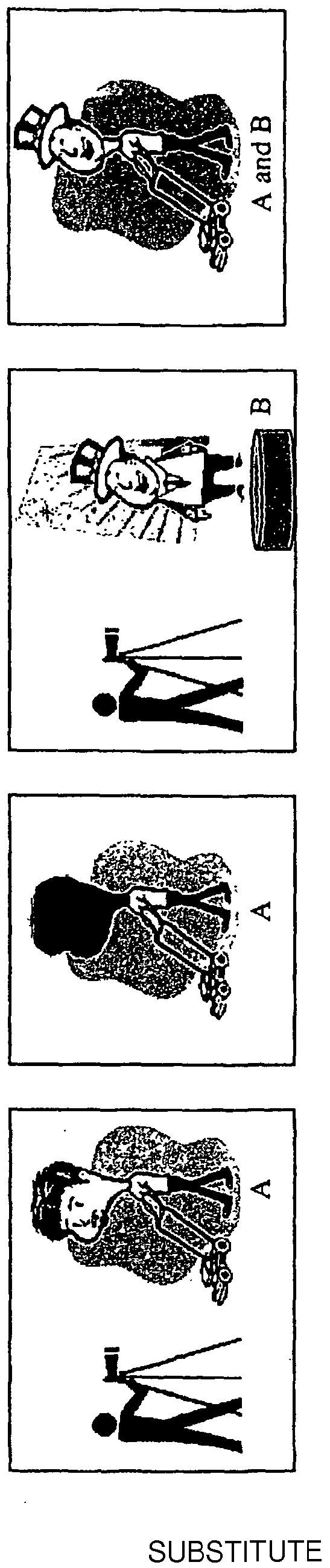
- FIG. 4 depicts a high level block diagram of an AIVlP system 400 of the present invention, such as the AlVIP system of FIG. 1 , where the positioning of the second object 108 relative to the second camera is controlled by the processing and control unit 1 10. That is and as depicted in the embodiment of the present invention of FIG.
- the second camera 104 is fixed and the second object 108 is located on a movable device 1 12 (e.g., a movable stage) such that the second object may be positioned (e.g., rotated, raised; lowered, angled; etc.) by the processing and " control unit 1 10 to put the second camera 104 and the second object 108 in the proper relative positioning as the positioning between the first camera 102 and the first object 106 when the first camera 102 captured the image of the first object 106. That is, the movement of the second object 108 is controlled by the processing and control unit 1 10 using the metadata recorded during the Content Creation process 310.
- a movable device 1 12 e.g., a movable stage
- FIG. 5 depicts a high level block diagram of an AIVIP system 500 of the present invention, such as the AIVIP system of FIG. 1 , where the positioning of the second camera 104 relative to the second object 108 is controlled by the processing and control unit 1 10. That is and as depicted in the embodiment of the present invention of FIG.
- the second object 108 is fixed and the second camera 104 is positioned (e.g., rotated, raised, lowered, angled, etc.) by the processing and control unit 110 to put the second camera 104 and the second object 108 in the proper relative positioning as the positions of the first camera 102 and the first object 106 when the first camera 102 captured the image of the first object 106. That is, the movement of the second camera 104 is controlled by the processing and control unit 110 using the metadata recorded during the Content Creation process 310. As depicted in FIG.
- the second camera 104 may be located on a movable device 112 (e.g., a movable stage) such that the second camera 104 may be positioned (e.g., rotated, raised, lowered, angled, etc.) by the processing and control unit 110.
- a movable device 112 e.g., a movable stage
- the second camera 104 may be positioned (e.g., rotated, raised, lowered, angled, etc.) by the processing and control unit 110.
- the positioning of either the second camera 104 or the second object 108, or any combination thereof are controlled by the processing and control unit 110 to put the second camera 104 and the second object 108 in the proper relative positioning as the positions of the first camera 102 and the first object 106 when the first camera 102 captured the image of the first object 106.
- the processing and control unit 1 10 may be further adapted to control other conditions that may affect the imaging process, such as lighting, temperature and the like, such thai the processing and control unit 1 10 is able to substantially emulate lhc imaging conditions of when the first camera 102 captured the image of the first object 106 for an instance when the second camera 104 captures the image of the second object 108 to be inserted into the original image.
- the new image/video is captured it is scaled and appropriately modified so ' that it is able to be integrated into the matte created from the original video.
- the scaling/modification process is a "best fit" process. That is, variations in between contours of the image to be inserted and the matte prevent an exact match. Consequently, the image to be inserted is proportionally scaled to "cover" as much of the matte area as possible.
- the matte elements are replaced by "cloning" adjacent background pixels.
- the final image/video comprises a combination of the original image/video and the subsequently captured alternate image/video.
- FIG. 6 depicts a flow diagram of a method of alternate video insertion in accordance with an embodiment oi " the present invention.
- the method 600 of FIG. 6 is entered at step 602 where metadata regarding the capture of original video content is stored, the video content having identified areas that are able to be replaced with alternate image/video content.
- the method 600 then proceeds to step 604.
- step 604 the original video content is processed to create a time-stamped matte for each area in the original video able to be replaced.
- the method 600 then proceeds to step 606.
- step 606 an alternate image/video to be inserted into the original video content is captured using the stored metadata identifying the original video content.
- the method 600 then proceeds to step 608.
- the captured alternate image/video is scaled and appropriately modified so that it is able to be integrated into the matte created from the original video.
- the method 600 is then exited.
Abstract
Description
Claims


Priority Applications (8)
| Application Number | Priority Date | Filing Date | Title |
|---|---|---|---|
| CA2613998A CA2613998C (en) | 2005-06-08 | 2005-06-08 | Method, apparatus and system for alternate image/video insertion |
| DE602005022779T DE602005022779D1 (en) | 2005-06-08 | 2005-06-08 | METHOD AND DEVICE FOR ALTERNATING IMAGE VIDEO INSERT |
| CNA2005800500444A CN101213833A (en) | 2005-06-08 | 2005-06-08 | Method, device and system for alternate image/video insertion |
| EP05759385A EP1889471B1 (en) | 2005-06-08 | 2005-06-08 | Method and apparatus for alternate image/video insertion |
| PCT/US2005/020229 WO2006135358A1 (en) | 2005-06-08 | 2005-06-08 | Method, apparatus and system for alternate image/video insertion |
| JP2008515673A JP2008544604A (en) | 2005-06-08 | 2005-06-08 | Alternative image / video insertion method, apparatus and system |
| US11/921,602 US8768099B2 (en) | 2005-06-08 | 2005-06-08 | Method, apparatus and system for alternate image/video insertion |
| KR1020077028629A KR101105916B1 (en) | 2005-06-08 | 2005-06-08 | Method, apparatus and system for alternate image/video insertion |
Applications Claiming Priority (1)
| Application Number | Priority Date | Filing Date | Title |
|---|---|---|---|
| PCT/US2005/020229 WO2006135358A1 (en) | 2005-06-08 | 2005-06-08 | Method, apparatus and system for alternate image/video insertion |
Publications (1)
| Publication Number | Publication Date |
|---|---|
| WO2006135358A1 true WO2006135358A1 (en) | 2006-12-21 |
Family
ID=35734932
Family Applications (1)
| Application Number | Title | Priority Date | Filing Date |
|---|---|---|---|
| PCT/US2005/020229 WO2006135358A1 (en) | 2005-06-08 | 2005-06-08 | Method, apparatus and system for alternate image/video insertion |
Country Status (8)
| Country | Link |
|---|---|
| US (1) | US8768099B2 (en) |
| EP (1) | EP1889471B1 (en) |
| JP (1) | JP2008544604A (en) |
| KR (1) | KR101105916B1 (en) |
| CN (1) | CN101213833A (en) |
| CA (1) | CA2613998C (en) |
| DE (1) | DE602005022779D1 (en) |
| WO (1) | WO2006135358A1 (en) |
Cited By (6)
| Publication number | Priority date | Publication date | Assignee | Title |
|---|---|---|---|---|
| CN102118576A (en) * | 2009-12-30 | 2011-07-06 | 新奥特(北京)视频技术有限公司 | Method and device for color key synthesis in virtual sports system |
| US8660544B2 (en) | 2007-09-19 | 2014-02-25 | Lg Electronics Inc. | Mobile terminal, method of displaying data therein and method of editing data therein |
| US9143721B2 (en) | 2008-07-01 | 2015-09-22 | Noo Inc. | Content preparation systems and methods for interactive video systems |
| CN104967902A (en) * | 2014-09-17 | 2015-10-07 | 腾讯科技(北京)有限公司 | Video sharing method, apparatus and system |
| CN107920274A (en) * | 2017-10-27 | 2018-04-17 | 优酷网络技术(北京)有限公司 | A kind of method for processing video frequency, client and server |
| US10332560B2 (en) | 2013-05-06 | 2019-06-25 | Noo Inc. | Audio-video compositing and effects |
Families Citing this family (18)
| Publication number | Priority date | Publication date | Assignee | Title |
|---|---|---|---|---|
| DE602005022779D1 (en) * | 2005-06-08 | 2010-09-16 | Thomson Licensing | METHOD AND DEVICE FOR ALTERNATING IMAGE VIDEO INSERT |
| US7697827B2 (en) | 2005-10-17 | 2010-04-13 | Konicek Jeffrey C | User-friendlier interfaces for a camera |
| CN101449293A (en) * | 2006-05-31 | 2009-06-03 | 汤姆森许可贸易公司 | Multi-track of video objects |
| US8520972B2 (en) * | 2008-09-12 | 2013-08-27 | Adobe Systems Incorporated | Image decomposition |
| CN101430791B (en) * | 2008-11-14 | 2012-02-08 | 深圳市迅雷网络技术有限公司 | Method and apparatus for synthesizing photo frame on picture |
| JP2010217679A (en) * | 2009-03-18 | 2010-09-30 | Takeshi Ito | Video display method |
| US20120002061A1 (en) * | 2010-07-01 | 2012-01-05 | Gay Michael F | Systems and methods to overlay remote and local video feeds |
| CN103096101B (en) * | 2011-11-07 | 2016-03-30 | 联想(北京)有限公司 | Image synthesizing method, device and electronic equipment |
| KR101397461B1 (en) * | 2012-12-13 | 2014-05-23 | (유)어나더레인보우 | Apparatus and method for compositing the images in real-time |
| CN103248830A (en) * | 2013-04-10 | 2013-08-14 | 东南大学 | Real-time video combination method for augmented reality scene of mobile intelligent terminal |
| CN104125412B (en) * | 2014-06-16 | 2018-07-06 | 联想(北京)有限公司 | A kind of information processing method and electronic equipment |
| KR101936270B1 (en) | 2015-05-26 | 2019-01-08 | 전자부품연구원 | Transforming method of content object data |
| CN105320412B (en) * | 2015-05-28 | 2019-05-17 | 广东维沃软件技术有限公司 | The processing method and mobile terminal of video file |
| CN105306468B (en) * | 2015-10-30 | 2019-01-11 | 广州华多网络科技有限公司 | A kind of method and its main broadcaster's client of synthetic video real-time data sharing |
| CN107820013A (en) * | 2017-11-24 | 2018-03-20 | 上海创功通讯技术有限公司 | A kind of photographic method and terminal |
| US11109042B2 (en) | 2018-05-31 | 2021-08-31 | Apple Inc. | Efficient coding of video data in the presence of video annotations |
| CN108810562B (en) * | 2018-06-21 | 2021-04-06 | 北京密境和风科技有限公司 | Method and device for realizing network performance |
| CN110213629B (en) * | 2019-06-27 | 2022-02-11 | 腾讯科技(深圳)有限公司 | Information implantation method, device, server and storage medium |
Citations (4)
| Publication number | Priority date | Publication date | Assignee | Title |
|---|---|---|---|---|
| US6072537A (en) * | 1997-01-06 | 2000-06-06 | U-R Star Ltd. | Systems for producing personalized video clips |
| US6476874B1 (en) * | 1996-11-19 | 2002-11-05 | Sony Corporation | Apparatus and method for combining background images with main images |
| US6559884B1 (en) * | 1997-09-12 | 2003-05-06 | Orad Hi-Tec Systems, Ltd. | Virtual studio position sensing system |
| FR2854301A1 (en) * | 2003-04-24 | 2004-10-29 | Yodea | Video camera position coordinates transmitting process, involves acquiring data signals during movement of video camera along trajectory for transmitting to sub-system having processing unit to process data |
Family Cites Families (55)
| Publication number | Priority date | Publication date | Assignee | Title |
|---|---|---|---|---|
| US3682540A (en) * | 1969-03-10 | 1972-08-08 | Berkey Photo Inc | Projection optical printing apparatus |
| US4249805A (en) * | 1979-03-26 | 1981-02-10 | Magicam, Inc. | Composite photography system |
| JPS61252780A (en) | 1985-04-30 | 1986-11-10 | Shimadzu Corp | Digital subtraction device |
| JPH065932B2 (en) * | 1986-05-28 | 1994-01-19 | 富士写真フイルム株式会社 | Image recorder |
| JPH01153521A (en) | 1987-12-09 | 1989-06-15 | Nkk Corp | Production of superconducting material |
| US4972494A (en) * | 1988-02-26 | 1990-11-20 | R. J. Reynolds Tobacco Company | Package inspection system |
| US5264837A (en) | 1991-10-31 | 1993-11-23 | International Business Machines Corporation | Video insertion processing system |
| FR2697360B1 (en) | 1992-10-26 | 1994-12-30 | Jeux Franc | Acquisition and playback system of a sequence of animated video images in real time. |
| JPH06292052A (en) | 1993-04-02 | 1994-10-18 | Sharp Corp | Still picture image pickup device |
| US5681223A (en) * | 1993-08-20 | 1997-10-28 | Inventures Inc | Training video method and display |
| JPH07240897A (en) | 1994-03-01 | 1995-09-12 | Victor Co Of Japan Ltd | Video signal recorder |
| US6400374B2 (en) * | 1996-09-18 | 2002-06-04 | Eyematic Interfaces, Inc. | Video superposition system and method |
| US6100925A (en) * | 1996-11-27 | 2000-08-08 | Princeton Video Image, Inc. | Image insertion in video streams using a combination of physical sensors and pattern recognition |
| US5764306A (en) | 1997-03-18 | 1998-06-09 | The Metaphor Group | Real-time method of digitally altering a video data stream to remove portions of the original image and substitute elements to create a new image |
| US6449310B1 (en) | 1997-11-21 | 2002-09-10 | Matsushita Electric Industrial Co., Ltd. | Video signal coding apparatus |
| US6577760B1 (en) | 1997-12-18 | 2003-06-10 | Fuji Photo Film Co., Ltd. | Image processing apparatus and method, image synthesizing system and method, image synthesizer and client computer which constitute image synthesizing system, and image separating method |
| US6278479B1 (en) | 1998-02-24 | 2001-08-21 | Wilson, Hewitt & Associates, Inc. | Dual reality system |
| US6134345A (en) * | 1998-08-28 | 2000-10-17 | Ultimatte Corporation | Comprehensive method for removing from an image the background surrounding a selected subject |
| US6714249B2 (en) * | 1998-12-31 | 2004-03-30 | Eastman Kodak Company | Producing panoramic digital images by digital camera systems |
| US6909743B1 (en) * | 1999-04-14 | 2005-06-21 | Sarnoff Corporation | Method for generating and processing transition streams |
| US6906744B1 (en) * | 1999-09-28 | 2005-06-14 | Nikon Corporation | Electronic camera |
| US7230653B1 (en) * | 1999-11-08 | 2007-06-12 | Vistas Unlimited | Method and apparatus for real time insertion of images into video |
| US6308016B1 (en) | 2000-01-28 | 2001-10-23 | Eastman Kodak Company | Verifing camera with demonstration mode and method |
| AU4747800A (en) * | 2000-04-14 | 2001-10-30 | Orlean Holding N.V. | An improved system and method for digitally editing a composite image |
| US6778207B1 (en) | 2000-08-07 | 2004-08-17 | Koninklijke Philips Electronics N.V. | Fast digital pan tilt zoom video |
| JP2002055640A (en) | 2000-08-10 | 2002-02-20 | Takao Yoguchi | Device for display of image-change |
| JP2002135565A (en) | 2000-10-27 | 2002-05-10 | Fuji Xerox Co Ltd | Image forming device |
| JP2002232782A (en) | 2001-02-06 | 2002-08-16 | Sony Corp | Image processor, method therefor and record medium for program |
| FR2826130A1 (en) | 2001-06-15 | 2002-12-20 | Gerard Roch Desbornes | Device for relief image adapting, for the formation of three-dimensional images totally interactive with a physical video image issuing from the same source |
| US20030007700A1 (en) * | 2001-07-03 | 2003-01-09 | Koninklijke Philips Electronics N.V. | Method and apparatus for interleaving a user image in an original image sequence |
| WO2003005299A2 (en) | 2001-07-06 | 2003-01-16 | Vision Iii Imaging, Inc. | Image segmentation by means of temporal parallax difference induction |
| JP2003338972A (en) * | 2001-09-12 | 2003-11-28 | Fuji Photo Film Co Ltd | Image processing system, imaging unit, apparatus and method for processing image and program |
| US20030159153A1 (en) * | 2002-02-20 | 2003-08-21 | General Instrument Corporation | Method and apparatus for processing ATVEF data to control the display of text and images |
| EP1370075B1 (en) * | 2002-06-06 | 2012-10-03 | Accenture Global Services Limited | Dynamic replacement of the face of an actor in a video movie |
| JP2004038746A (en) | 2002-07-05 | 2004-02-05 | Toshiba Corp | Image editing method and image editing system |
| US7084876B1 (en) * | 2002-12-07 | 2006-08-01 | Digenetics, Inc. | Method for presenting a virtual reality environment for an interaction |
| SE0300286D0 (en) * | 2003-02-05 | 2003-02-05 | Axis Ab | Method and apparatus for combining video signals into one comprehensive video signal |
| GB2402567B (en) * | 2003-04-05 | 2006-07-19 | Autodesk Canada Inc | Image processing |
| US7324166B1 (en) * | 2003-11-14 | 2008-01-29 | Contour Entertainment Inc | Live actor integration in pre-recorded well known video |
| TWI230315B (en) * | 2004-01-16 | 2005-04-01 | Pixart Imaging Inc | An image capture device and a method of the image exposure process |
| US8659619B2 (en) * | 2004-03-26 | 2014-02-25 | Intellectual Ventures Fund 83 Llc | Display device and method for determining an area of importance in an original image |
| US8205154B2 (en) * | 2004-04-16 | 2012-06-19 | Apple Inc. | User definable transition tool |
| US7639387B2 (en) * | 2005-08-23 | 2009-12-29 | Ricoh Co., Ltd. | Authoring tools using a mixed media environment |
| JP4251650B2 (en) * | 2005-03-28 | 2009-04-08 | 株式会社カシオ日立モバイルコミュニケーションズ | Image processing apparatus and program |
| DE602005022779D1 (en) * | 2005-06-08 | 2010-09-16 | Thomson Licensing | METHOD AND DEVICE FOR ALTERNATING IMAGE VIDEO INSERT |
| US20070027844A1 (en) * | 2005-07-28 | 2007-02-01 | Microsoft Corporation | Navigating recorded multimedia content using keywords or phrases |
| US20070099699A1 (en) * | 2005-10-28 | 2007-05-03 | Anatoly Plotkin | Novel enhanced image entertainment and laser engraving site and method of engraving an image |
| US7724952B2 (en) * | 2006-05-15 | 2010-05-25 | Microsoft Corporation | Object matting using flash and no-flash images |
| JP2008103784A (en) * | 2006-10-17 | 2008-05-01 | Hitachi Ltd | Video recording device |
| JP4395789B2 (en) * | 2006-10-30 | 2010-01-13 | ソニー株式会社 | Image processing apparatus, imaging apparatus, image processing method, and program |
| US8824861B2 (en) * | 2008-07-01 | 2014-09-02 | Yoostar Entertainment Group, Inc. | Interactive systems and methods for video compositing |
| US20110211749A1 (en) * | 2010-02-28 | 2011-09-01 | Kar Han Tan | System And Method For Processing Video Using Depth Sensor Information |
| US8913847B2 (en) * | 2010-06-01 | 2014-12-16 | Hewlett-Packard Development Company, L.P. | Replacement of a person or object in an image |
| US8386964B2 (en) * | 2010-07-21 | 2013-02-26 | Microsoft Corporation | Interactive image matting |
| US20120308211A1 (en) * | 2011-06-01 | 2012-12-06 | Xerox Corporation | Asynchronous personalization of records using dynamic scripting |
-
2005
- 2005-06-08 DE DE602005022779T patent/DE602005022779D1/en active Active
- 2005-06-08 KR KR1020077028629A patent/KR101105916B1/en not_active IP Right Cessation
- 2005-06-08 JP JP2008515673A patent/JP2008544604A/en active Pending
- 2005-06-08 EP EP05759385A patent/EP1889471B1/en not_active Expired - Fee Related
- 2005-06-08 US US11/921,602 patent/US8768099B2/en not_active Expired - Fee Related
- 2005-06-08 CA CA2613998A patent/CA2613998C/en not_active Expired - Fee Related
- 2005-06-08 CN CNA2005800500444A patent/CN101213833A/en active Pending
- 2005-06-08 WO PCT/US2005/020229 patent/WO2006135358A1/en active Application Filing
Patent Citations (4)
| Publication number | Priority date | Publication date | Assignee | Title |
|---|---|---|---|---|
| US6476874B1 (en) * | 1996-11-19 | 2002-11-05 | Sony Corporation | Apparatus and method for combining background images with main images |
| US6072537A (en) * | 1997-01-06 | 2000-06-06 | U-R Star Ltd. | Systems for producing personalized video clips |
| US6559884B1 (en) * | 1997-09-12 | 2003-05-06 | Orad Hi-Tec Systems, Ltd. | Virtual studio position sensing system |
| FR2854301A1 (en) * | 2003-04-24 | 2004-10-29 | Yodea | Video camera position coordinates transmitting process, involves acquiring data signals during movement of video camera along trajectory for transmitting to sub-system having processing unit to process data |
Cited By (7)
| Publication number | Priority date | Publication date | Assignee | Title |
|---|---|---|---|---|
| US8660544B2 (en) | 2007-09-19 | 2014-02-25 | Lg Electronics Inc. | Mobile terminal, method of displaying data therein and method of editing data therein |
| US9143721B2 (en) | 2008-07-01 | 2015-09-22 | Noo Inc. | Content preparation systems and methods for interactive video systems |
| CN102118576A (en) * | 2009-12-30 | 2011-07-06 | 新奥特(北京)视频技术有限公司 | Method and device for color key synthesis in virtual sports system |
| US10332560B2 (en) | 2013-05-06 | 2019-06-25 | Noo Inc. | Audio-video compositing and effects |
| CN104967902A (en) * | 2014-09-17 | 2015-10-07 | 腾讯科技(北京)有限公司 | Video sharing method, apparatus and system |
| CN104967902B (en) * | 2014-09-17 | 2018-10-12 | 腾讯科技(北京)有限公司 | Video sharing method, apparatus and system |
| CN107920274A (en) * | 2017-10-27 | 2018-04-17 | 优酷网络技术(北京)有限公司 | A kind of method for processing video frequency, client and server |
Also Published As
| Publication number | Publication date |
|---|---|
| DE602005022779D1 (en) | 2010-09-16 |
| KR20080016616A (en) | 2008-02-21 |
| CA2613998C (en) | 2016-01-05 |
| CA2613998A1 (en) | 2006-12-21 |
| US20100278450A1 (en) | 2010-11-04 |
| KR101105916B1 (en) | 2012-01-17 |
| EP1889471A1 (en) | 2008-02-20 |
| US8768099B2 (en) | 2014-07-01 |
| JP2008544604A (en) | 2008-12-04 |
| CN101213833A (en) | 2008-07-02 |
| EP1889471B1 (en) | 2010-08-04 |
Similar Documents
| Publication | Publication Date | Title |
|---|---|---|
| US8768099B2 (en) | Method, apparatus and system for alternate image/video insertion | |
| US9692964B2 (en) | Modification of post-viewing parameters for digital images using image region or feature information | |
| CA2284032C (en) | Real-time method of digitally altering a video data stream to remove portions of the original image and substitute elements to create a new image | |
| US8675991B2 (en) | Modification of post-viewing parameters for digital images using region or feature information | |
| US9129381B2 (en) | Modification of post-viewing parameters for digital images using image region or feature information | |
| US5737031A (en) | System for producing a shadow of an object in a chroma key environment | |
| US20030202120A1 (en) | Virtual lighting system | |
| US20170134714A1 (en) | Device and method for creating videoclips from omnidirectional video | |
| JP6672305B2 (en) | Method and apparatus for generating extrapolated images based on object detection | |
| KR20150108774A (en) | Method for processing a video sequence, corresponding device, computer program and non-transitory computer-readable medium | |
| EP3044952A1 (en) | Depth key compositing for video and holographic projection | |
| KR102061152B1 (en) | System for providing ar service and method for generating 360 angle rotatable image file thereof | |
| WO1997028654A2 (en) | Chroma keying studio system | |
| US20220114734A1 (en) | System for background and floor replacement in full-length subject images | |
| CN110446092B (en) | Virtual auditorium generation method, system, device and medium for sports game | |
| JP2005223487A (en) | Digital camera work apparatus, digital camera work method, and digital camera work program | |
| CN108055423B (en) | Multi-lens video synchronization offset calculation method | |
| JP2007233647A (en) | Presentation data processing apparatus | |
| KR20050015737A (en) | Real image synthetic process by illumination control | |
| CN107911686B (en) | Control method and camera shooting terminal | |
| Bimber et al. | Digital illumination for augmented studios | |
| JPS60239189A (en) | Method for separating and identifying object | |
| CN102457677A (en) | Image reproduction device, image reproduction method and program | |
| Xu et al. | Framework for script based virtual directing and multimedia authoring in live video streaming | |
| Thomas | Virtual Graphics for Broadcast Production |
Legal Events
| Date | Code | Title | Description |
|---|---|---|---|
| WWE | Wipo information: entry into national phase |
Ref document number: 200580050044.4 Country of ref document: CN |
|
| 121 | Ep: the epo has been informed by wipo that ep was designated in this application | ||
| WWE | Wipo information: entry into national phase |
Ref document number: 9102/DELNP/2007 Country of ref document: IN |
|
| ENP | Entry into the national phase |
Ref document number: 2613998 Country of ref document: CA |
|
| WWE | Wipo information: entry into national phase |
Ref document number: 2005759385 Country of ref document: EP |
|
| ENP | Entry into the national phase |
Ref document number: 2008515673 Country of ref document: JP Kind code of ref document: A |
|
| WWE | Wipo information: entry into national phase |
Ref document number: 1020077028629 Country of ref document: KR |
|
| NENP | Non-entry into the national phase |
Ref country code: DE |
|
| WWP | Wipo information: published in national office |
Ref document number: 2005759385 Country of ref document: EP |
|
| WWE | Wipo information: entry into national phase |
Ref document number: 11921602 Country of ref document: US |