WO2006125648A2 - Device and method for coating substrates with catalytically active materials - Google Patents

Device and method for coating substrates with catalytically active materials Download PDF

Info

Publication number
WO2006125648A2
WO2006125648A2 PCT/EP2006/005000 EP2006005000W WO2006125648A2 WO 2006125648 A2 WO2006125648 A2 WO 2006125648A2 EP 2006005000 W EP2006005000 W EP 2006005000W WO 2006125648 A2 WO2006125648 A2 WO 2006125648A2
Authority
WO
WIPO (PCT)
Prior art keywords
liquid phase
honeycomb
channels
shaped body
oscillating plate
Prior art date
Application number
PCT/EP2006/005000
Other languages
German (de)
French (fr)
Other versions
WO2006125648A3 (en
Inventor
Hans-Jürgen EBERLE
Olaf Helmer
Jörg SPENGLER
Original Assignee
Süd-Chemie AG
Priority date (The priority date is an assumption and is not a legal conclusion. Google has not performed a legal analysis and makes no representation as to the accuracy of the date listed.)
Filing date
Publication date
Application filed by Süd-Chemie AG filed Critical Süd-Chemie AG
Priority to US11/915,369 priority Critical patent/US20080182020A1/en
Priority to CA002605285A priority patent/CA2605285A1/en
Priority to EP06753869A priority patent/EP1885494A2/en
Publication of WO2006125648A2 publication Critical patent/WO2006125648A2/en
Publication of WO2006125648A3 publication Critical patent/WO2006125648A3/en

Links

Classifications

    • B01J35/56
    • BPERFORMING OPERATIONS; TRANSPORTING
    • B01PHYSICAL OR CHEMICAL PROCESSES OR APPARATUS IN GENERAL
    • B01JCHEMICAL OR PHYSICAL PROCESSES, e.g. CATALYSIS OR COLLOID CHEMISTRY; THEIR RELEVANT APPARATUS
    • B01J37/00Processes, in general, for preparing catalysts; Processes, in general, for activation of catalysts
    • B01J37/02Impregnation, coating or precipitation
    • B01J37/0215Coating
    • FMECHANICAL ENGINEERING; LIGHTING; HEATING; WEAPONS; BLASTING
    • F01MACHINES OR ENGINES IN GENERAL; ENGINE PLANTS IN GENERAL; STEAM ENGINES
    • F01NGAS-FLOW SILENCERS OR EXHAUST APPARATUS FOR MACHINES OR ENGINES IN GENERAL; GAS-FLOW SILENCERS OR EXHAUST APPARATUS FOR INTERNAL COMBUSTION ENGINES
    • F01N3/00Exhaust or silencing apparatus having means for purifying, rendering innocuous, or otherwise treating exhaust
    • F01N3/08Exhaust or silencing apparatus having means for purifying, rendering innocuous, or otherwise treating exhaust for rendering innocuous
    • F01N3/10Exhaust or silencing apparatus having means for purifying, rendering innocuous, or otherwise treating exhaust for rendering innocuous by thermal or catalytic conversion of noxious components of exhaust
    • F01N3/24Exhaust or silencing apparatus having means for purifying, rendering innocuous, or otherwise treating exhaust for rendering innocuous by thermal or catalytic conversion of noxious components of exhaust characterised by constructional aspects of converting apparatus
    • F01N3/28Construction of catalytic reactors
    • F01N3/2803Construction of catalytic reactors characterised by structure, by material or by manufacturing of catalyst support

Definitions

  • the invention relates to an apparatus and a method for the production of catalysts and their use in the purification of exhaust gases.
  • the invention relates to a method and a device for producing monolithic and porous catalysts by applying a washcoat suspension to moldings (eg honeycomb bodies, in short honeycomb or metal foam body) which have channels and / or pores, and to the use of the supported materials obtained in this way Catalysts in the purification of exhaust gases from internal combustion engines.
  • moldings eg honeycomb bodies, in short honeycomb or metal foam body
  • Monolithic or porous catalysts for the purification of exhaust gases such as the oxidation of CO or hydrocarbons to CO2 and water or the reduction of NO x with ammonia or urea to N 2 and water or the decomposition of urea or its thermal decomposition product, the isocyanic acid, to ammonia and CO 2 , have long been known.
  • these catalysts are constructed in such a way that a perforated with channels or pores shaped body serves as a carrier material having a high surface area (high surface area) metal oxide coating (washcoat), for example, Al 2 O 3 , SiO 2 or TiO 2 is coated and the actually catalytically active metals or metal compounds, such as precious metals or transition metal oxides, and optionally additional promoter compounds / dopants are applied or already contained on these metal oxide surfaces.
  • washcoat high surface area (high surface area) metal oxide coating
  • Al 2 O 3 , SiO 2 or TiO 2 is coated and the actually catalytically active metals or metal compounds, such as precious metals or transition metal oxides, and optionally additional promoter compounds / dopants are applied or already contained on these metal oxide surfaces.
  • washcoat for example, Al 2 O 3 , SiO 2 or TiO 2
  • washcoat for example, Al 2 O 3 , SiO 2 or TiO 2
  • the actually catalytically active metals or metal compounds such as precious metals or transition
  • the honeycombs generally generally consist of a so-called honeycomb body, which can be composed of a honeycomb casing and a carrier used therein, in particular a partially structured and wound sheet metal foil, or the honeycomb consists overall of a ceramic shaped body.
  • the honeycombs are essentially traversed by running parallel to the axis of the honeycomb channels.
  • the honeycombs have porous channel walls.
  • the porous moldings are preferably made of porous metal or ceramic foams, whose porosity can be adjusted by the manufacturing process. The production of such metal or ceramic foam by means of those skilled in per se known method.
  • honeycomb monolithic carrier
  • the channels running through a so-called monolithic carrier can have an ordered or disordered channel structure, furthermore the essentially parallel channels can also be interconnected (so-called open channel structures)
  • the size of the honeycomb as well as the dimensioning of the channels will depend mainly on the dimension of the exhaust gas piping systems of the exhaust gas composition and the respective application (DeNOX, DPF, etc.) as well as the required pressure losses and the required residence times of the exhaust gas in the catalytic converter.
  • the pore size Distribution is an important factor that can be set by the manufacturing process.
  • honeycombs made of ceramic molded articles for example, materials such as cordierite, steatite, Durace® or silicon carbide or shaped bodies of silicon dioxide, aluminum oxides, aluminates or even metals and metal alloys are used.
  • metals and metal alloys make it possible to produce complex structured honeycomb bodies such as, for example, honeycombs with open channel structures.
  • Porous moldings are preferably made of metals or alloys ("metal foam"), but also the above-mentioned ceramic materials for the production of porous Formkorper (“ceramic foam”) are suitable.
  • the geometric shape is not limited to a single shape as long as there are 2 face planes substantially parallel to each other, but typically cylindrical shapes are preferred.
  • the preparation of a catalyst as described above is generally carried out by the application of a so-called washcoat (WC) on the channel walls (coating) or on the pore walls, followed by drying followed by calcination at higher temperatures to solidify and finalize the washcoat finish. Thereafter, the catalytically active components are applied to the washcoat by impregnation steps, usually from the aqueous solutions of their precursors. But it is also possible to apply the active components or their precursor compounds directly with the coating process.
  • WC washcoat
  • the coating of a shaped body with the inorganic highly superficial materials is possible by various methods.
  • a suspension of the inorganic carrier oxide in water is first prepared, if appropriate with the addition of additives, such as inorganic binders, surfactants, catalytic active components, pore formers, rheology aids and other additives, and the molding by a dipping, suction or pumping process filled with this so-called washcoat suspension.
  • additives such as inorganic binders, surfactants, catalytic active components, pore formers, rheology aids and other additives
  • complex-structured honeycomb or porous shaped bodies are meant honeycombs whose channels have elevations or depressions or blades and thus turbulences are specifically generated in the gas stream, which also lead to a better mass transfer and thus higher activities.
  • Open structures are also part of this type of support; In the case of open structures, as already described above, the channels are connected to one another by corresponding perforations (holes, pores). As a result, in addition to a vertical direction of flow (parallel to the channel axis), a more or less horizontal (radially to the axis of the honeycomb or channels) gas flow is possible. Also porous metal foams are among the complex structures due to the irregular arrangement of the pores. With complex structures, it is possible to produce catalysts which simultaneously have a mixing effect. Furthermore, of course, combinations of purely plane-parallel and complex structured honeycomb are conceivable.
  • honeycombs and porous moldings with high cell densities as well as honeycombs with complex structured and perforated channels (open structures) can be produced by the previously known methods no longer be coated without much effort. In particular, the blowing out of the excess washcoat suspension with air is no longer possible with open channel structures or pores.
  • blow-out air will basically take the path of least resistance (least pressure loss path).
  • the blown-out air used in the sequence will pass through the holes of the open structures or pores into those already open channels or interconnected pore system and the pressure of the blow-out air used is regularly not sufficient to blow down the washcoat suspension from still partially filled channels or pores, in which the washcoat suspension is held by capillary forces.
  • the pressure of the blow-out air used is regularly not sufficient to blow down the washcoat suspension from still partially filled channels or pores, in which the washcoat suspension is held by capillary forces.
  • a few completely emptied by blowing channels or pores or pore systems lead to the effect described, so that only a few channels or parts of the channels are to be emptied by blowing alone.
  • FIG. 1 shows a partial view of two parallel channels of a honeycomb which are connected to one another via a perforation (open structure). While the channel shown on the right already has been freed of excess washcoat by the blow-off air (the flow direction of the air is illustrated by the arrows), this is no longer possible in the channel shown on the left for the reason described, so that it is no longer blow-out alone remains to be removed and held by the capillary force remains washcoat in the lower part of the channel. If the air flow increased so far is that all channels or parts of the channels are free, is then too little washcoat on the carrier.
  • internal cavity is meant here pores, holes, recesses, or at least partially interconnected pores or pore systems. [Typ Typ] Typically, the internal cavities pass through the entire shaped body.
  • inter cavities is also meant the open and / or complex channel systems of honeycombs described above, as well as porous porous body systems, such as metal and ceramic foams.
  • the object was to provide a method for the liberation or emptying of honeycombs and porous moldings with open and / or complex structures of wastecoat used washcoat suspension that solves the above problems.
  • the solution should be characterized by measures that are easy to implement.
  • centrifugal force is meant the force acting on a body when subjected to acceleration and / or deceleration processes.
  • a centrifugal force defined according to the invention can thus e.g. not be generated by vibrations.
  • the body and the liquid therein are accelerated and or decelerated in such a way that the applied deceleration is greater in magnitude than the amount of acceleration previously applied.
  • the delay or deceleration of the to be emptied or of the excess of the washcoat to be liberated molded article must therefore be greater - ultimately done faster - than the previously used acceleration. Furthermore, the delay must also be so high that the inertia force occurring in this case is greater than the forces acting between the individual liquid layers of the washcoat, in particular the capillary and frictional forces which prevent the excess from flowing out.
  • the layer thickness of the applied washcoat is correlated with the deceleration force.
  • monolithic and on metal or ceramic foams based ing catalysts in particular so-called support oxide-based catalysts, which are used, inter alia, as catalysts in the purification of exhaust gases.
  • the principle according to the invention can be used completely analogously, conversely, for filling a shaped body as defined above.
  • a highly viscous liquid can be introduced by repeated accelerations and subsequent braking into narrow inner cavities or channels of a shaped body which are at least partially connected to each other or to the surface of the shaped body.
  • a further subject of the invention is a method for filling a molded body having a plurality of internal cavities and / or channels with a liquid phase, wherein the filling of the internal cavities takes place with the aid of an acceleration process and a downstream delay operation (also referred to as deceleration process). and wherein the deceleration is faster than the previous acceleration, with the proviso that the gravitational forces induced by the deceleration and acting on the liquid phase are greater than the sum of the other opposing forces also acting on the liquid phase.
  • the principle according to the invention can basically be used with any liquid phase which is or should be introduced into the internal cavities, such as channels and pores of such a shaped body.
  • the liquid phase is a washcoat suspension, but the liquid phase can also comprise, for example, solutions or low-viscosity suspensions with the aid of which subsequently catalytically active substances or precursor compounds are applied to a precoated molded body or carrier body.
  • Tragerkor- per, honeycomb, honeycomb body and metal foam are below as Be synonymous or understood as having the same effect as the term "shaped article" used according to the invention.
  • the inventive principle for applying and removing an excess of a washcoat suspension is used.
  • this embodiment of the method according to the invention will be described by way of example, but this is in no way to be understood as a restriction, since the principle according to the invention can be transferred to all liquid phases in an analogous manner.
  • the principle of the method according to the invention is based on the fact that the delay causes an impulse to act on the liquid phase present in the channels or pores, in particular an excess washcoat suspension, this impulse having to be greater in magnitude than the sum of the others liquid phase acting forces, especially the capillary and friction forces.
  • the effect of the filling and emptying principle according to the invention is not tied to the specific measure for carrying out the acceleration or deceleration or deceleration and, in principle, completely independent of its concrete design.
  • the acceleration can be brought about simply by gravity (for example the free fall of a filled molded body or sliding on an oblique plane) or the acceleration is effected by a force acting on the shaped body, for example a spring force or a spring force Force resulting from a hydraulic or pneumatic device causes.
  • a force acting on the shaped body for example a spring force or a spring force Force resulting from a hydraulic or pneumatic device causes.
  • the force occurring during braking (deceleration) is of course greater, the faster the deceleration takes place.
  • the delay can be done in the simplest case by the impact on a corresponding stationary and fixed brake plate. But it is also possible that the deceleration is effected by a Tragerkorper the counter-moving brake plate.
  • the body to be emptied is decelerated even faster, which usually leads to a further improved emptying result.
  • inventive emptying process acceleration and subsequent deceleration
  • the force impulse required for emptying depends on the nature of the liquid phase, in particular the washcoat suspension and on the size of the capillary forces, which act like pores and channels within the internal cavities and depend on their dimensioning.
  • the braking force must at least overcome the friction between the fluid layers in order to bring about the success of the principle according to the invention.
  • the amount of delay is ten (10) greater than the amount of acceleration by a factor of ten.
  • the delay can also take place in two separate delay phases, wherein (preferably) the amount of delay in the first phase is greater than the amount of delay in the second phase.
  • a device which is also the subject of the present invention and with which the method according to the invention can be carried out, comprises means for producing a centrifugal force acting on the shaped body and the liquid phase.
  • the means for generating a centrifugal force are in particular means for acceleration and / or means for braking.
  • a further device with which the method according to the invention can be carried out, is a drop tube according to FIG. 3.
  • the drop tube comprises a vertically guided, elongated tubular component, in which, for example, the honeycomb to be released from the excess is introduced into the upper region Frame that is firmly connected to the rohrformigen component, a diaphragm ring at the lower end of rohrformigen member, which is designed so that the outer wall of the honeycomb (honeycomb Hul- Ie) rests during braking or the honeycomb the rohrformige component not through the lower Opening can leave (can fall through), so that the honeycomb to be emptied and accelerated by the free fall is abruptly braked, and a collecting vessel for the outflowing excess liquid phase.
  • the foregoing also applies to the porous moldings, e.g. those made of metal or Keramikschau- men.
  • a further device namely an acceleration impact device with a rod according to FIG. 4.
  • a channel having molding ie, for example, a monolith or honeycomb, is used.
  • any other shaped article described above may also be used.
  • the device comprises a swinging plate (1) which is connected to a frame (3) via springs (4) mounted on its underside - preferably four springs respectively arranged at the corners of the swinging plate (1) and with the aid of one or more springs a plurality of unbalance motors (5) can be vibrated, one on the top of the swing plate (1) in turn via springs (6) - preferably in turn via four springs - mounted second swing plate (2) for amplifying the vibration amplitude, one in the center of the second swing plate (2) mounted receiving sleeve (8) for receiving the honeycomb body or the honeycomb (9), wherein the shape of the vibrating plate (2) is selected - preferably a Z-shape - that the running during operation of the device liquid phase, in particular the washcoat suspension, flows into a collecting vessel (7) arranged underneath and the receiving sleeve (8) is designed in such a way - preferably with a diaphragm ring (10) - that the outer wall the honeycomb (9) (honeycomb shell) rests
  • the honeycomb (9) can be fixed in the receiving sleeve (8) or introduced unfixed. If the honeycomb (9) is not fixed in the receiving sleeve, an additional (asynchronous) movement of the honeycomb in the receiving sleeve (8) (deflection height up to 10 cm) occurs after the impact on the diaphragm ring (10).
  • the movement of the honeycomb differs greatly from that of the vibration plate, as the honeycomb moves much slower down.
  • the falling honeycomb encounters relatively frequently an upwardly accelerated oscillating plate (2) or the associated diaphragm ring (10).
  • the thereby acting on the honeycomb delay and the associated pulse is thus significantly higher than in the case of the fixed honeycomb, whereby it comes to an increase of the emptying effect.
  • a further device according to the invention with which the method according to the invention can be carried out is a hydraulically or pneumatically operated emptying device according to FIG. 5.
  • the device according to FIG. 5 comprises a compressed air cylinder or hydraulic cylinder (1), to the piston rod of which a connecting piece (2) is firmly connected, wherein the connecting piece (2) is movable via a guide rail (3) with a stable frame (4) - Bottom) and the connecting piece (2) is further firmly connected to a Hulsenhalterung (7), wherein on the Hulsenhalterung (7) for receiving the honeycomb or the porous Formkorpers (5) has a downwardly and upwardly open cylindricalcounthulse (6 ) whose lower end is designed, preferably by a diaphragm ring, that the outer wall of the honeycomb (5) (honeycomb shell) at Ab- brake operation rests or the honeycomb (9) can not leave the Conshulse (6) through the lower opening (can fall through) and below therachulse (6) on the frame (4) fixed impact plate (8), wherein the impact plate
  • the apparatus according to FIG. 5 is particularly suitable for emptying metallic honeycomb bodies and porous shaped bodies made of metallic or ceramic foams.
  • the inventive method for filling with or for emptying a liquid phase of inner cavities and / or channels having shaped body is based in summary that the liquid filled or teilbefullte shaped body is first accelerated to a speed and then strongly braked again, so that by the delay acting on the liquid phase is greater than the sum of the forces acting on the liquid phase, in particular the capillary and friction forces acting between the liquid layers of the liquid phase in the channels.
  • the shaped articles can also be filled with the liquid phase, in particular the washcoat suspension, by alternative methods, in particular by pumping.
  • a first partial emptying can be carried out according to another functional principle, in particular by suction, purging, centrifuging or simply flowing out.
  • the abovementioned possibilities for partial emptying can also be used in combination with the emptying method according to the invention, in particular successively or simultaneously.
  • the inventive principle for removing the excess of the liquid phase, in particular the washcoat suspension can be used, in particular, as part of a complete coating process of moldings having channels or pores.
  • a further subject of the invention is therefore also a method for coating a shaped body having a liquid phase comprising a plurality of at least partially interconnected internal cavities and / or channels, comprising the following steps
  • step C) removing the excess of liquid phase remaining after step B) from the inner cavities and / or channels of the molded copier to be coated, characterized in that the removal of the excess from the inner cavities takes place by means of an acceleration process and a subsequent delay process (deceleration process), whereby the delay is faster than the previously acceleration followed, with the proviso that the inertia forces produced by the deceleration and acting on the excess liquid phase are greater than the sum of the other opposing forces also acting on the liquid phase.
  • the liquid phase is preferably a washcoat suspension.
  • step C) The removal of the excess remaining after step B) in step C) can be carried out preferably with a drop tube according to FIG. 3 or one of the two devices according to the invention as shown in FIG. 4 or 5.
  • step B) can also be used in combination with any method known to the person skilled in the art for emptying moldings which can be used according to the invention.
  • the application of an air flow directed towards the channels or pores (blowing out) and / or the use of centrifugal forces is used.
  • a variant of step B) may be that the partial emptying of the molded article takes place exclusively by the outflow of the excess liquid phase, in particular the washcoat suspension, due to its own weight and then the emptying is carried out by the emptying process according to the invention by acceleration and deceleration.
  • steps A) and B) are carried out several times in succession before step C) is carried out.
  • steps A) and B) are each run through three times to ensure that all the channels or pores of the shaped body with liquid phase, in particular with Washco at suspension were filled completely at least once.
  • the filling after step A) and / or the partial emptying step B) can be effected by the action of vibrations in order to increase the flow properties of the liquid phase or washcoat suspension to be aspirated or expelled.
  • the filling or partial filling of the moldings with the liquid phase, in particular with the washcoat suspension can take place, for example, with a special device in the form of a piston-cylinder system.
  • the device is explained on the basis of a so-called “honeycomb", but of course corresponding porous metal foams can also be used.
  • This device according to FIG. 2 comprises a piston cylinder
  • Connection plate (b) which is firmly connected to the lower end of the Kolbenzy- Linders and can be tightly connected to the upper end of the honeycomb to be coated, a receiving plate (c) on its upper side with the lower end of the honeycomb to be coated tight optionally, one or more vibration units fixed to the receiving plate (c), a hydraulically movable suspension (f) with which the cylinder unit (a), the connecting plate (b) and the receiving plate (c) are moved horizontally together can (up and down movement), an intake / outlet pipe (d), which is attached to the lower side of the receiving plate (c) and a storage trough (e), in which the Washcoat suspension is presented.
  • the tight connection of the honeycomb to be coated with the connecting plate (b) and the receiving plate (c) is preferred way by pressing the end faces of the honeycomb to corresponding sealing devices on the plates (b) and (c).
  • the connecting plate (b) and the receiving plate (c) are in each case in the area in which they are to take the honeycomb to be filled ⁇ , so that on the one hand on the KoI- benzylinder (a) a pressure or negative pressure can be established and on the other hand, the washcoat suspension can be sucked or pressed out through the suction / discharge pipe (d).
  • the inventive coating method or the emptying method according to the invention make it possible, in particular, to produce monolithic and metal foam-based catalysts which are based on a washcoat consisting essentially of TiO 2 .
  • the catalysts obtainable by the processes according to the invention can be used in particular as catalysts in the purification of exhaust gases, in particular those of internal combustion engines.
  • the catalysts obtainable by the process according to the invention are, in particular, the purification of automobile and diesel exhaust gases.
  • the catalysts prepared by the method according to the invention can be used as decomposition catalysts for ammonia precursor compounds, as oxidation catalysts, as catalysts for the removal of nitrogen oxides and as catalysts for the reduction of nitrogen oxides.
  • novel processes can be used in particular for the preparation of catalysts in which washcoat suspensions consisting of support oxides or support oxide combinations selected from the group comprising TiO 2 , Al 2 O 3 , SiO 2 , CeO 2 , ZrO 2 or zeolites.
  • the mentioned carrier oxides or Trageroxidkombinationen can in turn be doped or coated with metal oxides.
  • Also already directly catalytically active masses or masses can be used directly lead to catalytically active coatings.
  • the active composition contains as additional components one or more metal oxide compounds selected from the group comprising the oxides of vanadium, tungsten, molybdenum, in particular V 2 Os, WO 3 , M0O 3 or noble metal salts, in particular those of palladium, platinum, silver, ruthenium or rhodium.
  • one or more metal oxide compounds selected from the group comprising the oxides of vanadium, tungsten, molybdenum, in particular V 2 Os, WO 3 , M0O 3 or noble metal salts, in particular those of palladium, platinum, silver, ruthenium or rhodium.
  • the catalytically active components can also be applied only in a subsequent step after the shaped article which has been coated and emptied according to the invention has been subjected to a temperature treatment.
  • washcoat suspensions which can be used in the process according to the invention may contain, in addition to inorganic carrier oxides, water, additives and catalytic active components.
  • the inorganic carrier oxides are preferably selected from the group comprising TiO 2 , Al 2 O 3 , SiO 2 , CeO 2 , ZrO 2 and zeolites.
  • the washcoat suspensions used in the process according to the invention can be inorganic sols or gels, in particular SiO 2 , TiO 2 , Al 2 O 3 sols or gels, for improving the adhesion of the resulting coating, additives such as organic mono- and polymers, in particular Cellulose derivatives or acrylates as pore formers as well as adhesion promoters and / or surfactants as rheological aids can be added. Moldings made of materials selected from the group consisting of cordierite, silicates, zeolites, silicon dioxide, silicon carbide, aluminum oxide and aluminates or mixtures of these materials and metals or metal alloys are particularly suitable for the moldings to be emptied or coated by the novel processes. Particularly preferred are metallic support structures.
  • metallic Tragerkorper particularly preferred are complex structured metal carrier and metal foam.
  • the carrier structures can have perforated channels, in particular if they are metallic carrier bodies (honeycombs).
  • the metal carriers used can be pretreated by a thermal or chemical process in such a way that a later applied layer is improved in their adhesion.
  • the method according to the invention can also be used to empty shaped articles having a high to very high cell density.
  • the catalysts prepared in this way can still undergo a drying step and subsequent calcining step.
  • the further application of catalytically active compounds such as precious metal compounds or other Waschcoats is possible.
  • the catalysts prepared in this way are used especially in gas purification processes, in particular in the purification of automobile exhaust gases. But they can also be used in other catalytic processes, such as in the chemical industry or power generation.
  • the process principle according to the invention can also be used for the subsequent application of catalytic substances or precursor compounds which are to be applied to a precoated carrier body in the form of solutions or low-viscosity suspensions.
  • the process according to the invention can be used for the production of catalysts which consist of a metallic carrier honeycomb or metal or ceramic foam coated with a washcoat, the washcoat comprising a zeolite and / or one or more metal oxides selected from the group TiO 2 , Al 2 O 3 , SiO 2 , CeO 2 , ZrO 2 and as catalytic active components nor one or more oxides selected from the group containing vanadium, tungsten, molybdenum, is contained, such catalysts for the reduction of nitrogen oxides in the presence of nitrogen-containing reducing agents used in the purification of diesel engine exhaust gases.
  • the process according to the invention can be used for the production of catalysts which consist of a metallic carrier honeycomb or metal or ceramic foam coated with a washcoat, the washcoat consisting of one or more metal oxides of the group TiO 2 , Al 2 O 3 , SiO 2 , CeO 2 , ZrO 2 and zeolites and wherein these catalysts are used to decompose ammonia precursor compounds in the purification of diesel engine exhaust.
  • the process according to the invention can be used for producing catalysts which consist of a metallic carrier honeycomb or metal foam or ceramic foam coated with a washcoat, wherein the washcoat consists of a zeolite and / or several metal oxides selected from the group consisting of TiO 2 , Al 2 O 3 , SiO 2 , CeO 2 , ZrO 2 and as catalytic active components nor one or more metals or metal compounds of platinum, palladium, rhodium, silver and / or ruthenium is included, such catalysts are used for the oxidation or reduction of nitrogen oxides in the purification of engine combustion exhaust gases.
  • Fig. 2 Schematic representation of a piston cylinder system according to the invention.
  • Fig. 3 Schematic representation of the construction of a downpipe, in particular for carrying out the experiments according to
  • Fig. 5 Schematic representation of the structure of a hydraulically operating emptying device. The following examples are intended to illustrate the invention in more detail and are in no way to be considered as limiting.
  • Example 1 Preparation of a typical washcoat suspension
  • Example 2 General implementation of the first step of filling / partial emptying of a metal honeycomb with washcoat suspension
  • the first step of filling as well as partial emptying of the honeycombs were carried out with the aid of a piston-cylinder system according to FIG.
  • the plant consists essentially of a piston cylinder (a) for sucking or emptying the Washcoatsuspension, a connecting plate (b), which is connected to the lower end of the suction fixed to the suction cylinder and which is dimensioned in its underside so that exactly upper end side of the honeycomb with the suction cylinder by pressing a receiving plate (c) can be tightly connected.
  • a vibration unit can be mounted on the receiving plate (c).
  • This holding device (plates (c) and (b)) can move together with the cylinder unit (a) hydraulically on the suspension (f) up and down.
  • a suction / discharge pipe (d) is flanged on the lower side.
  • the pilot plant is supplemented by a storage tank (e), in which the washcoat suspension is filled.
  • the washcoat suspension from Example 1 is initially introduced into the storage trough (e), namely at least so much that during the later filling process the suction pipe (d) is always completely immersed in the washcoat suspension. Then, the honeycomb is tightly inserted into the holding device comprising the plates (b) and (c) by hydraulically pressing the honeycomb receiving plate (c) onto the connecting plate (b), and the piston-cylinder unit (a) together with the holding device comprising the plates (b ) and (c) hydraulically downwards over the suspension (f) so that the immersion tube (d) dips into the washcoat suspension. Then the cylinder piston (a) (also hydraulically) is moved upwards, whereby the washcoat suspension is sucked into the honeycomb via the suction pipe (d).
  • the piston stroke is adjusted so that the Washcoat suspension is at least sucked so far that the upper end face of the honeycomb is completely covered.
  • a quick lowering of the piston (a) causes most of the excess washcoat suspension to be re-printed in the storage pan (e). This process is repeated at least 2 times, ensuring that all channels were full (flooded) at least once.
  • the piston After at least three pumping and printing operations, the piston is held down for at least one minute after the last printing operation, where it remains. Thereafter, the cylinder piston (a) together with the holding device comprising the plates (b) and (c) pneumatically over the suspension (f) moves back up, and finally the outlet pipe (d) is no longer immersed in the washcoat suspension.
  • the honeycomb can be removed after appropriate pressure relief (relax the hydraulic system on the holding device) for further processing (emptying).
  • a complex-structured metal honeycomb with mixer function (Emitec, type: MI) with a length of 7.5 cm, a diameter of 7 cm and a cell density of 200 cpsi is thermally pretreated at 750 ° C in a calcining furnace under air atmosphere for 4 h.
  • the cooled to room temperature honeycomb is then filled by means of the procedure described in Example 2.2 with a washcoat suspension prepared according to Example 1 and partially emptied. Thereafter, the experimental honeycomb is taken and the content of washcoat suspension contained is determined by weighing.
  • the carrier honeycomb contains 160 g washcoat suspension.
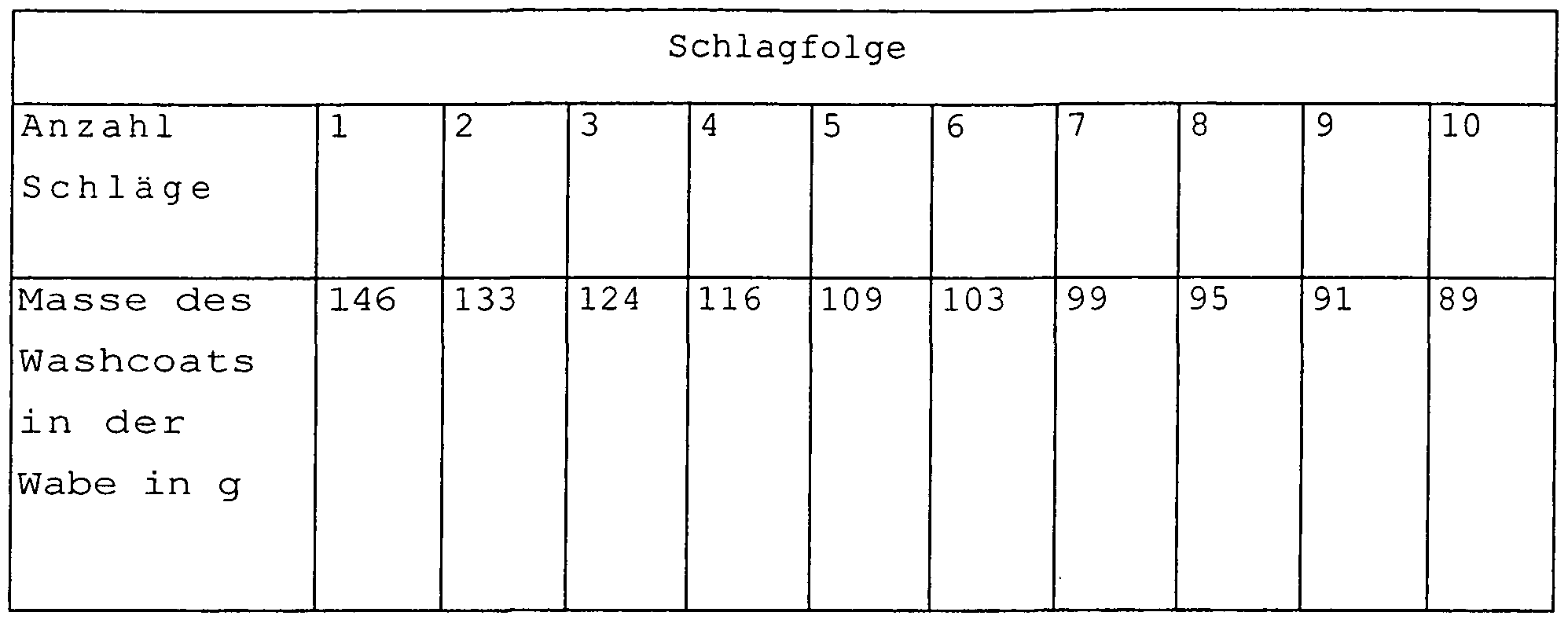
  • Example 3 The experiment described in Example 3 is repeated with the difference that for emptying the unloaded from the piston-cylinder engine partially emptied honeycomb according to Example 2.2 (mass of the contained in the honeycomb washcoat suspension: 161 g) in a 1 m long downspout in a free fall on a Impingement is dropped (as shown in FIG. 3). Due to the rapid deceleration process (impact), there is a further residual emptying of the excess of washcoat suspension from the honeycomb. This process was repeated 9 times (nine times); the results are shown in Table 1.
  • Tab. 1 Remaining amount of remaining washcoat suspension in the honeycomb as a function of the number of impact tests with the downpipe (initially: 161 g washcoat suspension in the honeycomb)
  • Example 5 Coating of a Metallic Carrier Body with a Mixing Function Using a Vibration Unit and Subsequent Emptying in an Acceleration Impact Machine (Vibrator)
  • the apparatus according to FIG. 4 comprises a large oscillating plate (1), which is connected to a frame (3) via four springs (4) arranged at each corner and is set in vibration by means of one or more unbalance motors (5).
  • a further oscillating plate (2) is mounted via a further four springs (6).
  • the purpose of this arrangement is an amplification of the vibration amplitude.
  • a receiving sleeve (8) for receiving the experimental honeycomb (9) attached.
  • the shape of the oscillating plate (2) is chosen (Z-shape) so that the running during operation of the machine washcoat suspension can be collected in a collecting vessel arranged below (7).
  • the receiving sleeve (8) is designed at the lower end (diaphragm ring 10) that the outer wall of the experimental honeycomb (9) rests during braking or the honeycomb can not fall through.
  • the required braking operation is achieved by four Abbremsklotze (11), which are arranged according to the sketch next to the springs (6).
  • the distance of the oscillating plate (2) from the Abbremsklotzen must be smaller than the maximum vibration amplitude (measured without Abbremsklotze) so that there must always come to a "crash" of the plate (2) on the brake pads (11) It is possible to effect a relatively large number of acceleration and deceleration processes within a period of time that makes sense in terms of production (seconds to minutes).
  • the honeycomb After a test duration of 45 seconds, the honeycomb is removed from the receiving device and weighed. After 45 seconds, only 84 g of washcoat suspension is left in the honeycomb. The honeycomb is then dried in a drying oven at 150 0 C and then calcined at 450 0 C for 4 hours. The amount of "dry washcoat” is 44 g, which corresponds to a washcoat amount (dry weight), based on the volume of the honeycomb, of 153 g / l honeycomb.
  • Example 5.2 The experiment described in Example 5.2 is repeated, with the difference that the test honeycomb having a washcoat suspension content of 168 g is introduced into the receiving sleeve (8), but in this case the honeycomb was not firmly fixed.
  • honeycomb Due to the non-fixing of the honeycomb occurs (after the impact on the diaphragm ring (10)) to an additional movement of the honeycomb in the sleeve (deflection height to 5 cm).
  • the motion sequence of the honeycomb differs greatly from that of the vibration plate (the honeycomb moves much slower down).
  • the honeycomb falling relatively frequently hits an upwardly accelerated oscillating plate (2) or the bearing surface (diaphragm ring (10)) connected thereto.
  • the thereby acting on the honeycomb delay and the associated impulse is thus significantly higher than in Example 5.2, which leads to an increase in the emptying effect.
  • the test is ended after 45 seconds and the honeycomb weighed.
  • the honeycomb were only 40 g of toilet suspension available.
  • Example 7 Remaining emptying of a metallic honeycomb body filled with washcoat suspension with a hydraulically operating emptying device according to the impact principle
  • the device according to FIG. 5 was particularly suitable for emptying honeycomb bodies made of metal.
  • the apparatus according to FIG. 5 comprises a compressed air / hydraulic cylinder (1), to whose piston rod a connecting piece (2) is fixedly connected.
  • This connecting piece is connected via a guide rail (3) to a stable frame (up-down).
  • a cylindrical receiving sleeve (6) open at the bottom and at the top, whose bottom end is designed (diaphragm ring), rests against the outer wall of the pilot honeycomb (5) or the honeycomb can not fall through.
  • the receiving sleeve (6) in turn is fixedly connected to the connecting piece (2) via the sleeve holder (7).
  • an impact plate (8) is likewise fastened to the frame (4).
  • the impact plate (8) is designed in such a way that the receiving sleeve, triggered by a downward movement, can strike on the upper side thereof and the washcoat suspension can run down unhindered into a collecting vessel (9).

Abstract

The invention relates to a device and a method for filling a molded article that comprises a plurality of at least partially communicating interior cavities with a liquid phase or for removing the excess of a liquid phase used to coat a molded article comprising interior cavities. The inventive method is characterized in that filling or removal of the excess from the interior cavities is carried out by way of an acceleration process and a subsequent braking process, deceleration being faster than the previous acceleration, with the proviso that the inertial forces caused by deceleration and acting upon the excess liquid phase are higher than the sum of the other opposite forces also acting upon the liquid phase.

Description

Vorrichtung und Verfahren zum Beschichten von Trägern mit ka- talytisch aktiven Materialien Device and method for coating carriers with catalytically active materials
Die Erfindung betrifft eine Vorrichtung und ein Verfahren zur Herstellung von Katalysatoren und deren Verwendung bei der Reinigung von Abgasen.The invention relates to an apparatus and a method for the production of catalysts and their use in the purification of exhaust gases.
Die Erfindung betrifft insbesondere ein Verfahren und eine Vorrichtung zur Herstellung von monolithischen und porösen Katalysatoren durch Auftragung einer Washcoat-Suspension auf ei- nen Kanäle und/oder Poren aufweisenden Formkörper (z.B. Wabenkörper, kurz: Wabe oder Metallschaumkörper) und die Verwendung der so erhaltenen geträgerten Katalysatoren bei der Reinigung von Abgasen von Verbrennungskraftmaschinen.In particular, the invention relates to a method and a device for producing monolithic and porous catalysts by applying a washcoat suspension to moldings (eg honeycomb bodies, in short honeycomb or metal foam body) which have channels and / or pores, and to the use of the supported materials obtained in this way Catalysts in the purification of exhaust gases from internal combustion engines.
Monolithische bzw. poröse Katalysatoren für die Reinigung von Abgasen wie die Oxidation von CO oder Kohlenwasserstoffen zu CO2 und Wasser oder die Reduktion von NOx mit Ammoniak oder Harnstoff zu N2 und Wasser oder die Zersetzung von Harnstoff bzw. dessen thermisches Zersetzungsprodukt, die Isocyansäure, zu Ammoniak und CO2, sind seit langem bekannt. In der Regel sind diese Katalysatoren in der Weise aufgebaut, dass ein mit Kanälen oder Poren durchzogener Formkörper als Trägermaterial dient, der mit einer eine große Oberfläche aufweisenden (hoch- oberflächigen) Metalloxidbeschichtung (Washcoat) , beispielsweise aus Al2O3, SiO2 oder TiO2 überzogen ist und auf diesen metal- loxidischen Oberflächen die eigentlich katalytisch aktiven Metalle oder Metallverbindungen, wie zum Beispiel Edelmetalle oder Übergangsmetalloxide, und gegebenenfalls zusätzliche Promotorverbindungen/Dotierstoffe aufgebracht werden oder schon enthalten sind. Es gibt jedoch auch Anwendungen, bei denen schon die Metall- oxidbeschichtungen allein katalytisch aktiv sind. Ein typisches Anwendungsbeispiel hierfür ist die Hydrolyse von Isocy- ansaure zu Ammoniak an mit TiO2 beschichteten Waben bzw. porösen Formkorpern .Monolithic or porous catalysts for the purification of exhaust gases such as the oxidation of CO or hydrocarbons to CO2 and water or the reduction of NO x with ammonia or urea to N 2 and water or the decomposition of urea or its thermal decomposition product, the isocyanic acid, to ammonia and CO 2 , have long been known. In general, these catalysts are constructed in such a way that a perforated with channels or pores shaped body serves as a carrier material having a high surface area (high surface area) metal oxide coating (washcoat), for example, Al 2 O 3 , SiO 2 or TiO 2 is coated and the actually catalytically active metals or metal compounds, such as precious metals or transition metal oxides, and optionally additional promoter compounds / dopants are applied or already contained on these metal oxide surfaces. However, there are also applications in which even the metal oxide coatings alone are catalytically active. A typical example of this application is the hydrolysis of isocyanic acid to ammonia on TiO 2 coated honeycombs or porous molded articles.
Die Waben bestehen allgemein insgesamt aus einem so genannten Wabenkorper, der sich aus einem Wabenmantel und einem darin eingesetzten Trager, insbesondere einer teilweise strukturierten und aufgewickelten Blechfolie, zusammensetzen kann oder die Wabe besteht insgesamt aus einem keramischen Formkorper. Die Waben sind dabei im Wesentlichen durch parallel zur Achse der Waben verlaufende Kanäle durchzogen. In weiteren, ebenfalls erfindungsgemaß einsetzbaren Weiterbildungen weisen die Waben poröse Kanalwande auf. Die porösen Formkorper bestehen vorzugsweise aus porösen Metall- oder Keramikschaumen, deren Porosität durch das Herstellungsverfahren eingestellt werden kann. Die Herstellung derartiger Metall- oder Keramikschaume erfolgt mittels dem Fachmann an sich bekannter Verfahren.The honeycombs generally generally consist of a so-called honeycomb body, which can be composed of a honeycomb casing and a carrier used therein, in particular a partially structured and wound sheet metal foil, or the honeycomb consists overall of a ceramic shaped body. The honeycombs are essentially traversed by running parallel to the axis of the honeycomb channels. In further embodiments which can likewise be used according to the invention, the honeycombs have porous channel walls. The porous moldings are preferably made of porous metal or ceramic foams, whose porosity can be adjusted by the manufacturing process. The production of such metal or ceramic foam by means of those skilled in per se known method.
Die einen so genannten monolithischen Trager („Wabe") durch- ziehende Kanäle können dabei eine geordnete oder ungeordnete Kanalstruktur besitzen, ferner können die im Wesentlichen parallel verlaufenden Kanäle auch untereinander verbunden sein (so genannte offene Kanalstrukturen) . Bei offenen Kanalstrukturen wird auch eine radiale Gasverteilung innerhalb des Wa- benkorpers (monolithischer Trager) ermöglicht. Die Große der Waben wie auch die Dimensionierung der Kanäle wird dabei vorwiegend von der Dimension der Abgasleitungssysteme der Abgaszusammensetzung und der jeweiligen Anwendung abhangen (DeNOX, DPF, etc.) sowie von den geforderten Druckverlusten und den geforderten Verweilzeiten des Abgases im Katalysator bestimmt. Bei porösen Metall- bzw. Keramikschaumen ist die Porengroßen- Verteilung ein wichtiger Faktor, der durch das Herstellungsverfahren einstellbar ist.The channels running through a so-called monolithic carrier ("honeycomb") can have an ordered or disordered channel structure, furthermore the essentially parallel channels can also be interconnected (so-called open channel structures) The size of the honeycomb as well as the dimensioning of the channels will depend mainly on the dimension of the exhaust gas piping systems of the exhaust gas composition and the respective application (DeNOX, DPF, etc.) as well as the required pressure losses and the required residence times of the exhaust gas in the catalytic converter. For porous metal or ceramic foams, the pore size Distribution is an important factor that can be set by the manufacturing process.
Die so genannte Zelldichte, nämlich die Anzahl der Kanäle pro Wabe bzw. pro Wabenstirnflache bzw. bei Schäumen die Anzahl Poren pro Volumeneinheit, richtet sich ebenfalls nach den An- forderungen. In der Regel liegen diese zwischen 50 und 2000 cpsi (cpsi = cells per Square inch) , also zwischen 50 und 2000 Kanälen pro inch2. In Einzelfallen bzw. für besondere Anwendungen können diese Zelldichten nach unten bzw. oben überschritten werden. Je hoher diese Zelldichte ist, desto hoher ist die für die Reaktion verfugbare Oberflache; in gleicher Weise nimmt aber auch der Druckverlust mit zunehmender Zelldichte zu .The so-called cell density, namely the number of channels per honeycomb or per honeycomb end face or, in the case of foams, the number of pores per unit volume, also depends on the requirements. These are usually between 50 and 2000 cpsi (cpsi = cells per square inch), ie between 50 and 2000 channels per inch 2 . In individual cases or for special applications, these cell densities can be exceeded downwards or upwards. The higher this cell density, the higher the surface available for the reaction; but in the same way the pressure loss increases with increasing cell density.
Als Tragermaterial für Waben aus keramischen Formkorpern finden beispielsweise Materialien wie Cordierit, Steatit, Dura- nit® oder Siliciumcarbid oder Formkorper aus Siliciumdioxid, Aluminiumoxiden, Aluminaten oder auch Metallen und Metallegierungen Verwendung. Die Verwendung von Metallen und Metalllegierungen ermöglicht insbesondere die Herstellung komplex strukturierter Wabenkorper wie beispielsweise Waben mit offe- nen Kanalstrukturen. Poröse Formkorper bestehen vorzugsweise aus Metallen bzw. Legierungen („Metallschaume"), jedoch sind auch die oben erwähnten keramischen Materialien für die Herstellung poröser Formkorper („Keramikschaume") geeignet. Die geometrische Form ist nicht auf eine einzige Form beschrankt, solange 2 im Wesentlichen planparallel zueinander angeordnete Stirnflachen vorhanden sind, jedoch werden typischerweise zylinderförmige Formen bevorzugt.As carrier material for honeycombs made of ceramic molded articles, for example, materials such as cordierite, steatite, Durace® or silicon carbide or shaped bodies of silicon dioxide, aluminum oxides, aluminates or even metals and metal alloys are used. In particular, the use of metals and metal alloys makes it possible to produce complex structured honeycomb bodies such as, for example, honeycombs with open channel structures. Porous moldings are preferably made of metals or alloys ("metal foam"), but also the above-mentioned ceramic materials for the production of porous Formkorper ("ceramic foam") are suitable. The geometric shape is not limited to a single shape as long as there are 2 face planes substantially parallel to each other, but typically cylindrical shapes are preferred.
Die Herstellung eines wie vorstehend beschriebenen Katalysators erfolgt in der Regel durch die Aufbringung eines soge- nannten Washcoats (WC) auf die Kanalwande (Beschichtung) bzw. auf die Porenwände, gefolgt von einer Trocknung mit anschließender Calcinierung bei höheren Temperaturen zur Verfestigung und endgültigen Oberflächengestaltung des Washcoats. Danach werden die katalytisch aktiven Komponenten durch Imprägnierschritte, zumeist aus den wässrigen Lösungen ihrer Vor- laufer auf den Washcoat aufgebracht. Es ist aber auch möglich, die Aktivkomponenten bzw. ihre Vorläuferverbindungen direkt mit dem Beschichtungsprozess aufzubringen.The preparation of a catalyst as described above is generally carried out by the application of a so-called washcoat (WC) on the channel walls (coating) or on the pore walls, followed by drying followed by calcination at higher temperatures to solidify and finalize the washcoat finish. Thereafter, the catalytically active components are applied to the washcoat by impregnation steps, usually from the aqueous solutions of their precursors. But it is also possible to apply the active components or their precursor compounds directly with the coating process.
Die Beschichtung eines Formkörpers mit den anorganischen hoch- oberflächigen Materialien ist durch verschiedene Methoden mög- lieh. In der Regel wird zuerst eine Suspension des anorganischen Trägeroxides in Wasser hergestellt, gegebenenfalls unter Zusatz von Additiven, wie anorganische Binder, Tenside, kata- lytische Aktivkomponenten, Porenbildner, Rheologiehilfsmittel und anderen Zusatzstoffen, und der Formkörper durch einen Tauch-, Saug- oder Pumpprozess mit dieser so genannten Washco- at-Suspension befüllt.The coating of a shaped body with the inorganic highly superficial materials is possible by various methods. As a rule, a suspension of the inorganic carrier oxide in water is first prepared, if appropriate with the addition of additives, such as inorganic binders, surfactants, catalytic active components, pore formers, rheology aids and other additives, and the molding by a dipping, suction or pumping process filled with this so-called washcoat suspension.
Dabei sind Verfahren beschrieben, die nur die exakt berechnete und im Formkörper zu verbleibende Menge an Washcoat-Suspension einbringen und diese Menge möglichst gleichmäßig beispielswei- se auf die Kanalwände bzw. Porenwände verteilen.In this case, methods are described which introduce only the exactly calculated amount of washcoat suspension to be left in the shaped body and distribute this amount as uniformly as possible, for example, to the channel walls or pore walls.
Andere Verfahren geben einen Überschuss in den Formkörper (z.B. Flutung einer Wabe) und führen einen anschließenden Entleerungsvorgang durch, mit dem überschüssige Washcoat- Suspension ausgetragen wird. Oft wird zur Entleerung ein Ausblasen mittels eines Luftstromes durchgeführt.Other processes add excess to the molded article (e.g., flooding of a honeycomb) and then perform a subsequent evacuation process which removes excess washcoat suspension. Often, a purge is carried out by means of an air flow for emptying.
In der DE 19837731 Al sind mehrere dieser Verfahrensvarianten offenbart. Die Entleerung des überschüssigen Washcoats aus einer Wabe mittels einer Zentrifugeneinheit wird beispielsweise im GB 1504060 beschrieben. Die WO 2004/022937 beschreibt ein Verfahren zur Beschichtung von Wabenkorpern durch Einsatz einer Vibrationsanlage, die den zu beschichtenden Wabenkorper Vibrationen aussetzt.In DE 19837731 Al several of these process variants are disclosed. The emptying of the excess washcoat from a honeycomb by means of a centrifuge unit is described for example in GB 1504060. WO 2004/022937 describes a method for coating honeycomb bodies by using a vibration system which exposes the honeycomb body to be coated to vibrations.
Die laufend gestiegenen gesetzlichen Anforderungen bezuglich der Reinigung von Abgasen, insbesondere Motorabgasen, machen die Entwicklung neuer Katalysatoren mit deutlich höheren Effektivitäten notwendig. Neben der Verbesserung der katalyti- schen Beschichtung kann auch durch optimierte Tragermaterialien die Effizienz von Katalysatoren deutlich gesteigert werden.The constantly increasing legal requirements relating to the purification of exhaust gases, in particular engine exhaust gases, make the development of new catalysts with significantly higher efficiencies necessary. In addition to the improvement of the catalytic coating, the efficiency of catalysts can also be significantly increased by optimized carrier materials.
Hierzu gehört einerseits die Erhöhung der Zelldichte aber auch die Verwendung von so genannten komplex strukturierten Wabenbzw, porösen Formkorpern. Unter komplex strukturierten Wabenkorpern versteht man Waben, deren Kanäle Erhebungen oder Vertiefungen oder Schaufeln aufweisen und dadurch im Gasstrom ge- zielt Turbulenzen erzeugt werden, die ebenfalls zu einem besseren Stofftransport und damit höheren Aktivitäten fuhren. Auch offene Strukturen gehören zu dieser Tragerart; bei offenen Strukturen sind - wie oben bereits beschrieben - die Kanäle durch entsprechende Perforationen (Locher, Poren) miteinan- der verbunden. Dadurch ist neben einer vertikalen Stromungsrichtung (parallel zu Kanalachse) auch eine mehr oder weniger horizontale (radial zur Achse der Wabe bzw. der Kanäle) Gas- stromung möglich. Ebenfalls gehören poröse Metallschaume zu den komplexen Strukturen aufgrund der unregelmäßigen Anordnung der Poren. Mit komplexen Strukturen lassen sich Katalysatoren herstellen, die gleichzeitig einen Mischeffekt bewirken. Ferner sind naturlich auch Kombinationen von rein planparallelen und komplexstrukturierten Waben denkbar.This includes, on the one hand, increasing the cell density but also the use of so-called complex-structured honeycomb or porous shaped bodies. Under complex structured honeycomb bodies are meant honeycombs whose channels have elevations or depressions or blades and thus turbulences are specifically generated in the gas stream, which also lead to a better mass transfer and thus higher activities. Open structures are also part of this type of support; In the case of open structures, as already described above, the channels are connected to one another by corresponding perforations (holes, pores). As a result, in addition to a vertical direction of flow (parallel to the channel axis), a more or less horizontal (radially to the axis of the honeycomb or channels) gas flow is possible. Also porous metal foams are among the complex structures due to the irregular arrangement of the pores. With complex structures, it is possible to produce catalysts which simultaneously have a mixing effect. Furthermore, of course, combinations of purely plane-parallel and complex structured honeycomb are conceivable.
Waben und poröse Formkorper mit hohen Zelldichten wie auch Wa- ben mit komplex strukturierten und perforierten Kanälen (offene Strukturen) können durch die bisher bekannten Methoden nicht mehr ohne größeren Aufwand beschichtet werden. Insbesondere das Ausblasen der überschüssigen Washcoat-Suspension mit Luft ist mit offenen Kanalstrukturen bzw. Poren nicht mehr möglich.Honeycombs and porous moldings with high cell densities as well as honeycombs with complex structured and perforated channels (open structures) can be produced by the previously known methods no longer be coated without much effort. In particular, the blowing out of the excess washcoat suspension with air is no longer possible with open channel structures or pores.
Der Grund liegt darin, dass die zum Ausblasen eingesetzte Luft (Ausblasluft) grundsatzlich den Weg des geringsten Widerstandes (Weg des geringsten Druckverlustes) nehmen wird. Sobald zwischen den beiden Stirnflachen der Wabe bzw. der porösen Form- korper einzelne offene Kanäle bzw. Poren entstanden sind, wird die in der Folge eingesetzte Ausblasluft durch die Locher der offenen Strukturen bzw. Poren in eben jene bereits offenen Kanäle bzw. untereinander verbundene Porensystem abgeleitet und der Druck der eingesetzten Ausblasluft wird regelmäßig nicht ausreichen, um die Washcoat-Suspension aus noch teilbefullten Kanälen bzw. Poren, in denen die Washcoat-Suspension durch Ka- pillarkrafte gehalten wird, nach unten auszublasen. Bereits einige wenige vollständig durch Ausblasen entleerte Kanäle bzw. Poren oder Porensysteme fuhren zu dem beschriebenen Effekt, so dass durch Ausblasen allein nur wenige Kanäle oder Teile der Kanäle zu entleeren sind.The reason is that the air used for blowing (blow-out air) will basically take the path of least resistance (least pressure loss path). As soon as individual open channels or pores have been formed between the two end faces of the honeycomb or the porous molded body, the blown-out air used in the sequence will pass through the holes of the open structures or pores into those already open channels or interconnected pore system and the pressure of the blow-out air used is regularly not sufficient to blow down the washcoat suspension from still partially filled channels or pores, in which the washcoat suspension is held by capillary forces. Already a few completely emptied by blowing channels or pores or pore systems lead to the effect described, so that only a few channels or parts of the channels are to be emptied by blowing alone.
Dieser, insbesondere bei Waben mit offenen Strukturen und Me- tallschaumen, zu beobachtende Effekt wird in Fig. 1 veranschaulicht: Fig. 1 zeigt eine Teilansicht zweier parallel verlaufender Kanäle einer Wabe, die über eine Perforation miteinander verbunden sind (offene Struktur) . Wahrend der rechts ge- zeigte Kanal bereits durch die Ausblasluft (die Stromrichtung der Luft wird durch die Pfeile veranschaulicht) von überschüssigem Washcoat befreit wurde, gelingt dies in dem links gezeigten Kanal aus dem beschriebenen Grunde nicht mehr, so dass ein durch Ausblasen alleine nicht mehr zu entfernender und durch die Kapillarkraft gehaltener Rest an Washcoat im unteren Bereich des Kanals verbleibt. Falls der Luftstrom soweit erhöht wird, dass alle Kanäle bzw. Teile der Kanäle frei sind, ist anschließend zu wenig Washcoat auf dem Trager.This effect to be observed, in particular in honeycombs with open structures and metal foams, is illustrated in FIG. 1: FIG. 1 shows a partial view of two parallel channels of a honeycomb which are connected to one another via a perforation (open structure). While the channel shown on the right already has been freed of excess washcoat by the blow-off air (the flow direction of the air is illustrated by the arrows), this is no longer possible in the channel shown on the left for the reason described, so that it is no longer blow-out alone remains to be removed and held by the capillary force remains washcoat in the lower part of the channel. If the air flow increased so far is that all channels or parts of the channels are free, is then too little washcoat on the carrier.
Zur Beschichtung komplex strukturierter Waben und poröser Formkorper sind daher immer aufwandigere Verfahren notwendig. So wird in der DE 10114328 Al beim Auftragen des Washcoats die Anwendung von Vibrationen beschrieben. Damit soll einerseits die Fließfahigkeit der Washcoat-Suspension verbessert werden, andererseits der Wash-coatauftrag möglichst gleichmaßig erfolgen. Aber selbst diese Methoden garantieren nicht mehr die vollständige Entfernung des eingesetzten Überschusses der Washcoat-Suspension, da diese Kraft zu gering ist um diese Kapillarkraft zu überwinden.For coating complex structured honeycombs and porous moldings, therefore, more and more complicated processes are necessary. Thus, the application of vibrations is described in DE 10114328 Al when applying the washcoat. On the one hand, this should improve the flowability of the washcoat suspension, and on the other hand, the washcoat application should be as uniform as possible. But even these methods no longer guarantee complete removal of the excess washcoat suspension used, as this force is too low to overcome this capillary force.
Es bestand somit die Aufgabe, ein Verfahren zur Beschichtung von mit inneren Hohlräumen und/oder Kanälen aufweisenden Form- korpern (z.B. Waben oder Schwammschaumstrukturen) mit offenen und/oder komplexen Hohlraumstrukturen bereit zu stellen, das die genannten Probleme lost. Unter „innerer Hohlraum" werden hier Poren, Locher, Ausnehmungen, oder zumindest partiell untereinander zusammenhangende Poren bzw. Porensysteme verstanden. Typischerweise durchziehen die inneren Hohlräume den ge- samten Formkorper.It is an object of the present invention to provide a process for coating moldings (for example honeycombs or sponge foam structures) having internal cavities and / or channels with open and / or complex cavity structures, which solves the aforementioned problems. By "internal cavity" is meant here pores, holes, recesses, or at least partially interconnected pores or pore systems. [Typ Typ] Typically, the internal cavities pass through the entire shaped body.
Unter „innere Hohlräume" werden vorliegend auch die vorstehend beschriebenen offenen bzw. komplexen Kanalsysteme von Waben verstanden, wie auch Porensysteme von porösen Formkorpern, wie z.B. Metall- und Keramikschaumen .By "internal cavities" is also meant the open and / or complex channel systems of honeycombs described above, as well as porous porous body systems, such as metal and ceramic foams.
Insbesondere bestand die Aufgabe darin, ein Verfahren zur Befreiung bzw. Entleerung von Waben und poröser Formkorper mit offenen und/oder komplexen Strukturen von überschüssig eingesetzter Washcoat-Suspension bereit zu stellen, dass die genannten Probleme lost. Dabei sollte sich die Losung insbesondere durch einfach durchfuhrbare Maßnahmen auszeichnen.In particular, the object was to provide a method for the liberation or emptying of honeycombs and porous moldings with open and / or complex structures of wastecoat used washcoat suspension that solves the above problems. In particular, the solution should be characterized by measures that are easy to implement.
Es wurde nun überraschend gefunden, dass ein sehr gutes Resultat hinsichtlich der Entleerung bzw. der Abtrennung des Überschusses an Washcoat-Suspension in den inneren Hohlräumen und/oder Kanäle eines zu beschichtenden Formkorpers erzielt werden kann, wenn der zu entleerende bzw. zu beschichtende Formkorper sowie die Flüssigkeit einer Zentrifugalkraft ausgesetzt wird. Unter Zentrifugalkraft wird die Kraft verstanden, die auf einen Korper einwirkt, wenn er Beschleunigungs- und/oder Abbremsvorgangen ausgesetzt ist. Eine erfindungsgemaß definierte Zentrifugalkraft kann also z.B. durch Vibrationen nicht erzeugt werden. Bevorzugt wird der Korper und die darin befindliche Flüssigkeit beschleunigt und oder in der Weise abgebremst wird, dass die angewendete Verzögerung dem Betrag nach großer ist als der Betrag der zuvor angewendeten Beschleunigung. Die Verzögerung bzw. das Abbremsen des zu entleerenden bzw. des vom Uberschuss des Washcoats zu befreienden Formkorpers muss also großer sein - letztlich schneller erfolgen - als die zuvor eingesetzte Beschleunigung. Weiter muss die Verzögerung auch so hoch sein, dass die hierbei auftretende Tragheitskraft großer ist, als die zwischen den einzelnen Flussigkeitsschichten des Washcoats wirkenden Kräfte, insbesondere die Kapillar- und Reibungskräfte, die ein Ausfließen des Überschusses verhindern.It has now surprisingly been found that a very good result with regard to the emptying or separation of the excess of washcoat suspension in the inner cavities and / or channels of a molded article to be coated can be achieved if the shaped article to be emptied or coated is also present the liquid is subjected to a centrifugal force. By centrifugal force is meant the force acting on a body when subjected to acceleration and / or deceleration processes. A centrifugal force defined according to the invention can thus e.g. not be generated by vibrations. Preferably, the body and the liquid therein are accelerated and or decelerated in such a way that the applied deceleration is greater in magnitude than the amount of acceleration previously applied. The delay or deceleration of the to be emptied or of the excess of the washcoat to be liberated molded article must therefore be greater - ultimately done faster - than the previously used acceleration. Furthermore, the delay must also be so high that the inertia force occurring in this case is greater than the forces acting between the individual liquid layers of the washcoat, in particular the capillary and frictional forces which prevent the excess from flowing out.
überraschenderweise wurde gefunden, dass die Schichtdicke des aufgebrachten Washcoats mit der Abbremskraft korreliert ist. Je schwacher die Kraft, desto dicker die Schichtdicke und je großer die Kraft, desto dunner die Schichtdicke.Surprisingly, it has been found that the layer thickness of the applied washcoat is correlated with the deceleration force. The weaker the force, the thicker the layer thickness and the greater the force, the thinner the layer thickness.
Nach dem erfindungsgemaßen Verfahren lassen sich beispielswei- se monolithische und auf Metall- bzw. Keramikschaumen basie- rende Katalysatoren, insbesondere so genannte Trageroxid- basierender Katalysatoren, herstellen, die unter anderem als Katalysatoren bei der Reinigung von Abgasen Verwendung finden.According to the process of the invention, for example, monolithic and on metal or ceramic foams based ing catalysts, in particular so-called support oxide-based catalysts, which are used, inter alia, as catalysts in the purification of exhaust gases.
Das erfindungsgemaße Prinzip kann völlig analog auch umgekehrt zur Befüllung eines vorstehend definierten Formkorpers heran- gezogen werden. So lasst sich beispielsweise selbst eine hochviskose Flüssigkeit durch mehrmaliges Beschleunigen und nachfolgendes Abbremsen in enge innere zumindest teilweise miteinander bzw. mit der Oberflache des Formkorpers verbundene Hohlräume oder Kanäle eines Formkorpers einbringen.The principle according to the invention can be used completely analogously, conversely, for filling a shaped body as defined above. Thus, for example, even a highly viscous liquid can be introduced by repeated accelerations and subsequent braking into narrow inner cavities or channels of a shaped body which are at least partially connected to each other or to the surface of the shaped body.
So ist ein weiterer Gegenstand der Erfindung ein Verfahren zur Befüllung eines eine Mehrzahl von inneren Hohlräumen und/oder Kanälen aufweisenden Formkorpers mit einer flussigen Phase, wobei die Befüllung der inneren Hohlräume mit Hilfe eines Beschleunigungsvorganges und einem nachgelagerten Verzogerungs- Vorgang (auch als Abbremsvorgang bezeichnet) erfolgt und wobei die Verzögerung schneller erfolgt als die zuvor erfolgte Beschleunigung, mit der Maßgabe, dass die durch die Verzögerung herbeigeführten und auf die flussige Phase wirkenden Trag- heitskrafte großer sind, als die Summe der sonstigen ebenfalls auf die flussige Phase wirkenden entgegen gerichteten Kräfte.Thus, a further subject of the invention is a method for filling a molded body having a plurality of internal cavities and / or channels with a liquid phase, wherein the filling of the internal cavities takes place with the aid of an acceleration process and a downstream delay operation (also referred to as deceleration process). and wherein the deceleration is faster than the previous acceleration, with the proviso that the gravitational forces induced by the deceleration and acting on the liquid phase are greater than the sum of the other opposing forces also acting on the liquid phase.
Das erfindungsgemaße Prinzip lasst sich grundsätzlich mit jeder flussigen Phase, die sich in den inneren Hohlräumen, wie Kanälen und Poren eines solchen Formkorpers befindet bzw. eingebracht werden soll, einsetzen. Üblicherweise ist die flussige Phase eine Washcoat-Suspension, doch kann die flussige Phase beispielsweise auch Losungen oder dünnflüssige Suspensionen umfassen mit deren Hilfe nachtraglich katalytisch wirksame Substanzen oder Precusorverbindungen auf einen vorbeschichteten Formkorper bzw. Tragerkorper aufgebracht werden. Tragerkor- per, Waben, Wabenkorper und Metallschaum sollen nachstehend als Synonym oder als gleichwirkend mit dem erfindungsgemaß verwendeten Begriff „Formkorper" verstanden werden.The principle according to the invention can basically be used with any liquid phase which is or should be introduced into the internal cavities, such as channels and pores of such a shaped body. Usually, the liquid phase is a washcoat suspension, but the liquid phase can also comprise, for example, solutions or low-viscosity suspensions with the aid of which subsequently catalytically active substances or precursor compounds are applied to a precoated molded body or carrier body. Tragerkor- per, honeycomb, honeycomb body and metal foam are below as Be synonymous or understood as having the same effect as the term "shaped article" used according to the invention.
Vorzugsweise wird das erfindungsgemaße Prinzip zum Aufbringen und Entfernen eines Überschusses einer Washcoat-Suspension verwendet. Im nachfolgenden wird deshalb exemplarisch insbe- sondere auf diese Ausgestaltung des erfindungsgemaßen Verfahrens eingegangen, was jedoch in keiner Weise als Einschränkung zu verstehen ist, da sich das erfindungsgemaße Prinzip in analoger Weise auf samtliche flussige Phasen übertragen lasst.Preferably, the inventive principle for applying and removing an excess of a washcoat suspension is used. In the following, therefore, this embodiment of the method according to the invention will be described by way of example, but this is in no way to be understood as a restriction, since the principle according to the invention can be transferred to all liquid phases in an analogous manner.
Das Prinzip des erfindungsgemaßen Verfahrens beruht darauf, dass durch die Verzögerung ein Impuls auf die in den Kanälen oder Poren befindliche flussige Phase, insbesondere eine überschüssige Washcoat-Suspension, wirkt, wobei dieser Impuls dem Betrag nach großer sein muss als die Summe der sonstigen auf die flussige Phase wirkenden Kräfte, insbesondere die Kapil- lar-und Reibungskräfte.The principle of the method according to the invention is based on the fact that the delay causes an impulse to act on the liquid phase present in the channels or pores, in particular an excess washcoat suspension, this impulse having to be greater in magnitude than the sum of the others liquid phase acting forces, especially the capillary and friction forces.
Die Wirkung des erfindungsgemaßen Befullungs- und Entleerungsprinzips ist dabei nicht an die konkrete Maßnahme zur Durchfuhrung der Beschleunigung oder der Abbremsung bzw. Verzögerung gebunden und prinzipiell völlig unabhängig von deren konkreten Ausgestaltung.The effect of the filling and emptying principle according to the invention is not tied to the specific measure for carrying out the acceleration or deceleration or deceleration and, in principle, completely independent of its concrete design.
In einer Ausfuhrungsform des erfindungsgemaßen Verfahrens kann die Beschleunigung einfach durch die Schwerkraft herbeigeführt werden (beispielsweise den freien Fall eines befullten Form- korpers oder das Gleiten auf einer schrägen Ebene) oder die Beschleunigung wird durch eine auf den Formkorper einwirkende Kraft, beispielsweise eine Federkraft oder eine Kraft resultierend aus einer hydraulischen oder auch pneumatischen Vorrichtung, bewirkt. Die bei der Abbremsung (Verzögerung) auftretende Kraft ist naturgemäß umso großer, je schneller die Abbremsung erfolgt. Die Verzögerung kann im einfachsten Fall durch den Aufprall auf eine entsprechende stehende und fixierte Bremsplatte erfolgen. Es ist aber auch möglich, dass die Abbremsung durch eine sich dem Tragerkorper entgegen bewegende Bremsplatte bewirkt wird. Auf diese Weise wird der zu entleerende Formkorper noch schneller abgebremst, was in der Regel zu einem nochmals verbesserten Entleerungsergebnis fuhrt. Zur Entleerung des Tragerkorpers kann der erfindungsgemaße Entleerungsvorgang (Beschleunigung und anschließende Abbremsung) mehrmals wiederholt werden. Der für eine Entleerung notwendige Kraftimpuls richtet sich nach der Beschaffenheit der flussigen Phase, insbesondere der Wash- coat-Suspension sowie nach der Große der Kapillarkrafte, die innerhalb der inneren Hohlräume wie Poren und Kanäle wirken und von deren Dimensionierung abhangen. So muss die Bremskraft mindestens die Reibung zwischen den Flussigkeitsschichten u- berwmden, um den Erfolg des erfindungsgemaßen Prinzips herbeizufuhren .In one embodiment of the method according to the invention, the acceleration can be brought about simply by gravity (for example the free fall of a filled molded body or sliding on an oblique plane) or the acceleration is effected by a force acting on the shaped body, for example a spring force or a spring force Force resulting from a hydraulic or pneumatic device causes. The force occurring during braking (deceleration) is of course greater, the faster the deceleration takes place. The delay can be done in the simplest case by the impact on a corresponding stationary and fixed brake plate. But it is also possible that the deceleration is effected by a Tragerkorper the counter-moving brake plate. In this way, the body to be emptied is decelerated even faster, which usually leads to a further improved emptying result. To empty the Tragerkorpers the inventive emptying process (acceleration and subsequent deceleration) can be repeated several times. The force impulse required for emptying depends on the nature of the liquid phase, in particular the washcoat suspension and on the size of the capillary forces, which act like pores and channels within the internal cavities and depend on their dimensioning. Thus, the braking force must at least overcome the friction between the fluid layers in order to bring about the success of the principle according to the invention.
Vorzugsweise ist der Betrag der Verzögerung um den Faktor zehn (10) großer als der Betrag der Beschleunigung.Preferably, the amount of delay is ten (10) greater than the amount of acceleration by a factor of ten.
In einer Ausfuhrungsform des erfindungsgemaßen Prinzips, kann die Verzögerung auch in zwei separaten Verzogerungsphasen erfolgen, wobei (vorzugsweise) der Betrag der Verzögerung in der ersten Phase großer ist als der Betrag der Verzögerung in der zweiten Phase.In one embodiment of the inventive principle, the delay can also take place in two separate delay phases, wherein (preferably) the amount of delay in the first phase is greater than the amount of delay in the second phase.
Eine weitere wichtige Einflussgroße ist auch die Temperatur. So ist bekannt, dass die Viskosität einer Flüssigkeit mit steigender Temperatur abnimmt und folglich die Kräfte, die zwischen den Flussigkeitsschichten wirken, abnehmen. Das erfindungsgemaße Entleerungs- und Befullungsprinzip lasst sich durch mechanische Losungen apparativ sehr einfach umsetzen. Dadurch wird die Automatisierung des Entleerungs- bzw. Befullungsprozesses durch das erfindungsgemaße Verfahren deutlich begünstigt.Another important factor is the temperature. Thus, it is known that the viscosity of a liquid decreases with increasing temperature and thus the forces acting between the Flussigkeitsschichten decrease. The emptying and filling principle according to the invention can be implemented very easily by mechanical solutions. As a result, the automation of the emptying or Befullungsprozesses is significantly favored by the inventive method.
Eine Vorrichtung die ebenfalls Gegenstand der vorliegende Erfindung ist und mit der das erfindungsgemaße Verfahren ausgeführt werden kann, umfasst Mittel zur Erzeugung einer auf den Formkorper und die flussige Phase einwirkenden Zentrifugalkraft aufweist. Die Mittel zur Erzeugung einer Zentrifugal- kraft sind insbesondere Mittel zur Beschleunigung und/oder Mittel zum Abbremsen.A device which is also the subject of the present invention and with which the method according to the invention can be carried out, comprises means for producing a centrifugal force acting on the shaped body and the liquid phase. The means for generating a centrifugal force are in particular means for acceleration and / or means for braking.
Eine weitere Vorrichtung, mit der das erfindungsgemaße Verfahren ausgeführt werden kann, ist ein Fallrohr gemäß der Fig. 3. Das Fallrohr umfasst einen senkrecht geführtes, längliches rohrformiges Bauteil, in dem beispielsweise die vom Uberschuss zu befreiende Wabe in den oberen Bereich eingeführt wird, ein Gestell, dass mit dem rohrformigen Bauteil fest verbunden ist, einen Blendenring am unteren Ende des rohrformigen Bauteils, der so gestaltet ist, dass die äußere Wand der Wabe (Wabenhul- Ie) beim Abbremsvorgang aufliegt bzw. die Wabe das rohrformige Bauteil nicht durch deren untere Öffnung verlassen kann (durchfallen kann) , so dass die zu entleerende und durch den freien Fall beschleunigte Wabe abrupt abgebremst wird, sowie ein Auffanggefäß für die abfließende überschüssige flussige Phase. Selbstverständlich gilt das zuvor gesagte auch für die porösen Formkorper, z.B. solche aus Metall- bzw. Keramikschau- men .A further device, with which the method according to the invention can be carried out, is a drop tube according to FIG. 3. The drop tube comprises a vertically guided, elongated tubular component, in which, for example, the honeycomb to be released from the excess is introduced into the upper region Frame that is firmly connected to the rohrformigen component, a diaphragm ring at the lower end of rohrformigen member, which is designed so that the outer wall of the honeycomb (honeycomb Hul- Ie) rests during braking or the honeycomb the rohrformige component not through the lower Opening can leave (can fall through), so that the honeycomb to be emptied and accelerated by the free fall is abruptly braked, and a collecting vessel for the outflowing excess liquid phase. Of course, the foregoing also applies to the porous moldings, e.g. those made of metal or Keramikschau- men.
Beispielhaft erläutert ist eine weitere erfindungsgemaße Vorrichtung, nämlich eine Beschleunigungs-Aufprallvorrichtung mit einem Ruttier gemäß Fig. 4. In Fig. 4 wird ein Kanal aufweisender Formkörper, also z.B. ein Monolith bzw. Wabe, verwendet. Natürlich kann erfindungsgemäß jeder andere vorstehend beschriebene Formkörper ebenfalls verwendet werden. Die Vorrichtung umfasst eine Schwingplatte (1), die über an ihrer Unterseite angebrachte Federn (4) - vorzugsweise vier Federn, die jeweils an den Ecken der Schwingplatte (1) angeordnet sind - mit einem Gestell (3) verbunden ist und mit Hilfe eines oder mehrerer Unwuchtmotoren (5) in Schwingung versetzt werden kann, eine auf der Oberseite der Schwingplatte (1) wiederum über Federn (6) - vorzugsweise wiederum über vier Federn - angebrachte zweite Schwingplatte (2) zur Verstärkung der Schwingungsamplitude, eine im Zentrum der zweiten Schwingplatte (2) angebrachte Aufnahmehülse (8) zur Aufnahme des Wabenkörpers bzw. der Wabe (9), wobei die Form der Schwingplatte (2) so gewählt wird - vorzugsweise eine Z-Form -, dass die beim Betreiben der Vorrichtung ablaufende flüssige Phase, insbesondere die Washcoat-Suspension, in ein darunter angeordnetes Auffanggefäß (7) abfließt und die Aufnahmehülse (8) so gestaltet ist - vorzugsweise mit einem Blendenring (10) -, dass die äußere Wand der Wabe (9) (Wabenhülle) beim Abbremsvorgang aufliegt bzw. die Wabe (9) die Aufnahmehülse (8) nicht durch deren untere Öffnung verlassen kann (durchfallen kann), mehrere Abbremsklötze (11), insbesondere vier Abbremsklötze, die neben den Federn (6) angeordnet sind, wobei der Abstand der Schwingplatte (2) von der oberen Kante der Ab- bremsklötze (11) so gewählt ist, dass dieser kleiner als die maximale Schwingungsamplitude (gemessen ohne Abbremsklötze) ist, so dass es beim Betreiben der Vorrichtung immer zu einem „Aufprall" der Platte (2) auf den Bremsklötzen (11) kommen muss .Illustrated by way of example is a further device according to the invention, namely an acceleration impact device with a rod according to FIG. 4. In Fig. 4, a channel having molding, ie, for example, a monolith or honeycomb, is used. Of course, according to the invention, any other shaped article described above may also be used. The device comprises a swinging plate (1) which is connected to a frame (3) via springs (4) mounted on its underside - preferably four springs respectively arranged at the corners of the swinging plate (1) and with the aid of one or more springs a plurality of unbalance motors (5) can be vibrated, one on the top of the swing plate (1) in turn via springs (6) - preferably in turn via four springs - mounted second swing plate (2) for amplifying the vibration amplitude, one in the center of the second swing plate (2) mounted receiving sleeve (8) for receiving the honeycomb body or the honeycomb (9), wherein the shape of the vibrating plate (2) is selected - preferably a Z-shape - that the running during operation of the device liquid phase, in particular the washcoat suspension, flows into a collecting vessel (7) arranged underneath and the receiving sleeve (8) is designed in such a way - preferably with a diaphragm ring (10) - that the outer wall the honeycomb (9) (honeycomb shell) rests during the braking process or the honeycomb (9) can not leave the receiving sleeve (8) through its lower opening (can fail), several braking pads (11), in particular four braking pads, which are adjacent to the springs ( 6), wherein the distance of the oscillating plate (2) from the upper edge of the Abbremsklötze (11) is chosen so that it is smaller than the maximum oscillation amplitude (measured without Abbremsklötze), so that it always in the operation of the device to an "impact" of the plate (2) on the brake pads (11) must come.
Mit dieser Anordnung ist es möglich, relativ viele Beschleuni- gungs- und Abbremsvorgänge innerhalb eines produktionstechnisch sinnvollen Zeitraums (Sekunden - Minutenbereich) herbeizufüh- ren, vorzugsweise innerhalb von 20-200 Sekunden pro Monolith bzw. Wabe.With this arrangement, it is possible to bring about a relatively large number of acceleration and deceleration processes within a period of time which makes sense in terms of production (seconds-minute range). ren, preferably within 20-200 seconds per monolith or honeycomb.
Die Wabe (9) kann dabei in der Aufnahmehulse (8) fixiert werden oder unfixiert eingebracht werden. Wird die Wabe (9) in der Aufnahmehulse nicht fixiert, kommt es nach dem Aufprall auf dem Blendenring (10) zu einer zusatzlichen (asynchronen) Bewegung der Wabe in der Aufnahmehulse (8) (Auslenkhohe bis zu 10 cm) . Der Bewegungsablauf der Wabe unterscheidet sich dabei stark von dem der Schwingungsplatte, da sich die Wabe wesentlich langsamer nach unten bewegt. Dadurch trifft die herabfal- lende Wabe relativ häufig auf eine nach oben beschleunigte Schwingplatte (2) bzw. den damit verbundenen Blendenring (10). Die dabei auf die Wabe wirkende Verzögerung und der damit verbundene Impuls ist damit deutlich hoher, als im Fall der fixierten Wabe, wodurch es zu einer Verstärkung des Entleerungs- effektes kommt.The honeycomb (9) can be fixed in the receiving sleeve (8) or introduced unfixed. If the honeycomb (9) is not fixed in the receiving sleeve, an additional (asynchronous) movement of the honeycomb in the receiving sleeve (8) (deflection height up to 10 cm) occurs after the impact on the diaphragm ring (10). The movement of the honeycomb differs greatly from that of the vibration plate, as the honeycomb moves much slower down. As a result, the falling honeycomb encounters relatively frequently an upwardly accelerated oscillating plate (2) or the associated diaphragm ring (10). The thereby acting on the honeycomb delay and the associated pulse is thus significantly higher than in the case of the fixed honeycomb, whereby it comes to an increase of the emptying effect.
Eine weitere erfindungsgemaße Vorrichtung, mit der das erfin- dungsgemaße Verfahren ausgeführt werden kann, ist eine hydraulisch oder pneumatisch arbeitende Entleerungsvorrichtung gemäß Fig. 5.A further device according to the invention with which the method according to the invention can be carried out is a hydraulically or pneumatically operated emptying device according to FIG. 5.
Die Vorrichtung gemäß Fig. 5 umfasst einen Pressluft- oder Hydraulikzylinder (1), an dessen Kolbenstange ein Verbindungsstuck (2) fest verbunden ist, wobei das Verbindungsstuck (2) über eine Führungsschiene (3) mit einem stabilen Gestell (4) beweglich (oben - unten) verbunden ist und das Verbindungsstuck (2) weiter mit einer Hulsenhalterung (7) fest verbunden ist, wobei an der Hulsenhalterung (7) zur Aufnahme der Wabe oder des porösen Formkorpers (5) eine nach unten und oben offene zylindrische Aufnahmehulse (6) angebracht ist, deren un- teres Ende so gestaltet ist, vorzugsweise durch einen Blendenring, dass die äußere Wand der Wabe (5) (Wabenhulle) beim Ab- bremsvorgang aufliegt bzw. die Wabe (9) die Aufnahmehulse (6) nicht durch deren untere Öffnung verlassen kann (durchfallen kann) und ein unterhalb der Aufnahmehulse (6) an dem Gestell (4) befestigte Aufprallplatte (8), wobei die AufprallplatteThe device according to FIG. 5 comprises a compressed air cylinder or hydraulic cylinder (1), to the piston rod of which a connecting piece (2) is firmly connected, wherein the connecting piece (2) is movable via a guide rail (3) with a stable frame (4) - Bottom) and the connecting piece (2) is further firmly connected to a Hulsenhalterung (7), wherein on the Hulsenhalterung (7) for receiving the honeycomb or the porous Formkorpers (5) has a downwardly and upwardly open cylindrical Aufnahmehulse (6 ) whose lower end is designed, preferably by a diaphragm ring, that the outer wall of the honeycomb (5) (honeycomb shell) at Ab- brake operation rests or the honeycomb (9) can not leave the Aufnahmehulse (6) through the lower opening (can fall through) and below the Aufnahmehulse (6) on the frame (4) fixed impact plate (8), wherein the impact plate
(8) so gestaltet ist, insbesondere durch eine Öffnung, dass durch ein Aufschlagen der Aufnahmehulse (β) auf die Aufprallplatte (8) die überschüssige flussige Phase, insbesondere die Washcoat-Suspension, nach unten ungehindert in ein Auffanggefäß(8) is designed, in particular by an opening, that by striking the Aufnahmehulse (β) on the impact plate (8) the excess liquid phase, in particular the washcoat suspension, down unhindered in a collecting vessel
(9) ablaufen kann.(9) can expire.
Die Vorrichtung gemäß Fig. 5 eignet sich insbesondere zur Ent- leerung von metallischen Wabenkorpern und poröse Formkorper aus metallischen bzw. keramischen Schäumen.The apparatus according to FIG. 5 is particularly suitable for emptying metallic honeycomb bodies and porous shaped bodies made of metallic or ceramic foams.
Das erfindungsgemaße Verfahren zur Befüllung mit oder zur Entleerung einer flussigen Phase eines innere Hohlräume und/oder Kanäle aufweisenden Formkorpers beruht zusammenfassend darauf, dass der mit Flüssigkeit befullte oder teilbefullte Formkorper zunächst auf eine Geschwindigkeit beschleunigt wird und anschließend wieder stark abgebremst wird, so dass die durch die Verzögerung auf die flussige Phase wirkende Kraft großer ist als Summe der auf die flussige Phase entgegen gesetzt wirkenden Kräfte, insbesondere die Kapillar- und Reibungskräfte bzw. diejenigen Kräfte, die zwischen den Flussigkeitsschichten der in den Kanälen befindlichen flussigen Phase wirken.The inventive method for filling with or for emptying a liquid phase of inner cavities and / or channels having shaped body is based in summary that the liquid filled or teilbefullte shaped body is first accelerated to a speed and then strongly braked again, so that by the delay acting on the liquid phase is greater than the sum of the forces acting on the liquid phase, in particular the capillary and friction forces acting between the liquid layers of the liquid phase in the channels.
In einer weiteren Ausfuhrungsform können die Formkorper auch über alternative Verfahren mit der flussigen Phase, insbeson- dere der Washcoat-Suspension, befullt werden, insbesondere durch Pumpvorgange. Weiter kann auch eine erste Teilentleerung nach einem anderen Funktionsprinzip erfolgen, insbesondere durch Saugen, Ausblasen, Zentrifugieren oder einfaches Ausfließen . In noch einer weiteren Ausfuhrungsform können die vorgenannten Möglichkeiten zur Teilentleerung auch in Kombination mit dem erfindungsgemaßen Entleerungsverfahren eingesetzt werden, insbesondere nacheinander oder zeitgleich.In a further embodiment, the shaped articles can also be filled with the liquid phase, in particular the washcoat suspension, by alternative methods, in particular by pumping. Furthermore, a first partial emptying can be carried out according to another functional principle, in particular by suction, purging, centrifuging or simply flowing out. In yet another embodiment, the abovementioned possibilities for partial emptying can also be used in combination with the emptying method according to the invention, in particular successively or simultaneously.
Das erfindungsgemaße Prinzip zur Entfernung des Überschusses der flussigen Phase, insbesondere der Washcoat-Suspension, kann insbesondere als Teil eines vollständigen Beschichtungs- verfahrens von Kanäle bzw. Poren aufweisenden Formkorpern angewendet werden.The inventive principle for removing the excess of the liquid phase, in particular the washcoat suspension, can be used, in particular, as part of a complete coating process of moldings having channels or pores.
Ein weiterer Gegenstand der Erfindung ist daher auch ein Ver- fahren zur Beschichtung eines eine Mehrzahl von zumindest teilweise miteinander verbundenen inneren Hohlräumen und/oder Kanälen aufweisenden Formkorpers mit einer flussigen Phase umfassend die folgenden SchritteA further subject of the invention is therefore also a method for coating a shaped body having a liquid phase comprising a plurality of at least partially interconnected internal cavities and / or channels, comprising the following steps
A) Ansaugen einer flussigen Phase durch die inneren Hohlräume des zu beschichtenden Formkorpers durch Anlegen eines Unterdruckes auf der oberen Stirnseite des Formkopers, wahrend auf der unteren Stirnseite die flussige Phase zugeführt wird;A) sucking a liquid phase through the inner cavities of the shaped body to be coated by applying a negative pressure on the upper end face of the Formkopers, while on the lower end side of the liquid phase is supplied;
B) Teilentleerung der überschüssigen flussigen Phase aus den inneren Hohlräumen und/oder Kanälen des zu beschichtenden Formkopers mittels Anlegen eines Überdruckes auf der oberen Stirnseite des Wabenkόrpers;B) Partial emptying of the excess liquid phase from the inner cavities and / or channels of the molded copier to be coated by applying an overpressure on the upper end side of the honeycomb body;
C) Entfernen des nach Schritt B) verbleibenden Überschusses an flussiger Phase aus den inneren Hohlräumen und/oder Kanälen des zu beschichtenden Formkopers dadurch gekennzeichnet, dass die Entfernung des Überschusses aus den inneren Hohlräumen mit Hilfe eines Beschleunigungsvorganges und einem nachgelagerten Verzogerungsvorgang (Abbremsvorgang) erfolgt, wobei die Verzögerung schneller erfolgt als die zuvor er- folgte Beschleunigung, mit der Maßgabe, dass die durch die Verzögerung herbeigeführten und auf die überschüssige flussige Phase wirkenden Tragheitskrafte großer sind, als die Summe der sonstigen ebenfalls auf die flussige Phase wirkenden entgegen gerichteten Kräfte.C) removing the excess of liquid phase remaining after step B) from the inner cavities and / or channels of the molded copier to be coated, characterized in that the removal of the excess from the inner cavities takes place by means of an acceleration process and a subsequent delay process (deceleration process), whereby the delay is faster than the previously acceleration followed, with the proviso that the inertia forces produced by the deceleration and acting on the excess liquid phase are greater than the sum of the other opposing forces also acting on the liquid phase.
Die flussige Phase ist dabei vorzugsweise eine Washcoat- Suspension.The liquid phase is preferably a washcoat suspension.
Das Entfernen des nach Schritt B) verbleibenden Überschusses in Schritt C) kann dabei vorzugsweise mit einem Fallrohr gemäß Fig. 3 oder einer der beiden erfindungsgemaßen Vorrichtungen gemäß den Fig. 4 oder 5 erfolgen.The removal of the excess remaining after step B) in step C) can be carried out preferably with a drop tube according to FIG. 3 or one of the two devices according to the invention as shown in FIG. 4 or 5.
Die Teilentfernung des Überschusses gemäß Schritt B) kann auch xn Kombination mit jeder dem Fachmann gelaufigen Methode zur Entleerung von erfindungsgemaß verwendbaren Formkorpern angewendet werden. Vorzugsweise wird die Anwendung eines auf die Kanäle bzw. Poren gerichteten Luftstromes (Ausblasen) und/oder die Anwendung von Zentrifugalkräften eingesetzt.The partial removal of the excess in step B) can also be used in combination with any method known to the person skilled in the art for emptying moldings which can be used according to the invention. Preferably, the application of an air flow directed towards the channels or pores (blowing out) and / or the use of centrifugal forces is used.
Eine Variante des Schrittes B) kann dabei sein, dass die Teilentleerung des Formkorpers ausschließlich durch das Ausfließen der überschüssigen flussigen Phase, insbesondere der Washcoat- Suspension, bedingt durch deren eigene Gewichtskraft erfolgt und dann die Restentleerung durch das erfindungsgemaße Entleerungsverfahren durch Beschleunigung und Abbremsung erfolgt.A variant of step B) may be that the partial emptying of the molded article takes place exclusively by the outflow of the excess liquid phase, in particular the washcoat suspension, due to its own weight and then the emptying is carried out by the emptying process according to the invention by acceleration and deceleration.
In einer bevorzugten Ausfuhrungsform des erfindungsgemaßen Be- schichtungsverfahrens werden die Schritte A) und B) mehrmals hintereinander ausgeführt bevor Schritt C) vorgenommen wird. Insbesondere werden die Schritte A) und B) jeweils dreimal durchlaufen, um sicher zu stellen, dass alle Kanäle bzw. Poren des Formkörpers mit flüssiger Phase, insbesondere mit Washco- at-Suspension mindestens einmal vollständig befüllt waren.In a preferred embodiment of the coating process according to the invention, steps A) and B) are carried out several times in succession before step C) is carried out. In particular, steps A) and B) are each run through three times to ensure that all the channels or pores of the shaped body with liquid phase, in particular with Washco at suspension were filled completely at least once.
Optional kann die Befüllung nach Schritt A) und/oder der Teilentleerungsschritt B) durch Einwirkung von Vibrationen erfolgen, um die Fließeigenschaften der anzusaugenden bzw. auszu- treibenden flüssigen Phase bzw. Washcoat-Suspension zu erhöhen.Optionally, the filling after step A) and / or the partial emptying step B) can be effected by the action of vibrations in order to increase the flow properties of the liquid phase or washcoat suspension to be aspirated or expelled.
Das Befüllen oder Teilbefüllen der Formkörper mit der flüssigen Phase, insbesondere mit der Washcoat-Suspension kann beispielsweise mit einer speziellen Vorrichtung in Form einer Kolbenzylinderanlage erfolgen. Die Vorrichtung ist anhand einer so ge- nannten „Wabe" erläutert, jedoch können natürlich auch entsprechende poröse Metallschäume verwendet werden.The filling or partial filling of the moldings with the liquid phase, in particular with the washcoat suspension, can take place, for example, with a special device in the form of a piston-cylinder system. The device is explained on the basis of a so-called "honeycomb", but of course corresponding porous metal foams can also be used.
Diese Vorrichtung gemäß Fig. 2, umfasst einen KolbenzylinderThis device according to FIG. 2 comprises a piston cylinder
(a) zum Einsaugen bzw. Entleeren der Washcoat-Suspension, eine(a) for sucking in or emptying the washcoat suspension, a
Verbindungsplatte (b) , die mit dem unteren Ende des Kolbenzy- linders fest verbunden ist und mit der oberen Stirnseite der zu beschichtenden Wabe dicht verbunden werden kann, eine Aufnahmeplatte (c) , die auf ihrer Oberseite mit der unteren Stirnseite der zu beschichtenden Wabe dicht verbunden werden kann, optional eine oder mehrere Vibrationseinheiten, die an der Aufnahmeplatte (c) befestigt sind, eine hydraulisch bewegliche Aufhängung (f) mit der die Zylindereinheit (a), die Verbindungsplatte (b) und die Aufnahmeplatte (c) gemeinsam horizontal bewegt werden können (Auf- und Abwärtsbewegung) , ein Einsaug-/ Auslaufrohr (d) , das an der untere Seite der Aufnah- meplatte (c) angebracht ist und eine Vorratswanne (e) , in der die Washcoat-Suspension vorgelegt wird.Connection plate (b), which is firmly connected to the lower end of the Kolbenzy- Linders and can be tightly connected to the upper end of the honeycomb to be coated, a receiving plate (c) on its upper side with the lower end of the honeycomb to be coated tight optionally, one or more vibration units fixed to the receiving plate (c), a hydraulically movable suspension (f) with which the cylinder unit (a), the connecting plate (b) and the receiving plate (c) are moved horizontally together can (up and down movement), an intake / outlet pipe (d), which is attached to the lower side of the receiving plate (c) and a storage trough (e), in which the Washcoat suspension is presented.
Die dichte Verbindung der zu beschichtenden Wabe mit der Verbindungsplatte (b) und der Aufnahmeplatte (c) erfolgt Vorzugs- weise durch Andrucken der Stirnseiten der Waben an entsprechende dichtende Vorrichtungen an den Platten (b) und (c) .The tight connection of the honeycomb to be coated with the connecting plate (b) and the receiving plate (c) is preferred way by pressing the end faces of the honeycomb to corresponding sealing devices on the plates (b) and (c).
Die Verbindungsplatte (b) und die Aufnahmeplatte (c) sind jeweils in dem Bereich, in dem diese die zu befullende Wabe auf¬ nehmen sollen, durchbrochen, so dass einerseits über den KoI- benzylinder (a) ein Druck bzw. Unterdruck aufgebaut werden kann und andererseits durch das Einsaug-/ Auslaufrohr (d) die Wash- coat-Suspension angesaugt bzw. ausgepresst werden kann.The connecting plate (b) and the receiving plate (c) are in each case in the area in which they are to take the honeycomb to be filled ¬ , so that on the one hand on the KoI- benzylinder (a) a pressure or negative pressure can be established and on the other hand, the washcoat suspension can be sucked or pressed out through the suction / discharge pipe (d).
Durch das erfindungsgemaße Beschichtungsverfahren bzw. das er- fmdungsgemaße Entleerungsverfahren lassen sich insbesondere monolithische und auf Metallschaum basierende Katalysatoren, die auf einem im wesentlichen aus TiO2 bestehenden Washcoat basieren, hergestellt werden.The inventive coating method or the emptying method according to the invention make it possible, in particular, to produce monolithic and metal foam-based catalysts which are based on a washcoat consisting essentially of TiO 2 .
Die nach den erfindungsgemaßen Verfahren erhaltlichen Katalysatoren lassen sich insbesondere als Katalysatoren in der Rei- nigung von Abgasen, insbesondere solcher von Verbrennungskraftmaschinen einsetzen.The catalysts obtainable by the processes according to the invention can be used in particular as catalysts in the purification of exhaust gases, in particular those of internal combustion engines.
Mögliche Verwendungen der über das erfindungsgemaße Verfahren erhaltlichen Katalysatoren sind insbesondere die Reinigung von Auto- und Dieselabgasen. Weiter können die nach dem erfin- dungsgemaßen Verfahren hergestellten Katalysatoren als Zersetzungskatalysatoren für Ammoniak-Precusorenverbindungen, als Oxidationskatalysatoren, als Katalysatoren für die Beseitigung von Stickoxiden und als Katalysatoren für die Reduktion von Stickoxiden eingesetzt werden.Possible uses of the catalysts obtainable by the process according to the invention are, in particular, the purification of automobile and diesel exhaust gases. Furthermore, the catalysts prepared by the method according to the invention can be used as decomposition catalysts for ammonia precursor compounds, as oxidation catalysts, as catalysts for the removal of nitrogen oxides and as catalysts for the reduction of nitrogen oxides.
Die erfindungsgemaßen Verfahren können insbesondere zur Herstellung von Katalysatoren eingesetzt werden, bei denen Wash- coat-Suspensionen, bestehend aus Trageroxiden oder Trageroxid- kombmationen, ausgewählt aus der Gruppe enthaltend TiO2, Al2O3, SiO2, CeO2, ZrO2 oder Zeolithe, eingesetzt werden. Die genannten Trageroxide oder Trageroxidkombinationen können dabei wiederum mit Metalloxiden dotiert bzw. beschichtet sein. Auch können bereits direkt katalytisch wirksame Massen oder Massen die direkt zu katalytisch wirksamen Beschichtungen fuhren eingesetzt werden.The novel processes can be used in particular for the preparation of catalysts in which washcoat suspensions consisting of support oxides or support oxide combinations selected from the group comprising TiO 2 , Al 2 O 3 , SiO 2 , CeO 2 , ZrO 2 or zeolites. The mentioned carrier oxides or Trageroxidkombinationen can in turn be doped or coated with metal oxides. Also already directly catalytically active masses or masses can be used directly lead to catalytically active coatings.
Vorzugsweise enthalt die aktive Masse als zusatzliche Komponenten eine oder mehrere Metalloxidverbindungen ausgewählt aus der Gruppe enthaltend die Oxide des Vanadiums, des Wolframs, Molybdäns, insbesondere V2Os, WO3, M0O3 oder Edelmetallsalze, insbesondere die des Palladiums, Platins, Silbers, Rutheniums oder Rhodiums.Preferably, the active composition contains as additional components one or more metal oxide compounds selected from the group comprising the oxides of vanadium, tungsten, molybdenum, in particular V 2 Os, WO 3 , M0O 3 or noble metal salts, in particular those of palladium, platinum, silver, ruthenium or rhodium.
Die katalytisch aktiven Komponenten können aber auch erst in einem nachgelagerten Schritt, nachdem der erfindungsgemaß beschichtete und entleerte Formkorper einer Temperaturbehandlung unterzogen wurde, aufgebracht werden.However, the catalytically active components can also be applied only in a subsequent step after the shaped article which has been coated and emptied according to the invention has been subjected to a temperature treatment.
Die in den erfindungsgemaßen Verfahren einsetzbaren Washcoat- Suspensionen können neben anorganischen Trageroxiden, Wasser, Additive und katalytische Aktivkomponenten enthalten.The washcoat suspensions which can be used in the process according to the invention may contain, in addition to inorganic carrier oxides, water, additives and catalytic active components.
Die anorganischen Trageroxide werden vorzugsweise aus der Grup- pe enthaltend TiO2, Al2O3, SiO2, CeO2, ZrO2 und Zeolithe ausgewählt .The inorganic carrier oxides are preferably selected from the group comprising TiO 2 , Al 2 O 3 , SiO 2 , CeO 2 , ZrO 2 and zeolites.
Den in den erfindungsgemaßen Verfahren eingesetzten Washcoat- Suspensionen können anorganische Sole oder Gele, insbesondere SiO2-, TiO2-, Al2O3-SoIe oder -Gele zur Verbesserung der Haftung der resultierenden Beschichtung, Additive wie organische Mono- und Polymere, insbesondere Cellulose-Derivate oder Acrylate als Porenbildner wie auch als Haftvermittler und/oder Tenside als rheologische Hilfsmittel, zugegeben werden. Für die nach den erfindungsgemaßen Verfahren zu entleerenden bzw. zu beschichtenden Formkorper eignen sich insbesondere Formkorper aus Materialien ausgewählt aus der Gruppe enthaltend Cordierit, Silicate, Zeolithe, Siliciumdioxid, Silicium- carbid, Aluminiumoxid und Aluminate oder Mischungen aus diesen Stoffen sowie Metalle bzw. Metalllegierungen. Besonders bevorzugt sind metallische Tragerstrukturen.The washcoat suspensions used in the process according to the invention can be inorganic sols or gels, in particular SiO 2 , TiO 2 , Al 2 O 3 sols or gels, for improving the adhesion of the resulting coating, additives such as organic mono- and polymers, in particular Cellulose derivatives or acrylates as pore formers as well as adhesion promoters and / or surfactants as rheological aids can be added. Moldings made of materials selected from the group consisting of cordierite, silicates, zeolites, silicon dioxide, silicon carbide, aluminum oxide and aluminates or mixtures of these materials and metals or metal alloys are particularly suitable for the moldings to be emptied or coated by the novel processes. Particularly preferred are metallic support structures.
Bevorzugt sind metallische Tragerkorper, besonders bevorzugt sind komplex strukturierte Metalltrager und Metallschaume.Preference is given to metallic Tragerkorper, particularly preferred are complex structured metal carrier and metal foam.
Weiter können die Tragerstrukturen (Waben) perforierte Kanäle aufweisen, insbesondere wenn es sich um metallische Tragerkorper (Waben) handelt.Furthermore, the carrier structures (honeycombs) can have perforated channels, in particular if they are metallic carrier bodies (honeycombs).
Die verwendeten Metalltrager können dabei durch einen thermischen oder auch chemischen Prozess in der Weise vorbehandelt sein, dass eine spater aufgebrachte Schicht in ihrer Haftung verbessert wird. Mit der erfindungsgemaßen Methode können auch Formkorper mit einer hohen bis sehr hohen Zelldichte entleert werden.The metal carriers used can be pretreated by a thermal or chemical process in such a way that a later applied layer is improved in their adhesion. The method according to the invention can also be used to empty shaped articles having a high to very high cell density.
Die auf diese Weise hergestellten Katalysatoren können noch einen Trocknungsschritt und anschließenden Kalzinierschritt durchlaufen. Auch die weitere Aufbringung von katalytisch aktiven Verbindungen wie beispielsweise Edelmetallverbindungen oder weitere Waschcoats, ist möglich. Die auf diese Weise hergestellten Katalysatoren werden besonders in Gasreinigungspro- zessen, insbesondere bei der Reinigung von Autoabgasen, verwendet. Sie lassen sich aber auch in anderen katalytischen Prozessen einsetzen, wie beispielsweise in der chemischen Industrie oder Energieerzeugung. Das erfindungsgemäße Verfahrensprinzip kann auch zur nachträglichen Aufbringung von katalytischen Substanzen oder Pre- cusorverbindungen, die in Form von Lösungen oder dünnflüssigen Suspensionen auf einen vorbeschichteten Trägerkörper aufgebracht werden sollen, verwendet werden.The catalysts prepared in this way can still undergo a drying step and subsequent calcining step. The further application of catalytically active compounds such as precious metal compounds or other Waschcoats is possible. The catalysts prepared in this way are used especially in gas purification processes, in particular in the purification of automobile exhaust gases. But they can also be used in other catalytic processes, such as in the chemical industry or power generation. The process principle according to the invention can also be used for the subsequent application of catalytic substances or precursor compounds which are to be applied to a precoated carrier body in the form of solutions or low-viscosity suspensions.
Insbesondere lässt sich das erfindungsgemäße Verfahren zur Herstellung von Katalysatoren verwenden, die aus einer metallischen Trägerwabe oder Metall- bzw. Keramikschaum bestehen, die mit einem Washcoat beschichtet sind, wobei der Washcoat aus einem Zeolith und/oder einem oder mehreren Metalloxiden ausgewählt aus der Gruppe enthaltend TiO2, Al2O3, SiO2, CeO2, ZrO2 besteht und als katalytische Aktivkomponenten noch eines oder mehrere Oxide ausgewählt aus der Gruppe enthaltend Vanadium, Wolfram, Molybdän, enthalten ist, wobei solche Katalysatoren zur Reduktion von Stickoxiden in Gegenwart von stickstoffhal- tigen Reduktionsmitteln in der Reinigung von Dieselmotorabgasen verwendet werden.In particular, the process according to the invention can be used for the production of catalysts which consist of a metallic carrier honeycomb or metal or ceramic foam coated with a washcoat, the washcoat comprising a zeolite and / or one or more metal oxides selected from the group TiO 2 , Al 2 O 3 , SiO 2 , CeO 2 , ZrO 2 and as catalytic active components nor one or more oxides selected from the group containing vanadium, tungsten, molybdenum, is contained, such catalysts for the reduction of nitrogen oxides in the presence of nitrogen-containing reducing agents used in the purification of diesel engine exhaust gases.
Weiter lässt sich das erfindungsgemäße Verfahren zur Herstellung von Katalysatoren verwenden, die aus einer metallischen Trägerwabe bzw. Metall- bzw. Keramikschaum bestehen, die mit einem Washcoat beschichtet sind, wobei der Washcoat aus einem oder mehreren Metalloxiden der Gruppe TiO2, Al2O3, SiO2, CeO2, ZrO2 und Zeolithe besteht und wobei diese Katalysatoren zur Zersetzung von Ammoniak-Vorläuferverbindungen in der Reinigung von Dieselmotorabgasen verwendet werden.Furthermore, the process according to the invention can be used for the production of catalysts which consist of a metallic carrier honeycomb or metal or ceramic foam coated with a washcoat, the washcoat consisting of one or more metal oxides of the group TiO 2 , Al 2 O 3 , SiO 2 , CeO 2 , ZrO 2 and zeolites and wherein these catalysts are used to decompose ammonia precursor compounds in the purification of diesel engine exhaust.
Ferner lässt sich das erfindungsgemäße Verfahren zur Herstellung von Katalysatoren verwenden, die aus einer metallischen Trägerwabe bzw. Metall- oder Keramikschaum bestehen, die mit einem Washcoat beschichtet sind, wobei der Washcoat aus einem Zeolith und/oder mehreren Metalloxiden ausgewählt aus der Gruppe enthaltend TiO2, Al2O3, SiO2, CeO2, ZrO2 besteht und als katalytische Aktivkomponenten noch ein oder mehrere Metalle oder Metallverbindungen des Platins, Palladiums, Rhodiums, Silbers und/oder des Rutheniums enthalten ist, wobei solche Katalysatoren zur Oxidation oder Reduktion von Stickoxiden in der Reinigung von Motorverbrennungsabgasen eingesetzt werden.Furthermore, the process according to the invention can be used for producing catalysts which consist of a metallic carrier honeycomb or metal foam or ceramic foam coated with a washcoat, wherein the washcoat consists of a zeolite and / or several metal oxides selected from the group consisting of TiO 2 , Al 2 O 3 , SiO 2 , CeO 2 , ZrO 2 and as catalytic active components nor one or more metals or metal compounds of platinum, palladium, rhodium, silver and / or ruthenium is included, such catalysts are used for the oxidation or reduction of nitrogen oxides in the purification of engine combustion exhaust gases.
Erläuterung der Figuren:Explanation of the figures:
Fig. 1: Illustration des Luftstroms (Pfeile) zum Ausblasen der überschüssigen Washcoat-Suspension in offenen Strukturen. Die Illustration zeigt zwei durch Perforationen miteinander verbundene benachbarte Kanäle als Ausschnitt eines Wabenkörpers. Der Luftstrom folgt bei den perforierten Kanälen dem des geringsten Druckverlustes, wonach in einem solchen Falle durch alleiniges Ausblasen eine Restentleerung aller Kanäle unmöglich wird. Die überschüssige Washcoat-Suspension wird durch die Kapillar-Kräfte in den Kanälen gehalten.1: Illustration of the air flow (arrows) for blowing out the excess washcoat suspension in open structures. The illustration shows two interconnected by channels perforated channels as a section of a honeycomb body. The air flow follows in the case of the perforated channels that of the lowest pressure loss, after which a complete emptying of all channels becomes impossible in such a case by sole blowing. The excess washcoat suspension is held in the channels by the capillary forces.
Fig. 2: Schematische Darstellung einer erfindungsgemäßen Kolbenzylinderanlage .Fig. 2: Schematic representation of a piston cylinder system according to the invention.
Fig. 3: Schematische Darstellung des Aufbaus eines Fallrohrs, insbesondere für die Durchführung der Versuche gemäßFig. 3: Schematic representation of the construction of a downpipe, in particular for carrying out the experiments according to
Beispiel 3.Example 3.
Fig. 4: Schematische Darstellung des Aufbaus einer Beschleuni- gungs-Aufprallvorrichtung umfassend einen Rüttler.4: Schematic representation of the structure of an acceleration impact device comprising a vibrator.
Fig. 5: Schematische Darstellung des Aufbaus einer hydraulisch arbeitenden Entleerungsvorrichtung. Die folgenden Beispiele sollen die Erfindung naher erläutern und sind in keinem Fall als Einschränkung zu betrachten.Fig. 5: Schematic representation of the structure of a hydraulically operating emptying device. The following examples are intended to illustrate the invention in more detail and are in no way to be considered as limiting.
Beispiel 1: Herstellung einer typischen Washcoat-SuspensionExample 1: Preparation of a typical washcoat suspension
100 g TiO2 mit einer BET-Oberflache von 80 m2/g werden in 80 g Wasser eingerührt, anschließend werden 40 g eines wassrigen SiO2-SoIs (Gehalt an SiO2: 40 %) als Binder zugegeben und danach wird die Suspension in einer Zahnrad-Kolloid-Muhle homogenisiert. Die resultierende Washcoat-Suspension hat eine Viskosität von etwa 4100 mpa*s.100 g of TiO 2 with a BET surface area of 80 m 2 / g are stirred into 80 g of water, then 40 g of an aqueous SiO 2 sol (content of SiO 2 : 40%) are added as binder and then the suspension in homogenized with a gear colloid mill. The resulting washcoat suspension has a viscosity of about 4100 mpa * s.
Beispiel 2: Allgemeine Durchfuhrung des ersten Schrittes der Befullung/Teilentleerung einer Metallwabe mit Washcoat- SuspensionExample 2: General implementation of the first step of filling / partial emptying of a metal honeycomb with washcoat suspension
2.1 Beschreibung der Befull- und Teilentleerungsanlage:2.1 Description of the filling and part discharge system:
Der erste Schritt der Befüllung wie auch Teilentleerung der Wa- benkorper wurden mit Hilfe einer Kolbenzylinderanlage gemäß Fig. 2 durchgeführt.The first step of filling as well as partial emptying of the honeycombs were carried out with the aid of a piston-cylinder system according to FIG.
Die Anlage besteht im wesentlichen aus einem Kolbenzylinder (a) zum Einsaugen bzw. Entleeren der Washcoatsuspension, einer Verbindungsplatte (b) , die an dem unteren Ende des Einsaugzylinders fest mit dem Saugzylinder verbunden ist und die in ihrer Unterseite so dimensioniert ist, dass exakt die obere Stirnseite der Wabe mit dem Saugzylinder durch Andrucken einer Aufnahmeplatte (c) dicht verbunden werden kann. Wahlweise können auf der Aufnahmeplatte (c) eine oder mehrere Vibrationseinheiten befestigt werden. Diese Haltevorrichtung (Platten (c) und (b) ) lasst sich gemeinsam mit der Zylindereinheit (a) hydraulisch über die Aufhangung (f) auf und ab bewegen. Auf der Aufnahmeplatte (c) , deren obere Seite so gestaltet ist, dass die untere Stirnseite der Wabe aufgenommen werden kann, ist auf der unteren Seite ein Einsaug-/Auslaufröhr (d) angeflanscht. Ergänzt wird die Versuchsanlage durch eine Vorratswanne (e), in der die Washcoat-Suspension eingefüllt wird.The plant consists essentially of a piston cylinder (a) for sucking or emptying the Washcoatsuspension, a connecting plate (b), which is connected to the lower end of the suction fixed to the suction cylinder and which is dimensioned in its underside so that exactly upper end side of the honeycomb with the suction cylinder by pressing a receiving plate (c) can be tightly connected. Optionally, one or more vibration units can be mounted on the receiving plate (c). This holding device (plates (c) and (b)) can move together with the cylinder unit (a) hydraulically on the suspension (f) up and down. On the receiving plate (c), whose upper side is designed so that the lower end side of the honeycomb can be accommodated, a suction / discharge pipe (d) is flanged on the lower side. The pilot plant is supplemented by a storage tank (e), in which the washcoat suspension is filled.
2.2 Allgemeine Durchfuhrung der Befüllung bzw. Teilentleerung eines Wabenkorpers2.2 General implementation of the filling or partial emptying of a honeycomb body
Die Washcoat-Suspension aus Beispiel 1 wird in der Vorratswanne (e) vorgelegt und zwar mindestens soviel, dass wahrend des spateren Befullvorganges das Einsaugrohr (d) immer vollständig in die Washcoat-Suspension eintaucht. Dann wird die Wabe in die Haltevorrichtung umfassend die Platten (b) und (c) durch hydraulisches Andrucken der Aufnahmeplatte (c) mit Wabe auf dxe Verbindungsplatte (b) dicht eingesetzt und die Kolbenzylindereinheit (a) gemeinsam mit der Haltevorrichtung umfassend die Platten (b) und (c) hydraulisch über die Aufhangung (f) soweit nach unten gefahren, dass das Eintauchrohr (d) in die Washcoat-Suspension eintaucht. Anschließend wird der Zylinder- kolben (a) (ebenfalls hydraulisch) nach oben gefahren, wodurch die Washcoat-Suspension über das Saugrohr (d) in die Wabe ge- saugt wird. Der Kolbenhub wird dabei so eingestellt, dass die Washcoat-Suspension mindestens soweit angesaugt wird, dass die obere Stirnflache der Wabe voll bedeckt ist. Durch ein schnelles Absenken des Kolbens (a) wird ein Großteil der überschüssigen Washcoat-Suspension wieder in die Vorratswanne (e) her- ausgedruckt. Dieser Vorgang wird mindestens 2mal wiederholt, womit sichergestellt ist, dass alle Kanäle mindestens einmal voll befullt (geflutet) waren.The washcoat suspension from Example 1 is initially introduced into the storage trough (e), namely at least so much that during the later filling process the suction pipe (d) is always completely immersed in the washcoat suspension. Then, the honeycomb is tightly inserted into the holding device comprising the plates (b) and (c) by hydraulically pressing the honeycomb receiving plate (c) onto the connecting plate (b), and the piston-cylinder unit (a) together with the holding device comprising the plates (b ) and (c) hydraulically downwards over the suspension (f) so that the immersion tube (d) dips into the washcoat suspension. Then the cylinder piston (a) (also hydraulically) is moved upwards, whereby the washcoat suspension is sucked into the honeycomb via the suction pipe (d). The piston stroke is adjusted so that the Washcoat suspension is at least sucked so far that the upper end face of the honeycomb is completely covered. A quick lowering of the piston (a) causes most of the excess washcoat suspension to be re-printed in the storage pan (e). This process is repeated at least 2 times, ensuring that all channels were full (flooded) at least once.
Zur besseren Befullung/Entleerung der Wabe wird wahrend des gesamten Vorganges der an der Aufnahmeplatte (c) befestigteFor better filling / emptying of the honeycomb is during the entire process attached to the receiving plate (c)
Vibrator in Betrieb genommen ( Druckluftvibrator : Fa. Netter, NFP 18s, Nennfrequenz bei 6 bar= 7700 min-1, Fliehkraft bei β bar= 128 N) , um die Fließeigenschaft der Washcoat-Suspension durch das Anlegen einer Vibrationsfrequenz zusatzlich zu verbessern .Vibrator put into operation (compressed air vibrator: Fa. Netter, NFP improve 18s, rated frequency at 6 bar = 7700 min-1, centrifugal force when the β bar = 128 N), the flow property of the washcoat suspension by applying a frequency of vibration additionally.
Nach mindestens drei Einpump- und Ausdruckvorgangen, wird der Kolben nach dem letzten Ausdruckvorgang mindestens eine Minute lang unten gehalten, wo er verbleibt. Danach wird der Zylinderkolben (a) gemeinsam mit der Haltevorrichtung umfassend die Platten (b) und (c) pneumatisch über die Aufhangung (f) wieder nach oben bewegt, wobei schließlich das Auslaufrohr (d) nicht mehr in die Washcoat-Suspension eintaucht. Die Wabe kann nach entsprechender Druckentlastung (Entspannen der Hydraulik an der Haltevorrichtung) zur weiteren Bearbeitung (Restentleerung) entnommen werden.After at least three pumping and printing operations, the piston is held down for at least one minute after the last printing operation, where it remains. Thereafter, the cylinder piston (a) together with the holding device comprising the plates (b) and (c) pneumatically over the suspension (f) moves back up, and finally the outlet pipe (d) is no longer immersed in the washcoat suspension. The honeycomb can be removed after appropriate pressure relief (relax the hydraulic system on the holding device) for further processing (emptying).
Vergleichsbeispiel 3: Beschichtung eines metallischen Trager- korpers (Wabe) mit Mischerfunktion unter Verwendung einer Vibrationseinheit sowie einer Restentleerung mit einem LuftstromComparative Example 3 Coating of a Metallic Carrier Body (Honeycomb) with a Mixing Function Using a Vibration Unit and Emptying of Remnants with an Air Stream
Eine komplexstrukturierte Metallwabe mit Mischerfunktion (Fa. Emitec, Typ: MI) mit einer Lange von 7,5 cm, einem Durchmesser von 7 cm sowie einer Zelldichte von 200 cpsi wird bei 750°C in einem Kalzinierofen unter Luftatmosphare thermisch 4 h vorbehandelt. Die auf Raumtemperatur abgekühlte Wabe wird dann mittels der unter Beispiel 2.2 beschriebenen Verfahrensweise mit einer nach Beispiel 1 hergestellten Washcoat-Suspension befullt und teilentleert. Danach wirde die Versuchswabe ent- nommen und der enthaltenen Anteil an Washcoat-Suspension durch Wiegen bestimmt. In der Tragerwabe befinden sich 160 g Washcoat-Suspension.A complex-structured metal honeycomb with mixer function (Emitec, type: MI) with a length of 7.5 cm, a diameter of 7 cm and a cell density of 200 cpsi is thermally pretreated at 750 ° C in a calcining furnace under air atmosphere for 4 h. The cooled to room temperature honeycomb is then filled by means of the procedure described in Example 2.2 with a washcoat suspension prepared according to Example 1 and partially emptied. Thereafter, the experimental honeycomb is taken and the content of washcoat suspension contained is determined by weighing. The carrier honeycomb contains 160 g washcoat suspension.
Sofort im Anschluss daran wird durch die Wabe für die Dauer von 1 Min. ein Luftstrom (ca. 200 m3/h) zur Restentleerung durchgeblasen (Ausblasen) und die in der Wabe verbliebene Menge an Washcoat-Suspension erneut durch Wiegen bestimmt. Nach dem Ausblasen befinden sich noch 140 g Washcoat-Suspension in der Wabe. Somit kann durch Ausblasen nur ein geringer Anteil (20 g) des in den Kanälen verbliebenen Überschusses an Washco- at-Suspension ausgetrieben werden.Immediately thereafter, the honeycomb for a period of 1 min. A stream of air (about 200 m 3 / h) for emptying blown through (blowing out) and the amount of washcoat suspension remaining in the honeycomb again determined by weighing. After purging, there are still 140 g washcoat suspension in the honeycomb. Thus, only a small proportion (20 g) of the excess of washcoat suspension remaining in the channels can be expelled by blowing out.
Beispiel 4 : Beschichtung eines metallischen Tragerkorpers mit Mischerfunktion unter Verwendung einer Vibrationseinheit und nachfolgender Restentleerung in einem FallrohrEXAMPLE 4 Coating of a Metallic Carrier Body with a Mixing Function Using a Vibration Unit and Subsequent Remaining Emptying in a Downpipe
Der in Beispiel 3 beschriebene Versuch wird wiederholt mit dem Unterschied, dass zur Restentleerung die aus der Kolbenzylindermaschine entnommene teilentleerte Wabe gemäß Beispiel 2.2 (Masse der in der Wabe enthaltene Washcoat-Suspension: 161 g) in einem 1 m langen Fallrohr im freien Fall auf eine Aufprallblende fallengelassen wird (gemäß Fig. 3) . Bedingt durch den schnellen Abbremsvorgang (Aufprall) kommt es zu einer weiteren Restentleerung des Überschusses an Washcoat-Suspension aus der Wabe. Dieser Vorgang wurde 9x (neunmal) wiederholt; die Ergebnisse sind in Tab. 1 wiedergegeben.The experiment described in Example 3 is repeated with the difference that for emptying the unloaded from the piston-cylinder engine partially emptied honeycomb according to Example 2.2 (mass of the contained in the honeycomb washcoat suspension: 161 g) in a 1 m long downspout in a free fall on a Impingement is dropped (as shown in FIG. 3). Due to the rapid deceleration process (impact), there is a further residual emptying of the excess of washcoat suspension from the honeycomb. This process was repeated 9 times (nine times); the results are shown in Table 1.
Tab. 1: Restmenge an verbleibender Washcoat-Suspension in der Wabe in Abhängigkeit der Anzahl der Aufprall-Versuche mit dem Fallrohr (zu Beginn: 161 g Washcoat-Suspension in der Wabe) Tab. 1: Remaining amount of remaining washcoat suspension in the honeycomb as a function of the number of impact tests with the downpipe (initially: 161 g washcoat suspension in the honeycomb)
Figure imgf000030_0001
Aus den Ergebnissen wird deutlich, dass allein durch diese einfache Verfahrensvariante - Beschleunigung (freier Fall aus 1 m Höhe) und schnelles Abbremsen (Aufprall auf eine Aufnahmeplatte) eine bemerkenswerte Restentleerung erfolgen kann, insbesondere wenn mehrere Fall-Aufprallversuche nacheinander erfolgen. Nach 10 (zehn) aufeinander folgenden Fall-Aufprall- Versuchen ging die Restmenge von 161 g auf 89 g zurück.From the results it becomes clear that a remarkable residual emptying can take place only by this simple process variant - acceleration (free fall from 1 m height) and fast deceleration (impact on a receiving plate), in particular if several case impact tests take place successively. After 10 (ten) consecutive fall-impact tests, the residual amount decreased from 161 g to 89 g.
Beispiel 5: Beschichtung eines metallischen Trägerkörpers mit Mischerfunktion unter Verwendung einer Vibrationseinheit und nachfolgender Restentleerung in einer Beschleunigungs- Aufprallmaschine (Rüttler)Example 5 Coating of a Metallic Carrier Body with a Mixing Function Using a Vibration Unit and Subsequent Emptying in an Acceleration Impact Machine (Vibrator)
5.1 Beschreibung des Entleerungsapparates5.1 Description of the emptying device
Die Apparatur gemäß Fig. 4 umfasst eine große Schwingplatte (1), die über vier jeweils an den Ecken angeordnet Federn (4) mit einem Gestell (3) verbunden ist und mit Hilfe eines oder mehrerer Unwuchtmotoren (5) in Schwingung versetzt wird. Auf der Oberseite der Schwingplatte (1) ist eine weitere Schwingplatte (2) über weitere vier Federn (6) angebracht. Sinn dieser Anordnung ist eine Verstärkung der Schwingungsamplitude. Im Zentrum der Schwingplatte (2) ist eine Aufnahmehülse (8) zur Aufnahme der Versuchswabe (9) angebracht. Die Form der Schwingplatte (2) ist dabei so gewählt (Z-Form), dass die beim Betreiben der Maschine ablaufende Washcoat-Suspension in einem darunter angeordneten Auffanggefäß (7) aufgefangen werden kann. Die Aufnahmehulse (8) ist am unteren Ende so gestaltet (Blendenring 10), dass die äußere Wandung der Versuchswabe (9) beim Abbremsvorgang aufliegt bzw. die Wabe nicht durchfallen kann. Der geforderte Abbremsvorgang wird durch vier Abbremsklotze (11) erreicht, die entsprechend der Skizze neben den Federn (6) angeordnet sind. Der Abstand der Schwingplatte (2) von den Abbremsklotzen muss dabei kleiner als die maximale Schwingungsamplitude (gemessen ohne Abbremsklotze) sein, so dass es immer zu einem „Aufprall" der Platte (2) auf den Bremsklotzen (11) kommen muss. Mit dieser Anordnung ist es möglich, relativ viele Beschleunigungs- und Abbremsvorgange innerhalb eines produktionstechnisch sinnvollen Zeitraumes (Sekunden -Minutenbereich) zu bewirken.The apparatus according to FIG. 4 comprises a large oscillating plate (1), which is connected to a frame (3) via four springs (4) arranged at each corner and is set in vibration by means of one or more unbalance motors (5). On the upper side of the oscillating plate (1), a further oscillating plate (2) is mounted via a further four springs (6). The purpose of this arrangement is an amplification of the vibration amplitude. In the center of the oscillating plate (2) is a receiving sleeve (8) for receiving the experimental honeycomb (9) attached. The shape of the oscillating plate (2) is chosen (Z-shape) so that the running during operation of the machine washcoat suspension can be collected in a collecting vessel arranged below (7). The receiving sleeve (8) is designed at the lower end (diaphragm ring 10) that the outer wall of the experimental honeycomb (9) rests during braking or the honeycomb can not fall through. The required braking operation is achieved by four Abbremsklotze (11), which are arranged according to the sketch next to the springs (6). The distance of the oscillating plate (2) from the Abbremsklotzen must be smaller than the maximum vibration amplitude (measured without Abbremsklotze) so that there must always come to a "crash" of the plate (2) on the brake pads (11) It is possible to effect a relatively large number of acceleration and deceleration processes within a period of time that makes sense in terms of production (seconds to minutes).
5.2 Durchfuhrung des Versuches5.2 Carrying out the experiment
Der im Vergleichsbeispiel 3 beschriebene Versuch wird wiederholt, mit dem Unterschied, dass die Versuchswabe mit einem Ge- halt von 170 g an Washcoat-Suspension in die unter 5.1 oben beschriebene „Entleerungsmaschine" (Ruttier) zur Restentleerung in die Aufnahmehulse (8) fest eingespannt wird. Die Schwingungsplatten (1) und (2) werden durch die Inbetriebnahme der Unwuchtmotoren (5) (Drehzahl 1600 U/min, Unwucht 35 %) in entsprechende Schwingungen versetzt. Der Abstand zwischen der Schwingungsplatte (2) und den Bremsklotzen betragt im ruhenden Zustand 3 mm. Die Schwingungsamplitude der Schwingungsplatte (2) liegt unter diesen Bedingungen bei ca. 15 mm.The experiment described in Comparative Example 3 is repeated, with the difference that the test honeycomb with a content of 170 g of Washcoat suspension firmly clamped in the "emptying machine" (Ruttier) described above under 5.1 for emptying into the Aufnahmehulse (8) The oscillation plates (1) and (2) are set into appropriate vibrations by commissioning the unbalance motors (5) (speed 1600 rpm, imbalance 35%) .The distance between the vibration plate (2) and the brake pads is at rest Condition 3 mm The vibration amplitude of the vibration plate (2) is approximately 15 mm under these conditions.
Nach einer Versuchsdauer von 45 Sek. wird die Wabe aus der Auf- nahmevorrichtung entnommen und gewogen. Nach den 45 Sek. sind nur noch 84 g an Washcoat-Suspension in der Wabe vorhanden. Die Wabe wird anschließend im Trockenschrank bei 1500C getrocknet und im Anschluss daran 4 h lang bei 4500C calciniert. Die Menge an „trockenem Washcoat" beträgt 44 g, was einer Washcoat-Menge (Trockengewicht), bezogen auf das Volumen der Wabe, von 153 g/l Wabe entspricht.After a test duration of 45 seconds, the honeycomb is removed from the receiving device and weighed. After 45 seconds, only 84 g of washcoat suspension is left in the honeycomb. The honeycomb is then dried in a drying oven at 150 0 C and then calcined at 450 0 C for 4 hours. The amount of "dry washcoat" is 44 g, which corresponds to a washcoat amount (dry weight), based on the volume of the honeycomb, of 153 g / l honeycomb.
Beispiel 6: Beschichtung eines metallischen Trägerkörpers mit Mischerfunktion unter Verwendung einer Vibrationseinheit und nachfolgender Restentleerung in einer Beschleunigungs- Aufprallmaschine (Rüttler) mit nicht fixierter WabeEXAMPLE 6 Coating of a Metallic Carrier Body with a Mixing Function Using a Vibration Unit and Subsequent Emptying in an Acceleration Impact Machine (Vibrator) with Unfixed Honeycomb
Der im Beispiel 5.2 beschriebene Versuch wird wiederholt, mit dem Unterschied, dass die Versuchswabe mit einem Washcoat- Suspensionsgehalt von 168 g in die Aufnahmehülse (8) eingebracht wird, in diesem Fall aber die Wabe nicht fest fixiert war.The experiment described in Example 5.2 is repeated, with the difference that the test honeycomb having a washcoat suspension content of 168 g is introduced into the receiving sleeve (8), but in this case the honeycomb was not firmly fixed.
Durch die Nichtfixierung der Wabe kommt es (nach dem Aufprall auf dem Blendenring (10)) zu einer zusätzlichen Bewegung der Wabe in der Hülse (Auslenkhöhe bis 5 cm) . Der Bewegungsablauf der Wabe unterscheidet sich dabei stark von dem der Schwingungsplatte (die Wabe bewegt sich wesentlich langsamer nach unten) . Dadurch trifft die herab fallende Wabe relativ häufig auf eine nach oben beschleunigte Schwingplatte (2) bzw. die damit verbundene Auflagefläche (Blendenring (10) ) . Die dabei auf die Wabe wirkende Verzögerung und der damit verbundene Impuls ist damit deutlich höher, als im Beispiel 5.2, wodurch es zu einer Verstärkung des Entleerungseffektes kommt.Due to the non-fixing of the honeycomb occurs (after the impact on the diaphragm ring (10)) to an additional movement of the honeycomb in the sleeve (deflection height to 5 cm). The motion sequence of the honeycomb differs greatly from that of the vibration plate (the honeycomb moves much slower down). As a result, the honeycomb falling relatively frequently hits an upwardly accelerated oscillating plate (2) or the bearing surface (diaphragm ring (10)) connected thereto. The thereby acting on the honeycomb delay and the associated impulse is thus significantly higher than in Example 5.2, which leads to an increase in the emptying effect.
Bei der gleichen Einstellung der Parameter wie in Beispiel 5.2 wird der Versuch nach 45 Sek. beendet und die Wabe gewogen. In der Wabe waren nur noch 40 g WC-Suspension vorhanden. Somit zeigt sich, dass durch die Entkopplung der Bewegung von Auf- nahmeplatte und Wabe (= Aufwartsbewegung der Platte und Abwartsbewegung der Wabe) der bei Aufprall resultierende Abbremsimpuls deutlich erhöht werden und auf diese Weise eine sehr effektive Restentleerung der Wabe herbeigeführt werden kann.At the same setting of the parameters as in example 5.2, the test is ended after 45 seconds and the honeycomb weighed. In the honeycomb were only 40 g of toilet suspension available. Thus, it can be seen that by decoupling the movement of acquisition plate and honeycomb (= upward movement of the plate and Abwartsbewegung the honeycomb) resulting in impact deceleration impulse can be significantly increased and in this way a very effective emptying of the honeycomb can be brought about.
Beispiel 7 : Restentleerung eines mit Washcoat-Suspension be- fullten metallischen Wabenkorpers mit einer hydraulisch arbeitenden Entleerungsvorrichtung nach dem AufprallprinzipExample 7: Remaining emptying of a metallic honeycomb body filled with washcoat suspension with a hydraulically operating emptying device according to the impact principle
7.1 Hydraulisch arbeitende Entleerungsvorrichtung7.1 Hydraulic discharge device
Die Vorrichtung gemäß Fig. 5 eignete sich besonders zur Entlee- rung von Wabenkorpern aus Metall.The device according to FIG. 5 was particularly suitable for emptying honeycomb bodies made of metal.
Die Apparatur gemäß Fig. 5 umfasst einen Pressluft/Hydraulikzylinder (1), an dessen Kolbenstange ein Verbindungsstuck (2) fest verbunden ist. Dieses Verbindungsstuck ist über eine Führungsschiene (3) mit einem stabilen Gestell be- weglich (oben - unten) verbunden. Zur Aufnahme der Versuchswabe dient eine nach unten und oben offene zylindrische Aufnah- mehulse (6), dessen unteres Ende so gestaltet ist (Blendenring), dass die äußere Wandung der Versuchswabe (5) aufliegt bzw. die Wabe nicht durchfallen kann. Die Aufnahmehulse (6) wiederum ist über die Hulsenhalterung (7) mit dem Verbindungsstuck (2) fest verbunden. Unterhalb der Aufnahmehulse (6) ist ebenfalls an dem Gestell (4) eine Aufprallplatte (8) befestigt. Die Aufprallplatte (8) ist dabei so gestaltet, dass auf deren oberer Seite die Aufnahmehulse, ausgelost durch eine Ab- wartsbewegung, aufschlagen kann und dabei die Washcoat- Suspension nach unten ungehindert in ein Auffanggefäß (9) ablaufen kann . The apparatus according to FIG. 5 comprises a compressed air / hydraulic cylinder (1), to whose piston rod a connecting piece (2) is fixedly connected. This connecting piece is connected via a guide rail (3) to a stable frame (up-down). To receive the experimental honeycomb, a cylindrical receiving sleeve (6), open at the bottom and at the top, whose bottom end is designed (diaphragm ring), rests against the outer wall of the pilot honeycomb (5) or the honeycomb can not fall through. The receiving sleeve (6) in turn is fixedly connected to the connecting piece (2) via the sleeve holder (7). Below the receiving sleeve (6), an impact plate (8) is likewise fastened to the frame (4). The impact plate (8) is designed in such a way that the receiving sleeve, triggered by a downward movement, can strike on the upper side thereof and the washcoat suspension can run down unhindered into a collecting vessel (9).

Claims

Patentansprüche claims
1. Vorrichtung zum Befullen eines Formkorpers (9) mit einer flussigen Phase und zur Entfernung einer flussigen Phase aus einem Formkorper (9), wobei der Formkorper (9) eine Vielzahl innerer Hohlräume und/oder Kanäle aufweist, dadurch gekennzeichnet, dass die Vorrichtung Mittel zur Erzeugung einer auf den Formkorper (9) und die flussige Phase einwirkenden Zentrifugalkraft aufweist.Device for filling a shaped body (9) with a liquid phase and for removing a liquid phase from a shaped body (9), the shaped body (9) having a multiplicity of internal cavities and / or channels, characterized in that the device comprises means for generating a force acting on the Formkorper (9) and the liquid phase centrifugal force.
2. Vorrichtung nach Anspruch 1, dadurch gekennzeichnet, dass die Mittel zur Erzeugung einer Zentrifugalkraft, Mittel zur Beschleunigung und/oder Mittel zum Abbremsen sind.2. Apparatus according to claim 1, characterized in that the means for generating a centrifugal force, acceleration means and / or braking means are.
3. Vorrichtung nach Anspruch 1 und 2, dadurch gekennzeichnet, dass die Mittel zur Beschleunigung eine erste Schwingplatte (1) umfassen, die über an ihrer Unterseite angebrachte Federn (4) mit einem Gestell (3) verbunden ist und eine zur Verstärkung der Schwingungsamplitude der ersten Schwingplatte (1) auf der Oberseite der ersten Schwingplatte (1) über Federn (6) angebrachte zweite Schwingplatte (2), und wobei die Mittel zum Abbremsen eine im Zentrum der zweiten Schwingplatte (2) angebrachte Auf- nahmehulse (8) zur Aufnahme des Formkorpers (9) umfassen.3. Device according to claim 1 and 2, characterized in that the means for acceleration comprise a first oscillating plate (1) which is connected via mounted on its underside springs (4) with a frame (3) and one for amplifying the oscillation amplitude of first oscillating plate (1) on the upper side of the first oscillating plate (1) via springs (6) mounted second oscillating plate (2), and wherein the means for decelerating in the center of the second oscillating plate (2) mounted receiving sleeve (8) for receiving of the shaped body (9).
4. Vorrichtung nach Anspruch 3, weiter umfassend eine Mehrzahl von Abbremsklotzen (11), die neben den Federn (6) angeordnet sind, wobei der Abstand der Schwingplatte (2) vom oberen Ende der Abbremsklotze (11) so gewählt wird, dass dieser kleiner als die maximale kombinierte Schwin- gungsamplitude der Schwingplatten (1), (2) ist. 4. Apparatus according to claim 3, further comprising a plurality of Abbremsklotzen (11), which are arranged next to the springs (6), wherein the distance of the oscillating plate (2) from the upper end of the Abbremsklotze (11) is selected so that this smaller is the maximum combined vibration amplitude of the vibrating plates (1), (2).
5. Vorrichtung nach Anspruch 4, dadurch gekennzeichnet, dass jede der an der Unterseite der Schwingplatte (1) angebrachten Feder (4) an je einer Ecke der Schwingplatte (1) angeordnet ist.5. Apparatus according to claim 4, characterized in that each of the underside of the oscillating plate (1) mounted spring (4) is arranged at each corner of the vibrating plate (1).
6. Vorrichtung nach Anspruch 4 oder 5, dadurch gekennzeichnet, dass die Schwingplatte (2) eine Z-Form aufweist .6. Apparatus according to claim 4 or 5, characterized in that the oscillating plate (2) has a Z-shape.
7. Vorrichtung nach einem der vorhergehenden Ansprüche, dadurch gekennzeichnet, dass die Aufnahmehulse (8) mit einem Blendenring (10) versehen ist.7. Device according to one of the preceding claims, characterized in that the Aufnahmehulse (8) is provided with a diaphragm ring (10).
8. Vorrichtung nach Anspruch 1 und 2, wobei die Mittel zur Beschleunigung einen Pressluft- oder Hydraulikzylinder8. Apparatus according to claim 1 and 2, wherein the means for accelerating a compressed air or hydraulic cylinder
(1) umfassen, an dessen Kolbenstange ein Verbindungsstuck(1), on whose piston rod a connecting piece
(2) fest verbunden ist, wobei das Verbindungsstuck (2) über eine Führungsschiene (3) mit einem stabilen Gestell (4) beweglich verbunden ist und das Verbindungsstuck (2) weiter mit einer Hulsenhalterung (7) fest verbunden ist, wobei an der Hulsenhalterung (7) zur Aufnahme des Form- korpers (5) eine nach unten und oben offene zylindrische Aufnahmehulse (6) angebracht ist, deren unteres Ende so ausgestaltet ist, dass die äußere Wand des Formkorpers(2) is fixedly connected, wherein the connecting piece (2) via a guide rail (3) with a stable frame (4) is movably connected and the connecting piece (2) is further firmly connected to a Hulsenhalterung (7), wherein at the Hulsenhalterung (7) for receiving the molded body (5) has a downwardly and upwardly open cylindrical Aufnahmehulse (6) is mounted, whose lower end is designed so that the outer wall of the molded article
(5) bei einem Abbremsvorgang die Aufnahmehulse (6) nicht durch deren untere Öffnung verlassen kann und das Mittel zum Abbremsen eine unterhalb der Aufnahmehulse (6) an dem(5) can not leave the Aufnahmehulse (6) through the lower opening during a deceleration and the means for braking a below the Aufnahmehulse (6) on the
Gestell (4) befestigte Aufprallplatte (8) ist.Frame (4) mounted impact plate (8).
9. Verfahren zum Befullen eines Formkorpers mit einer flussigen Phase oder zum Entfernen eines Überschusses einer flussigen Phase, wobei der Formkorper eine Vielzahl innerer Hohlräume und/oder Kanäle aufweist, umfassend den Schritt des Einwirkenlassens einer Zentrifugalkraft auf den mit der flüssigen Phase in einem ersten Schritt befüllten Formkörper und die flüssige Phase, wobei die einwirkende Zentrifugalkraft größer ist, als die Summe der sonstigen ebenfalls auf die flüssige Phase wirkenden entgegen gerichteten Kräfte.9. A method of filling a mold with a liquid phase or removing an excess of a liquid phase, the mold having a plurality of internal cavities and / or channels, comprising the step of applying a centrifugal force the filled with the liquid phase in a first step molding and the liquid phase, wherein the centrifugal force acting is greater than the sum of the other also acting on the liquid phase oppositely directed forces.
10. Verfahren nach Anspruch 9, wobei die Zentrifugalkraft eine Kraft ist, die durch Beschleunigung und/oder Abbremsen des Formkörpers und der flüssigen Phase hervorgerufen wird.10. The method of claim 9, wherein the centrifugal force is a force caused by acceleration and / or deceleration of the shaped body and the liquid phase.
11. Verfahren nach Anspruch 10, wobei der befüllte Formkörper auf eine Geschwindigkeit von mindestens 0,5 m/s beschleu- nigt und anschließend abrupt in den Ruhezustand abgebremst wird .11. The method of claim 10, wherein the filled shaped body accelerates to a speed of at least 0.5 m / s and then abruptly braked to the resting state.
12. Verfahren nach einem der vorhergehenden Ansprüche, wobei der erste Schritt des Befüllens umfasst:12. The method according to any one of the preceding claims, wherein the first step of filling comprises:
A) das Ansaugen einer flüssigen Phase durch die inneren Hohlräume und/oder Kanäle des zu beschichtenden Formkörpers durch Anlegen eines Unterdruckes auf der oberen Stirnseite des Formköpers, während auf der unteren Stirnseite die flüssige Phase zugeführt wird;A) the suction of a liquid phase through the inner cavities and / or channels of the molded body to be coated by applying a negative pressure on the upper end face of the molded body, while on the lower end side, the liquid phase is supplied;
B) die Teilentleerung der überschüssigen flüssigen Phase aus den inneren Hohlräumen und/oder Kanälen des Formköpers mittels Anlegen eines Überdruckes auf der oberen Stirnfläche des Formkörpers.B) the partial emptying of the excess liquid phase from the inner cavities and / or channels of the molded body by applying an overpressure on the upper end face of the shaped body.
13. Verfahren nach einem der vorhergehenden Ansprüche, dadurch gekennzeichnet, dass die flüssige Phase eine Suspension, Lösung, Aufschlämmung oder Dispersion ist. 13. The method according to any one of the preceding claims, characterized in that the liquid phase is a suspension, solution, slurry or dispersion.
PCT/EP2006/005000 2005-05-25 2006-05-24 Device and method for coating substrates with catalytically active materials WO2006125648A2 (en)

Priority Applications (3)

Application Number Priority Date Filing Date Title
US11/915,369 US20080182020A1 (en) 2005-05-25 2006-05-24 Device and Method For Coating Substrates With Catalytically Active Materials
CA002605285A CA2605285A1 (en) 2005-05-25 2006-05-24 Device and method for coating substrates with catalytically active materials
EP06753869A EP1885494A2 (en) 2005-05-25 2006-05-24 Device and method for coating substrates with catalytically active materials

Applications Claiming Priority (2)

Application Number Priority Date Filing Date Title
DE102005024108A DE102005024108A1 (en) 2005-05-25 2005-05-25 Process and apparatus for the preparation of catalysts and their use in the purification of exhaust gases
DE102005024108.5 2005-05-25

Publications (2)

Publication Number Publication Date
WO2006125648A2 true WO2006125648A2 (en) 2006-11-30
WO2006125648A3 WO2006125648A3 (en) 2007-03-15

Family

ID=36658643

Family Applications (1)

Application Number Title Priority Date Filing Date
PCT/EP2006/005000 WO2006125648A2 (en) 2005-05-25 2006-05-24 Device and method for coating substrates with catalytically active materials

Country Status (5)

Country Link
US (1) US20080182020A1 (en)
EP (1) EP1885494A2 (en)
CA (1) CA2605285A1 (en)
DE (1) DE102005024108A1 (en)
WO (1) WO2006125648A2 (en)

Cited By (2)

* Cited by examiner, † Cited by third party
Publication number Priority date Publication date Assignee Title
EP2172266A1 (en) 2008-09-12 2010-04-07 Süd-Chemie Ag Urea hydrolysis catalyst
DE102008061644A1 (en) 2008-12-12 2010-06-24 Fraunhofer-Gesellschaft zur Förderung der angewandten Forschung e.V. Cellular material for high temperature applications and process for its preparation

Families Citing this family (5)

* Cited by examiner, † Cited by third party
Publication number Priority date Publication date Assignee Title
FR2916656B1 (en) * 2007-05-30 2011-05-13 Peugeot Citroen Automobiles Sa CATALYTIC MONOLITH FOR EXHAUST GASES FROM AN INTERNAL COMBUSTION ENGINE
DE102007048313B4 (en) * 2007-10-09 2011-07-28 Süd-Chemie AG, 80333 Coating of substrates while ensuring a high porosity with high abrasion resistance of the coating
DE102008016177A1 (en) * 2008-03-28 2009-10-08 Süd-Chemie AG Harnstoffhydrolysekatalysator
US8263032B2 (en) * 2010-02-01 2012-09-11 Johnson Matthey Public Limited Company Oxidation catalyst
CN113393979A (en) * 2021-06-09 2021-09-14 天津精达里亚特种漆包线有限公司 Enameled wire oil film coating structure, coating method and detection method after coating

Citations (11)

* Cited by examiner, † Cited by third party
Publication number Priority date Publication date Assignee Title
DE2539764A1 (en) * 1974-09-10 1976-04-15 Air Prod & Chem METHOD OF COATING A HEAT-RESISTANT CARRIER MATERIAL WITH AN ACTIVE METAL OXIDE FILM
US4039482A (en) * 1974-10-21 1977-08-02 Universal Oil Products Company Method of coating and impregnating catalyst support members
US4208454A (en) * 1978-01-19 1980-06-17 General Motors Corporation Method for coating catalyst supports
WO1997048500A1 (en) * 1996-06-21 1997-12-24 Engelhard Corporation Method for coating a substrate
US5953832A (en) * 1998-04-28 1999-09-21 Engelhard Corporation Method for drying a coated substrate
US20010024686A1 (en) * 2000-03-23 2001-09-27 Ralph Kiessling Method for partially coating a carrier body
US6478874B1 (en) * 1999-08-06 2002-11-12 Engelhard Corporation System for catalytic coating of a substrate
US20030044520A1 (en) * 2001-06-30 2003-03-06 Omg Ag & Co. Kg Process for coating a carrier structure
US20050076505A1 (en) * 2003-10-08 2005-04-14 Esw Technologies, Inc. Fused porous catalytic element
WO2005084807A1 (en) * 2004-02-24 2005-09-15 Advanced Technology Products, Inc. Method and apparatus for the removal of excess coating material form a honeycomb body
EP1580288A1 (en) * 2002-11-20 2005-09-28 Nippon Steel Corporation HIGH-Al STAINLESS STEEL PLATE AND DOUBLE-LAYERED PLATE, PROCESS FOR PRODUCING THE SAME, A HONEYCOMB STRUCTURE THEREFROM AND PROCESS FOR PRODUCING THE HONEYCOMB STRUCTURE

Patent Citations (11)

* Cited by examiner, † Cited by third party
Publication number Priority date Publication date Assignee Title
DE2539764A1 (en) * 1974-09-10 1976-04-15 Air Prod & Chem METHOD OF COATING A HEAT-RESISTANT CARRIER MATERIAL WITH AN ACTIVE METAL OXIDE FILM
US4039482A (en) * 1974-10-21 1977-08-02 Universal Oil Products Company Method of coating and impregnating catalyst support members
US4208454A (en) * 1978-01-19 1980-06-17 General Motors Corporation Method for coating catalyst supports
WO1997048500A1 (en) * 1996-06-21 1997-12-24 Engelhard Corporation Method for coating a substrate
US5953832A (en) * 1998-04-28 1999-09-21 Engelhard Corporation Method for drying a coated substrate
US6478874B1 (en) * 1999-08-06 2002-11-12 Engelhard Corporation System for catalytic coating of a substrate
US20010024686A1 (en) * 2000-03-23 2001-09-27 Ralph Kiessling Method for partially coating a carrier body
US20030044520A1 (en) * 2001-06-30 2003-03-06 Omg Ag & Co. Kg Process for coating a carrier structure
EP1580288A1 (en) * 2002-11-20 2005-09-28 Nippon Steel Corporation HIGH-Al STAINLESS STEEL PLATE AND DOUBLE-LAYERED PLATE, PROCESS FOR PRODUCING THE SAME, A HONEYCOMB STRUCTURE THEREFROM AND PROCESS FOR PRODUCING THE HONEYCOMB STRUCTURE
US20050076505A1 (en) * 2003-10-08 2005-04-14 Esw Technologies, Inc. Fused porous catalytic element
WO2005084807A1 (en) * 2004-02-24 2005-09-15 Advanced Technology Products, Inc. Method and apparatus for the removal of excess coating material form a honeycomb body

Cited By (3)

* Cited by examiner, † Cited by third party
Publication number Priority date Publication date Assignee Title
EP2172266A1 (en) 2008-09-12 2010-04-07 Süd-Chemie Ag Urea hydrolysis catalyst
DE102008046994A1 (en) 2008-09-12 2010-06-02 Süd-Chemie AG Urea hydrolysis catalyst
DE102008061644A1 (en) 2008-12-12 2010-06-24 Fraunhofer-Gesellschaft zur Förderung der angewandten Forschung e.V. Cellular material for high temperature applications and process for its preparation

Also Published As

Publication number Publication date
WO2006125648A3 (en) 2007-03-15
CA2605285A1 (en) 2006-11-30
EP1885494A2 (en) 2008-02-13
US20080182020A1 (en) 2008-07-31
DE102005024108A1 (en) 2006-11-30

Similar Documents

Publication Publication Date Title
WO2006125649A2 (en) Method and device for applying washcoat suspensions to a molded article
WO2006125648A2 (en) Device and method for coating substrates with catalytically active materials
DE60319756T2 (en) Honeycomb filter for exhaust gas purification, adhesive, coating material and method for producing such a honeycomb filter body
EP1789190B1 (en) Method for coating a wall flow filter with a coating composition
DE102008055890A1 (en) Particulate reduction with combined SCR and NH3 slip catalyst
DE102014215112A1 (en) Process for preparing a catalyst and catalyst articles
DE112014000588T5 (en) Ammonia oxidation catalyst
EP2414079A1 (en) Age-resistant catalyst for oxidation of no to no2 in exhaust streams de gaz d'échappement
EP1594587B1 (en) Method for removing dirt and/or clogged material from a set of ducts
EP1634646A1 (en) Process for producing exhaust gas purification means and purification means
DE202010018032U1 (en) Honeycomb filter
DE102005054946B4 (en) Process for coating or impregnating the surfaces of a catalyst support
EP3648884A1 (en) Contactless leveling of a washcoat suspension
WO2012156503A1 (en) Low-temperature oxidation catalyst with particularly marked hydrophobic properties for the oxidation of organic pollutants
DE102006027700A1 (en) Device for filling a form body with wash coat suspension and for removing the suspension from the body for purification of exhaust gas from internal combustion engine, comprises unit for generating centrifugal force, and acceleration unit
DE102006027701A1 (en) Removing excess liquid from a molded body with two frontal planar surface, inner cavity and channel comprises introducing liquid into the inner cavity and/or channel, applying external force and contacting frontal surface with porous pad
DE2427836A1 (en) HOLLOW PELLETS AND METHOD FOR MANUFACTURING THEREOF
EP2505249A1 (en) Honeycomb structure and method of manufacturing honeycomb structure
EP3582876A1 (en) Soot particle filter with storage cells for a catalyst
EP2136914A1 (en) Formed catalyst body
DE102012007890B4 (en) Emission control system for cleaning exhaust gas streams from diesel engines
DE2744868C3 (en) Catalyst carrier for car exhaust gas detoxification systems and processes for their production
DE102007002903A1 (en) Gassing/de-gassing process to apply a catalytic washcoat suspension to the substrate forming part of an automotive catalytic converter
EP3924105A1 (en) Method for producing motor vehicle exhaust gas catalysts
WO2010066649A1 (en) Cellular material for high-temperature applications and method for the production thereof

Legal Events

Date Code Title Description
WWE Wipo information: entry into national phase

Ref document number: 6629/DELNP/2007

Country of ref document: IN

WWE Wipo information: entry into national phase

Ref document number: 2006753869

Country of ref document: EP

WWE Wipo information: entry into national phase

Ref document number: 2605285

Country of ref document: CA

WWE Wipo information: entry into national phase

Ref document number: 11915369

Country of ref document: US

NENP Non-entry into the national phase

Ref country code: DE

WWW Wipo information: withdrawn in national office

Ref document number: DE

NENP Non-entry into the national phase

Ref country code: RU

WWW Wipo information: withdrawn in national office

Ref document number: RU

WWP Wipo information: published in national office

Ref document number: 2006753869

Country of ref document: EP