WO2006070787A1 - Moving picture encoding method, device using the same, and computer program - Google Patents
Moving picture encoding method, device using the same, and computer program Download PDFInfo
- Publication number
- WO2006070787A1 WO2006070787A1 PCT/JP2005/023862 JP2005023862W WO2006070787A1 WO 2006070787 A1 WO2006070787 A1 WO 2006070787A1 JP 2005023862 W JP2005023862 W JP 2005023862W WO 2006070787 A1 WO2006070787 A1 WO 2006070787A1
- Authority
- WO
- WIPO (PCT)
- Prior art keywords
- image
- intra
- frame
- quantization
- inter
- Prior art date
Links
- 238000000034 method Methods 0.000 title claims description 77
- 238000004590 computer program Methods 0.000 title description 5
- 238000013139 quantization Methods 0.000 claims abstract description 198
- 238000006243 chemical reaction Methods 0.000 claims description 80
- 238000012937 correction Methods 0.000 claims description 50
- 230000009466 transformation Effects 0.000 claims description 23
- 230000010365 information processing Effects 0.000 claims description 15
- 230000008569 process Effects 0.000 claims description 14
- 230000001131 transforming effect Effects 0.000 claims description 3
- 230000001629 suppression Effects 0.000 description 59
- 238000010586 diagram Methods 0.000 description 23
- 238000007796 conventional method Methods 0.000 description 11
- 230000000694 effects Effects 0.000 description 10
- 230000006870 function Effects 0.000 description 8
- 238000012545 processing Methods 0.000 description 7
- 238000001914 filtration Methods 0.000 description 5
- 230000000007 visual effect Effects 0.000 description 5
- 230000003068 static effect Effects 0.000 description 4
- 238000004364 calculation method Methods 0.000 description 3
- 238000003780 insertion Methods 0.000 description 3
- 230000037431 insertion Effects 0.000 description 3
- 230000003044 adaptive effect Effects 0.000 description 2
- 230000008859 change Effects 0.000 description 2
- 230000000737 periodic effect Effects 0.000 description 2
- 230000009467 reduction Effects 0.000 description 2
- 101000973623 Homo sapiens Neuronal growth regulator 1 Proteins 0.000 description 1
- 102100022223 Neuronal growth regulator 1 Human genes 0.000 description 1
- 238000013459 approach Methods 0.000 description 1
- 239000013256 coordination polymer Substances 0.000 description 1
- 238000011161 development Methods 0.000 description 1
- 230000007704 transition Effects 0.000 description 1
Classifications
-
- H—ELECTRICITY
- H04—ELECTRIC COMMUNICATION TECHNIQUE
- H04N—PICTORIAL COMMUNICATION, e.g. TELEVISION
- H04N19/00—Methods or arrangements for coding, decoding, compressing or decompressing digital video signals
- H04N19/50—Methods or arrangements for coding, decoding, compressing or decompressing digital video signals using predictive coding
- H04N19/503—Methods or arrangements for coding, decoding, compressing or decompressing digital video signals using predictive coding involving temporal prediction
- H04N19/51—Motion estimation or motion compensation
-
- H—ELECTRICITY
- H04—ELECTRIC COMMUNICATION TECHNIQUE
- H04N—PICTORIAL COMMUNICATION, e.g. TELEVISION
- H04N19/00—Methods or arrangements for coding, decoding, compressing or decompressing digital video signals
- H04N19/10—Methods or arrangements for coding, decoding, compressing or decompressing digital video signals using adaptive coding
- H04N19/102—Methods or arrangements for coding, decoding, compressing or decompressing digital video signals using adaptive coding characterised by the element, parameter or selection affected or controlled by the adaptive coding
- H04N19/103—Selection of coding mode or of prediction mode
- H04N19/11—Selection of coding mode or of prediction mode among a plurality of spatial predictive coding modes
-
- H—ELECTRICITY
- H04—ELECTRIC COMMUNICATION TECHNIQUE
- H04N—PICTORIAL COMMUNICATION, e.g. TELEVISION
- H04N19/00—Methods or arrangements for coding, decoding, compressing or decompressing digital video signals
- H04N19/10—Methods or arrangements for coding, decoding, compressing or decompressing digital video signals using adaptive coding
- H04N19/102—Methods or arrangements for coding, decoding, compressing or decompressing digital video signals using adaptive coding characterised by the element, parameter or selection affected or controlled by the adaptive coding
- H04N19/103—Selection of coding mode or of prediction mode
- H04N19/107—Selection of coding mode or of prediction mode between spatial and temporal predictive coding, e.g. picture refresh
-
- H—ELECTRICITY
- H04—ELECTRIC COMMUNICATION TECHNIQUE
- H04N—PICTORIAL COMMUNICATION, e.g. TELEVISION
- H04N19/00—Methods or arrangements for coding, decoding, compressing or decompressing digital video signals
- H04N19/10—Methods or arrangements for coding, decoding, compressing or decompressing digital video signals using adaptive coding
- H04N19/102—Methods or arrangements for coding, decoding, compressing or decompressing digital video signals using adaptive coding characterised by the element, parameter or selection affected or controlled by the adaptive coding
- H04N19/124—Quantisation
-
- H—ELECTRICITY
- H04—ELECTRIC COMMUNICATION TECHNIQUE
- H04N—PICTORIAL COMMUNICATION, e.g. TELEVISION
- H04N19/00—Methods or arrangements for coding, decoding, compressing or decompressing digital video signals
- H04N19/10—Methods or arrangements for coding, decoding, compressing or decompressing digital video signals using adaptive coding
- H04N19/134—Methods or arrangements for coding, decoding, compressing or decompressing digital video signals using adaptive coding characterised by the element, parameter or criterion affecting or controlling the adaptive coding
- H04N19/157—Assigned coding mode, i.e. the coding mode being predefined or preselected to be further used for selection of another element or parameter
- H04N19/159—Prediction type, e.g. intra-frame, inter-frame or bidirectional frame prediction
-
- H—ELECTRICITY
- H04—ELECTRIC COMMUNICATION TECHNIQUE
- H04N—PICTORIAL COMMUNICATION, e.g. TELEVISION
- H04N19/00—Methods or arrangements for coding, decoding, compressing or decompressing digital video signals
- H04N19/10—Methods or arrangements for coding, decoding, compressing or decompressing digital video signals using adaptive coding
- H04N19/169—Methods or arrangements for coding, decoding, compressing or decompressing digital video signals using adaptive coding characterised by the coding unit, i.e. the structural portion or semantic portion of the video signal being the object or the subject of the adaptive coding
- H04N19/17—Methods or arrangements for coding, decoding, compressing or decompressing digital video signals using adaptive coding characterised by the coding unit, i.e. the structural portion or semantic portion of the video signal being the object or the subject of the adaptive coding the unit being an image region, e.g. an object
- H04N19/176—Methods or arrangements for coding, decoding, compressing or decompressing digital video signals using adaptive coding characterised by the coding unit, i.e. the structural portion or semantic portion of the video signal being the object or the subject of the adaptive coding the unit being an image region, e.g. an object the region being a block, e.g. a macroblock
-
- H—ELECTRICITY
- H04—ELECTRIC COMMUNICATION TECHNIQUE
- H04N—PICTORIAL COMMUNICATION, e.g. TELEVISION
- H04N19/00—Methods or arrangements for coding, decoding, compressing or decompressing digital video signals
- H04N19/60—Methods or arrangements for coding, decoding, compressing or decompressing digital video signals using transform coding
- H04N19/61—Methods or arrangements for coding, decoding, compressing or decompressing digital video signals using transform coding in combination with predictive coding
Definitions
- the present invention relates to a moving image encoding technique, and is suitable for application to, for example, a moving image encoding apparatus that stores a moving image signal.
- a moving image encoding apparatus digitizes a moving image signal input from the outside, and then performs an encoding process based on a predetermined moving image encoding method, that is, generates an encoded information sequence. Generate a bitstream.
- each image frame constituting a moving image is divided into blocks of 16x16 pixel size called MB (Macro Block), and the MB is further divided into blocks of 4x4 pixel size.
- MB Micro Block
- 4x4 block the 4x4 block is the minimum component unit of the sign key
- FIG. 1 shows an example of the block division when the image frame is QCIF (Quarter Common Intermediate Format).
- QCIF Quadrater Common Intermediate Format
- an image frame is composed of a luminance signal and a color difference signal, but for the sake of simplicity of explanation, only the luminance signal is handled below.
- the JM method (conventional method) includes an MB buffer 101, a conversion device 102, a quantization device 103, an inverse quantization / inverse conversion device 104, an entropy encoding device 105, and a code amount control device 106. , A frame memory A107, an in-loop filter device 108, a frame memory B109, an intraframe prediction device 110, an interframe prediction device 111, a prediction method estimation device 112, and a switch SW100. [0008] The operation of each device will be described below.
- the MB buffer 101 stores the pixel value of the encoding target MB of the input image frame.
- the pixel value of the encoding target MB supplied from the MB buffer 101 (hereinafter simply referred to as input MB) is reduced by the prediction value supplied from the intra-frame prediction device 110 or the inter-frame prediction device 111. It is done.
- the input image with the predicted value reduced is called a prediction error.
- Inter-frame prediction refers to an image frame reconstructed in the past that has a different display time from the current encoding target image frame, and uses the correlation in the time direction of the image frame to encode the current encoding. Predict the target block. Thereafter, the encoding required for decoding the inter-frame prediction is inter-coded, the inter-coded MB is inter-MB, and the prediction value generated by the inter-frame prediction is the inter-frame prediction value or the inter-frame prediction. Called an image.
- intra-frame prediction can be used for intra codes.
- the intra-frame prediction refers to an image frame reconstructed in the past that has the same display time as the current encoding target image frame, and uses the correlation in the spatial direction of the image frame to determine the current encoding target frame. Predict blocks.
- the prediction value generated by the intra-frame prediction is referred to as an intra-frame prediction value or an intra-frame prediction image.
- the coded image frame composed only of the intra MB is called an I frame.
- the intra MB not only the intra MB but also the inter-MB encoded P ⁇ image frame, and inter-frame prediction using only one image frame, and an inter MB that can be predicted from two image frames simultaneously.
- the coded image frame that contains it is called a B frame.
- the conversion device 102 performs frequency conversion of the prediction error in units of blocks smaller than MB, and converts from the spatial domain to the frequency domain.
- the prediction error converted into the frequency domain is called a conversion coefficient.
- DCT Discrete Cosine Transform
- JM conventional method
- the code amount control device 106 monitors and outputs the number of bits of the bitstream output from the entropy coding device 105 in order to code the input image frame with the target number of bits. If the number of bits in the bitstream is larger than the target number of bits, a quantization parameter that increases the quantization step size is output. Conversely, if the number of bits in the output bitstream is smaller than the target number of bits, Outputs quantization parameters with a small quantization step size. As a result, the output bit stream is encoded so as to approach the target number of bits.
- the quantization device 103 quantizes the transform coefficient with a quantization step size corresponding to the quantization meter supplied from the code amount control device 106.
- the quantized transform coefficient is referred to as a level or a quantized value (hereinafter, the quantized value to be intra-coded is referred to as an intra-code quantized value, while the quantized value to be inter-coded is referred to as an inter-coded value. ⁇ ⁇ Called quantized value).
- the quantized value is entropy-encoded by the entropy encoder 105 and output as a bit string, that is, a bit stream.
- transform quantizer 200 a device in which the transform device 102 and the quantizer 103 are combined.
- the inverse quantization / inverse transformation device 104 inverse quantizes the level supplied from the quantization device 103, and further performs inverse frequency transformation to perform the original spatial domain.
- the inverse-quantized transform coefficient is called an inverse-quantized transform coefficient or a reconstructed transform coefficient.
- the prediction error returned to the original space area is called a reconstruction prediction error.
- the frame memory A107 stores a value obtained by adding the prediction value to the reconstruction prediction error as a reconstruction frame.
- the in-loop filter 108 After all the MBs in the current encoding target image frame are encoded, the in-loop filter 108 performs noise removal filtering on the reconstructed frame stored in the frame memory A107.
- the frame memory B109 stores the image frame subjected to the noise removal filter supplied from the in-loop filter 108 as a reference frame.
- the intra-frame prediction device 110 is based on the MB type and the intra-frame prediction direction supplied from the prediction method estimation device 112 from the reconstructed frame stored in the frame memory A107.
- Intra-frame prediction values are generated.
- the inter-frame prediction device 111 generates an inter-frame prediction value from the reference frame stored in the frame memory B 109 based on the MB type and motion vector supplied from the prediction method estimation device 112.
- the prediction method estimation device 112 estimates a set of intra-frame prediction direction and intra MB type that minimizes a prediction error from the input MB, and a set of motion vector and inter MB type in inter-frame prediction.
- the switch SW100 Based on the estimation result of the prediction method estimation device 112, the switch SW100 outputs the output of the intraframe prediction device 110 if the intraframe prediction minimizes the prediction error, otherwise, the switch SW100 of the interframe prediction device 111 The output is the predicted value.
- the JM method encodes a moving image.
- I-frame flicker force a visually noticeable flickering of the I-frame insertion period
- the force of the I-frame flicker is visually conspicuous because the noise pattern of the intra code ⁇ in the I frame and the noise pattern of the inter code ⁇ in the P frame displayed immediately before are different. .
- the difference in the sign noise pattern is due to the difference in the prediction structure between the I frame and the P frame (Fig. 4).
- Non-Patent Document 2 As a means for reducing the flickering force as described above, as in Non-Patent Document 2, all consecutive frames are encoded with I frames, and the level of the area determined to be a static area is made uniform. A way to keep it is considered.
- Non-Patent Document 3 in a region determined to be a stationary region at the time of I-frame encoding, the immediately preceding I-frame is changed to It is possible to estimate the intra-frame prediction direction while taking into account the similarity of the above and prevent fluctuations in the intra-frame prediction value.
- Patent Document 1 Japanese Patent Laid-Open No. 2002-335527
- Patent Document 2 Japanese Patent Laid-Open No. 5-111012
- Patent Document 3 Japanese Patent Laid-Open No. 08-251593
- Patent Document 4 Japanese Patent Laid-Open No. 2003-235042
- Non-Patent Document 1 ISO / IEC 14496-10 Advanced Video Coding
- Non-Patent Document 2 Iguchi et al., "Flipping force reduction method for intra mode in H.264 code," F IT 2003, J-040, 2003
- Non-Patent Document 3 Sakaida et al., "Intra-frame freat force suppression in AVC / H.264 coding by adaptive quantization," FIT 2004, LJ-009, 2004
- Patent Document 1 gives priority to the quantization step size in a region with high visual characteristics when the visual characteristics of the entire image frame are high or the target rate is extremely low. Because it cannot be struck, the desired effect was not obtained.
- Patent Document 3 since the technique of Patent Document 3 can be applied only between P frames having the same coding structure, an I frame generated due to the difference in noise pattern between the intra code and the inter code. It cannot be applied to the suppression of fritz force,
- Non-Patent Document 2 is that, since all image frames are encoded with I frames, the image quality at low rates is poor, and "intra-frame prediction is not performed in the pixel space. Since it is performed after quantization, the quantization noise in the intra code ⁇ is superimposed on the prediction error signal, resulting in poor image quality at a low rate, and “inter-coding such as P-frame or B-frame”. We didn't solve the problem because it could't be applied when used together, and it didn't be applied when there was motion in the image.
- Patent Document 4 is similar to Non-Patent Document 2, in that "all frames are encoded with I frames, resulting in poor encoding efficiency", and "There are P frames or B frames, etc.” This is not applicable when used in conjunction with inter-frame predictive coding, and “cannot be applied when there is motion in the image” t.
- Non-Patent Document 3 states that, when inter-frame prediction such as P frame or B frame is used together, the frame between the I frame encoded immediately before and the current I frame to be encoded is The effect is not effective when there is motion in the image because the distance is too far away ”, and“ the coordinates of the object in the image are not constant for each image frame except in a completely stationary scene. There was a problem that the fluctuation of the predicted value could not be suppressed and the effect was not achieved.
- the present invention has been made in view of the above problems, and its purpose is to encode a moving image using not only an I frame but also an inter-frame prediction such as a P frame and a B frame.
- an inter-frame prediction such as a P frame and a B frame.
- An object is to provide an apparatus or a computer program.
- Means for solving the problem [0045]
- a first invention for solving the above-mentioned problem is a moving picture encoding apparatus, which uses an image frame that has been encoded using an inter-code and then reconstructed, and an image is intra-coded.
- a means for encoding is provided.
- a second invention that solves the above-mentioned problem is that, in the first invention, an image frame that is reconstructed after encoding using the inter coding is applied to the image that is intra-coded. It is a past image frame.
- a third invention for solving the above-mentioned problem is characterized in that, in the above-mentioned second invention, the past image frame force is a P frame immediately before the image to be intra-coded.
- the quantization value of the intra code ⁇ is calculated, and the intra code ⁇ target image is inter-frame predicted and converted using a P-frame image. And a means for correcting using a reconstructed image obtained by quantization, inverse quantization, and inverse transformation.
- the quantization value of the intra code ⁇ is inter-frame predicted using the P frame image as the intra code ⁇ target image. Means for correcting using the inter-frame prediction image obtained in this manner.
- a sixth invention that solves the above-described problem is the method according to the fourth or fifth invention, wherein a difference between an image used for the correction and an intra-frame prediction value image is converted as a quantized value for intra coding. And a quantized value obtained by performing quantization is used.
- a seventh invention for solving the above-mentioned problem is obtained by converting the image used for the correction as the quantization value of the intra coding and performing the quantization in the fourth or fifth invention. It is characterized by using a quantized value.
- An eighth invention for solving the above-mentioned problems is characterized in that, in the sixth or seventh invention, the quantization has a rounding quantization characteristic.
- a ninth invention that solves the above problem is that, in the eighth invention, the difference between the transform coefficient for intra coding and the transform coefficient obtained for the image power used for the correction is an inter code quantum.
- the correction of the quantized value of the intra coding is applied only when it is equal to or smaller than the conversion dead zone width.
- an intra-coded image is inter-frame predicted, transformed, quantized, inverse-quantized, and inverse-transformed with the P-frame image. The reconstructed image generated in this way is provided with means for intra-coding.
- An eleventh invention for solving the above-mentioned problem is that, in the third invention, an intra-frame prediction image generated by performing inter-frame prediction on an intra-coded image with the P-frame image is an intra-frame prediction image. It is characterized by comprising means for encoding.
- a difference between the generated image and an intra-coding target image is obtained by performing inter coding in a pixel space.
- the intra code is applied.
- a thirteenth invention for solving the above-mentioned problem is a moving image coding method, which uses an image frame reconstructed after encoding using inter coding, and converts the image into an intra code. It is characterized by encoding.
- an image in which an image frame that has been reconstructed after being encoded using the inter code ⁇ is subjected to the intra encoding is provided. Is a past image frame.
- a fifteenth invention for solving the above-mentioned problem is characterized in that, in the above-mentioned fourteenth invention, the previous image frame force is a P frame immediately before the intra-coded image.
- an intra-coding quantization value, an intra-coding target image as a P-frame image, inter-frame prediction, conversion, quantum It is characterized by correction using a reconstructed image obtained by quantization, inverse quantization, and inverse transformation.
- the quantization value of intra coding is obtained by inter-frame prediction of an intra coding target image using the P frame image. It corrects using the predicted image between frames.
- An eighteenth invention for solving the above-described problems is the above-mentioned sixteenth or seventeenth invention, wherein The quantized value obtained by converting and quantizing the difference between the image used for the correction and the intra-frame predicted value image is used as the quantized value of the La code ⁇ .
- a nineteenth invention for solving the above-mentioned problem is obtained in the sixteenth or seventeenth invention by transforming an image used for the correction as a quantization value of an intra code and performing quantization. It is characterized by using the quantized value obtained.
- the quantization has a rounding quantization characteristic.
- the difference between the transform coefficient for intra coding and the transform coefficient obtained for the image power used for the correction is a quantization dead of inter coding.
- the correction of the quantization value of the intra coding is applied only when it is equal to or smaller than the zone width.
- inter-frame prediction, transformation, quantization, inverse quantization, and inverse transformation are performed on the intra-coded image using the P frame image.
- the reconstructed image generated in this way is intra-coded.
- an intra-frame prediction image generated by inter-frame prediction of an intra-coded image with the P-frame image is an intra-frame prediction image. It is characterized by signing.
- a difference between the generated image and an intra-coding target image is obtained by performing inter coding in a pixel space.
- the intra coding is applied.
- a twenty-fifth aspect of the present invention for solving the above problem is a program for causing an information processing apparatus to perform moving image encoding, wherein the program inter-codes the information processing apparatus when intra-coding an image. It is characterized by functioning as a means for encoding using an image frame that has been encoded using the code and then reconstructed.
- an image frame reconstructed after encoding using the inter-code is used in the past. It is a past frame for the image to be deceived.
- an image frame reconstructed after encoding using the inter-code is used in the past. It is a P frame immediately before the image to be deceived.
- the program uses the information processing apparatus to convert an intra-code quantization value, an intra-coding target image to a P-frame. It is characterized by functioning as a means for correcting using a reconstructed image obtained by inter-frame prediction, transformation, quantization, inverse quantization, and inverse transformation on an image.
- the program uses the information processing device to represent the quantization value of the intra code, the intra-coding target image, and the P frame. It is made to function as a means to correct
- a difference between an image used for the correction and an intra-frame prediction value image is converted as a quantized value of an intra code ⁇ . And a quantized value obtained by performing quantization is used.
- the thirty-first invention for solving the above-mentioned problem is obtained by converting the image used for the correction as the quantized value of the intra code ⁇ and applying quantization in the twenty-eighth or twenty-ninth invention. It is characterized by using the quantized value obtained.
- a thirty-second invention for solving the above-mentioned problem is characterized in that, in the thirty-first or thirty-first invention, the quantization has a rounding quantization characteristic.
- a difference between a transform coefficient for intra coding and a transform coefficient obtained for image power used for the correction is a quantization dead of inter coding.
- the correction of the quantization value of the intra coding is applied only when it is equal to or smaller than the zone width.
- the program uses the information processing apparatus to predict, convert, and convert an image to be intra-coded into an image of the P frame. It is characterized by functioning as a means for intra-coding the reconstructed image generated by quantization, inverse quantization, and inverse transformation.
- the information processing apparatus functions as means for intra-coding the inter-frame prediction image generated by inter-frame prediction of the intra-coding target image with the P-frame image.
- a difference between the generated image and an intra-coding target image is obtained by performing inter coding in a pixel space.
- the intra code is applied.
- a thirty-seventh aspect of the present invention for solving the above-mentioned problem is a moving picture coding apparatus, characterized by comprising means for resembling noise generated by an intra code ⁇ to noise generated by an inter code ⁇ .
- a thirty-eighth aspect of the present invention for solving the above-described problem is a moving image encoding method, characterized in that noise generated by an intra code is similar to noise generated by an inter code.
- a thirty-ninth invention for solving the above-mentioned problem is a moving image encoding / decoding system, which is reconstructed after encoding using inter encoding when an image is intra-encoded. It has a means for encoding using an image frame, and a decoding means for decoding the encoded data.
- a 40th invention for solving the above-mentioned problem is a moving picture encoding'decoding method, which is reconstructed after encoding using an inter code ⁇ when an image is intra-encoded.
- the method includes a step of encoding using an image frame and a step of decoding the encoded data.
- the intra code ⁇ of the present invention receives the reference frame stored in the frame memory 109 as shown in FIG. 27 as an input and outputs the intra code output from the quantization device 103. And a quantization control device 999 that corrects the level (quantization value).
- the quantization control device 999 interleaves the inter-coded image frame. In order to visually reduce the I frame fluttering force due to the difference between the noise characteristics and the noise characteristics of the current intra code, the level of the intra code is reduced. The function (correction value) is corrected appropriately.
- the present invention provides a case where a moving image is encoded using not only an I frame but also inter-frame prediction such as a P frame and a B frame, and further, when a moving image including a moving scene is encoded.
- inter-frame prediction such as a P frame and a B frame
- FIG. 1 is a diagram showing a configuration of an image frame.
- FIG. 2 is a block diagram of a conventional video encoding device.
- FIG. 3 is a diagram for explaining periodic insertion of an I frame for intermediate playback.
- FIG. 4 is a diagram for explaining the generation of I-frame flaw force.
- FIG. 5 is a block diagram of a conventional transform quantization apparatus.
- FIG. 6 is a diagram for explaining the intra-4MB intra-frame prediction direction.
- FIG. 7 is a diagram for explaining the Intral6MB intra-frame prediction direction.
- FIG. 8 is a diagram for explaining the encoding structure of Intral6MB.
- FIG. 9 is a diagram for explaining a pixel of interest.
- FIG. 10 is a diagram for explaining the generation of I-frame flaw force by the conventional method.
- FIG. 11 is a block diagram of a moving picture coding apparatus according to the present invention.
- FIG. 12 is a diagram for explaining a corrected reference image generation reference frame.
- FIG. 13 is a block diagram of an I-frame fritting force suppression control apparatus according to the first embodiment.
- FIG. 14 is a flowchart of I frame flitz force suppression control signal and inter-code decoding reconstruction image calculation.
- FIG. 15 is a block diagram of the transform quantization apparatus in the first embodiment.
- FIG. 16 is a flowchart of conversion coefficient correction.
- FIG. 17 is a diagram for explaining the effect of the present invention.
- FIG. 18 is a block diagram of an I-frame frits force suppression control device according to the second embodiment.
- FIG. 19 is a flowchart of an I-frame frits force suppression control signal and inter-frame prediction image calculation.
- FIG. 20 is a block diagram of a transform quantization apparatus in the third embodiment.
- FIG. 21 is a flowchart of coefficient quantization.
- FIG. 22 is a flowchart of DC coefficient quantization.
- FIG. 20 is a block diagram of a transform quantization apparatus in the fourth embodiment.
- FIG. 24 is a flowchart of prediction error correction.
- FIG. 25 is a block diagram of an information processing apparatus using the present invention.
- FIG. 26 is a diagram for explaining the present invention.
- FIG. 27 is a diagram for explaining the present invention.
- FIG. 28 is a block diagram of the video decoding device of the present invention.
- FIG. 26 shows only the blocks that operate during intra-code encoding in the conventional video encoding apparatus shown in FIG.
- the input image is simply intra-coded without taking into account the code noise of the reference frame, that is, the image frame having a different display time from the current code object.
- FIG. 27 shows a block that operates when the intra coding of the moving picture coding apparatus of the present invention is performed.
- the intra code key of the invention of FIG. 27 receives the reference frame stored in the frame memory 109 as an input, and the level of the intra code key output from the quantizer 103.
- a quantization control device 999 for correcting (quantization value) is provided.
- quantization controller 999 inter-codes the inter-coded image frame.
- ⁇ Correct the intra code level (quantization value) to visually reduce the I-frame fluttering force due to the difference between the noise characteristics and the noise characteristics of the current intra code. It has the function to do.
- FIG. 5 A more detailed configuration of the transform quantization apparatus 200 of FIG. 2 is shown in FIG. 5 below.
- the conversion device 102 includes a 2D conversion device 1021, a DC2D conversion device 1022, and a switch SW1023.
- the 2D conversion apparatus 1021 performs 2D conversion described below on the prediction error.
- Switch SW1023 supplies DC conversion coefficient to DC2D conversion apparatus 1022 among the conversion coefficients supplied from 2D conversion apparatus 1021, when the supplied MB type is Intral6MB described below.
- the DC2D conversion device 1022 performs DC2D conversion, which will be described later, on the supplied DC conversion coefficient.
- Quantization apparatus 103 includes coefficient quantization apparatus 1031 and DC coefficient quantization apparatus 1032.
- the coefficient quantization apparatus 1031 quantizes the transform coefficient by coefficient quantization described below based on the input quantization parameter and MB type, and outputs a level.
- DC Coefficient quantization apparatus 1032 quantizes the DC transform coefficient by DC coefficient quantization described below based on the input quantization parameter and MB type, and outputs a DC level.
- the prediction value is generated by intra-frame prediction or inter-frame prediction.
- an MB type that predicts an adjacent pixel power in a unit of the encoding target MB (hereinafter referred to as Intral6MB) and a unit of 4x4 blocks in the encoding target MB.
- An MB type (hereinafter referred to as Intra4MB) that predicts adjacent pixel powers within a frame.
- Intra4MB is capable of intraframe prediction using the nine types of intraframe prediction directions shown in Fig. 6 in units of 4x4 blocks.
- Intral6MB is capable of intra-frame prediction using the four types of intra-frame prediction directions shown in FIG.
- the resolution of the image frame is horizontal width pixels and vertical height pixels
- the time of the current encoding target frame is t
- the pixel value of the reconstructed frame (stored in the frame memory A107 in Fig. 2) is rec (t, i , j) ⁇ 0 ⁇ i ⁇ width- 1, 0 ⁇ j ⁇ height- 1 ⁇
- the coordinates of the upper left corner of the encoding target MB in the image frame are (MBx, MBy) ⁇ 0 ⁇ MBx ⁇ width-16, 0 ⁇ MBy ⁇ height-16 ⁇
- the index of the 4x4 block to be encoded in the MB is idx ⁇ 0 ⁇ idx ⁇ 15 ⁇ (see the middle figure in Fig. 1)
- Non-Patent Document 1 was referred to for the generation formulas of Intra4MB intra-frame prediction values or Intral6MB intra-frame prediction values in other prediction directions.
- the inter-frame prediction value plnter (x, y) is a frame between the reference frame and the current encoding target frame.
- plnter idx (x, y) MC [rec (t ⁇ /), mbx + bAx ldx + x, mby + bAy jdx + y, mvx idx , mvy idx ] (2) where MC [rec (tl), xx, yy, mvx, mvy] is the motion vector (mvx, mvy) with coordinates (xx, yy) ⁇ 0 ⁇ xx ⁇ width-l, 0 ⁇ yy ⁇ height-1 ⁇ in the image frame to be encoded This function reads the pixel value of the reference frame retD corresponding to the coordinates shifted by pixels.
- MC [r ec (tl), xx, yy, mvx, mvy] is used to properly calculate the pixel value at the decimal position and the pixel power at the surrounding integer position when the motion vector (mvx, mvy) is in decimal precision. Interpolate.
- the reference frame ret) is composed of pixels after the noise reduction filtering is applied to the reconstructed frame rec (t) by the in-loop filter 108 of Equation (3).
- noise removal filtering is off, ret) and rec (t) match exactly.
- LP [] is a symbol indicating noise removal filtering.
- the prediction error is generated by subtracting the above-described prediction value from the input pixel.
- the input image frame is org (t, i, j) ⁇ 0 ⁇ i ⁇ width-l, 0 ⁇ j ⁇ height-1 ⁇
- the encoding target MB is src (i, j) ⁇ 0 ⁇ i ⁇ l 5, If 0 ⁇ j ⁇ 15 ⁇ , the prediction error pe (X, y) ⁇ 0 ⁇ idx ⁇ 15, 0 ⁇ x ⁇ 3, 0 ⁇ y ⁇ 3 ⁇
- 2D conversion differs depending on the MB type of the encoding target MB. If the MB type force is not lntral6MB, 2D conversion of equation (7) is performed, and if it is Intral6MB, DC2D conversion of equation (8) is further performed. -(,):
- the quantization of the transform coefficient will be described. If the 4x4 block is a DC block, the level is calculated using the DC coefficient quantization of equation (9), otherwise the coefficient quantization of equation (10) is used.
- LDC (x, y (TDC (x, y) x Q (q 1 ⁇ 46, 0, 0) + f (TDC (x,) ⁇ 2 ie + «" 6) ) / 2 (1 ⁇ 5 + ⁇ / 6) ( 9 )
- L ldx (x, nu) ((x, y) ⁇ Q (gp% 6, x, y) + / ((x, y)) x2 (15+ ⁇ / 6) / 2 ( 15 6 ) (1 o)
- qp ⁇ 0 ⁇ qp ⁇ 51 ⁇ is a quantization parameter supplied from the code amount control device 106
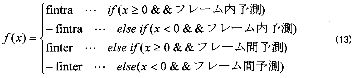
- fintra and finter in the equation (13) are parameters for determining the quantization rounding position.
- the target pixel may be a static region pixel or a motion region pixel. It is generally said that human visual characteristics are sensitive to static areas and insensitive to moving areas. However, even with pixels in the motion region, if the human eye is following this, the human visual characteristics will be sensitive.
- Figure 10 shows the input of the target pixel org (t, vpx, vpy), reconstruction rec (t, vpx, vpy), prediction pred (t,
- the coordinates have the following relationship.
- the present invention described below takes into account the inter-code noise pattern of an image encoded using inter-code when the image is intra-coded, that is, the time of the pixel of interest.
- intra coding considering the inter-code noise pattern of an image encoded using the inter-code key” will be referred to as “intra coding considering continuity on the time axis”.
- the moving picture coding apparatus according to the present invention is shown in the present embodiment.
- the invention system of FIG. 11 includes an I-frame frits force suppression control device 300 in addition to the conventional system of FIG. Further, the internal operation of transform quantization apparatus 200 is conventionally performed by an I frame flicker force prediction pressure control signal supplied from I frame flicker force suppression control apparatus 300 and a reference prediction error that is a difference between a corrected reference image and an intraframe predicted value. It is different from the method.
- the devices other than the I-frame fretting force suppression control device 300 and the transform quantization device 200 are the same as the conventional method, only the I-frame fretting force suppression control device 300 and the quantization device 200 are used for the sake of simplification. Is described below.
- the outline of the operation of the I-frame flicker force suppression control apparatus 300 in this embodiment is as follows.
- An image to be intra-encoded is previously reconstructed after being encoded using inter-encoding (hereinafter referred to as an inter-encoding).
- Inter-frame prediction, transform, quantization, inverse quantization, and inverse transform to generate inter-coded images (reconstructed images recInte t, ⁇ , ⁇ ty) and correct them.
- Formula (17) is formalized.
- the corrected reference image generation reference frame described above is preferably an image frame having the highest inter-frame correlation with the image frame to be intra-encoded. For this reason, usually, the shorter the interframe distance, the higher the interframe correlation. For this reason, the P frame that was coded immediately before is the best in coding that does not use the B frame (Fig. 12 (a)). However, if the previous P frame is flashed by lighting, the previous P frame may be used.
- the corrected reference image generation reference frame is better than the P frame immediately before encoded with a certain level of image quality, rather than the coarsely quantized B frame (FIG. 12 (b)).
- the input of the I-frame fluff force suppression control device 300 is supplied from the input MB pixel supplied from the MB buffer 101, the inter-frame prediction value supplied from the inter-frame prediction device 111, and the code amount control 106.
- the output includes an I-frame frits force suppression control signal supplied to the transform quantizer 200, a corrected reference image supplied to the transform quantizer 200 after the intra-frame prediction value is reduced, and a prediction method estimation. This is a motion vector estimation control signal for controlling the device 112.
- the I-frame flick force suppression control device in FIG. 13 it includes a conversion device 102, a quantization device 103, an inverse quantization / inverse conversion device 104, and a controller 301.
- the controller 301 calculates the I-frame frits force suppression control signal from the supplied quantization parameter, the motion vector and MB type, and the difference between the input MB and the inter-frame prediction value.
- the I frame flicker force suppression control signal is information indicating "in which region in an image frame an intra code that takes account of continuity in the time axis is applied".
- the controller 301 uses the prediction method estimation device 112 as an I frame, an inter-frame prediction method estimation (motion from the corrected reference image generation reference frame that minimizes the inter-frame prediction error with the input MB). If the process of detecting a vector and inter MB type) is stopped, the inter-frame prediction method estimation is operated by a motion vector estimation control signal.
- Conversion apparatus 102 converts the difference between the input MB and the inter-frame prediction value, and supplies the conversion coefficient to quantization apparatus 103.
- the quantization apparatus 103 quantizes the transform coefficient with a quantization step size corresponding to the supplied quantization parameter, and calculates a level.
- the inverse quantization / inverse transformation device 104 inverse quantizes the level supplied from the quantization device 103, further performs inverse frequency transformation, and returns the original level to the original spatial domain, thereby calculating a reconstruction prediction error.
- An inter-coded reconstructed image is obtained by adding the inter-frame prediction to the reconstructed prediction error, and this is output as a corrected reference image.
- the intra-frame prediction value of the corrected reference image is reduced to generate a reference prediction error.
- the reference prediction error is information indicating how long the intra code that takes account of continuity in the time axis is to be continuous in the time direction.
- the conversion device 102, the quantization device 103, and the inverse quantization / inverse conversion device 104 in the I frame flitz force suppression control device 300 are the same as those in the conventional method.
- step S1001 the pixel value src (x,
- step S1002 the second prediction error pe2 (x, x,
- the I-frame flitch force suppression control signal IFlickerControl is calculated according to Equation (20).
- qpthl is a quantization parameter threshold value (28 in this embodiment)
- a is a value greater than 0
- T gain is a gain of conversion (16 in this embodiment).
- Sth is the quantization dead zone width in inter coding in the pixel space region.
- step S1003 the second prediction error pe2 (x, y) ⁇ 0 ⁇ idx ⁇ 15, 0 ⁇ x ⁇ 3, 0 ⁇ y ⁇ 3 ⁇
- the second reconstruction prediction error re CP e2 (idx x, y) (0 ⁇ idx ⁇ 15, 0 ⁇ x ⁇ 3, 0 ⁇ y ⁇ 3 ⁇ is calculated. Furthermore, the interframe prediction value plnter idx
- reclnter idx (x, y) recpel ldx (x, y) + plnter idx (x, y) (23) This is the end of the description of the I-frame frits force suppression control device 300 in the present embodiment.
- the above-described inter code reconstruction image is output as a corrected reference image to the outside of the I frame flicker suppression control device 300.
- the corrected reference image is obtained by subtracting the intra-frame prediction value supplied from the intra-frame prediction device 110 to obtain a reference prediction error rpe (x,
- rpe idx (x, y) reclnter ldx (x, y)-plntra ldx (x, y) (24)
- Information indicating how the I frame flitch force suppression control device 300 encodes the reconstructed image of the intra code target image so as to be continuous in the time direction (I frame flitch force suppression control signal ) And information (reference prediction error) indicating how long the reconstructed image of the intra encoding target image is encoded in the time direction.
- the transform quantization apparatus 200 uses these pieces of information to perform coding in consideration of continuity in the time direction of the reconstructed image of the intra coding target image.
- a quantization apparatus 200 includes a conversion coefficient correction apparatus 201 in addition to the configuration of the conventional system shown in FIG.
- Transform coefficient correction apparatus 201 includes an I frame flitch force suppression control signal supplied from I frame flitch force suppression control apparatus 300, a reference prediction error obtained by subtracting a corrected reference image power intra-frame prediction value, and a code amount. Based on the quantization parameter supplied from the control device 106, the conversion coefficient and the DC conversion coefficient supplied from the conversion device 102 are corrected, and the corrected conversion coefficient and the corrected DC conversion coefficient are supplied to the quantization device 103. That is, the quantization value (level) of the intra code ⁇ is adaptively corrected.
- the only difference from the transform quantization apparatus in FIG. 5 is the correction of the transform coefficient and the DC transform coefficient by the transform coefficient correction apparatus 201. Therefore, only the transform coefficient correction apparatus 201 will be described below.
- the quantization parameter is qp
- the I-frame flitch force suppression control signal is IFlickerControl
- the reference prediction error is rpe (x, y) (0 ⁇ idx ⁇ 15, 0 ⁇ x ⁇ 3, 0 ⁇ y ⁇ 3 ⁇
- the conversion coefficient supplied from the converter 102 is T (x, y) ⁇ 0 ⁇ idx ⁇ 15, 0 ⁇ x ⁇ 3, 0 ⁇ y ⁇
- step S2001 the corrected conversion coefficient T, (x, y) and the corrected DC conversion coefficient TDC '(x, y) are
- step S2002 it is checked whether or not the I frame flitch force suppression control signal IFlickerControl is zero. If IFlickerControl is not 0 (if the coefficient is corrected), step S2003; otherwise, the process ends.
- step S2003 it is determined whether or not the conversion coefficient force ntral6MB is a correction target. Intral
- Step S2004 If it is not 6MB, go to Step S2004, otherwise go to Step S2005.
- step S2004 all idx, x, y ⁇ 0 ⁇ idx ⁇ 15, 0 ⁇ x ⁇ 3, 0 ⁇ y ⁇ 3 ⁇ are corrected for Equation (27) and processed. Exit.
- Qs (x, y) 2 '5 + qp' 6 / Q (qp% 6, x, y) (32)
- Qsdzl (x, y) is the quantization dead zone of the inter-coding.
- ope ⁇ (C, qs, x, y) ((C + 0.5 x sign C) x qs) I qs) * qs (34) where sign (C) is -1 if C ⁇ 0, otherwise Is a function that returns 1.
- conditionA (idx, x, y) True in Equation (27)
- the level force obtained by quantizing the difference between the corrected reference image and the intraframe prediction image and the level of the intra code ⁇ become.
- conditionA (idx, x, y) True in Equation (33)
- the level obtained by quantizing the difference between the corrected reference image and the intra-frame prediction image by rounding off the quantization characteristic is It becomes the level of the intra code ⁇ .
- the rounding quantization characteristic is used, the reconstructed image is more accurately continuous in the time direction.
- equation (33) may be used instead of equation (27).
- step S2006 it is determined whether or not the I frame flitch force suppression control signal IFlickerControl is 1. If not 1 (if the DC conversion coefficient is corrected), step S2007, otherwise, the process ends.
- step S2007 the DC conversion coefficient of Equation (35) is corrected for all X, y ⁇ 0 ⁇ x ⁇ 3, 0 ⁇ y ⁇ 3 ⁇ conversion coefficients, and the process ends.
- QsDC (x, y) 2 16 6 IQ (qp% 6,0,) (39)
- Qsdz2 (x, y) is a quantization dead zone of inter coding in the DC transform domain.
- conditionB in Equation (35) it is possible to prevent correction of excessive intra-coded quantization values (of course, it is possible to use a larger value for Qsdz2, but DC conversion
- the quantization dead zone of the inter-code in the region has the most stable effect).
- the correction of the DC conversion coefficient may be calculated by Expression (40) instead of Expression (35).
- iope ⁇ (RTDC (x, y), QsD (JC.v), x, y) v, i rue) TDC tdx (x, y)... else
- conditionB (x, y) True in equation (35)
- the level force obtained by quantizing the difference between the corrected reference image and the intraframe prediction image is the level of the intra code key.
- conditionB (x, y) True in Equation (40)
- the level obtained by quantizing the difference between the corrected reference image and the intra-frame prediction image by rounding off the quantization characteristic is the intra code. It becomes the level of ⁇ . Using the rounding quantization characteristic, the reconstructed image becomes more accurate in the time direction.
- the prediction error conversion coefficient is corrected with the reference prediction error conversion coefficient, and the reconstructed prediction error of the target pixel in the I frame is expressed by Equation (42).
- recpe ⁇ vpx 3 , vpy 3 ) IQIT [QT [rpeQ, vpx ⁇ , vpy 3 )]]]]] (42)
- the reconstruction prediction error in the invention example (Fig. 17) is the same as that in the conventional example (Fig. 10). It is smaller than the reconstruction prediction error by the quantization width.
- the reference prediction error is generated by the inter-code image power, the above-described effect can be obtained regardless of whether the pixel of interest is a still region or a motion region.
- the reference prediction error is calculated in units of blocks, the above-described suppression of the I frame flicker force is applied adaptively for each block in the image frame.
- a moving image when a moving image is encoded using not only an I frame but also inter-frame prediction such as a P frame and a B frame, a moving image including a moving scene and a moving region is encoded. Even when hesitating, it is possible to effectively reduce the I-frame flickering force.
- the I-frame frits force suppression control apparatus 300 needs to perform transform, quantization, inverse quantization, and inverse transform processes in order to calculate a corrected reference image. there were.
- a simpler I frame flitch force suppression control device 300 that does not require the transformation, quantization, inverse quantization, and inverse transformation will be described.
- the moving picture coding apparatus of the present embodiment has the same configuration except for the I frame flitch force suppression control apparatus 300 of the first embodiment. Therefore, for simplicity of explanation, the I frame in the present embodiment is the same. Only the Muflitz force suppression control device 300 will be described below.
- I frame flitz force suppression control apparatus 300 With reference to FIG. 18, the configuration of I frame flitz force suppression control apparatus 300 in the present embodiment will be described.
- the transform device 102, the quantization device 103, and the inverse quantization / inverse transform device 104 are deleted.
- the controller 301 is the same as that in the first embodiment.
- the corrected reference image obtained in the present embodiment is the inter-frame prediction image when the intra-coding target image is subjected to the correction reference image generation reference frame force inter-frame prediction.
- the corrected reference image is equivalent to an inter-coded reconstructed image in which the first term of Equation (17) in Example 1 is zero.
- the principle in which the first term of the above equation (17) is set to zero is “a continuous image in the time direction matches the image and the inter-frame prediction image. Therefore, the prediction error is small. We use the tendency that the prediction error becomes zero after quantization. As a result, a function equivalent to that of the I-frame fritting force suppression control device of the first embodiment is realized at a lower calculation cost because the prediction error conversion, quantization, inverse quantization, and inverse conversion are not performed.
- step S3001 the input MB pixel value src (x, y) ⁇ 0 ⁇ x ⁇ 15, 0 ⁇ y ⁇ 15 ⁇ and the corrected reference inter-frame prediction value Pinter (x, y) from the image generation reference frame ⁇ 0 ⁇ idx ⁇ 15, 0 ⁇ x ⁇ 3
- step S3002 the second prediction error pe2 (x, y), the MB type, and the quantization parameter
- the I frame flitch force suppression control signal IFlickerControl is calculated by the equation (20) (same as step S1002).
- qpthl is a threshold value of the quantization parameter (28 in this embodiment).
- inter-frame prediction value is output to the outside of the I-frame frits force suppression control device 300 as a corrected reference image.
- the intra-frame prediction value supplied from the intra-frame prediction device 110 is subtracted, and the reference prediction error rpe (x, y) 0 ⁇ idx ⁇ 15, 0
- the I frame flits force suppression controller 300 of this embodiment uses the I frame flits as in the first embodiment. A force suppression control signal and a reference prediction error are obtained.
- the transform quantization apparatus 200 in FIG. 20 includes a transform apparatus 102B having the same function as the transform apparatus 102 in addition to the configuration of the conventional system in FIG.
- the converter 102B is supplied with the reference prediction
- the error is converted in the same way as the prediction error of the converter 102, and the reference conversion coefficient and the reference DC conversion coefficient are output.
- step S4001 all transform coefficients T (X, y) ⁇ 0 ⁇ idx ⁇ 15, 0 ⁇ x ⁇ 3, 0 ⁇ y ⁇ 3 ⁇
- Step S4001 is the operation of the coefficient quantization itself of the conventional method.
- Steps 4002 to S4005 are operations added by the invention.
- step S4002 it is determined whether or not the I frame flitch force suppression control signal IFlickerControl is zero. If IFlickerControl is not 0 (if the coefficient is corrected), step S4003; otherwise, the process ends.
- step S4003 a counter countL indicating the number of corrected coefficients is initialized to zero.
- step S4004 countL force is greater than or equal to 3 ⁇ 456 (whether or not all idx, x, y ⁇ 0 ⁇ idx ⁇ 15, 0 ⁇ x ⁇ 3, 0 ⁇ y ⁇ 3 ⁇ coefficients are corrected) Check, and if countL is 256 or more, the process ends, otherwise go to step S4005.
- step S4005 level L (x, y) is corrected by equation (44), and countL is incremented by one.
- step S5001 all DC conversion coefficients TDC (x, x,
- Step S5001 is the operation of the conventional DC coefficient quantization itself, and subsequent steps S5002 to S5005 are operations added by the invention.
- step S5002 it is checked whether or not the I frame flitch force suppression control signal IFlickerControl is 1 and the MB type is Slntral6MB. If IFlickerControl is 1 and the MB type power is Slntral6MB (if the DC coefficient is corrected), step S5003; otherwise, the process ends.
- step S5003 the counter countDCL indicating the number of corrected DC coefficients is initialized to zero.
- step S5004 it is checked whether countDCL is 16 or more (whether DC coefficients of all X, y ⁇ 0 ⁇ x ⁇ 3, 0 ⁇ y ⁇ 3 ⁇ are corrected), and countDCL is 16 If so, the process ends. Otherwise, the process proceeds to step S5005.
- step S5005 the level LDC (x, y) is corrected by equation (50), countDCL is incremented by 1, and the flow proceeds to step S5004.
- iDC (x — ⁇ L £ C (x, ... if (conditionB (idx, x, y) True)
- transform quantizing apparatus 200 in the present embodiment described above encodes a video using not only an I frame but also inter-frame prediction such as a P frame and a B frame, as in the first embodiment.
- inter-frame prediction such as a P frame and a B frame
- the conversion quantizer 200 does not have to calculate “the conversion coefficient of the reference prediction error”.
- the moving picture coding apparatus according to the present invention uses a transform quantization apparatus capable of reducing the frame-flick force.
- the transform quantization apparatus 200 includes a prediction error correction apparatus 202 in addition to the configuration of the conventional method of FIG.
- the prediction error correction device 202 corrects the prediction error based on the supplied I frame flicker force suppression control signal / reference prediction error, and supplies the corrected prediction error to the conversion device 102.
- the devices other than the prediction error correction device 202 are the same as those of the conventional method of FIG. Accordingly, only the operation of the prediction error correction apparatus 202 will be described below with reference to the flowchart of FIG.
- step S6001 whether or not the I frame flitch force suppression control signal IFlickerControl is 0 is checked. The If IFlickerControl is not 0 (if the prediction error is corrected), step S6002 If not, the process ends.
- step S6002 a counter countpe indicating the number of pixels of the corrected prediction error is initialized to zero.
- step S6003 countpe is greater than or equal to 256 (whether or not the prediction error of all idx, x, y ⁇ 0 ⁇ idx ⁇ 15 0 ⁇ x ⁇ 3 0 ⁇ y ⁇ 3 ⁇ is corrected) Check and if countpe is greater than or equal to 256, the process ends; otherwise, go to step S6004.
- step S6004 the prediction error pe (x, y) (0 ⁇ idx ⁇ 15 0 ⁇ x ⁇ 3 0 ⁇ by equation (54)
- 13 in the equation (56) is a real number of 1 or more (2 in this embodiment).
- the reference prediction error is a difference between the corrected reference image described in the first embodiment or the second embodiment and intra-frame prediction.
- the prediction error is the difference between the input MB and the intraframe prediction.
- the transform quantization apparatus 200 according to the present embodiment can code the above-described corrected reference image instead of the intra code target image in intra coding.
- Equation (54) which does not replace all intra encoding target images unconditionally, also applies force, so that only the images considered to be continuous in the time direction are subject to the intra encoding target described above. Replace the image with a corrected reference image!
- the invention is described when the invention is applied to the moving picture coding apparatus using the intra-frame prediction.
- the invention is applied to the moving picture coding apparatus without using the intra-frame prediction. It is also possible.
- the above-described intra-frame prediction value plntra (x, y) can be set to 0.
- Embodiment 1 is the amount obtained by transforming and quantizing an inter-coded reconstructed image as a quantized value of intra coding. Child values will be used.
- the configuration of the transform quantization apparatus 200 may be that of the third embodiment.
- Embodiment 2 converts the inter-frame prediction image from the corrected reference image generation reference frame as the quantized value of the intra code ⁇ , A quantized value obtained by quantization is used.
- the configuration of the conversion quantizer 200 may be that of the third embodiment.
- the operation of the fourth embodiment is performed from an inter-code reconstructed image or a corrected reference image generation reference frame as a target image for intra coding. These inter-frame prediction images are used.
- FIG. 25 is a general block configuration diagram of an information processing system that implements the moving picture coding apparatus according to the present invention.
- the information processing system shown in FIG. 25 includes a processor A1001, a program memory A1002, and a storage.
- the storage media A1003 and A1004 may be separate storage media or storage areas having the same storage medium power.
- a magnetic storage medium such as a hard disk can be used as the storage medium.
- a decoding device that receives the bit stream generated by the moving image coding device of the first to sixth embodiments as an input and outputs an image obtained by decoding the bit stream will be described. To do.
- the decoding apparatus includes an entropy decoding apparatus D101, an inverse quantization / inverse conversion apparatus D102, a frame memory D103, an intraframe prediction apparatus D104, and an interframe prediction apparatus D105.
- the entropy decoding device D101 entropy-decodes the bit sequence such as the level multiplexed in the bitstream, the quantization parameter, the intra MB type, the inter MB type, the prediction direction, the motion vector, and the like. Return to a numeric value.
- the inverse quantization / inverse transformation device D102 returns the level supplied from the entropy decoding device D101 to the original pixel space by inverse quantization and inverse transformation.
- the level returned to the original pixel space is called a prediction error.
- the prediction value supplied from the SW 100 is added to the prediction error, and stored as a reconstructed image frame in the frame memory D103.
- the frame memory D103 has a configuration in which the frame memory A107, the in-loop filter device 108, and the frame memory B109 described in the video encoding device are integrated.
- the frame memory D103 monitors the display time of the stored reconstructed image frame, and outputs the reconstructed image frame at the display time.
- the intra-frame prediction device D104 uses the intra MB and prediction direction supplied from the reconstructed image frame stored in the frame memory 105. -Based intra-frame prediction apparatus for encoding apparatus
- an intra-frame prediction image is generated.
- the inter-frame prediction device D105 the reconstructed image frame (reference) Based on the supplied inter MB type and motion vector, an inter-frame prediction image is generated in the same manner as the inter-frame prediction device 111 of the encoding device.
- SW100 When the MB type supplied from the entropy decoding device D101 is intra MB, SW100 outputs the intra-frame prediction image supplied from the intra-frame prediction device D104 as a prediction value.
- the inter-frame prediction image supplied from the prediction device D105 is output as a prediction value.
- the moving picture decoding apparatus can decode an input bit stream and reconstruct an image.
Abstract
Description


Claims
Priority Applications (4)
| Application Number | Priority Date | Filing Date | Title |
|---|---|---|---|
| JP2006550785A JP5234241B2 (en) | 2004-12-28 | 2005-12-27 | Moving picture encoding method, apparatus using the same, and computer program |
| EP20050822272 EP1845735A4 (en) | 2004-12-28 | 2005-12-27 | Moving picture encoding method, and apparatus and computer program using the same |
| CN2005800449842A CN101091393B (en) | 2004-12-28 | 2005-12-27 | Moving picture encoding method, device using the same |
| US11/794,142 US8325799B2 (en) | 2004-12-28 | 2005-12-27 | Moving picture encoding method, device using the same, and computer program |
Applications Claiming Priority (2)
| Application Number | Priority Date | Filing Date | Title |
|---|---|---|---|
| JP2004-379778 | 2004-12-28 | ||
| JP2004379778 | 2004-12-28 |
Publications (1)
| Publication Number | Publication Date |
|---|---|
| WO2006070787A1 true WO2006070787A1 (en) | 2006-07-06 |
Family
ID=36614900
Family Applications (1)
| Application Number | Title | Priority Date | Filing Date |
|---|---|---|---|
| PCT/JP2005/023862 WO2006070787A1 (en) | 2004-12-28 | 2005-12-27 | Moving picture encoding method, device using the same, and computer program |
Country Status (6)
| Country | Link |
|---|---|
| US (1) | US8325799B2 (en) |
| EP (1) | EP1845735A4 (en) |
| JP (1) | JP5234241B2 (en) |
| KR (1) | KR100945985B1 (en) |
| CN (1) | CN101091393B (en) |
| WO (1) | WO2006070787A1 (en) |
Cited By (3)
| Publication number | Priority date | Publication date | Assignee | Title |
|---|---|---|---|---|
| JP2008177834A (en) * | 2007-01-18 | 2008-07-31 | Nippon Hoso Kyokai <Nhk> | Coding device, and program |
| JP2012509012A (en) * | 2008-11-12 | 2012-04-12 | トムソン ライセンシング | I-frame flicker removal for GOP parallel multi-thread video coding |
| US9210431B2 (en) | 2008-11-13 | 2015-12-08 | Thomson Licensing | Multiple thread video encoding using GOP merging and bit allocation |
Families Citing this family (45)
| Publication number | Priority date | Publication date | Assignee | Title |
|---|---|---|---|---|
| US7663017B2 (en) * | 2003-07-30 | 2010-02-16 | Institut Pasteur | Transgenic mice having a human major histocompatability complex (MHC) phenotype, experimental uses and applications |
| US8422546B2 (en) * | 2005-05-25 | 2013-04-16 | Microsoft Corporation | Adaptive video encoding using a perceptual model |
| JP4449915B2 (en) * | 2006-02-08 | 2010-04-14 | ソニー株式会社 | Encoding apparatus, encoding method and program, and recording medium |
| US7995649B2 (en) | 2006-04-07 | 2011-08-09 | Microsoft Corporation | Quantization adjustment based on texture level |
| US8059721B2 (en) | 2006-04-07 | 2011-11-15 | Microsoft Corporation | Estimating sample-domain distortion in the transform domain with rounding compensation |
| US8503536B2 (en) | 2006-04-07 | 2013-08-06 | Microsoft Corporation | Quantization adjustments for DC shift artifacts |
| US20070237237A1 (en) * | 2006-04-07 | 2007-10-11 | Microsoft Corporation | Gradient slope detection for video compression |
| US8711925B2 (en) | 2006-05-05 | 2014-04-29 | Microsoft Corporation | Flexible quantization |
| US8036270B2 (en) * | 2006-07-27 | 2011-10-11 | Sharp Laboratories Of America, Inc. | Intra-frame flicker reduction in video coding |
| US8238424B2 (en) | 2007-02-09 | 2012-08-07 | Microsoft Corporation | Complexity-based adaptive preprocessing for multiple-pass video compression |
| US20080240257A1 (en) * | 2007-03-26 | 2008-10-02 | Microsoft Corporation | Using quantization bias that accounts for relations between transform bins and quantization bins |
| US8498335B2 (en) * | 2007-03-26 | 2013-07-30 | Microsoft Corporation | Adaptive deadzone size adjustment in quantization |
| US8243797B2 (en) | 2007-03-30 | 2012-08-14 | Microsoft Corporation | Regions of interest for quality adjustments |
| US8442337B2 (en) | 2007-04-18 | 2013-05-14 | Microsoft Corporation | Encoding adjustments for animation content |
| US8331438B2 (en) * | 2007-06-05 | 2012-12-11 | Microsoft Corporation | Adaptive selection of picture-level quantization parameters for predicted video pictures |
| US8363719B2 (en) * | 2007-10-29 | 2013-01-29 | Canon Kabushiki Kaisha | Encoding apparatus, method of controlling thereof, and computer program |
| EP2071852A1 (en) * | 2007-12-11 | 2009-06-17 | Alcatel Lucent | Process for delivering a video stream over a wireless bidirectional channel between a video encoder and a video decoder |
| ATE526787T1 (en) * | 2007-12-11 | 2011-10-15 | Alcatel Lucent | METHOD FOR DELIVERING A VIDEO STREAM OVER A WIRELESS CHANNEL |
| US20100278236A1 (en) * | 2008-01-17 | 2010-11-04 | Hua Yang | Reduced video flicker |
| US8654844B1 (en) * | 2008-02-04 | 2014-02-18 | Zenverge, Inc. | Intra frame beating effect reduction |
| CN101960854B (en) * | 2008-03-10 | 2013-12-18 | 汤姆森许可贸易公司 | Method and apparatus for predictive frame selection supporting enhanced efficiency and subjective quality |
| US8189933B2 (en) | 2008-03-31 | 2012-05-29 | Microsoft Corporation | Classifying and controlling encoding quality for textured, dark smooth and smooth video content |
| US8897359B2 (en) | 2008-06-03 | 2014-11-25 | Microsoft Corporation | Adaptive quantization for enhancement layer video coding |
| KR101518237B1 (en) * | 2008-09-01 | 2015-05-15 | 삼성전자주식회사 | Method and apparatus for inverse quantization, and method and apparatus for decoding of image |
| CN102656884A (en) * | 2009-12-16 | 2012-09-05 | 国际商业机器公司 | Video coding using pixel-streams |
| US9294755B2 (en) | 2010-10-20 | 2016-03-22 | Raytheon Company | Correcting frame-to-frame image changes due to motion for three dimensional (3-D) persistent observations |
| RU2606306C2 (en) | 2010-11-26 | 2017-01-10 | Нек Корпорейшн | Video encoding device, video decoding device, video encoding method, video decoding method and program |
| US8923401B2 (en) * | 2011-05-31 | 2014-12-30 | Raytheon Company | Hybrid motion image compression |
| EP2536143B1 (en) * | 2011-06-16 | 2015-01-14 | Axis AB | Method and a digital video encoder system for encoding digital video data |
| US8913656B2 (en) * | 2011-10-14 | 2014-12-16 | Mediatek Inc. | Method and apparatus for in-loop filtering |
| CN102497553B (en) * | 2011-12-12 | 2017-08-25 | 深圳市云宙多媒体技术有限公司 | A kind of video decoding post-processing approach and device |
| US9230333B2 (en) | 2012-02-22 | 2016-01-05 | Raytheon Company | Method and apparatus for image processing |
| US9723314B2 (en) | 2012-02-29 | 2017-08-01 | Smsc Holdings Sarl | Flicker reduction circuit and method for compressed video transmission |
| CN103731673B (en) * | 2012-10-10 | 2017-02-22 | 浙江大华技术股份有限公司 | Method and device for encoding video |
| EP3010232A4 (en) * | 2013-06-12 | 2017-01-25 | Mitsubishi Electric Corporation | Image encoding device, image encoding method, image decoding device, and image decoding method |
| US20160205398A1 (en) * | 2015-01-08 | 2016-07-14 | Magnum Semiconductor, Inc. | Apparatuses and methods for efficient random noise encoding |
| KR102338980B1 (en) | 2015-03-23 | 2021-12-13 | 삼성전자주식회사 | Encoder for adjusting quantization coefficient to remove flicker and device including the same |
| US11095911B2 (en) | 2016-02-16 | 2021-08-17 | Samsung Electronics Co., Ltd. | Method and apparatus for encoding image |
| US10341565B2 (en) | 2016-05-10 | 2019-07-02 | Raytheon Company | Self correcting adaptive low light optical payload |
| US10715819B2 (en) | 2017-04-26 | 2020-07-14 | Canon Kabushiki Kaisha | Method and apparatus for reducing flicker |
| WO2019084792A1 (en) * | 2017-10-31 | 2019-05-09 | 深圳市大疆创新科技有限公司 | Coding method and device |
| CN110087070B (en) * | 2018-01-26 | 2021-04-02 | 翔升(上海)电子技术有限公司 | Data compression method, device, equipment and medium |
| DE102018112215B3 (en) * | 2018-04-30 | 2019-07-25 | Basler Ag | Quantizer determination, computer readable medium, and apparatus implementing at least two quantizers |
| US11057617B2 (en) * | 2018-08-03 | 2021-07-06 | Tencent America LLC | Method and apparatus for video coding |
| CN110232672A (en) * | 2019-06-20 | 2019-09-13 | 合肥工业大学 | A kind of denoising method and system of exercise data |
Citations (7)
| Publication number | Priority date | Publication date | Assignee | Title |
|---|---|---|---|---|
| JPH08251593A (en) * | 1995-03-10 | 1996-09-27 | Sony Corp | Quantization circuit |
| JP2002359850A (en) * | 2001-02-15 | 2002-12-13 | Ricoh Co Ltd | Memory usage scheme for performing wavelet processing |
| JP2003235042A (en) * | 2002-02-12 | 2003-08-22 | Sony Corp | Image encoding apparatus and encoding method thereof |
| JP2005039321A (en) * | 2003-07-15 | 2005-02-10 | Nippon Hoso Kyokai <Nhk> | Flicker reduction quantizer, flicker reduction quantization method, and program therefor |
| JP2005318468A (en) * | 2004-04-30 | 2005-11-10 | Nippon Hoso Kyokai <Nhk> | In-screen predictive coding device, its method, and its program |
| JP2005323315A (en) * | 2004-05-11 | 2005-11-17 | Nippon Hoso Kyokai <Nhk> | Prediction information/quantization value control compression coding apparatus, program, and method |
| JP2005348008A (en) * | 2004-06-02 | 2005-12-15 | Nippon Telegr & Teleph Corp <Ntt> | Moving picture coding method, moving picture coder, moving picture coding program and computer-readable recording medium with record of the program |
Family Cites Families (32)
| Publication number | Priority date | Publication date | Assignee | Title |
|---|---|---|---|---|
| JP3187097B2 (en) | 1991-10-17 | 2001-07-11 | 株式会社東芝 | Code amount distribution method in moving picture coding and moving picture coding method and apparatus using the same |
| JP3004799B2 (en) * | 1992-02-17 | 2000-01-31 | ジー・シー・テクノロジー株式会社 | Image coding method and apparatus |
| US5410350A (en) * | 1992-10-28 | 1995-04-25 | Sony Corporation | Motion picture encoding and/or decoding system |
| ATE246864T1 (en) * | 1994-06-06 | 2003-08-15 | Sci Worx Gmbh | METHOD FOR CODING/DECODING A DATA STREAM |
| JPH08116539A (en) * | 1994-10-17 | 1996-05-07 | Hitachi Ltd | Dynamic image coder and dynamic image coding method |
| JP3552811B2 (en) | 1995-09-29 | 2004-08-11 | 三菱電機株式会社 | Digital video signal encoding device and decoding device |
| JP3778606B2 (en) * | 1996-02-16 | 2006-05-24 | 日本放送協会 | Image quality improvement device |
| JP3575508B2 (en) * | 1996-03-04 | 2004-10-13 | Kddi株式会社 | Encoded video playback device |
| CA2185753C (en) * | 1996-03-04 | 2000-09-12 | Hideo Ohira | Digital image decoding apparatus |
| US6208689B1 (en) * | 1996-03-04 | 2001-03-27 | Mitsubishi Denki Kabushiki Kaisha | Method and apparatus for digital image decoding |
| JP3870439B2 (en) * | 1996-03-22 | 2007-01-17 | 三菱電機株式会社 | Motion compensated prediction decoding apparatus |
| US6101276A (en) * | 1996-06-21 | 2000-08-08 | Compaq Computer Corporation | Method and apparatus for performing two pass quality video compression through pipelining and buffer management |
| JP4214562B2 (en) * | 1998-06-26 | 2009-01-28 | ソニー株式会社 | Decoding device |
| US6584154B1 (en) * | 1998-11-26 | 2003-06-24 | Oki Electric Industry Co., Ltd. | Moving-picture coding and decoding method and apparatus with reduced computational cost |
| JP2000165861A (en) * | 1998-11-26 | 2000-06-16 | Oki Electric Ind Co Ltd | Moving image decoding device |
| JP2000165875A (en) * | 1998-11-26 | 2000-06-16 | Oki Electric Ind Co Ltd | Moving image resolution converting and encoding/ decoding device with a little memory capacity |
| US6639942B1 (en) * | 1999-10-21 | 2003-10-28 | Toshiba America Electronic Components, Inc. | Method and apparatus for estimating and controlling the number of bits |
| JP2002202799A (en) * | 2000-10-30 | 2002-07-19 | Fujitsu Ltd | Voice code conversion apparatus |
| US6831947B2 (en) * | 2001-03-23 | 2004-12-14 | Sharp Laboratories Of America, Inc. | Adaptive quantization based on bit rate prediction and prediction error energy |
| JP3732760B2 (en) * | 2001-06-29 | 2006-01-11 | 株式会社東芝 | Object recognition apparatus and object recognition method |
| FR2830143B1 (en) * | 2001-09-21 | 2004-02-27 | St Microelectronics Sa | METHOD AND DEVICE FOR COMPRESSING AN IMAGE SIGNAL |
| US20030202606A1 (en) * | 2002-04-05 | 2003-10-30 | Michael Tinker | Multi-phase processing for real-time display of a compressed video bitstream |
| US7336720B2 (en) * | 2002-09-27 | 2008-02-26 | Vanguard Software Solutions, Inc. | Real-time video coding/decoding |
| CN1225126C (en) * | 2002-10-09 | 2005-10-26 | 中国科学院计算技术研究所 | Space predicting method and apparatus for video encoding |
| KR100498333B1 (en) * | 2002-10-26 | 2005-07-01 | 엘지전자 주식회사 | Quantization parameter decision method |
| KR20040062109A (en) * | 2002-12-31 | 2004-07-07 | 엘지전자 주식회사 | Method for moving picture coding |
| US8040949B2 (en) * | 2003-01-09 | 2011-10-18 | The Regents Of The University Of California | Video encoding methods and devices |
| EP1747677A2 (en) * | 2004-05-04 | 2007-01-31 | Qualcomm, Incorporated | Method and apparatus to construct bi-directional predicted frames for temporal scalability |
| EP1754378A1 (en) * | 2004-05-25 | 2007-02-21 | Koninklijke Philips Electronics N.V. | Method and device for encoding digital video data |
| US8311113B2 (en) * | 2004-11-12 | 2012-11-13 | Broadcom Corporation | Method and system for using motion prediction to equalize video quality across intra-coded frames |
| JP2006174415A (en) * | 2004-11-19 | 2006-06-29 | Ntt Docomo Inc | Image decoding apparatus, image decoding program, image decoding method, image encoding apparatus, image encoding program, and image encoding method |
| ATE516666T1 (en) * | 2005-12-23 | 2011-07-15 | Koninkl Philips Electronics Nv | DEVICE AND METHOD FOR PROCESSING A DATA STREAM |
-
2005
- 2005-12-27 EP EP20050822272 patent/EP1845735A4/en not_active Ceased
- 2005-12-27 CN CN2005800449842A patent/CN101091393B/en not_active Expired - Fee Related
- 2005-12-27 WO PCT/JP2005/023862 patent/WO2006070787A1/en active Application Filing
- 2005-12-27 US US11/794,142 patent/US8325799B2/en active Active
- 2005-12-27 JP JP2006550785A patent/JP5234241B2/en active Active
- 2005-12-27 KR KR20077014070A patent/KR100945985B1/en active IP Right Grant
Patent Citations (7)
| Publication number | Priority date | Publication date | Assignee | Title |
|---|---|---|---|---|
| JPH08251593A (en) * | 1995-03-10 | 1996-09-27 | Sony Corp | Quantization circuit |
| JP2002359850A (en) * | 2001-02-15 | 2002-12-13 | Ricoh Co Ltd | Memory usage scheme for performing wavelet processing |
| JP2003235042A (en) * | 2002-02-12 | 2003-08-22 | Sony Corp | Image encoding apparatus and encoding method thereof |
| JP2005039321A (en) * | 2003-07-15 | 2005-02-10 | Nippon Hoso Kyokai <Nhk> | Flicker reduction quantizer, flicker reduction quantization method, and program therefor |
| JP2005318468A (en) * | 2004-04-30 | 2005-11-10 | Nippon Hoso Kyokai <Nhk> | In-screen predictive coding device, its method, and its program |
| JP2005323315A (en) * | 2004-05-11 | 2005-11-17 | Nippon Hoso Kyokai <Nhk> | Prediction information/quantization value control compression coding apparatus, program, and method |
| JP2005348008A (en) * | 2004-06-02 | 2005-12-15 | Nippon Telegr & Teleph Corp <Ntt> | Moving picture coding method, moving picture coder, moving picture coding program and computer-readable recording medium with record of the program |
Non-Patent Citations (2)
| Title |
|---|
| IGUCHI K. ET AL.: "H.264 Fugoka ni okeru Intramode no Flicker Teigen Shuho. (A Study of Reducing Flicker of H.264 in Intra Mode Coding)", FORUM ON INFORMATION TECHNOLOGY (FIT2003), IPPAN KOEN RONBUNSHU, vol. 3, 25 August 2003 (2003-08-25), pages 277 - 278, XP003004602 * |
| SAKAIDA S. ET AL.: "Tekio Ryoshika ni yoru AVC/H.264 Intraframe no Flicker Yokusei. (Adaptive Quantization Control for Reducing Flicker of AVC/H.264 Intra Frames)", DAI 3 KAI FORUM ON INFORMATION TECHNOLOGY (FIT2004), JOHO KOGAKU GIJUTSU LETTERS, vol. 3, 20 August 2004 (2004-08-20), pages 225 - 227, XP003004603 * |
Cited By (3)
| Publication number | Priority date | Publication date | Assignee | Title |
|---|---|---|---|---|
| JP2008177834A (en) * | 2007-01-18 | 2008-07-31 | Nippon Hoso Kyokai <Nhk> | Coding device, and program |
| JP2012509012A (en) * | 2008-11-12 | 2012-04-12 | トムソン ライセンシング | I-frame flicker removal for GOP parallel multi-thread video coding |
| US9210431B2 (en) | 2008-11-13 | 2015-12-08 | Thomson Licensing | Multiple thread video encoding using GOP merging and bit allocation |
Also Published As
| Publication number | Publication date |
|---|---|
| CN101091393A (en) | 2007-12-19 |
| EP1845735A1 (en) | 2007-10-17 |
| US8325799B2 (en) | 2012-12-04 |
| KR100945985B1 (en) | 2010-03-09 |
| KR20070086494A (en) | 2007-08-27 |
| US20080101465A1 (en) | 2008-05-01 |
| JP5234241B2 (en) | 2013-07-10 |
| CN101091393B (en) | 2012-03-07 |
| JPWO2006070787A1 (en) | 2008-08-07 |
| EP1845735A4 (en) | 2009-07-15 |
Similar Documents
| Publication | Publication Date | Title |
|---|---|---|
| WO2006070787A1 (en) | Moving picture encoding method, device using the same, and computer program | |
| JP3796217B2 (en) | Optimal scanning method of transform coefficient for encoding / decoding still and moving images | |
| KR101608426B1 (en) | Method for predictive intra coding/decoding for video and apparatus for same | |
| JP4650173B2 (en) | Encoding apparatus, encoding method, encoding method program, and recording medium recording the encoding method program | |
| JP2618083B2 (en) | Image recovery method and apparatus | |
| US8553768B2 (en) | Image encoding/decoding method and apparatus | |
| JP4247680B2 (en) | Encoding apparatus, encoding method, encoding method program, and recording medium recording the encoding method program | |
| JP2004343774A (en) | Video encoding/decoding method and apparatus using residue prediction of video | |
| KR20100027384A (en) | Method and apparatus for determining a prediction mode | |
| KR20070032111A (en) | Method and apparatus for loseless encoding and decoding image | |
| KR20090097688A (en) | Method and apparatus of encoding/decoding image based on intra prediction | |
| JP2006246474A (en) | Prediction image generation method and apparatus using single coding mode for all color components, and image and video encoding and decoding methods and apparatuses using the same | |
| KR20060121535A (en) | Encoder and decoder for reducing blocking phenomenon, method therefor, and recording medium storing a program to implement thereof | |
| KR20080082143A (en) | An image encoding/decoding method and apparatus | |
| KR100718121B1 (en) | A image encoding/decoding methods and apparatus using residue prediction of image | |
| WO2015008417A1 (en) | Video coding device, video decoding device, video coding method, video decoding method, and program | |
| KR20090087767A (en) | Method for predictive intra coding for image data | |
| KR100718122B1 (en) | Lossless color image coding method and apparatus using inter-plane prediction | |
| KR100949475B1 (en) | Apparatus and method for determining scan pattern, and Apparatus and method for encoding image data using the same, and method for decoding image data using the same | |
| KR100571814B1 (en) | Image coding method and apparatus using spatial predictive coding of chrominance | |
| KR100647297B1 (en) | Image coding method and apparatus using residue transform | |
| KR101639434B1 (en) | Wyner-Ziv coding and decoding system and method | |
| JP3738511B2 (en) | Video coding system | |
| KR20080013843A (en) | Method and apparatus for loseless encoding and decoding image | |
| KR20160053848A (en) | Method for predictive intra coding/decoding for video and apparatus for same |
Legal Events
| Date | Code | Title | Description |
|---|---|---|---|
| 121 | Ep: the epo has been informed by wipo that ep was designated in this application | ||
| DPE1 | Request for preliminary examination filed after expiration of 19th month from priority date (pct application filed from 20040101) | ||
| WWE | Wipo information: entry into national phase |
Ref document number: 1020077014070 Country of ref document: KR |
|
| WWE | Wipo information: entry into national phase |
Ref document number: 200580044984.2 Country of ref document: CN Ref document number: 2006550785 Country of ref document: JP Ref document number: 11794142 Country of ref document: US |
|
| NENP | Non-entry into the national phase |
Ref country code: DE |
|
| WWE | Wipo information: entry into national phase |
Ref document number: 2005822272 Country of ref document: EP |
|
| WWP | Wipo information: published in national office |
Ref document number: 2005822272 Country of ref document: EP |
|
| WWP | Wipo information: published in national office |
Ref document number: 11794142 Country of ref document: US |