METHODS OF USING SONICATIQN TO COUPLE A HEAT SINK TO A HEAT-GENERATING COMPONENT
FIELD The invention pertains to heat sinks coupled to heat-generating components via thermal interface materials and to methods of coupling such components using sonication.
BACKGROUND
The current trend in electronics is to reduce the size and increase the number of components, for example, integrated circuit chips (IC chips) mounted per unit area of a substrate, for example, a printed circuit board (PCB). Generally, these components generate heat that, if allowed to build up, can cause failure of a component if its temperature exceeds some threshold level. Typically, heat sinks are used to accelerate the dissipation of thermal energy from these heat-generating components. Generally, the heat sink is attached to the substrate with mechanical devices such as, for example, rivets, clips, clamps, and threaded fasteners such that the heat sink is in alignment with and urged toward the heat-generating component. Surface irregularities in both the component surface and the opposing heat sink surface prevent perfect contact between them. The resulting air gaps act as a heat insulator and reduce the efficiency of heat transfer. Typically, a thermal interface material (TIM) is interposed between the component surface and the opposing heat sink surface in an attempt to displace the air, fill the irregularities in the surfaces, and improve the efficiency of heat transfer.
Generally, a TIM comprises a binder and one or more thermally conductive fillers. The overall thermal efficiency of an assembly comprising the heat-generating component, the TBVI, and the heat sink is affected by the bulk thermal conductivity and the thickness of the TBVI, as well as the ability of the TBVI to wet-out the surfaces, displace air, and fill in the surface irregularities. Often a static pressure is applied to the assembly to urge the heat sink toward the heat-generating component, thus decreasing the thickness of the TBVI and, in some cases, improving wet-out. However, practical considerations, such as the mechanical strength of the heat-generating component, limit the maximum allowable applied pressure.
Typically, increasing the loading of thermally conductive fillers in the binder increases the bulk thermal conductivity of the TEvI. However, increasing the loading of filler also increases the viscosity of the TBVI, thus increasing the static force and/or the time required to achieve a given reduction in thickness of the TIM. The higher loading may also prevent the TIM from reducing in thickness to the desired value under the applied pressure. Thus, despite increasing the bulk thermal conductivity of a TBVI, increasing the filler loading could actually increase the thermal resistance of an assembly.
SUMMARY Briefly, in one aspect, the present invention provides a method of coupling a heat sink to a heat-generating component comprising the steps of (a) providing a thermal interface material between at least a portion of a first major surface of the heat sink and at least a portion of a first major surface of the heat-generating component; and (b) urging the heat sink toward the heat-generating component while subjecting the thermal interface material to at least one of subsonic forces, sonic forces, or combinations thereof.
In some embodiments, the thermal interface material comprises a resin such as silicones, polyol esters, polyester polyols, polyesters, fluoropolymers, urethanes, acrylics, epoxies, and copolymers and combinations thereof. In some embodiments, the thermal interface material comprises an inorganic binder such as metals, metal alloys, solders, and combinations thereof. In some embodiments, the thermal interface material further comprises a plurality of thermally conductive particles.
In some embodiments, the method further comprises removing resin or inorganic binder from between the heat sink and the heat-generating component thereby increasing the concentration of thermally conductive particles in the thermal interface material remaining between the heat sink and the heat-generating component.
In another aspect, the present invention provides a heat sink assembly comprising (a) a layer of thermal interface material between at least a portion of a first major surface of a heat sink and at least a portion of a first major surface of a heat-generating component, wherein (i) the first major surfaces of the heat sink and the heat-generating component are substantially flat, (ii) the thermal interface material comprises at least 80% by volume thermally conductive particles, and (iii) the average thickness of the layer of thermal interface material is less than about 50 microns; and (b) a mechanical device
applying a static pressure urging the heat sink toward the heat-generating component, wherein the static pressure is less than 172 kPa.
The above summary of the present invention is not intended to describe each embodiment of the present invention. The details of various embodiments of the invention are also set forth in the description below. Other features, objects, and advantages of the invention will be apparent from the description and from the claims.
BRIEF DESCRPTION OF THE DRAWINGS
FIG. Ia illustrates a typical heat sink coupled to an integrated circuit chip via a thermal interface material.
FIG Ib is an expanded view of the interfaces between the thermal interface material and the surfaces of the heat sink and the integrated circuit chip.
FIG. 2 is a schematic diagram of the test apparatus.
FIG. 3 is a plot of thermal resistance versus time for a commercially available liquid TBVI sonicated for ten-seconds.
FIG. 4 is a plot of thermal resistance versus time for a commercially available liquid TEVI sonicated for four-seconds.
FIG. 5 is a plot of thermal resistance versus time for a modified commercially available liquid TEvI subjected to two, four-second sonications. FIG. 6 is a plot of thermal resistance versus time for a commercially available film
TIM sonicated for six seconds.
FIG. 7 is a plot of thermal resistance versus time for a commercially available film TEVI preheated under pressure and subjected to two sonications.
FIG. 8 is a plot of thermal resistance versus time for a commercially available film TEVI preheated and subjected to two sonications.
FIG. 9 is a plot of thermal resistance versus time for a commercially available film TEVI sonicated for thirty seconds.
FIG. 10 is a plot of thermal resistance versus time for a commercially available liquid TEvI held under pressure for twenty hours prior to sonication. DETAILED DESCRIPTION
Thermal interface materials (TEVIs) are used to couple a heat sink to a heat- generating component, for example, an integrated circuit chip (IC chip), or a light emitting
diode (LED). In some embodiments, the heat-generating component can be a bare die or a packaged die (for example, a die packaged in a metal, plastic, or ceramic material.) In some embodiments, the package may include additional heat transfer features (for example, heat slugs and heat spreaders). In some embodiments, the heat sink may be coupled directly to the die. In some embodiments, the heat sink is coupled to the package or to some other element, which element is coupled, directly or indirectly, to the die. As used herein, the term "heat sink" includes other heat transfer components such as, for example, heat pipes, heat spreaders, other heat dissipating means, or interconnections to a heat dissipating means. A TIM may be present between any two adjacent elements in the assembly; thus, more than one TIM layer may be present.
Referring to FIGS. Ia and Ib, heat sink 10 is coupled to IC chip 20 via layer of TIM 30. In some embodiments, IC chip 20 is bonded to substrate 40, which may be, for example, a flexible circuit or a printed circuit board. In some embodiments, IC chip 20 is bonded to substrate 40 via solder bumps 50. In some embodiments, an underfill adhesive (not shown), located between IC chip 20 and substrate 40, may be used to aid in bonding the chip to the substrate.
FIG. Ib is an expanded view of the interfaces between TEVI 30 and heat sink surface 12 and IC chip surface 22. In some embodiments, both heat sink surface 12 and IC chip surface 22 are substantially flat. That is, both surfaces are free from discretely formed grooves, channels, Crosshatch patterns, and the like.
Even when both surfaces are substantially flat, both heat sink surface 12 and IC chip surface 22 may contain random surface irregularities 61, for example, peaks and valleys. Generally, if heat sink surface 12 and IC chip surface 22 were brought into direct contact, these irregularities would reduce the contact area and result in air gaps between the surfaces. The reduced contact area and the air gaps would reduce the efficiency of heat transfer.
As shown in FIG. Ib, generally TUVl 30 at least partially fills in some of the irregularities 61. In some embodiments, TEVI 30 substantially fills in most, and in some embodiments substantially all, of the irregularities 61. Depending on the properties of the TEVI (for example, the viscosity) and the method of coupling heat sink 10 to IC chip 20 (for example, the static pressure applied) some air gaps 60 may remain.
A typical TIM comprises a binder and, optionally, fillers such as thermally conductive fillers. Generally, any known binder or combination of binders may be used to form the TIM. In some embodiments, one or more resins are used as binders. Exemplary resins include silicones, polyol esters, polyester polyols, polyesters, fluoropolymers, urethanes, acrylics, epoxies, and copolymers and combinations thereof. In some embodiments, inorganic binders may be used. Exemplary inorganic binders include metals, including low melting point metals, metal alloys, solders, and combinations thereof.
Additional exemplary binders include perfluorochemical oils, silicone oils, and non-silicone oils. In some embodiments, low surface tension binders are preferred.
Generally, binders with low surface tension wet-out surfaces better, which may result in improved thermal conductivity across the interface.
Generally, any known thermally conductive filler, or combination of fillers may be used in the TIM. In some embodiments, the addition of thermally conductive fillers will affect the mechanical and physical properties of the invention but one skilled in the art can adjust formulas, filler amounts, and filler surface treatments to provide both thermal conductivity and suitable performance.
In some embodiments, the thermally conductive fillers are selected from a variety of materials having a bulk conductivity of between 5 and 2500 Watts/meter-K as measured according to ASTM D 1530. Examples of suitable thermally conductive fillers include but are not limited to carbon, including, for example, diamond; metals (for example, aluminum, copper, gold, nickel, and silver); ceramics; oxides (for example, aluminum and titanium oxide); nitrides (for example, aluminum and boron nitride); carbides (for example, aluminum and silicon carbide); hydroxides (for example, aluminum hydroxide); and the like.
Fillers are found in a variety of shapes (for example, spheres, flakes, platelets, powders, agglomerates, crystals, acicular, and fibers), crystal types (for example, hexagonal and rhombic boron nitride), sizes, and size distributions. Generally, combinations of fillers, and filler shapes, crystal types, sizes and size distributions may be used.
The properties of the TIM play a critical role in the overall heat transfer efficiency of a heat transfer assembly comprising a heat-generating component, a TEVI, and a heat
sink. Generally it is desirable to minimize the resistance to heat flow from the heat- generating component to the heat sink, across the TIM. Referring to FIG. Ib, there are three primary sources of thermal resistance related to the TIM: (1) the interface between the TM and the surface of the heat-generating component (region 70), (2) the interface between the TIM and the surface of the heat sink (region 80), and (3) the bulk of the TIM (region 90).
One factor in reducing the thermal resistance at the interfaces between the TIM and the surfaces of the heat-generating component and the heat sink is the ability of the TIM to flow and fill the surface irregularities in the surfaces. As the TIM fills in these irregularities, the binder and optional fillers forming the TIM displace air present in these irregularities. As the TIM typically has a significantly lower resistance to heat transfer than air, the resistance to heat transfer at the interfaces is substantially reduced.
Generally, all other things being equal, a TIM that is better able to flow into the irregularities and displace air will result in a lower resistance to heat transfer at the interfaces than a TIM that is less able to do so. Similarly, a process for coupling a heat sink to a heat-generating component that is better able to force the TIM into the irregularities and displace entrapped air will result in a lower resistance to heat transfer at the interfaces than a process less able to force the TIM to flow.
The resistance to heat flow through the bulk of the TIM (Rx) is proportional to the thickness of the TIM layer (L) divided by the bulk thermal conductivity of the TBVI (k), as shown in Equation 1
R1 -i. (D
The bulk thermal conductivity of the TIM depends on the thermal conductivity of the binder(s) and the fillers(s), as well as on their relative concentrations. There are many theoretical and empirical models for predicting the thermal conductivity of such a two- phase system (that is, filler and binder). In a typical TM having a resin binder, the bulk thermal conductivity of the filler will be substantially greater than the bulk thermal conductivity of the binder, and the bulk thermal conductivity of the TBVI increases rapidly at high filler volume loadings. Thus, in some embodiments, it is preferable to have a volume percent of filler that is greater than about 60%, in some embodiments greater than about 80%, in some embodiments greater than about 87%, and in some embodiments
greater than about 94%; wherein the volume percent of the filler is equal to 100 times the volume of the filler in the TIM divided by the total volume of the TIM. The total volume of the TDVI includes the volume of the filler, the binder, and any additional components that may be present in the TEVI. Although increasing the volume percent of the filler generally increases the bulk thermal conductivity of a TDVI, higher filler concentrations may have a detrimental effect on the viscosity of the TIM. Typically, filled materials are shear-thinning (that is, non- Newtonian) fluids; therefore, a single numerical value cannot adequately describe the complex relationship between filler loading and viscosity. Generally, viscosity data collected at a single shear rate show that the viscosity of the TDVI at that given shear rate increases dramatically as the volume percent of the filler approaches the maximum packing density of the filler.
Viscosity data of shear-thinning fluids also show that the viscosity decreases with increasing frequency of oscillation (for example, in a dynamic viscosity test) or increasing shear rate (for example, in a steady state viscosity test). The shear rate under a static pressure, typical of the pressure applied by clips connecting a heat sink to a heat- generating component, is very low, for example, in the range of 10"6 to 10'4 s"1. Therefore, the viscosity of a typical TEVI is expected to be very high under typical application conditions. Generally, a TDvI is placed on a surface of the heat-generating component, the heat sink, or both. TEVIs may be applied as a liquid directly onto the heat sink or heat- generating component or pre-formed into a film and then transferred to the heat sink or heat-generating component. Liquid TDVIs include filled and unfilled greases, putties, gels, caulks, pastes, and the like. A drop of liquid, often called a dollop, can be applied manually or with a liquid dispensing system. Typically, the dollop is placed approximately in the center of the heat sink or heat-generation component and the process of urging them together during mounting squeezes the liquid TDVI spreading it over a larger area. The liquid TDVIs are normally viscous non-Newtonian fluids, so they generally retain their shape and location after being compressed into a layer. In some embodiments, a layer of TDVI can be formed by stenciling or screen printing a liquid TDVI material onto the heat sink or the heat-generating component using well-known methods. In addition, a pre-formed film of TDVI can be made by coating a
liquid TIM between release liners in a separate step followed by application of the film to the heat sink in a later step. Some of these pre-formed film TIMs are coated onto carrier films such as aluminum foil or polyimide film for improved handling performance and/or improved heat spreading. In some embodiments, film TIMs may have a layer of adhesive (for example, pressure sensitive adhesive) on one or both sides. Some liquid TBVIs require heat to coat them into thin films and appear solid when cooled down to room temperature. After application of the TIM, the heat-generating component and the heat sink are brought together. The surface of the heat-generating component and the heat sink are separated by the layer of TDvI at a distance fixed by the thickness of the layer of TEVI. A static pressure is then applied and this gap between the heat-generating component and the heat sink is reduced as they are urged together.
Static pressures between the heat sink and the heat-generating component may be generated by attaching the heat sink to the substrate with mechanical devices (for example, rivets, clips, clamps, and threaded fasteners), wherein the heat-generating component is positioned between the substrate and the heat sink. Applying an additional load further urging the heat sink toward the heat-generating component may also generate static pressures.
The quantity of the TIM used in an application can vary. In some applications, the TBVI material can be sufficient to cover the desired interfacial area and also have excess material that squeezes out as the heat sink and heat-generating components are urged together. TEvI material that is not in the interface area between the heat-generating component and the heat sink does not significantly impact the thermal performance of the overall assembly. The excess TEVI can be removed, if desired, by known methods (for example; wiping, scraping, etc.). Generally, the static pressure required to urge the heat-generating component and the heat sink together is proportional to the viscosity of the TBVI. Thus, in a system with only static pressure, a balance between the available force and the resistance to flow is eventually reached and a fixed gap remains. That is, initially the gap decreases but eventually it levels off at a gap determined by the balance of the static pressure and the viscous resistance to flow of the TBVI between the surfaces of the heat sink and the heat- generating component. Generally, the higher the viscosity of the TBvI at the shear rate
generated by the applied static pressure, the higher the resistance force, which in turn results in a larger gap for given applied static pressure.
The resistance to flow of higher viscosity TIMs, such as TIMs having higher filler loadings, may also result in less complete filling of the irregularities in the surfaces of the heat sink and the heat-generating component.
Typical heat-generating components include central processing units (CPU) and application specific integrated circuits (ASIC). Generally, the maximum practical static pressure on a CPU or ASIC is in the range of 175 - 207 kPa (25 to 30 psi), although pressures as high as 700 kPa (100 psi) may be used in some applications. At forces substantially higher than this, the CPU or ASIC package may not be able to support the pressure without damage to the chip inside the package. Bare chips or flip chips are even more susceptible to damage from high pressures due to the lack of a package around such integrated circuits. Typically, for most THVIs the thickness versus pressure curve levels off at pressures higher than this practical limit. Sonication is the process of applying periodic forces. Generally, the periodic force has a primary frequency and, in some embodiments, harmonics of the primary frequency. The primary frequency may be subsonic, sonic, or ultrasonic. Sonic forces have a primary frequency of about 20 Hz to about 20,000 Hz. In some embodiments, sonic forces having a primary frequency of about 20 Hz to about 1000 Hz are preferred. Subsonic forces have a primary frequency of less than 20 Hz, typically about 5 Hz to less than 20 Hz.
Generally, forces having a primary frequency of less than 1 Hz, as may be found with agitation, are less preferred.
The sonication of a TDVI using subsonic and/or sonic forces while applying a static force has been found to rapidly reduce the thermal resistance of an assembly comprising a heat sink, a TEVI, and a heat-generating component. While ultrasonic forces (that is, forces having a primary frequency of greater than about 20,000 Hz) may be useful in some applications, such forces are less preferred. Generally, the equipment required to generate ultrasonic forces is more complicated, and thus more expensive, while providing little additional benefit. In addition, components such CPU and ASIC packages are designed to withstand normal shocks and vibrations encountered during use. Generally, the frequency of such vibrations is less than about 1000 Hz. In contrast, high frequency forces,
including ultrasonic forces, will be more likely to damage these vibration sensitive components.
The subsonic and/or sonic forces may be applied to the TIM via any known means. In some embodiments, the forces are applied by physically contacting a vibrating device and one or more elements of the heat sink assembly. In some embodiments, the vibrating device may be in physical contact with another component (for example, a cooling fan, a clip or other mechanical attachment means, or a circuit board) that itself is in physical contact with one or more elements of the heat sink assembly. Exemplary vibrating devices include handheld tools such as an engraver, a reciprocating tool, a pneumatic tool, piezoelectric transducers, and the like.
Sonication may result in one or more of tensile, compressive, shear, and torsional forces in the TEVI.
In some embodiments, the forces are indirectly applied to the heat sink assembly. For example, a device may be used to impinge air or other fluids onto the heat sink assembly or an element in contact with the assembly, wherein the force of impingement oscillates within the desired frequency range.
In some embodiments, sonication provides a means to lower the thermal resistance of an assembly. In some embodiments, sonication can densify the TBVI. In some embodiments, sonication can reduce the nominal thickness of the TBVI. In some embodiments, sonication can drive air or voids from the TBVI and/or drive the TBVI into the surface features (including random surface irregularities) of the heat sink and/or the heat-generating component, displacing air.
In some embodiments, sonication can provide a means by which the density of the TEVI is increased as compared to the density of the TEVI as originally applied. In some embodiments, sonication drives voids, air and/or more mobile resins components from the TBVI. The reduction in the relative proportion of these elements of a TBVI contributes to an increase in the density of the TBVI after sonication. In some embodiments, the relative density of the TBVI following sonication is increased by at least about 0.5%, in some embodiments, by at least about 2%, in some embodiments, by least about 5%, and even by at least about 15% using the TBVI sonication method as compared to a method where static pressure alone is used.
In some embodiments, sonication can be used to increase the concentration of the filler particles in the TIM. In some embodiments, as sonication occurs, the less dense components of the TIM are preferentially removed from the interface between the heat sink and the heat-generating component. The remaining TIM then contains a higher concentration of the more dense fillers than the original TIM.
In some embodiments, the TM sonication method can also provide preferential alignment or organization of the fillers in a TDVI. In some embodiments, TIM sonication aligns the particles in the highest density packing order based on the shapes of the fillers in the TEVI as compared to assembly methods where pressure alone is used. In some embodiments, sonication is useful to aid in thinning the layer of TBVI, including TIMs that have higher filler loadings. In some embodiments, sonication thins the layer of TEVI including TEVIs having a high viscosity that static pressure alone would not thin as quickly or as completely. In some embodiments, the relative nominal thickness of the TEVI is decreased by at least about 5%, in some embodiments, by at least about 10%, in some embodiments, by at least about 25%, and even by about 50% using sonication as compared to a method where static pressure alone is used.
In the absence of sonication, the assembly thermal resistance may improve with time but the time required to reach steady state may be excessively long (for example, hours, days, or even weeks). Also, achieving steady state may require many on-off cycles. In some embodiments, sonication may provide a rapid reduction in the thermal resistance of an assembly. In some embodiments, the desired reduction in thermal resistance means can be accomplished in less than about one minute, in some embodiments, less than about thirty seconds, in ,some embodiments, less than about ten seconds, and even less than about five seconds. In some embodiments, sonication allows the use of non-metallic binder based
TEVIs having a higher bulk thermal conductivity (k) than is practical when static pressure alone is used. In some embodiments, TEVIs having a k greater than about 1 W/mK, in some embodiments, greater than about 3 W/mK, in some embodiments, greater than about 7 W/mK, and even greater than about 8 W/mK. In some embodiments, sonication provides one or more of these advantages relative to a system using static pressure alone even when the TEVI is heated.
In some embodiments, multiple sonication steps may be used. The amplitude, frequency, and duration may be independently selected for each sonication.
EXAMPLES The following specific, but non-limiting, examples will serve to illustrate the invention.
The test apparatus contained the following components: (1) A heat sink/fan assembly, including mounting clips (Premium Copper Pentium 4 CPU Heat Sink+Fan Socket 423/478: ID number FAN478XP, commercially available from StarTech Company, Groveport, Ohio). As delivered, the heat sink/fan assembly included a plastic mounting part used to mount the heat sink/fan assembly. The heat sink/fan assembly was modified by machining a 0.76 mm (30 mil) square groove into the exposed face of the heat sink such that the groove extended from a side of the heat sink to the center of the heat sink face. (2) A fan power supply (manufactured by Metronix, Braunscheiwg, Germany) used to operate the fan of the heat sink/fan assembly at 5.0 volts and 0.12 amps.
(3) A cubic copper block 2.5 cm (1 inch) per side with two machined features: (i) a center hole located in one side to hold a 2.5 cm (1.0 inch) long by 0.64 cm (0.25 inch) diameter cylindrical cartridge heater (FIREROD, part number El A53-12, 120 volts, 150 watts, available from Watlow Electric, St. Louis, Missouri) and (ii) a small, narrow hole located near the top surface of a side of the copper block adjacent to the side containing the center hole and sized to hold a thermocouple. Thermal grease (Wakefield Thermal Compound Part Number 120-8, available from Wakefield Engineering, Pelham, New Hampshire) was used to place the heater cartridge into the copper block. (4) A cartridge heater power supply (Variable Autotransformer Type 033-
3504, input 120 volts, output 0-140 volts, 10 amps, 50-60 Hz, 1.4 KVA, 100 watts, available from Staco Energy Products, Dayton, Ohio).
(5) Two thermocouples (part number: 5SC-TT-K-36-36, available from Omega Engineering Inc., Stamford Connecticut). One thermocouple was attached to the face of the heat sink in the machined groove using a thermally conductive epoxy (TC -2810 from 3M Company, St. Paul, Minnesota). The second thermocouple was inserted into a hole in
the copper block, using a thermal grease (Wakefield Thermal Compound Part Number 120-8).
(6) A thermocouple reader (Omega Model HH-22 Digital Thermometer with dual inputs, available from Omega Engineering Inc., Stamford, Connecticut) to which the thermocouples were attached.
(7) A lab jack vertical stage available from VWR International, Batavia, Illinois.
(8) A pressure sensor assembly (Model 839 Four-Channel Display, Model 833 Capacitance-to- Voltage Converters attached to Model 864 Wafer Sensors, all available from Loadstar Sensors, Inc., Sunnyvale, California).
(9) A 16.5 cm (6.5 inch) long x 8.9 cm (3.5 inch) wide x 20 cm (8 inch) high aluminum metal frame prepared from 1.3 cm (0.5 inch) thick aluminum sheet.
(10) A 7 cm (2.75 inch) long x 5 cm (2 inch) wide x 3.8 cm (1.5 inch) high insulated holder. (11) A Dremel engraver Model 290-01, 120V-0.2A 60 HZ (available from
Dremel Company, Racine, Wisconsin), used as a sonication tool.
Test Apparatus Set-up
A schematic of the test apparatus is shown in FIG. 2. Referring to FIG. 2, plastic mounting part 215 was attached to aluminum frame 230. Heat sink/fan assembly 210, comprising heat sink 212 and fan 214, was attached to plastic part 215 via spring clips 220, and connected to the fan power supply (not shown). Copper block 240, containing a cylindrical cartridge heater (not shown), was set into the insulated holder 250 so that the top surface of copper block 240 was exposed. The cartridge heater was connected to the cartridge heater power supply (not shown). Insulated holder 250 was then positioned on top of wafer sensors 270, which were connected to the pressure sensor assembly (not shown). The wafer sensors/insulated holder/copper block assembly was placed on top of lab jack 260, which was positioned below the heat sink/fan assembly 210. The thermocouples (not shown) were inserted into copper block 240 and the heat sink 212, and connected to the thermal couple reader (not shown).
General Test Procedure
A sample of TIM 280 to be tested was placed onto the exposed face of copper block 240. The TIM sample size was sufficient to cover the entire face of the copper block once the heat sink/fan assembly was contacted with the copper block and static pressure applied. Lab jack 260 was raised vertically until a desired initial pressure was reached as indicated on the pressure sensor display. A portion of the TEvI was allowed to squeeze-out from between the copper block and heat sink assembly. The cartridge heater power supply was turned on and set to the desired power input (approximately 100 watts) and the fan was turned on. The pressure and the temperatures of the copper block (TCB) and the heat sink (THs) were recorded at various intervals until such time that the temperatures were deemed to have reached steady state (Initial Steady State). The fan was then turned off.
Sonication was then applied to the heat sink using the Dremel engraver set at Level 3. The primary frequency was 120 Hz. The blunt tip of the engraver was pressed against the side of the cooling fan at a point that was approximately 1.9 cm (0.75 inch) above the plane of the interface between the heat sink/fan assembly and the copper block. The engraver was held in place for various times as specified in the Examples. The engraver was then removed, and the cooling fan was turned back on. Temperatures TCB and THS and pressure were again recorded at various intervals until such time that the temperatures were deemed to have reached steady state.
The thermal resistance of the TEVI was calculated according to Equation 2:
Thermal Resistance = (TCB -THS)/ Power; (2) where TCB andTπs and are in units of 0C, and power is in units of Watts.
Materials Used in the Examples
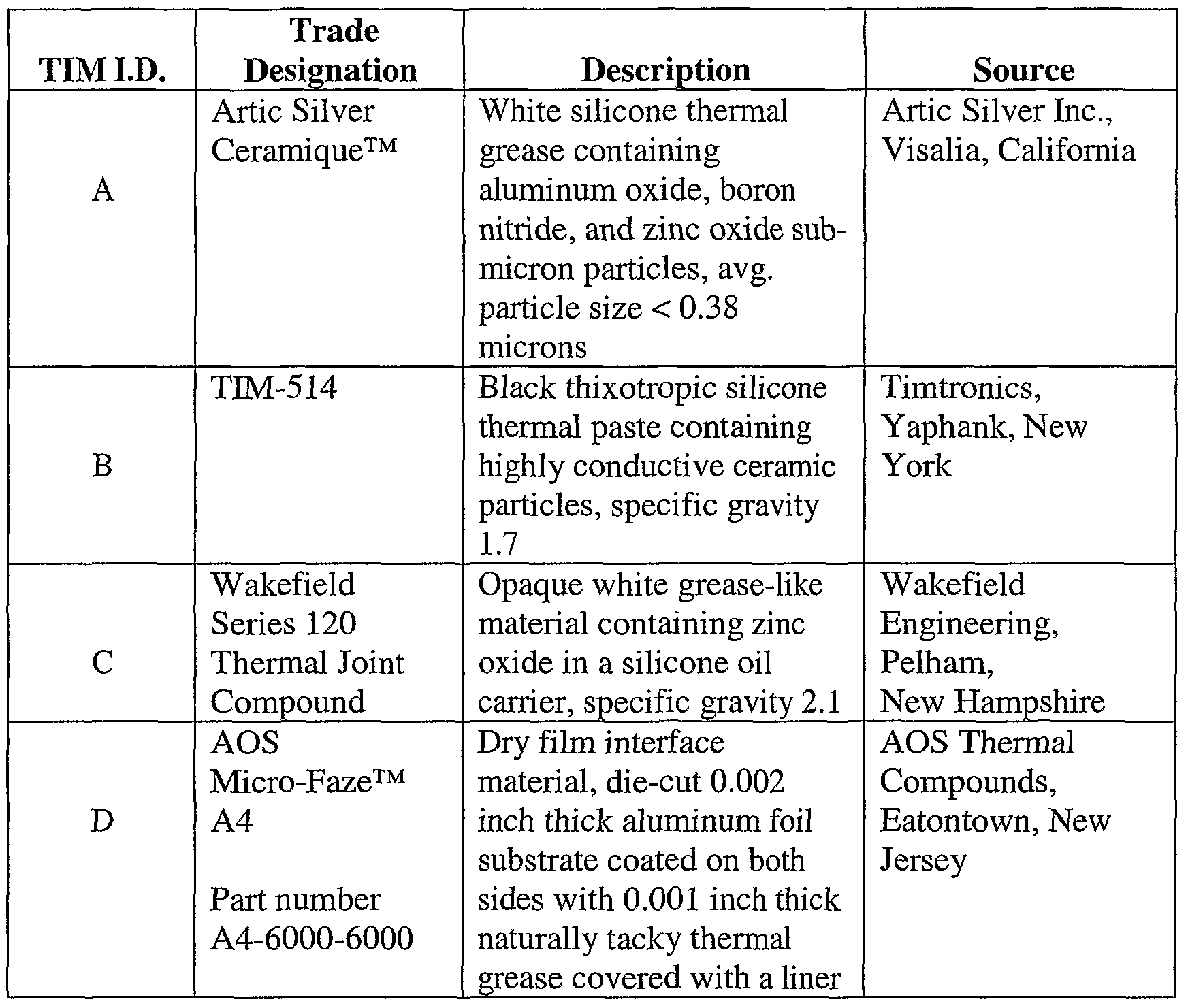
Certain commercially available materials were used in the Examples of the invention, as summarized in Table 1.
Table 1: Description of thermal interface materials.
Determination of Percent Filler Content
The weight percent filler loading of the liquid TIMs was measured as follows. An empty ceramic cup was weighed and the weight was recorded as Wl. Then, a quantity of liquid TM to be tested was added to the empty ceramic cup and the weight of the cup containing the TJJvI was recorded as W2. The cup containing the TJJVI was placed in a TEMCO Muffle Furnace, Model 1500, manufactured by Thermo Electric Mfg. CO., Dubuque, Iowa, and heated to about 540 °C for one hour to burn off the binder. The cup was removed from the oven and allowed to dwell at ambient temperature for about 35 minutes. Then the cup was weighed and the weight was recorded as W3. The weight percent filler content was calculated using Equation 3
Weight Percent Filler Content = [(W3-W1)/(W2-W1)] X 100. (3)
Table 2: Weight percent of filler in liquid thermal interface materials.
Example 1
A stencil, prepared by die cutting a 19 mm (0.75 inch) diameter circular opening in the center of a 76 micron (0.003 inch) thick polyester (PET) film, was taped onto the exposed surface of the heat sink so that the opening was approximately centered on the heat sink surface, and a dollop of liquid TIM C was placed into the opening. A metal spatula was used to squeegee-off the excess in a process commonly known as stenciling. The PET film was removed, leaving the grease in a 76 micron (0.003 inch) thick, 19 mm (0.75 inch) diameter circular layer on the heat sink.
In addition, a compliant material (Plastigauge Plastic Precision Clearance Gauge, available from Plastigauge Manufacturing Co, West Sussex, United Kingdom) was used to measure the thickness of the TLVI. A sample of the Plastigauge was placed on top of the stenciled TIM. As pressure was applied, the Plastigauge was compressed to the thickness of the gap between the heat sink and the copper block, that is, the thickness of the TEVI.
The thermal resistances of TIM C before and after sonication were determined according to the test method described above except that a Commtest MMS™ 3000 Series Data Logger temperature-logging instrument (manufactured by Commtest Instruments Ltd., Christchurch, New Zealand) was used in place of the Omega Model HH-22 Digital Thermometer. TCB and THS were measured every two seconds. The power was measured (a) at the start the test, (b) just before sonication, (c) just after sonication, and (d) at the termination of the test. The power varied slightly ranging from 98 to 102 Watts.
The lab jack was raised until an initial pressure of about 172 kPa (25 psi) was reached. Thermal resistances were calculated using Equation 2 and are shown in FIG. 3. Referring to FIG. 3, after achieving the initial pressure, the heater power supply was turned at point 300, and the thermal resistance rose to about 0.13 0CAV within ninty seconds, as shown by line 301. Within about 1000 seconds (approximately seventeen minutes), the thermal resistance declined to reach Initial Steady State at about 0.098 0CAV,
as shown by line 302. At approximately 1270 seconds (point 303), the fan was stopped and sonication was applied for about ten seconds. As shown by line 304, the thermal resistance rapidly dropped from about 0.095 °C/W to about 0.064 °C/W during the sonication. The fan was restarted, and the thermal resistance continued to decrease to a steady state value of about 0.056 0CAV, as shown by line 305.
At the end of the test, the thickness of the Plastigauge sample was about 48.3 microns (0.0019 inch). Thus, the TIM reduced in thickness from an initial thickness of 76 microns (0.003 inch) before sonication to about 48.3 microns after sonication.
Example 2
The thermal resistances of liquid TIM A before and after sonication were determined according to the test method described above. TIM A was applied as a dollop on the copper block and spread out into a thin film that covered the copper block surface. The lab jack was raised until an initial pressure of about 103 kPa (15 psi) was reached. Temperature data were collected periodically, and thermal resistances were calculated using Equation 2. Referring to FIG. 4, Initial Steady State was reached within about thirty minutes, as shown by line 401. Sonication was then applied for about four seconds. The reduction in thermal resistance after sonication is shown by line 402.
Example 3
A TIM composition was prepared by combining TIM B and about 33 wt% 15% Ag coated Cu particles in an open vessel with hand mixing until a uniform putty was obtained.
The silver-coated copper particles had an apparent density 2.4 g/cm^, a screen analysis (mesh) of 65% (325),and were obtained from Novamet Specialty Products Corporation,
Wyckoff, New Jersey The Determination of Percent Filler Content procedure was used to determine the final filler concentration. The data are reported in Table 2. The resulting composition contained about 95 wt% filler. A dollop of the putty was placed on the copper block. The thermal resistance of the TIM composition before and after sonication were determined according to the test method described above with the following exceptions: (a) after the first sonication, the pressure force was restored to the initial pressure force;
and (b) once steady state conditions were reached after restoring the pressure force in (a), the fan was turned off, a second sonication was applied, and the fan was turned back on.
The lab jack was raised until the initial pressure of about 103 kPa (15 psi) was reached. Referring to FIG. 5, Initial Steady State was reached within about 140 minutes, as shown by line 501. A first sonication was applied for about four seconds. The reduction in the thermal resistance of the TIM after the first sonication is shown by line 502. The lab jack was raised to restore the pressure to about 103 kPa (15 psi), as the pressure had dropped to about 56 kPa (8.2 psi) after the first sonication. This change in pressure is believed to have resulted from a decrease in the thickness of the layer of TEVI. Once steady state conditions were reached, a second sonication was applied for about four seconds. The reduction in the thermal resistance after the second sonication is shown by line 503.
Example 4 The thermal resistance of a commercially available thermally conductive film was determined before and after sonication according the test method described above. A tab of pressure sensitive adhesive (PSA) tape was applied to the release liner present on each side of a 2.5 cm (one inch) square piece of TM D film. The white release liner was removed by pulling on both tape tabs simultaneously. The sample was then placed on the copper block, pressed in place, and the remaining clear release liner was carefully removed without disturbing the TIM.
The lab jack was raised until an initial pressure of about 151 kPa (22 psi) was reached. Referring to FIG. 6, Initial Steady State was reached within about thirty-five minutes, as shown by line 601. Sonication was applied for about six seconds. The reduction in thermal resistance after sonication is by line 602.
Example 5
The effect of an additional step of heating a TBVI before sonication on the thermal resistance of a commercially available thermally conductive film was determined. The test apparatus set-up was as described above.
A sample of the TIM D film was prepared and applied to the copper block as described in Example 4. The TEVI was tested as described in Example 4 with the
following exceptions: (a) after Initial Steady State was reached and the cooling fan was turned off, the temperature of the copper block was allowed to climb until it reached 100 0C, after which the fan was turned on; and (b) after the first sonication step, steady state was reached, the fan was turned off, a second sonication of about four seconds was applied, and then the fan was turned on.
Referring to FIG. 7, the steady state thermal resistance before heating is shown by line 701 and the reduction in thermal resistance upon heating is shown by line 702. The reduction in thermal resistance achieved after the first sonication is shown by line 703, and the further reduction in thermal resistance achieved after the second sonication is shown by point 704. As shown in FIG. 7, a modest improvement in thermal performance resulted from the heat cycle, but a more substantial improvement in thermal performance resulted from the first sonication. The subsequent sonication demonstrated an additional improvement in thermal performance.
Example 6
The effect of an additional step of heating a TIM before applying the initial pressure on the thermal resistance of a commercially available thermally conductive film was determined. The Thermal Resistance test apparatus set up was as described above. A sample of the TBVI D film was prepared and applied to the copper block as described in Example 3. The TEVI was tested as described in Example 4 with the following exceptions: (a) the copper block was heated to 150 0C before an initial pressure of about 165 kPa (24 psi) was applied; (b) the first sonication lasted about ten seconds; and (c) after the first sonication steady state was reached, the fan was turned off, a second sonication lasting about ten seconds was applied, and then the fan was turned on. Referring to FIG. 8, the steady state thermal resistance after heating is shown by line 801. The reduction in thermal resistance achieved after the first sonication is shown by line 802, and the further reduction in thermal resistance achieved after the second sonication is shown by line 803. A substantial improvement in thermal performance resulting from the first sonication occurred even after pressing the TBVI in place at elevated temperature. The subsequent sonication demonstrated an additional improvement in performance.
Example 7
The effect of longer sonication on the thermal resistance of a commercially available thermally conductive film was determined. A sample of the TIM D film was prepared and mounted in the test bed as described in Example 4. Sonication was applied for about thirty seconds, as described in Example 4.
Referring to FIG. 9, the steady state thermal resistance prior to the extended sonication is shown by line 901. The reduction in thermal resistance achieved after the extended sonication is shown by line 902.
Example 8
A stencil, prepared by die cutting a 19 mm (0.75 inch) diameter circular opening in the center of a 76 micron (0.003 inch) thick polyester (PET) film, was taped onto the exposed surface of the heat sink so that the opening was about centered on the heat sink surface, and a dollop of liquid TIM C was placed into the opening. A metal spatula was used to squeegee-off the excess in a process commonly known as stenciling. The PET film was removed, leaving the grease in a 76 micron (0.003 inch) thick, 19 mm (0.75 inch) diameter circular layer on the heat sink.
The thermal resistances of TEVI C before and after sonication were determined according to the test method described above except that a Commtest MMS™ 3000 Series Data Logger temperature-logging instrument (manufactured by Commtest Instruments Ltd., Christchurch, New Zealand) was used in place of the Omega Model HH-22 Digital Thermometer. TCB and THS were measured every 30 seconds.
The lab jack was raised until an initial pressure of about 172 kPa (25 psi) was reached. Thermal resistances were calculated using Equation 2 and are shown in FIG. 10. Referring to FIG. 10, after achieving the initial pressure, the heater power supply was turned at point 1000, and the thermal resistance rose to about 0.079 0CAV within five minutes seconds, as shown by line 1001. Within about 25 minutes the thermal resistance declined to reach Initial Steady State at about 0.0740CAV, as shown by line 1002. The apparatus was held at steady state for approximately twenty hours (1205 minutes) at which point the thermal resistance had only decreased to about 0.071 0CAV. At the end of the approximately twenty hours (point 1003), the fan was stopped and sonication was applied for about four seconds. As shown by line 1004, the thermal resistance dropped from about
0.071 0CAV to about 0.0500CAV within the thirty seconds between temperature measurements during which the sonication occurred. The fan was restarted, and the thermal resistance continued to decrease to a steady state value of about 0.041 0CAV, as shown by line 1005.
Various modifications and alterations of this invention will become apparent to those skilled in the art without departing from the scope and spirit of this invention.