WO2006040407A1 - Method of determining pore characteristic, preparation method of sample unit, and sample unit - Google Patents

Method of determining pore characteristic, preparation method of sample unit, and sample unit Download PDF

Info

Publication number
WO2006040407A1
WO2006040407A1 PCT/FI2005/050353 FI2005050353W WO2006040407A1 WO 2006040407 A1 WO2006040407 A1 WO 2006040407A1 FI 2005050353 W FI2005050353 W FI 2005050353W WO 2006040407 A1 WO2006040407 A1 WO 2006040407A1
Authority
WO
WIPO (PCT)
Prior art keywords
medium
probe gas
sample
confined
phase
Prior art date
Legal status (The legal status is an assumption and is not a legal conclusion. Google has not performed a legal analysis and makes no representation as to the accuracy of the status listed.)
Ceased
Application number
PCT/FI2005/050353
Other languages
French (fr)
Inventor
Ville-Veikko Telkki
Juhani Lounila
Jukka Jokisaari
Current Assignee (The listed assignees may be inaccurate. Google has not performed a legal analysis and makes no representation or warranty as to the accuracy of the list.)
Individual
Original Assignee
Individual
Priority date (The priority date is an assumption and is not a legal conclusion. Google has not performed a legal analysis and makes no representation as to the accuracy of the date listed.)
Filing date
Publication date
Application filed by Individual filed Critical Individual
Priority to US11/665,132 priority Critical patent/US20070287184A1/en
Publication of WO2006040407A1 publication Critical patent/WO2006040407A1/en
Anticipated expiration legal-status Critical
Ceased legal-status Critical Current

Links

Classifications

    • GPHYSICS
    • G01MEASURING; TESTING
    • G01NINVESTIGATING OR ANALYSING MATERIALS BY DETERMINING THEIR CHEMICAL OR PHYSICAL PROPERTIES
    • G01N15/00Investigating characteristics of particles; Investigating permeability, pore-volume or surface-area of porous materials
    • G01N15/08Investigating permeability, pore-volume, or surface area of porous materials
    • GPHYSICS
    • G01MEASURING; TESTING
    • G01RMEASURING ELECTRIC VARIABLES; MEASURING MAGNETIC VARIABLES
    • G01R33/00Arrangements or instruments for measuring magnetic variables
    • G01R33/20Arrangements or instruments for measuring magnetic variables involving magnetic resonance
    • G01R33/44Arrangements or instruments for measuring magnetic variables involving magnetic resonance using nuclear magnetic resonance [NMR]
    • GPHYSICS
    • G01MEASURING; TESTING
    • G01NINVESTIGATING OR ANALYSING MATERIALS BY DETERMINING THEIR CHEMICAL OR PHYSICAL PROPERTIES
    • G01N24/00Investigating or analyzing materials by the use of nuclear magnetic resonance, electron paramagnetic resonance or other spin effects
    • G01N24/08Investigating or analyzing materials by the use of nuclear magnetic resonance, electron paramagnetic resonance or other spin effects by using nuclear magnetic resonance
    • G01N24/081Making measurements of geologic samples, e.g. measurements of moisture, pH, porosity, permeability, tortuosity or viscosity
    • YGENERAL TAGGING OF NEW TECHNOLOGICAL DEVELOPMENTS; GENERAL TAGGING OF CROSS-SECTIONAL TECHNOLOGIES SPANNING OVER SEVERAL SECTIONS OF THE IPC; TECHNICAL SUBJECTS COVERED BY FORMER USPC CROSS-REFERENCE ART COLLECTIONS [XRACs] AND DIGESTS
    • Y10TECHNICAL SUBJECTS COVERED BY FORMER USPC
    • Y10TTECHNICAL SUBJECTS COVERED BY FORMER US CLASSIFICATION
    • Y10T436/00Chemistry: analytical and immunological testing
    • Y10T436/24Nuclear magnetic resonance, electron spin resonance or other spin effects or mass spectrometry

Definitions

  • the invention relates to a method of determining a pore characteris- tic of a porous substance, a preparation method of preparing a sample for the determination of a pore characteristic of a porous substance with nuclear mag ⁇ netic resonance spectroscopy, and a sample unit for determining a pore char ⁇ acteristic of a porous substance with nuclear magnetic resonance spectros ⁇ copy.
  • Porous materials are typically solids with a large internal surface primarily due to the walls of interconnecting networks of pores and cavities.
  • the primary physical properties of porous materials are defined by pore char ⁇ acteristics, such as pore size, pore size distribution and pore volume.
  • pore char ⁇ acteristics such as pore size, pore size distribution and pore volume.
  • An object of the invention is to provide an improved method of de ⁇ termining a pore characteristic of a porous substance, an improved preparation method of preparing a sample for the determination of a pore characteristic of a porous substance with nuclear magnetic resonance spectroscopy, and an improved sample unit for determining a pore characteristic of a porous sub ⁇ stance with nuclear magnetic resonance spectroscopy.
  • a method of determining a pore charac ⁇ teristic of a porous substance including: subjecting a sample to an external magnetic field, the sample including the porous substance and a medium with a confined portion confined into the pores of the porous substance and a bulk portion surrounding at least a portion of the porous substance, the sample fur ⁇ ther including probe gas soluble to the medium and inert to the medium and to the porous substance and having a nuclear magnetic response to electromag- netic stimulation, the nuclear magnetic response depending on the magnetic environment of the probe gas, at least a portion of the probe gas being con ⁇ fined to the pores and being transferred into the pores as dissolved in the con ⁇ fined portion, the medium being selected to generate a magnetic environment for the probe gas confined to the pores that differs from the magnetic environ ⁇ ment of the probe gas dissolved in the bulk portion; applying electromagnetic stimulation to the sample, the electromagnetic stimulation being selected to induce at least one response signal in the probe gas; recording the
  • a preparation method of preparing a sample for the determination of a pore characteristic of a porous substance with nuclear magnetic resonance spec ⁇ troscopy including: placing the porous substance into an air-tight container; inserting liquid-phase medium into the air-tight container, thus producing a confined portion and a bulk portion of the medium, the confined portion being confined into the pores of the porous substance and the bulk portion surround ⁇ ing at least a portion of the porous substance, the medium being selected to generate a magnetic environment for the probe gas confined to the pores that differs from the magnetic environment of the probe gas dissolved in the bulk portion; and dissolving a quantity of the probe gas into the medium, the probe gas being inert to the medium and to the porous substance and having a nu ⁇ clear magnetic response to electromagnetic stimulation, the nuclear magnetic response depending on the magnetic environment of the probe gas, thus transferring at least a portion of the probe gas into the pores as dissolved in the confined portion.
  • a sample unit for determining a pore characteristic of a porous substance with nuclear magnetic resonance spectroscopy including: a porous substance; a medium including a confined portion confined into the pores of the porous sub ⁇ stance and a bulk portion surrounding at least a portion of the porous sub ⁇ stance; probe gas soluble to the medium and inert to the medium and to the porous substance and having a nuclear magnetic response to electromagnetic stimulation, the nuclear magnetic response depending on the magnetic envi- ronment of the probe gas, at least a portion of the probe gas being confined to the pores and being transferred into the pores as dissolved in the confined por- tion; and the medium being selected to generate a magnetic environment for the probe gas confined to the pores that differs from the magnetic environment of the probe gas dissolved in the bulk portion.
  • the invention provides several advantages.
  • the invention enables the determination of a pore characteristic, such as pore size, pore size distribu ⁇ tion, and/or pore volume, with a single NMR measurement carried out at one sample temperature, thus reducing the need to carry out a series of NMR measurements at different thermal conditions.
  • the use of the medium in ⁇ creases the sensitivity of the probe gas to the pore characteristic resulting in accurate determination of the pore characteristic.
  • Figure 2A illustrates an example of a sample unit
  • Figure 2B illustrates an example of a part of the sample unit
  • Figure 3 shows the phase behaviour of a medium
  • Figure 4A shows an example of a part of the sample at a first sam- pie temperature
  • Figure 4B shows an example of a part of the sample at a second sample temperature
  • Figure 4C shows an example of a part of the sample at a third sam ⁇ ple temperature
  • Figure 5 shows examples of NMR spectra at different sample tem ⁇ peratures
  • Figure 6 shows an example of a reference curve
  • Figure 7 shows an example of a methodology of preparing a sample unit according to the embodiments of the invention
  • Figure 8 shows an example of a methodology of determining a pore characteristic according to the embodiments of the invention.
  • the NMR apparatus 100 includes magnetizing units (M 1 , M2) 102, 104 and a sample unit 106 placed typically inside the magnetizing units 102, 104.
  • the magnetiz ⁇ ing units 102, 104 generate an external magnetic field 128 applied to the sam ⁇ ple unit 106, thus inducing a macroscopic magnetization of the NMR active nuclei of substances placed in the sample unit 106.
  • the magnetizing units 102, 104 may consist of a single super-conducting coil.
  • the NMR apparatus 100 further comprises stimulation means 108, 118 for providing an electromagnetic stimulation for the sample unit 106.
  • the stimulation means typically include a signal generator (SG) 108 and an induc ⁇ tion coil 118 placed in the vicinity of the sample unit 106.
  • the signal generator 108 generates an electric signal 120 including radio frequencies that corre ⁇ spond to the energy differences between spin states of the NMR active spins of the substances placed in the external magnetic field 128.
  • the induction coil 118 transforms the electric signal 120 into an electromagnetic field oscillating at the radio frequencies, thus resulting in an excitation of the NMR active spins in the sample unit 106 from lower energy levels to upper energy levels.
  • the NMR apparatus 100 further comprises detection means 110, 116 for detecting the response of the NMR active nuclei of the substance placed in the sample unit 106 to the electromagnetic stimulation provided by the stimulation means 108, 118.
  • the electromagnetic stimulation is also re- ferred to as magnetic stimulation, since it is the magnetic component of the electromagnetic field that plays the primary role in the stimulation.
  • the detec ⁇ tion means 110, 116 typically include a detection coil 116 placed in the vicinity of the sample unit 106. The detection coil 116 detects the internal magnetic field generated by the NMR active nuclei of the substance placed in the sam- pie unit 106 after the electromagnetic stimulation.
  • the detection coil 116 trans ⁇ forms the internal magnetic field into a response signal 122 that characterizes the spin energy levels of the NMR active nuclei of the substances placed in the sample unit 106.
  • the detection coil 116 may be connected to a detector unit 110 (DU) which processes the response signal 122, for example, by amplify- ing, filtering, and/or carrying out analogue-to-digital conversions.
  • the response signal 122 is also referred to as an NMR signal or an FID (Free Induction De ⁇ cay).
  • a plurality of NMR signals shown in a same scale is referred to as an NMR spectrum.
  • the NMR spectrum may be formed by combining different fre ⁇ quency components of the NMR signal measured at different time instants or by obtaining the different frequency components of the NMR signal in a single measurement or in a series of successive measurements.
  • the response signal 122 is presented in a chemical shift scale that characterizes the frequency content of the response signal 122 in relation to a known reference, such as tetramethyl silane (TMS).
  • TMS tetramethyl silane
  • the induction coil 118 and the detection coil 116 are integrated into a single coil structure. In such a case, a switch ar ⁇ rangement is applied to separate the stimulation means 108, 118 from the de ⁇ tection means 110, 116.
  • the NMR apparatus 100 may further include a recording unit (RU)
  • the NMR apparatus 100 may further include a processing unit 114 connected to the recording unit 112.
  • the processing unit 114 may perform tasks, such as a Fourier transformation of the digital response signal 126, summation of a plurality of digital response signals 126, and generation of con ⁇ trol signals 130 that control the signal generator 108.
  • the sample unit 200 includes an air ⁇ tight container 202, such as a glass tube, suitable for depressurization and placement into a sample compartment of the NMR apparatus 100.
  • an air ⁇ tight container 202 such as a glass tube
  • a porous substance is put into the container 200.
  • impurities such as residual water, are removed from the sample unit 200 by depressurizing the container 202 with a vacuum system 220 connected to the container 202.
  • the container 202 may be isolated from the vacuum sys- tern 220 after the sample preparation with an air-tight cap 204 or by melting a part of the container 200 in order to sealing the neck of the container 200.
  • the sample unit 200 further includes a liquid-phase medium in ⁇ serted into the container 202.
  • the medium is typically introduced into the con- tainer 202 such that the surface of the medium remains on the top of the coil region 218 of the NMR apparatus 100.
  • the medium provides a bath for the porous substance and penetrates into the pores of the porous substance. As a result, a portion of the medium is confined to the pores.
  • the portion of the me ⁇ dium confined to the pores is also referred to as the confined medium.
  • the porous substance is typically a powder-like material in order to improve access to the pores and to ease the penetration of the medium into the pores.
  • the particle size of a porous substance powder may fall into mi ⁇ crometer region. In some embodiments, the diameter of the particles varies from 10 to 200 ⁇ m. The particle size is not, however, restricted to the given figures.
  • a portion of the medium surrounds the porous substance.
  • the por ⁇ tion of the medium surrounding the porous substance and excluding the con ⁇ fined medium is also referred to as the bulk medium.
  • the mixture of the porous substance and the medium typically form a measurement layer 210 of the sample.
  • the height of the measurement layer 210 is typically in the centimetre range, varying from 1 to 3 cm, for example.
  • the height of the measurement layer 210 is not, however, restricted to the given figures, but depends on external factors, such as the coil structure of the NMR apparatus 100.
  • the excess medium 208 above the measurement layer 210 forms a medium layer 208.
  • the measurement layer 210 is primarily subjected to NMR measurement when determining a pore characteristic of the porous substance.
  • Figure 2B shows an example of the structure of the measurement layer 210.
  • the porous substance is presented by particles 212A, 212B having pores 214A, 214B that confine the confined medium 222.
  • the bulk medium 216 surrounds the particles 212A, 212B.
  • a quantity of probe gas is dissolved into the medium by introducing pressurized probe gas into the sam ⁇ ple unit 200.
  • the vacuum system 220 may have a suitable valve arrangement and a manometer in order to control the flow to the container 202 and the quantity of the pressurized probe gas in the container 202.
  • the pressure ap ⁇ plied to the probe gas in the ambient temperature may vary from 1 to 4 atmos ⁇ pheres.
  • the present solution is not, however, restricted to these pressure val ⁇ ues but the value may be chosen according to probe gas characteristics and medium characteristics.
  • the quantity of the probe gas in ⁇ troduced into the container 202 is recorded in order to scale the results ob- tained from the NMR measurement with a known reference.
  • the known refer ⁇ ence may be a sample unit similar to the sample unit 202 applied in an actual determination and including a porous substance with known pore characteris ⁇ tics.
  • the introduction of the probe gas into the container 202 is typically preceded by the cooling of the sample unit 200 to a low temperature with, for example, liquid nitrogen.
  • the quantity of the probe gas introduced into the container 202 may be calculated from the volume of the container 202, the pressure of the probe gas buffered into the feeding line of the vacuum sys- tern 220, and the volume of the feeding line of the vacuum system 220.
  • the excess probe gas typically forms a probe gas layer 206 in the sample unit 200.
  • a portion of the probe gas is transferred into the pores 214A, 214B as dissolved in the confined medium 222.
  • a portion of the probe gas is dissolved in the bulk medium 216.
  • the probe gas is typically inert to the medium and to the porous substance in order to leave the sample chemically stable during the sample preparation and the determination of the pore characteristic.
  • the probe gas has a nuclear magnetic response to electromagnetic stimulation, which magnetic response depends on the magnetic environment of the probe gas. The nuclear magnetic response may be observed from the response sig ⁇ nal 122 generated in the sample unit 106 as a result of the electromagnetic stimulation generated by the stimulation means 108, 1 18.
  • the magnetic environment typically includes an intrinsic magnetic environment arising from intra-atomic/intramolecular mechanisms, and an ex ⁇ ternal magnetic environment generated by the surroundings of the probe gas atoms/molecules.
  • the external magnetic environment may be caused by the medium in which the probe gas is dissolved and possibly by the free space surrounding the probe gas atoms/molecules.
  • the medium is selected so that a magnetic environment is gener ⁇ ated for the probe gas confined to the pores 214A, 214B that differs from the magnetic environment of the probe gas dissolved in the bulk medium 216.
  • the different magnetic environments in the pores 214A, 214B and in the bulk me- dium 216 result in frequency characteristics of the response signal 122 being generated in the pores 214A, 214B that differs from frequency characteristics being generated in the bulk medium 216.
  • the bulk medium 216 experiences virtually an unaffected environment in the molecular scale while the pores 214A, 214B affect the physical characteristics of the con ⁇ fined medium 222 such that the probe gas confined to the pores 214A, 214B experiences an influenced magnetic environment.
  • the influence of the pores 214A, 214B on the confined medium 222 depends on a pore characteristic, such as the size, of the pore 214A, 214B, and consequently, the response signal 122 generated in the probe gas con ⁇ fined to the pore 214A, 214B carries information of the pore characteristic in the frequency content of the response signal 122.
  • a porous substance includes a plurality of pores 214A, 214B with dif- ferent pore characteristics, and the response signal 122 is contributed by a spectrum element characterizing each pore 214A, 214B.
  • the re ⁇ sponse signal 122 includes a frequency distribution that characterizes the pore characteristic distribution of the sample.
  • the medium is condensed fluid, such as liquid, the medium being selected to provide a magnetic environment for the probe gas dissolved in the confined medium 222 that differs from the magnetic environment for the probe gas dissolved in the bulk medium 216.
  • a response signal 122 is generated in the probe gas dissolved in the confined medium 222 that differs from a response signal 122 generated in the bulk medium 216 when the electromagnetic stimulation is applied to the sam- pie.
  • the confined medium 222 and the bulk medium 216 are a liq ⁇ uid-state material or liquid crystal.
  • the pore 214A, 214B affects the confined medium 222 through interaction mechanisms, such as a surface tension mechanism, such that the probe gas dissolved in the confined medium 222 experiences a magnetic environment characteristic to the pore 214A, 214B.
  • interaction mechanisms such as a surface tension mechanism
  • electromagnetic stimulation is applied to the sample, a response signal characteristic to the pore 214A, 214B is generated.
  • the medium may be acetonitrile or naphthalene, for example.
  • the invention is not, however, restricted to acetonitrile and naphthalene, but any chemical substance filling the physical and chemical requirements of the me ⁇ dium may be used. Such requirements are, for example, low chemical reactiv- ity with the porous material and a feasible solidification temperature, such as that close to the ambient temperature.
  • the medium is a liquid crystal and selected to have an isotropic phase in the confined medium 222 and an anisotropic phase in the bulk medium 216 at a measurement temperature.
  • the liquid crystal is a thermotropic liquid crystal, for example.
  • the medium is selected to have a lower phase- transition temperature in the confined medium 222 than the phase-transition temperature in the bulk medium 216. The phase transition occurs between the liquid phase and the solid phase.
  • the medium is further selected to have a larger density in the solid phase than the density in the liq ⁇ uid phase.
  • phase behaviour of the medium is shown as a function of a sample temperature.
  • the horizontal axis 300 repre ⁇ sents time in arbitrary units, such as hours, while the vertical axis 302 shows the sample temperature in arbitrary units, such as Kelvin.
  • both the bulk medium 216 and the confined medium 222 are in the liquid state.
  • the sample temperature is decreased to a first phase-transition temperature 312 Ti, the phase transition of the bulk medium 216 from the liquid state to the solid state takes place, while the confined medium 222 remains in the liquid phase.
  • the sample temperature is further decreased from the first phase-transition temperature 312 Ti to a second phase-transition temperature 314 T 2 .
  • the bulk medium 216 remains solid and the confined medium 222 remains liquid.
  • a phase transition in the confined medium 222 takes place from the liquid state to the solid state.
  • both the bulk medium 216 and the confined medium 222 appear in the solid state.
  • the difference AT D in the phase-transition temperatures between the solid phase and the liquid phase in the bulk medium 216 and in the confined medium 222 may be expressed with the Gibbs- Thompson equation
  • T B and T c are the phase-transition temperatures of the bulk medium 216 and confined medium 222, respectively
  • k p is a constant characterizing the medium
  • i ⁇ is a pore radius of a pore 214A, 214B.
  • the pore characteristics may vary between the pores 214A, 214B, and the first phase-transition temperature 312 Ti and the second phase-transition temperature 314 T 2 should be understood as average temperatures or other temperature measures that characterize the temperature behaviour of the me ⁇ dium in a plurality of pores 214A, 214B.
  • Figure 5 shows an example of NMR spectra 506 to 512 of the sam ⁇ ple during sample temperature evolution from the first phase-transition tem ⁇ perature 312 Ti to the second phase-transition temperature 314 T 2 shown in Figure 3.
  • the horizontal axis 500 shows a chemical shift in arbitrary units, such as ppm (parts per million), while the vertical axis 502 shows the spectrum in- tensity in arbitrary units, such as power units.
  • the reference point 504 corre ⁇ sponding to a zero chemical shift is labelled with a vertical bar and the value of the chemical shift increases to the left from the reference point 504.
  • the NMR spectra 506 to 512 may be obtained by applying the elec ⁇ tromagnetic stimulation including radio frequencies corresponding to the chemical shifts expected to appear in the spectra 506 to 512.
  • an appropriate frequency content of the electromagnetic stimulation is achieved by subjecting the sample unit 106 to a short electromagnetic pulse generated by the stimulation means 108, 118. In this case, the required spec ⁇ trum range is measured at once.
  • the quality of the spectrum 506 to 512 may be improved by repeating the pulse and by co-adding the spectrum compo ⁇ nents.
  • the response signal 122 is detected by the detecting means 110, 116 and the digital response signal 124 is taken to the recording unit 112.
  • the recording unit 112 may store the spectrum components and co-add the spec ⁇ trum components in order to generate a sum spectrum 506 to 512.
  • Figure 4A illustrates the bulk medium 404 surrounding a particle 408 of the porous substance and the confined medium 402 confined in a pore 400 of the particle 408 during the first time period 306.
  • the bulk me- dium 404 and the confined medium 402 are in the liquid state, and the probe gas dissolved in the medium may freely access the pore 400 by normal physi ⁇ cal mechanisms, such as those driven by thermal effects.
  • the probe gas dis ⁇ solved in the medium is represented by black dots.
  • the first NMR spectrum 506 in Figure 5 represents an example of an NMR spectrum recorded during the first time period 306.
  • the first NMR spectrum 506 may include a first signal (C) 514 and a second signal (B) 516 originating from probe gas dissolved in the liquid-state medium.
  • the first signal 514 originates from the probe gas dissolved in the confined medium 402 that is in the liquid state.
  • the second signal 516 originates from the probe gas dis- solved in the bulk medium 404 that is in the liquid state.
  • the first signal 514 and the second signal 516 provide pore charac ⁇ teristics, such as an average pore size and a pore size distribution.
  • the aver ⁇ age pore size may be obtained from the center-of-mass of the first signal 514 while the pore size distribution may be obtained from the shape of the first sig- nal 514.
  • the first signal 514 provides a pore volume characteriz ⁇ ing the integrated volume of the pores 214A, 214B in the sample.
  • the pore volume may be obtained by taking an integral over the first signal 514.
  • the pore radius R p of a pore is obtained from formula
  • ⁇ c and ⁇ B are the chemical shifts of the first signal 514 and second signal 516, respectively.
  • Parameters a, b, c, and d are fitting parameters ob ⁇ tained for reference samples.
  • Figure 4B illustrates the bulk medium 404 and the confined medium 402 during the second time interval 308.
  • the bulk medium 404 primarily is in the solid state providing a shield around the particle 408 and re ⁇ ducing the medium and the probe gas either entering or exiting the pore 400.
  • the confined medium 402 primarily is in the liquid state.
  • a second and third NMR spectra 508 and 510 represent an example of NMR spectra recorded during the second time interval 308.
  • the second NMR spectrum 508 is recorded at a higher temperature than the temperature applied to the third NMR spectrum 510.
  • the second signal 516 has weakened as the phase transition from the liquid state to the solid state in the bulk me- dium 404 has started.
  • the first signal 514 can still be identified as the confined medium 402 is primarily in the liquid state. However, at this stage, the solidifi ⁇ cation in the confined medium 402 confined to the largest pores has started, thus giving rise to an appearance of a third signal (D) 520.
  • the second signal 516 does not oc- cur due to the solidification of the bulk medium 404.
  • the first signal 514 has weakened and the third signal 520 has gained strength.
  • Figure 4C illustrates the bulk medium 404 and the confined medium 402 during the third time interval 310.
  • the bulk medium 404 is in the solid state, thus reducing the exchange of the medium and the probe gas between the pore 400 and the surroundings of the particle 408.
  • the con ⁇ fined medium 402 is in the solid state, and due to the larger density in the solid state than in the liquid state, gas pockets 406 have been created as a result of shrinkage of the confined medium 402. For this reason, different magnetic en ⁇ vironments have been created between the probe gas confined in the pore 400 and the probe gas dissolved in the bulk medium 404.
  • the fourth NMR spectrum 512 represents an example of an NMR spectrum recorded during the third time interval 310.
  • the first sig ⁇ nal 514 is relatively weak and indicates a residual of a liquid-phase confined medium 402 in some of the pores 400.
  • the third signal 520 has further gained strength due to the increased volume of the gas pockets 406.
  • the probe gas and the medium are selected to have a higher solubility of the probe gas to the medium in the liquid state than the solubility of the probe gas to the medium in the solid state.
  • the higher solubility in the liquid state increases the quantity of the probe gas being introduced in the gas pockets 406 when the confined medium 402 trans ⁇ forms from the liquid state to the solid state.
  • the increase in the quantity of the probe gas in the gas pockets improves the sensitivity of the NMR measure ⁇ ment to the phase transition, thus improving the accuracy of the determination of the pore characteristic.
  • the perturbation due to the interaction of a probe gas atom with its surroundings in the gas pockets 406 lowers the magnetic shielding ⁇ of the probe nuclei.
  • the size of the pocket 406 is proportional to the size of the pore 402, the chemical shift of the third signal 520 decreases with increasing pore size.
  • the relation between the pore radius R p and chemical shift ⁇ of the third signal 520 is expressed as
  • FIG. 6 illustrates graphically Eq. (3).
  • the horizontal axis 600 shows the chemical shift while the vertical axis 602 shows the pore radius.
  • the least squares parameters a, b, c, and d and Eq. (3) define a reference curve 606 that may be obtained by determining the chemical shift 608 of the third signal 520 for a porous substance with known pore size characteristics.
  • calibration points 604A, 604B, 604C have been determined and a least- squares fit has been carried out by using Eq. (3).
  • the pore radius R s of a sam ⁇ ple with unknown pore characteristics may be obtained by determining the chemical shift ⁇ s of the third signal 520 and by using Eq. (3).
  • Figures 3, 4A, 4B, 4C, and 5 illustrate an example of a sample his- tory.
  • the sample is typically prepared within the temperature limits defined by the first time period 306 since both the bulk medium 404 and the confined me ⁇ dium 402 are in the liquid state.
  • the direction of the time evolution is not, how ⁇ ever, critical to the present solution, as long as the sample unit 106, 200 has experienced the first time period 306, i.e. a stage when both the bulk medium 404 and the confined medium 402 occur in the liquid state in order to enable the probe gas to access the pores 400.
  • the actual measurement temperature at which the determination of the pore characteristics is carried out may be selected relatively freely. However, the measurement temperature may be fixed at a value depending on factors, such as the temperature of the reference measurement, characteristics of the medium, and pore characteristics to be determined.
  • a plurality of NMR measure ⁇ ments are carried out at sample temperatures between the first sample tem- perature and the second sample temperature, thus producing a trend of re ⁇ sponse signals as a function of the sample temperature.
  • the first sample tem ⁇ perature and the second sample temperature correspond to the first transition temperature 312 and the second transition temperature 314, respectively.
  • the NMR measurements result in NMR spectra similar to NMR spectra 506 to 512.
  • the trend of the response signals may be monitored by determining the strength of the NMR signals 514, 516, 520.
  • the trend of the third signal 520 is recorded and the solidification temperature of the confined medium 402 is determined from the trend.
  • the third signal 520 vanishes.
  • the pore radius R p may then be obtained from Eq. (1 ) where the solidification temperature of the bulk medium 404 may be taken from literature or from the trend of the second signal 516.
  • the sample temperature is in ⁇ creased between successive measurements in order to avoid supercooling effects of the sample. After each measurement, the sample may be allowed to stabilize.
  • the sample temperature may be monitored by measuring directly the sample temperature in the sample unit 106, 200.
  • the sample unit 106, 200 includes a capillary tube including an NMR active chemi- cal giving an NMR signal which is sensitive to temperature.
  • the actual tem ⁇ perature may be determined from the chemical shift of the signal generated from the chemical and from a calibration curve.
  • the porous substance is placed into an air-tight container 202.
  • a liquid-phase medium is inserted into the air-tight container 202, thus producing a confined portion 222 and a bulk portion 216 of the me ⁇ dium, the confined portion 222 being confined into the pores 214A, 214B of the porous substance and the bulk portion 216 surrounding at least a portion of the porous substance, the medium being selected to generate a magnetic envi ⁇ ronment for probe gas confined to the pores 214A, 214B that differs from the magnetic environment of the probe gas dissolved in the bulk portion 216.
  • a quantity of probe gas is dissolved into the medium, the probe gas being inert to the medium and to the porous substance and having a nuclear magnetic response to electromagnetic stimulation, the nuclear mag ⁇ netic response depending on the magnetic environment of the probe gas, thus transferring at least a portion of the probe gas into the pores as dissolved in the confined portion 222.
  • the air-tight container 202 is sealed. In 710, the method ends.
  • the measurement temperature is adjusted.
  • a sample is subjected to an external magnetic field 128, the sample including the porous substance and a medium with a confined portion 222 confined into the pores of the porous substance and a bulk portion 216 surrounding at least a portion of the porous substance, the sample further in ⁇ cluding probe gas soluble to the medium and inert to the medium and to the porous substance and having a nuclear magnetic response to electromagnetic stimulation, the nuclear magnetic response depending on the magnetic envi ⁇ ronment of the probe gas, at least a portion of the probe gas being confined to the pores 214A, 214B and being transferred into the pores as dissolved in the confined portion 222, the medium being selected to generate a different mag ⁇ netic environment for the probe gas confined to the pores 214A, 214B from the magnetic environment of the probe gas dissolved in the bulk portion 216.
  • electromagnetic stimulation is applied to the sample, the electromagnetic stimulation being selected to induce at least one response signal 122 in the probe gas.
  • the electro ⁇ magnetic stimulation is selected to induce a first response signal 514 in the probe gas dissolved in the confined portion 402 and second response signal 516 in the probe gas dissolved in the bulk portion 404.
  • the at least one response signal is recorded.
  • the first response signal 514 and the second response signal 516 are recorded.
  • the pore characteristic is determined from the at least one response signal 122 in 812.
  • the pore characteristic is determined from the first re- sponse signal 514 and the second response signal 516.

Landscapes

  • Physics & Mathematics (AREA)
  • General Physics & Mathematics (AREA)
  • Chemical & Material Sciences (AREA)
  • Health & Medical Sciences (AREA)
  • Condensed Matter Physics & Semiconductors (AREA)
  • Dispersion Chemistry (AREA)
  • High Energy & Nuclear Physics (AREA)
  • Life Sciences & Earth Sciences (AREA)
  • Analytical Chemistry (AREA)
  • Biochemistry (AREA)
  • General Health & Medical Sciences (AREA)
  • Immunology (AREA)
  • Pathology (AREA)
  • Measuring Or Testing Involving Enzymes Or Micro-Organisms (AREA)
  • Other Investigation Or Analysis Of Materials By Electrical Means (AREA)

Abstract

A method of determining a pore characteristic, a method of preparing a sample unit, and a sample unit are provided. In the method of determining, a sample is subjected to an external magnetic field, the sample including a porous substance and a medium including a confined portion confined into the pores of the porous substance and a bulk portion surrounding at least a portion of the porous substance, the sample further including probe gas soluble to the medium and inert to the medium and to the porous substance and having a nuclear magnetic response to electromagnetic stimulation, the nuclear magnetic response depending on the magnetic environment of the probe gas, at least a portion of the probe gas being confined to the pores and being transferred into the pores as dissolved in the confined portion, the medium being selected to generate a magnetic environment for the probe gas confined to the pores that differs from the magnetic environment of the probe gas dissolved in the bulk portion; electromagnetic stimulation is applied to the sample, the electromagnetic stimulation being selected to induce at least one response signal in the probe gas; the at least one response signal is recorded; and the pore characteristic is determined from the at least one response signal.

Description

Method of determining pore characteristic, preparation method of sample unit, and sample unit
Field
The invention relates to a method of determining a pore characteris- tic of a porous substance, a preparation method of preparing a sample for the determination of a pore characteristic of a porous substance with nuclear mag¬ netic resonance spectroscopy, and a sample unit for determining a pore char¬ acteristic of a porous substance with nuclear magnetic resonance spectros¬ copy.
Background
Porous materials are typically solids with a large internal surface primarily due to the walls of interconnecting networks of pores and cavities. The primary physical properties of porous materials are defined by pore char¬ acteristics, such as pore size, pore size distribution and pore volume. Prior art suggests various techniques, such as gas adsorption NMR
(Nuclear Magnetic Resonance) cryoporometry, mercury porosiometry, and NMR relaxometry, for determining pore characteristics. However, the prior art techniques are either inaccurate and/or require a complex and time-consuming measurement procedure. Therefore, there is a need to consider alternatives for determining pore characteristics of porous materials.
Brief description of the invention
An object of the invention is to provide an improved method of de¬ termining a pore characteristic of a porous substance, an improved preparation method of preparing a sample for the determination of a pore characteristic of a porous substance with nuclear magnetic resonance spectroscopy, and an improved sample unit for determining a pore characteristic of a porous sub¬ stance with nuclear magnetic resonance spectroscopy. According to a first as¬ pect of the invention, there is provided a method of determining a pore charac¬ teristic of a porous substance, including: subjecting a sample to an external magnetic field, the sample including the porous substance and a medium with a confined portion confined into the pores of the porous substance and a bulk portion surrounding at least a portion of the porous substance, the sample fur¬ ther including probe gas soluble to the medium and inert to the medium and to the porous substance and having a nuclear magnetic response to electromag- netic stimulation, the nuclear magnetic response depending on the magnetic environment of the probe gas, at least a portion of the probe gas being con¬ fined to the pores and being transferred into the pores as dissolved in the con¬ fined portion, the medium being selected to generate a magnetic environment for the probe gas confined to the pores that differs from the magnetic environ¬ ment of the probe gas dissolved in the bulk portion; applying electromagnetic stimulation to the sample, the electromagnetic stimulation being selected to induce at least one response signal in the probe gas; recording the at least one response signal; and determining the pore characteristic from the at least one response signal.
According to a second aspect of the invention, there is provided a preparation method of preparing a sample for the determination of a pore characteristic of a porous substance with nuclear magnetic resonance spec¬ troscopy, including: placing the porous substance into an air-tight container; inserting liquid-phase medium into the air-tight container, thus producing a confined portion and a bulk portion of the medium, the confined portion being confined into the pores of the porous substance and the bulk portion surround¬ ing at least a portion of the porous substance, the medium being selected to generate a magnetic environment for the probe gas confined to the pores that differs from the magnetic environment of the probe gas dissolved in the bulk portion; and dissolving a quantity of the probe gas into the medium, the probe gas being inert to the medium and to the porous substance and having a nu¬ clear magnetic response to electromagnetic stimulation, the nuclear magnetic response depending on the magnetic environment of the probe gas, thus transferring at least a portion of the probe gas into the pores as dissolved in the confined portion.
According to another aspect of the invention, there is provided a sample unit for determining a pore characteristic of a porous substance with nuclear magnetic resonance spectroscopy, including: a porous substance; a medium including a confined portion confined into the pores of the porous sub¬ stance and a bulk portion surrounding at least a portion of the porous sub¬ stance; probe gas soluble to the medium and inert to the medium and to the porous substance and having a nuclear magnetic response to electromagnetic stimulation, the nuclear magnetic response depending on the magnetic envi- ronment of the probe gas, at least a portion of the probe gas being confined to the pores and being transferred into the pores as dissolved in the confined por- tion; and the medium being selected to generate a magnetic environment for the probe gas confined to the pores that differs from the magnetic environment of the probe gas dissolved in the bulk portion.
The invention provides several advantages. The invention enables the determination of a pore characteristic, such as pore size, pore size distribu¬ tion, and/or pore volume, with a single NMR measurement carried out at one sample temperature, thus reducing the need to carry out a series of NMR measurements at different thermal conditions. The use of the medium in¬ creases the sensitivity of the probe gas to the pore characteristic resulting in accurate determination of the pore characteristic.
List of drawings
In the following, the invention will be described in greater detail with reference to embodiments of the invention and the accompanying drawings, in which Figure 1 shows an example of the structure of an NMR apparatus;
Figure 2A illustrates an example of a sample unit;
Figure 2B illustrates an example of a part of the sample unit;
Figure 3 shows the phase behaviour of a medium;
Figure 4A shows an example of a part of the sample at a first sam- pie temperature;
Figure 4B shows an example of a part of the sample at a second sample temperature;
Figure 4C shows an example of a part of the sample at a third sam¬ ple temperature; Figure 5 shows examples of NMR spectra at different sample tem¬ peratures;
Figure 6 shows an example of a reference curve;
Figure 7 shows an example of a methodology of preparing a sample unit according to the embodiments of the invention; and Figure 8 shows an example of a methodology of determining a pore characteristic according to the embodiments of the invention.
Description of embodiments
With reference to Figure 1 , an example of an NMR (Nuclear Mag¬ netic Resonance) apparatus 100 for NMR measurements is shown. The NMR apparatus 100 includes magnetizing units (M 1 , M2) 102, 104 and a sample unit 106 placed typically inside the magnetizing units 102, 104. The magnetiz¬ ing units 102, 104 generate an external magnetic field 128 applied to the sam¬ ple unit 106, thus inducing a macroscopic magnetization of the NMR active nuclei of substances placed in the sample unit 106. In some applications, the magnetizing units 102, 104 may consist of a single super-conducting coil.
The NMR apparatus 100 further comprises stimulation means 108, 118 for providing an electromagnetic stimulation for the sample unit 106. The stimulation means typically include a signal generator (SG) 108 and an induc¬ tion coil 118 placed in the vicinity of the sample unit 106. The signal generator 108 generates an electric signal 120 including radio frequencies that corre¬ spond to the energy differences between spin states of the NMR active spins of the substances placed in the external magnetic field 128. The induction coil 118 transforms the electric signal 120 into an electromagnetic field oscillating at the radio frequencies, thus resulting in an excitation of the NMR active spins in the sample unit 106 from lower energy levels to upper energy levels.
The NMR apparatus 100 further comprises detection means 110, 116 for detecting the response of the NMR active nuclei of the substance placed in the sample unit 106 to the electromagnetic stimulation provided by the stimulation means 108, 118. The electromagnetic stimulation is also re- ferred to as magnetic stimulation, since it is the magnetic component of the electromagnetic field that plays the primary role in the stimulation. The detec¬ tion means 110, 116 typically include a detection coil 116 placed in the vicinity of the sample unit 106. The detection coil 116 detects the internal magnetic field generated by the NMR active nuclei of the substance placed in the sam- pie unit 106 after the electromagnetic stimulation. The detection coil 116 trans¬ forms the internal magnetic field into a response signal 122 that characterizes the spin energy levels of the NMR active nuclei of the substances placed in the sample unit 106. The detection coil 116 may be connected to a detector unit 110 (DU) which processes the response signal 122, for example, by amplify- ing, filtering, and/or carrying out analogue-to-digital conversions. The response signal 122 is also referred to as an NMR signal or an FID (Free Induction De¬ cay). A plurality of NMR signals shown in a same scale is referred to as an NMR spectrum. The NMR spectrum may be formed by combining different fre¬ quency components of the NMR signal measured at different time instants or by obtaining the different frequency components of the NMR signal in a single measurement or in a series of successive measurements. In some embodiments, it is customary to present the response sig¬ nal 122 in the frequency domain. In such a case, the response signal 122 is presented in a chemical shift scale that characterizes the frequency content of the response signal 122 in relation to a known reference, such as tetramethyl silane (TMS).
In some embodiments, the induction coil 118 and the detection coil 116 are integrated into a single coil structure. In such a case, a switch ar¬ rangement is applied to separate the stimulation means 108, 118 from the de¬ tection means 110, 116. The NMR apparatus 100 may further include a recording unit (RU)
112 for recording a digital response signal 124 into a mass memory for later use.
The NMR apparatus 100 may further include a processing unit 114 connected to the recording unit 112. The processing unit 114 may perform tasks, such as a Fourier transformation of the digital response signal 126, summation of a plurality of digital response signals 126, and generation of con¬ trol signals 130 that control the signal generator 108.
With reference to Figure 2A, the sample unit 200 includes an air¬ tight container 202, such as a glass tube, suitable for depressurization and placement into a sample compartment of the NMR apparatus 100. In a sample preparation stage, a porous substance is put into the container 200. Further¬ more, impurities, such as residual water, are removed from the sample unit 200 by depressurizing the container 202 with a vacuum system 220 connected to the container 202. The container 202 may be isolated from the vacuum sys- tern 220 after the sample preparation with an air-tight cap 204 or by melting a part of the container 200 in order to sealing the neck of the container 200.
The structure and operation of the vacuum system 220 and the methods of transferring gaseous substances in the vacuum system 220 into the container 200 and isolating the container 200 from atmospheric pressure after sample preparation are known to a person skilled in NMR sample prepa¬ ration. Therefore, only details relevant to the present solution are discussed in this context.
The sample unit 200 further includes a liquid-phase medium in¬ serted into the container 202. The medium is typically introduced into the con- tainer 202 such that the surface of the medium remains on the top of the coil region 218 of the NMR apparatus 100. The medium provides a bath for the porous substance and penetrates into the pores of the porous substance. As a result, a portion of the medium is confined to the pores. The portion of the me¬ dium confined to the pores is also referred to as the confined medium.
The porous substance is typically a powder-like material in order to improve access to the pores and to ease the penetration of the medium into the pores. The particle size of a porous substance powder may fall into mi¬ crometer region. In some embodiments, the diameter of the particles varies from 10 to 200 μm. The particle size is not, however, restricted to the given figures. A portion of the medium surrounds the porous substance. The por¬ tion of the medium surrounding the porous substance and excluding the con¬ fined medium is also referred to as the bulk medium.
The mixture of the porous substance and the medium typically form a measurement layer 210 of the sample. The height of the measurement layer 210 is typically in the centimetre range, varying from 1 to 3 cm, for example. The height of the measurement layer 210 is not, however, restricted to the given figures, but depends on external factors, such as the coil structure of the NMR apparatus 100.
The excess medium 208 above the measurement layer 210 forms a medium layer 208. The measurement layer 210 is primarily subjected to NMR measurement when determining a pore characteristic of the porous substance.
Figure 2B shows an example of the structure of the measurement layer 210. The porous substance is presented by particles 212A, 212B having pores 214A, 214B that confine the confined medium 222. The bulk medium 216 surrounds the particles 212A, 212B.
In the preparation of the sample unit 200, a quantity of probe gas is dissolved into the medium by introducing pressurized probe gas into the sam¬ ple unit 200. The vacuum system 220 may have a suitable valve arrangement and a manometer in order to control the flow to the container 202 and the quantity of the pressurized probe gas in the container 202. The pressure ap¬ plied to the probe gas in the ambient temperature may vary from 1 to 4 atmos¬ pheres. The present solution is not, however, restricted to these pressure val¬ ues but the value may be chosen according to probe gas characteristics and medium characteristics. In an embodiment of the invention, the quantity of the probe gas in¬ troduced into the container 202 is recorded in order to scale the results ob- tained from the NMR measurement with a known reference. The known refer¬ ence may be a sample unit similar to the sample unit 202 applied in an actual determination and including a porous substance with known pore characteris¬ tics. The introduction of the probe gas into the container 202 is typically preceded by the cooling of the sample unit 200 to a low temperature with, for example, liquid nitrogen. In this case, the quantity of the probe gas introduced into the container 202 may be calculated from the volume of the container 202, the pressure of the probe gas buffered into the feeding line of the vacuum sys- tern 220, and the volume of the feeding line of the vacuum system 220.
The excess probe gas typically forms a probe gas layer 206 in the sample unit 200. A portion of the probe gas is transferred into the pores 214A, 214B as dissolved in the confined medium 222. A portion of the probe gas is dissolved in the bulk medium 216. The probe gas is typically inert to the medium and to the porous substance in order to leave the sample chemically stable during the sample preparation and the determination of the pore characteristic. Furthermore, the probe gas has a nuclear magnetic response to electromagnetic stimulation, which magnetic response depends on the magnetic environment of the probe gas. The nuclear magnetic response may be observed from the response sig¬ nal 122 generated in the sample unit 106 as a result of the electromagnetic stimulation generated by the stimulation means 108, 1 18.
In an embodiment of the invention, the probe gas includes at¬ oms/molecules with non-zero nuclear spin s, such as S=Yz. Furthermore, the probe gas may be selected to have a large gyromagnetic ratio.
In an embodiment of the invention, the probe gas includes NMR ac¬ tive noble gas, such as 129xenon having s=1/2 and a natural abundance of 26,4%. Furthermore, xenon has a spherical and an easily polarizable electron structure, thus being sensitive to the magnetic environment. The magnetic environment typically includes an intrinsic magnetic environment arising from intra-atomic/intramolecular mechanisms, and an ex¬ ternal magnetic environment generated by the surroundings of the probe gas atoms/molecules. The external magnetic environment may be caused by the medium in which the probe gas is dissolved and possibly by the free space surrounding the probe gas atoms/molecules. The medium is selected so that a magnetic environment is gener¬ ated for the probe gas confined to the pores 214A, 214B that differs from the magnetic environment of the probe gas dissolved in the bulk medium 216. The different magnetic environments in the pores 214A, 214B and in the bulk me- dium 216 result in frequency characteristics of the response signal 122 being generated in the pores 214A, 214B that differs from frequency characteristics being generated in the bulk medium 216. The difference in the magnetic envi¬ ronment in the pores 214A, 214B and in the bulk medium 216, respectively, arises from a physical influence of the pore cavity to the medium. The bulk medium 216 experiences virtually an unaffected environment in the molecular scale while the pores 214A, 214B affect the physical characteristics of the con¬ fined medium 222 such that the probe gas confined to the pores 214A, 214B experiences an influenced magnetic environment.
The influence of the pores 214A, 214B on the confined medium 222 depends on a pore characteristic, such as the size, of the pore 214A, 214B, and consequently, the response signal 122 generated in the probe gas con¬ fined to the pore 214A, 214B carries information of the pore characteristic in the frequency content of the response signal 122. In a practical NMR meas¬ urement, a porous substance includes a plurality of pores 214A, 214B with dif- ferent pore characteristics, and the response signal 122 is contributed by a spectrum element characterizing each pore 214A, 214B. Thereby, the re¬ sponse signal 122 includes a frequency distribution that characterizes the pore characteristic distribution of the sample.
Whether the pore size of the pores 214A, 214B is detectable from the response signal 122, depends typically on the resolution of the NMR appa¬ ratus 100, physical relation between the medium and the porous material, and the physical relation between the medium and the probe gas.
In an embodiment of the invention, the medium is condensed fluid, such as liquid, the medium being selected to provide a magnetic environment for the probe gas dissolved in the confined medium 222 that differs from the magnetic environment for the probe gas dissolved in the bulk medium 216. As a result, a response signal 122 is generated in the probe gas dissolved in the confined medium 222 that differs from a response signal 122 generated in the bulk medium 216 when the electromagnetic stimulation is applied to the sam- pie. In this case, the confined medium 222 and the bulk medium 216 are a liq¬ uid-state material or liquid crystal. The pore 214A, 214B affects the confined medium 222 through interaction mechanisms, such as a surface tension mechanism, such that the probe gas dissolved in the confined medium 222 experiences a magnetic environment characteristic to the pore 214A, 214B. When electromagnetic stimulation is applied to the sample, a response signal characteristic to the pore 214A, 214B is generated.
The medium may be acetonitrile or naphthalene, for example. The invention is not, however, restricted to acetonitrile and naphthalene, but any chemical substance filling the physical and chemical requirements of the me¬ dium may be used. Such requirements are, for example, low chemical reactiv- ity with the porous material and a feasible solidification temperature, such as that close to the ambient temperature.
In an embodiment of the invention, the medium is a liquid crystal and selected to have an isotropic phase in the confined medium 222 and an anisotropic phase in the bulk medium 216 at a measurement temperature. The liquid crystal is a thermotropic liquid crystal, for example. In an embodiment of the invention, the medium is selected to have a lower phase- transition temperature in the confined medium 222 than the phase-transition temperature in the bulk medium 216. The phase transition occurs between the liquid phase and the solid phase. In this embodiment, the medium is further selected to have a larger density in the solid phase than the density in the liq¬ uid phase.
With reference to Figure 3, the phase behaviour of the medium is shown as a function of a sample temperature. The horizontal axis 300 repre¬ sents time in arbitrary units, such as hours, while the vertical axis 302 shows the sample temperature in arbitrary units, such as Kelvin.
During a first time period 306, both the bulk medium 216 and the confined medium 222 are in the liquid state. When the sample temperature is decreased to a first phase-transition temperature 312 Ti, the phase transition of the bulk medium 216 from the liquid state to the solid state takes place, while the confined medium 222 remains in the liquid phase.
During a second time period 308, the sample temperature is further decreased from the first phase-transition temperature 312 Ti to a second phase-transition temperature 314 T2. During the second time period 308, the bulk medium 216 remains solid and the confined medium 222 remains liquid. At the second phase-transition temperature 314 T2, a phase transition in the confined medium 222 takes place from the liquid state to the solid state. During a third time period 310, both the bulk medium 216 and the confined medium 222 appear in the solid state.
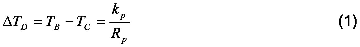
In mathematical terms, the difference ATD in the phase-transition temperatures between the solid phase and the liquid phase in the bulk medium 216 and in the confined medium 222 may be expressed with the Gibbs- Thompson equation
Figure imgf000011_0001
where TB and Tc are the phase-transition temperatures of the bulk medium 216 and confined medium 222, respectively, kp is a constant characterizing the medium, and i^ is a pore radius of a pore 214A, 214B.
It should be noted that the strict limits between the solid state and the liquid state are introduced for the ease of illustration. In real porous sys¬ tems, the pore characteristics may vary between the pores 214A, 214B, and the first phase-transition temperature 312 Ti and the second phase-transition temperature 314 T2 should be understood as average temperatures or other temperature measures that characterize the temperature behaviour of the me¬ dium in a plurality of pores 214A, 214B.
With reference to Figures 4A, 4B, and 4C, let us consider the phase transitions shown in Figure 3 on a pore level. Figure 5 shows an example of NMR spectra 506 to 512 of the sam¬ ple during sample temperature evolution from the first phase-transition tem¬ perature 312 Ti to the second phase-transition temperature 314 T2 shown in Figure 3. The horizontal axis 500 shows a chemical shift in arbitrary units, such as ppm (parts per million), while the vertical axis 502 shows the spectrum in- tensity in arbitrary units, such as power units. The reference point 504 corre¬ sponding to a zero chemical shift is labelled with a vertical bar and the value of the chemical shift increases to the left from the reference point 504.
The NMR spectra 506 to 512 may be obtained by applying the elec¬ tromagnetic stimulation including radio frequencies corresponding to the chemical shifts expected to appear in the spectra 506 to 512. In an embodi¬ ment, an appropriate frequency content of the electromagnetic stimulation is achieved by subjecting the sample unit 106 to a short electromagnetic pulse generated by the stimulation means 108, 118. In this case, the required spec¬ trum range is measured at once. The quality of the spectrum 506 to 512 may be improved by repeating the pulse and by co-adding the spectrum compo¬ nents.
The response signal 122 is detected by the detecting means 110, 116 and the digital response signal 124 is taken to the recording unit 112. The recording unit 112 may store the spectrum components and co-add the spec¬ trum components in order to generate a sum spectrum 506 to 512.
Figure 4A illustrates the bulk medium 404 surrounding a particle 408 of the porous substance and the confined medium 402 confined in a pore 400 of the particle 408 during the first time period 306. At this stage, the bulk me- dium 404 and the confined medium 402 are in the liquid state, and the probe gas dissolved in the medium may freely access the pore 400 by normal physi¬ cal mechanisms, such as those driven by thermal effects. The probe gas dis¬ solved in the medium is represented by black dots.
The first NMR spectrum 506 in Figure 5 represents an example of an NMR spectrum recorded during the first time period 306. The first NMR spectrum 506 may include a first signal (C) 514 and a second signal (B) 516 originating from probe gas dissolved in the liquid-state medium. The first signal 514 originates from the probe gas dissolved in the confined medium 402 that is in the liquid state. The second signal 516 originates from the probe gas dis- solved in the bulk medium 404 that is in the liquid state.
The first signal 514 and the second signal 516 provide pore charac¬ teristics, such as an average pore size and a pore size distribution. The aver¬ age pore size may be obtained from the center-of-mass of the first signal 514 while the pore size distribution may be obtained from the shape of the first sig- nal 514. Furthermore, the first signal 514 provides a pore volume characteriz¬ ing the integrated volume of the pores 214A, 214B in the sample. The pore volume may be obtained by taking an integral over the first signal 514.
In an embodiment of the invention, the pore radius Rp of a pore is obtained from formula
Figure imgf000012_0001
where δc and δB are the chemical shifts of the first signal 514 and second signal 516, respectively. Parameters a, b, c, and d are fitting parameters ob¬ tained for reference samples.
Figure 4B illustrates the bulk medium 404 and the confined medium 402 during the second time interval 308. At this stage, the bulk medium 404 primarily is in the solid state providing a shield around the particle 408 and re¬ ducing the medium and the probe gas either entering or exiting the pore 400. The confined medium 402 primarily is in the liquid state.
A second and third NMR spectra 508 and 510 represent an example of NMR spectra recorded during the second time interval 308. The second NMR spectrum 508 is recorded at a higher temperature than the temperature applied to the third NMR spectrum 510.
In the second NMR spectrum, the second signal 516 has weakened as the phase transition from the liquid state to the solid state in the bulk me- dium 404 has started. The first signal 514 can still be identified as the confined medium 402 is primarily in the liquid state. However, at this stage, the solidifi¬ cation in the confined medium 402 confined to the largest pores has started, thus giving rise to an appearance of a third signal (D) 520.
In the third NMR spectrum 510, the second signal 516 does not oc- cur due to the solidification of the bulk medium 404. The first signal 514 has weakened and the third signal 520 has gained strength.
Figure 4C illustrates the bulk medium 404 and the confined medium 402 during the third time interval 310. The bulk medium 404 is in the solid state, thus reducing the exchange of the medium and the probe gas between the pore 400 and the surroundings of the particle 408. At this stage, the con¬ fined medium 402 is in the solid state, and due to the larger density in the solid state than in the liquid state, gas pockets 406 have been created as a result of shrinkage of the confined medium 402. For this reason, different magnetic en¬ vironments have been created between the probe gas confined in the pore 400 and the probe gas dissolved in the bulk medium 404.
The fourth NMR spectrum 512 represents an example of an NMR spectrum recorded during the third time interval 310. At this stage, the first sig¬ nal 514 is relatively weak and indicates a residual of a liquid-phase confined medium 402 in some of the pores 400. The third signal 520 has further gained strength due to the increased volume of the gas pockets 406.
In an embodiment of the invention, the probe gas and the medium are selected to have a higher solubility of the probe gas to the medium in the liquid state than the solubility of the probe gas to the medium in the solid state. The higher solubility in the liquid state increases the quantity of the probe gas being introduced in the gas pockets 406 when the confined medium 402 trans¬ forms from the liquid state to the solid state. The increase in the quantity of the probe gas in the gas pockets improves the sensitivity of the NMR measure¬ ment to the phase transition, thus improving the accuracy of the determination of the pore characteristic.
The perturbation due to the interaction of a probe gas atom with its surroundings in the gas pockets 406 lowers the magnetic shielding σ of the probe nuclei. The smaller the gas pocket 406, the stronger the perturbation, and the higher the chemical shift of the third signal 520. As the size of the pocket 406 is proportional to the size of the pore 402, the chemical shift of the third signal 520 decreases with increasing pore size. In an embodiment of the invention, the relation between the pore radius Rp and chemical shift δ of the third signal 520 is expressed as
Figure imgf000014_0001
where a, b, c and d are least-squares parameters that can be determined from reference samples. Figure 6 illustrates graphically Eq. (3). The horizontal axis 600 shows the chemical shift while the vertical axis 602 shows the pore radius. The least squares parameters a, b, c, and d and Eq. (3) define a reference curve 606 that may be obtained by determining the chemical shift 608 of the third signal 520 for a porous substance with known pore size characteristics. In this case, calibration points 604A, 604B, 604C have been determined and a least- squares fit has been carried out by using Eq. (3). The pore radius Rs of a sam¬ ple with unknown pore characteristics may be obtained by determining the chemical shift δs of the third signal 520 and by using Eq. (3).
Figures 3, 4A, 4B, 4C, and 5 illustrate an example of a sample his- tory. The sample is typically prepared within the temperature limits defined by the first time period 306 since both the bulk medium 404 and the confined me¬ dium 402 are in the liquid state. The direction of the time evolution is not, how¬ ever, critical to the present solution, as long as the sample unit 106, 200 has experienced the first time period 306, i.e. a stage when both the bulk medium 404 and the confined medium 402 occur in the liquid state in order to enable the probe gas to access the pores 400. The actual measurement temperature at which the determination of the pore characteristics is carried out may be selected relatively freely. However, the measurement temperature may be fixed at a value depending on factors, such as the temperature of the reference measurement, characteristics of the medium, and pore characteristics to be determined.
In an embodiment of the invention, a plurality of NMR measure¬ ments are carried out at sample temperatures between the first sample tem- perature and the second sample temperature, thus producing a trend of re¬ sponse signals as a function of the sample temperature. The first sample tem¬ perature and the second sample temperature correspond to the first transition temperature 312 and the second transition temperature 314, respectively. The NMR measurements result in NMR spectra similar to NMR spectra 506 to 512. The trend of the response signals may be monitored by determining the strength of the NMR signals 514, 516, 520.
In an embodiment of the invention, the trend of the third signal 520 is recorded and the solidification temperature of the confined medium 402 is determined from the trend. In the solidification temperature, the third signal 520 vanishes. The pore radius Rp may then be obtained from Eq. (1 ) where the solidification temperature of the bulk medium 404 may be taken from literature or from the trend of the second signal 516.
In an embodiment of the invention, the sample temperature is in¬ creased between successive measurements in order to avoid supercooling effects of the sample. After each measurement, the sample may be allowed to stabilize.
The sample temperature may be monitored by measuring directly the sample temperature in the sample unit 106, 200. In an embodiment, the sample unit 106, 200 includes a capillary tube including an NMR active chemi- cal giving an NMR signal which is sensitive to temperature. The actual tem¬ perature may be determined from the chemical shift of the signal generated from the chemical and from a calibration curve.
With reference to Figure 7, embodiments of the method of preparing a sample for the determination of a pore characteristic of a porous substance with nuclear magnetic resonance spectroscopy are presented. In 700, the method starts.
In 702, the porous substance is placed into an air-tight container 202.
In 704, a liquid-phase medium is inserted into the air-tight container 202, thus producing a confined portion 222 and a bulk portion 216 of the me¬ dium, the confined portion 222 being confined into the pores 214A, 214B of the porous substance and the bulk portion 216 surrounding at least a portion of the porous substance, the medium being selected to generate a magnetic envi¬ ronment for probe gas confined to the pores 214A, 214B that differs from the magnetic environment of the probe gas dissolved in the bulk portion 216. In 706, a quantity of probe gas is dissolved into the medium, the probe gas being inert to the medium and to the porous substance and having a nuclear magnetic response to electromagnetic stimulation, the nuclear mag¬ netic response depending on the magnetic environment of the probe gas, thus transferring at least a portion of the probe gas into the pores as dissolved in the confined portion 222.
In 708, the air-tight container 202 is sealed. In 710, the method ends.
With reference to Figure 8, embodiments of a method of determin¬ ing a pore characteristic of a porous substance are presented. In 800, the method starts.
In 802, the measurement temperature is adjusted. In 804, a sample is subjected to an external magnetic field 128, the sample including the porous substance and a medium with a confined portion 222 confined into the pores of the porous substance and a bulk portion 216 surrounding at least a portion of the porous substance, the sample further in¬ cluding probe gas soluble to the medium and inert to the medium and to the porous substance and having a nuclear magnetic response to electromagnetic stimulation, the nuclear magnetic response depending on the magnetic envi¬ ronment of the probe gas, at least a portion of the probe gas being confined to the pores 214A, 214B and being transferred into the pores as dissolved in the confined portion 222, the medium being selected to generate a different mag¬ netic environment for the probe gas confined to the pores 214A, 214B from the magnetic environment of the probe gas dissolved in the bulk portion 216.
In 806, electromagnetic stimulation is applied to the sample, the electromagnetic stimulation being selected to induce at least one response signal 122 in the probe gas. In an embodiment of the invention, the electro¬ magnetic stimulation is selected to induce a first response signal 514 in the probe gas dissolved in the confined portion 402 and second response signal 516 in the probe gas dissolved in the bulk portion 404. In 808, the at least one response signal is recorded. In an embodi¬ ment of the invention, the first response signal 514 and the second response signal 516 are recorded.
In 810, a decision is made whether or not to continue the NMR measurement at a different temperature. If the NMR measurement is contin¬ ued, the measurement temperature is adjusted in 802.
If the NMR measurement is not continued, the pore characteristic is determined from the at least one response signal 122 in 812. In an embodi¬ ment of the invention, the pore characteristic is determined from the first re- sponse signal 514 and the second response signal 516.
In 814, the method ends.
Even though the invention is described above with reference to an example according to the accompanying drawings, it is clear that the invention is not restricted thereto but can be modified in several ways within the scope of the appended claims.

Claims

Claims
1. A method of determining a pore characteristic of a porous sub¬ stance, c h a r a c t e r i z e d by subjecting (804) a sample to an external magnetic field, the sample including the porous substance and a medium with a confined portion confined into the pores of the porous substance and a bulk portion surrounding at least a portion of the porous substance, the sample further including probe gas soluble to the medium and inert to the medium and to the porous substance and having a nuclear magnetic response to electromagnetic stimulation, the nuclear magnetic response depending on the magnetic environment of the probe gas, at least a portion of the probe gas being confined to the pores and being transferred into the pores as dissolved in the confined portion, the me¬ dium being selected to generate a magnetic environment for the probe gas confined to the pores that differs from the magnetic environment of the probe gas dissolved in the bulk portion; applying (806) electromagnetic stimulation to the sample, the elec¬ tromagnetic stimulation being selected to induce at least one response signal in the probe gas; recording (808) the at least one response signal; and determining (812) the pore characteristic from the at least one re¬ sponse signal.
2. The method of claim 1 , c h a r a c t e r i z e d in that the medium is selected to have a lower phase-transition temperature in the confined portion than the phase-transition temperature in the bulk portion, the phase transition taking place from the liquid phase to the solid phase, the medium being further selected to have larger density in the solid phase than the density in the liquid phase, a sample temperature history including a first sample temperature and a second sample temperature following the first sample temperature, at which first sample temperature the confined portion and the bulk portion appear in the liquid state, and at which second sample temperature the confined portion and the bulk portion appear in the solid state, the method further including sub¬ jecting (804) the sample to the external magnetic field in the second sample temperature.
3. The method of claim 2, c h a r a c t e r i z e d by subjecting (804) the sample to the external magnetic field, applying (806) electromagnetic stimulation to the sample, and recording (808) the at least one response signal in a plurality of sample temperatures between the first sample temperature and the second sample temperature, thus producing a trend of response signals as a function of the sample temperature; and determining (812) the pore characteristic from the trend of the re- sponse signals as a function of the sample temperature.
4. The method of claim 2, characterized in that the probe gas and the medium are selected to have higher solubility of the probe gas to the medium in the liquid state than the solubility of the probe gas to the me¬ dium in the solid state.
5. The method of claim 2, characterized by determining
(812) at least one pore characteristic from the response signal, the pore char¬ acteristic being selected from a list comprising: pore size distribution, pore vol¬ ume of the porous substance.
6. The method of claim 1, characterized in that the medium is condensed fluid, the medium being selected to provide a magnetic environ¬ ment for the probe gas dissolved in the confined portion that differs from the magnetic environment for the probe gas dissolved in the bulk portion, and the method further including: applying (806) electromagnetic stimulation to the sample, the elec- tromagnetic stimulation being selected to induce a first response signal in the probe gas dissolved in the confined portion and second response signal in the probe gas dissolved in the bulk portion; recording (808) the first response signal and the second response signal; and determining (812) the pore characteristic from the first response signal and the second response signal.
7. The method of claim 6, characterized in that the medium is a liquid crystal and selected to have an isotropic phase in the confined por¬ tion and an anisotropic phase in the bulk portion in a measurement tempera- ture.
8. The method of claim 6, characterized by determining (812) at least one pore characteristic from the first response signal and the second response signal, the pore characteristic being selected from a list com¬ prising: pore size distribution, pore volume.
9. The method of claim 1, characterized in that the probe gas is xenon.
10. The method of claim 1, characterized in that the medium is selected from a group comprising: acetonitrile, naphthalene.
11. A preparation method of preparing a sample for the determina¬ tion of a pore characteristic of a porous substance with nuclear magnetic reso- nance spectroscopy, characterized by placing (702) the porous substance into an air-tight container; inserting (704) a liquid-phase medium into the air-tight container, thus producing a confined portion and a bulk portion of the medium, the con¬ fined portion being confined into the pores of the porous substance and the bulk portion surrounding at least a portion of the porous substance, the me¬ dium being selected to generate a magnetic environment for probe gas con¬ fined to the pores that differs from the magnetic environment of the probe gas dissolved in the bulk portion; and dissolving (706) a quantity of probe gas into the medium, the probe gas being inert to the medium and to the porous substance and having a nu¬ clear magnetic response to electromagnetic stimulation, the nuclear magnetic response depending on the magnetic environment of the probe gas, thus transferring at least a portion of the probe gas into the pores as dissolved in the confined portion.
12. The method of claim 11, characterized by inserting (704) the liquid-phase medium into the air-tight container, the medium being selected to have a lower phase-transition temperature in the confined portion than the phase-transition temperature in the bulk portion, the phase transition taking place from the liquid phase to the solid phase, the medium being further se- lected to have a larger density in the solid phase than the density in the liquid phase.
13. The method of claim 12, characterized in that the probe gas and the medium are selected to have a higher solubility of the probe gas to the medium in the liquid state than the solubility of the probe gas to the me- dium in the solid state.
14. The method of claim 11, characterized in that the me¬ dium is condensed fluid, the medium being selected to provide a magnetic en¬ vironment for the probe gas dissolved in the confined portion that differs from the magnetic environment for the probe gas dissolved in the bulk portion, which thus results in that a response signal is generated in the probe gas dis¬ solved in the confined portion that differs from a response signal being gener- ated in the bulk portion when electromagnetic stimulation is applied to the sample.
15. The method of claim 14, characterized in that the me¬ dium is a liquid crystal and selected to have an isotropic phase in the confined portion and an anisotropic phase in the bulk portion in a measurement tem¬ perature.
16. A sample unit for determining a pore characteristic of a porous substance with nuclear magnetic resonance spectroscopy, including a porous substance, characterized in that the sample unit further includes: a medium including a confined portion confined into the pores
(214A, 214B) of the porous substance and a bulk portion surrounding at least a portion of the porous substance; probe gas soluble to the medium and inert to the medium and to the porous substance and having a nuclear magnetic response to electromagnetic stimulation, the nuclear magnetic response depending on the magnetic envi¬ ronment of the probe gas, at least a portion of the probe gas being confined to the pores and being transferred into the pores as dissolved in the confined por¬ tion; and the medium being selected to generate a magnetic environment for the probe gas confined to the pores that differs from the magnetic environment of the probe gas dissolved in the bulk portion.
17. The sample unit of claim 16, characterized in that the medium is selected to have a lower phase-transition temperature in the con¬ fined portion than the phase-transition temperature in the bulk portion, the phase transition taking place from the liquid phase to the solid phase, the me¬ dium being further selected to have larger density in the solid phase than the density in the liquid phase.
18. The sample unit of claim 17, characterized in that the sample unit has a sample temperature history including a first sample tempera- ture and a second sample temperature following the first sample temperature, at which first sample temperature the confined portion and the bulk portion ap¬ pear in the liquid state, and at which second sample temperature the confined portion and the bulk portion appear in the solid state; and the sample temperature is the second sample temperature when determining the pore characteristic.
19. The sample unit of claim 17, characterized in that the probe gas and the medium are selected to have a higher solubility of the probe gas to the medium in the liquid state than the solubility of the probe gas to the medium in the solid state.
20. The sample unit of claim 16, characterized in that the medium is condensed fluid, the medium being selected to provide a magnetic environment for the probe gas dissolved in the confined portion that differs from the magnetic environment for the probe gas dissolved in the bulk portion, which thus results in that a different response signal is generated in the probe gas dissolved in the confined portion that differs from a response signal being generated in the bulk portion when electromagnetic stimulation is applied to the sample unit.
21. The sample unit of claim 20, characterized in that the medium is a liquid crystal and selected to have an isotropic phase in the con- fined portion and an anisotropic phase in the bulk portion in a measurement temperature.
PCT/FI2005/050353 2004-10-12 2005-10-11 Method of determining pore characteristic, preparation method of sample unit, and sample unit Ceased WO2006040407A1 (en)

Priority Applications (1)

Application Number Priority Date Filing Date Title
US11/665,132 US20070287184A1 (en) 2004-10-12 2005-10-11 Method Of Determining Pore Characteristic, Preparation Method Of Sample Unit, And Sample Unit

Applications Claiming Priority (2)

Application Number Priority Date Filing Date Title
FI20045381 2004-10-12
FI20045381A FI20045381A0 (en) 2004-10-12 2004-10-12 Process for determining porosity property, method for producing a test unit and a test unit

Publications (1)

Publication Number Publication Date
WO2006040407A1 true WO2006040407A1 (en) 2006-04-20

Family

ID=33306101

Family Applications (1)

Application Number Title Priority Date Filing Date
PCT/FI2005/050353 Ceased WO2006040407A1 (en) 2004-10-12 2005-10-11 Method of determining pore characteristic, preparation method of sample unit, and sample unit

Country Status (3)

Country Link
US (1) US20070287184A1 (en)
FI (1) FI20045381A0 (en)
WO (1) WO2006040407A1 (en)

Families Citing this family (6)

* Cited by examiner, † Cited by third party
Publication number Priority date Publication date Assignee Title
GB201222287D0 (en) 2012-12-11 2013-01-23 Ct For Process Innovation Ltd Methods for making active crystalline materials
RU2539775C1 (en) * 2013-12-26 2015-01-27 Федеральное государственное бюджетное образовательное учреждение высшего профессионального образования "Калининградский государственный технический университет" Method of measuring dimensions of microcrystals
WO2018106828A1 (en) * 2016-12-07 2018-06-14 New York University System and method for magnetic resonance mapping of physical and chemical changes in conducting structures
US11921067B2 (en) * 2015-04-17 2024-03-05 New York University System and method for magnetic resonance mapping of physical and chemical changes in conducting structures
US10712297B2 (en) 2015-04-17 2020-07-14 New York University Systems and methods for super-resolution surface-layer microscopy using magnetic resonance
JP6757946B2 (en) * 2016-12-12 2020-09-23 国立研究開発法人理化学研究所 NMR measurement method and equipment

Citations (4)

* Cited by examiner, † Cited by third party
Publication number Priority date Publication date Assignee Title
US3213355A (en) * 1962-04-06 1965-10-19 Socony Mobil Oil Co Inc Nmr measurement of container dimensions
US6084408A (en) * 1998-02-13 2000-07-04 Western Atlas International, Inc. Methods for acquisition and processing of nuclear magnetic resonance signals for determining fluid properties in petroleum reservoirs having more than one fluid phase
US6369567B1 (en) * 1999-03-19 2002-04-09 Schlumberger Technology Corporation Nuclear magnetic resonance method and apparatus for determining pore characteristics of rocks and other porous materials
US20030017110A1 (en) * 1996-03-29 2003-01-23 The Regents Of The University Of California Enhancement of NMR and MRI in the presence of hyperpolarized noble gases

Family Cites Families (2)

* Cited by examiner, † Cited by third party
Publication number Priority date Publication date Assignee Title
US5545396A (en) * 1994-04-08 1996-08-13 The Research Foundation Of State University Of New York Magnetic resonance imaging using hyperpolarized noble gases
US7126332B2 (en) * 2001-07-20 2006-10-24 Baker Hughes Incorporated Downhole high resolution NMR spectroscopy with polarization enhancement

Patent Citations (4)

* Cited by examiner, † Cited by third party
Publication number Priority date Publication date Assignee Title
US3213355A (en) * 1962-04-06 1965-10-19 Socony Mobil Oil Co Inc Nmr measurement of container dimensions
US20030017110A1 (en) * 1996-03-29 2003-01-23 The Regents Of The University Of California Enhancement of NMR and MRI in the presence of hyperpolarized noble gases
US6084408A (en) * 1998-02-13 2000-07-04 Western Atlas International, Inc. Methods for acquisition and processing of nuclear magnetic resonance signals for determining fluid properties in petroleum reservoirs having more than one fluid phase
US6369567B1 (en) * 1999-03-19 2002-04-09 Schlumberger Technology Corporation Nuclear magnetic resonance method and apparatus for determining pore characteristics of rocks and other porous materials

Non-Patent Citations (3)

* Cited by examiner, † Cited by third party
Title
STRANGE J.H. ET AL: "Pore Characteristics by NMR", IEE COLLOQUIUM ON "NMR/MRI USED IN NDT", no. 1994/033, 1994, pages 5/1 - 5/3 *
TELKKI ET AL: "The freezing and melting phenoma in mesoporous materials as studied by 129 Xe NMR", MAGNETIC RESONANCE IMAGING, PROCEEDINGS OF THE 7TH INTERNATIONAL CONFERENCE ON RECENT ADVANCES IN MR APPLICATIONS TO POROUS MEDIA 07-08 JULY 2004, February 2005 (2005-02-01), pages 407 - 444 *
TELKKI V. ET AL: "Behavior of Acetonitrile Confined to Mesoporous Silica Gels as Stidied by 129 XE NMR: A Novel Method for Determining the Pore Sizes, Published on web 12.12.2004", J.PHYS.CHEM., vol. 109, 2005 *

Also Published As

Publication number Publication date
US20070287184A1 (en) 2007-12-13
FI20045381A0 (en) 2004-10-12

Similar Documents

Publication Publication Date Title
Strange et al. Characterization of porous solids by NMR
Bielecki et al. Temperature dependence of207Pb MAS spectra of solid lead nitrate. an accurate, sensitive thermometer for variable-temperature MAS
EP1999493B1 (en) Compact and portable low-field pulsed nmr dispersion analyzer
Loening et al. Measurement of convection and temperature profiles in liquid samples
JPH07501625A (en) Method and device for measuring AC magnetic susceptibility and DC magnetization of a sample
GB2489005A (en) Examination of porosity by NMR and intrusion porosimetry
US11719655B2 (en) Method for measuring oil-water distribution using dynamic nuclear polarization for magnetic resonance imaging (DNP-MRI)
Allen et al. Internal surfaces of porous media studied by nuclear magnetic resonance cryoporometry
Corruccini et al. Pulsed NMR experiments in superfluid He 3
Rhodes et al. NMR of platinum catalysts. II. Relaxation
Ahonen et al. Phase Diagram of Liquid He 3 between 0.7 and 2.5 mK
WO2006040407A1 (en) Method of determining pore characteristic, preparation method of sample unit, and sample unit
US10371653B2 (en) Multi-phase metering device for oilfield applications
Stroud et al. Magnetic particle based MRI thermometry at 0.2 T and 3 T
Meredith et al. Application of a SQUID magnetometer to NMR at low temperatures
Nicasy et al. Ultra Fast Imaging NMR method for measuring fast transport processes in thin porous media
Strange et al. Pore size distribution mapping
Khokhlov et al. Characterization of pore size distribution in porous silicon by NMR cryoporosimetry and adsorption methods.
Pigliapochi et al. Ultrafast inside‐out NMR assessment of rechargeable cells
Barker et al. Spin dynamics of 3He in aerogel
Comment et al. Magnetic properties of pure and Gd-doped EuO probed by NMR
Mito et al. Magnetic properties of the pressure-induced ordering state in Yb In Cu 4 investigated with NMR, magnetization, and x-ray diffraction measurements
Strange et al. Characterising porous media
Ahonen et al. Transverse NMR measurements on superfluid He 3
Aton et al. Spin-density magnetization near magnetic atoms in copper: Cu Mn

Legal Events

Date Code Title Description
AK Designated states

Kind code of ref document: A1

Designated state(s): AE AG AL AM AT AU AZ BA BB BG BR BW BY BZ CA CH CN CO CR CU CZ DE DK DM DZ EC EE EG ES FI GB GD GE GH GM HR HU ID IL IN IS JP KE KG KM KP KR KZ LC LK LR LS LT LU LV LY MA MD MG MK MN MW MX MZ NA NG NI NO NZ OM PG PH PL PT RO RU SC SD SE SG SK SL SM SY TJ TM TN TR TT TZ UA UG US UZ VC VN YU ZA ZM ZW

AL Designated countries for regional patents

Kind code of ref document: A1

Designated state(s): GM KE LS MW MZ NA SD SL SZ TZ UG ZM ZW AM AZ BY KG KZ MD RU TJ TM AT BE BG CH CY CZ DE DK EE ES FI FR GB GR HU IE IS IT LT LU LV MC NL PL PT RO SE SI SK TR BF BJ CF CG CI CM GA GN GQ GW ML MR NE SN TD TG

121 Ep: the epo has been informed by wipo that ep was designated in this application
NENP Non-entry into the national phase

Ref country code: DE

WWE Wipo information: entry into national phase

Ref document number: 11665132

Country of ref document: US

122 Ep: pct application non-entry in european phase

Ref document number: 05795270

Country of ref document: EP

Kind code of ref document: A1

WWP Wipo information: published in national office

Ref document number: 11665132

Country of ref document: US