WO2006019928A2 - Concentric internal combustion rotary engine - Google Patents
Concentric internal combustion rotary engine Download PDFInfo
- Publication number
- WO2006019928A2 WO2006019928A2 PCT/US2005/025019 US2005025019W WO2006019928A2 WO 2006019928 A2 WO2006019928 A2 WO 2006019928A2 US 2005025019 W US2005025019 W US 2005025019W WO 2006019928 A2 WO2006019928 A2 WO 2006019928A2
- Authority
- WO
- WIPO (PCT)
- Prior art keywords
- rotor
- rotary engine
- internal combustion
- pockets
- elliptical body
- Prior art date
Links
Classifications
-
- F—MECHANICAL ENGINEERING; LIGHTING; HEATING; WEAPONS; BLASTING
- F01—MACHINES OR ENGINES IN GENERAL; ENGINE PLANTS IN GENERAL; STEAM ENGINES
- F01C—ROTARY-PISTON OR OSCILLATING-PISTON MACHINES OR ENGINES
- F01C1/00—Rotary-piston machines or engines
- F01C1/30—Rotary-piston machines or engines having the characteristics covered by two or more groups F01C1/02, F01C1/08, F01C1/22, F01C1/24 or having the characteristics covered by one of these groups together with some other type of movement between co-operating members
- F01C1/36—Rotary-piston machines or engines having the characteristics covered by two or more groups F01C1/02, F01C1/08, F01C1/22, F01C1/24 or having the characteristics covered by one of these groups together with some other type of movement between co-operating members having both the movements defined in sub-groups F01C1/22 and F01C1/24
-
- F—MECHANICAL ENGINEERING; LIGHTING; HEATING; WEAPONS; BLASTING
- F02—COMBUSTION ENGINES; HOT-GAS OR COMBUSTION-PRODUCT ENGINE PLANTS
- F02B—INTERNAL-COMBUSTION PISTON ENGINES; COMBUSTION ENGINES IN GENERAL
- F02B53/00—Internal-combustion aspects of rotary-piston or oscillating-piston engines
-
- F—MECHANICAL ENGINEERING; LIGHTING; HEATING; WEAPONS; BLASTING
- F01—MACHINES OR ENGINES IN GENERAL; ENGINE PLANTS IN GENERAL; STEAM ENGINES
- F01C—ROTARY-PISTON OR OSCILLATING-PISTON MACHINES OR ENGINES
- F01C11/00—Combinations of two or more machines or engines, each being of rotary-piston or oscillating-piston type
- F01C11/006—Combinations of two or more machines or engines, each being of rotary-piston or oscillating-piston type of dissimilar working principle
- F01C11/008—Combinations of two or more machines or engines, each being of rotary-piston or oscillating-piston type of dissimilar working principle and of complementary function, e.g. internal combustion engine with supercharger
-
- F—MECHANICAL ENGINEERING; LIGHTING; HEATING; WEAPONS; BLASTING
- F02—COMBUSTION ENGINES; HOT-GAS OR COMBUSTION-PRODUCT ENGINE PLANTS
- F02B—INTERNAL-COMBUSTION PISTON ENGINES; COMBUSTION ENGINES IN GENERAL
- F02B53/00—Internal-combustion aspects of rotary-piston or oscillating-piston engines
- F02B53/04—Charge admission or combustion-gas discharge
-
- F—MECHANICAL ENGINEERING; LIGHTING; HEATING; WEAPONS; BLASTING
- F03—MACHINES OR ENGINES FOR LIQUIDS; WIND, SPRING, OR WEIGHT MOTORS; PRODUCING MECHANICAL POWER OR A REACTIVE PROPULSIVE THRUST, NOT OTHERWISE PROVIDED FOR
- F03C—POSITIVE-DISPLACEMENT ENGINES DRIVEN BY LIQUIDS
- F03C2/00—Rotary-piston engines
- F03C2/30—Rotary-piston engines having the characteristics covered by two or more of groups F03C2/02, F03C2/08, F03C2/22, F03C2/24 or having the characteristics covered by one of these groups together with some other type of movement between co-operating members
- F03C2/306—Rotary-piston engines having the characteristics covered by two or more of groups F03C2/02, F03C2/08, F03C2/22, F03C2/24 or having the characteristics covered by one of these groups together with some other type of movement between co-operating members having both the movements defined in sub-groups F03C2/22 and F03C2/24
-
- F—MECHANICAL ENGINEERING; LIGHTING; HEATING; WEAPONS; BLASTING
- F04—POSITIVE - DISPLACEMENT MACHINES FOR LIQUIDS; PUMPS FOR LIQUIDS OR ELASTIC FLUIDS
- F04C—ROTARY-PISTON, OR OSCILLATING-PISTON, POSITIVE-DISPLACEMENT MACHINES FOR LIQUIDS; ROTARY-PISTON, OR OSCILLATING-PISTON, POSITIVE-DISPLACEMENT PUMPS
- F04C18/00—Rotary-piston pumps specially adapted for elastic fluids
-
- F—MECHANICAL ENGINEERING; LIGHTING; HEATING; WEAPONS; BLASTING
- F04—POSITIVE - DISPLACEMENT MACHINES FOR LIQUIDS; PUMPS FOR LIQUIDS OR ELASTIC FLUIDS
- F04C—ROTARY-PISTON, OR OSCILLATING-PISTON, POSITIVE-DISPLACEMENT MACHINES FOR LIQUIDS; ROTARY-PISTON, OR OSCILLATING-PISTON, POSITIVE-DISPLACEMENT PUMPS
- F04C2250/00—Geometry
- F04C2250/30—Geometry of the stator
- F04C2250/301—Geometry of the stator compression chamber profile defined by a mathematical expression or by parameters
-
- Y—GENERAL TAGGING OF NEW TECHNOLOGICAL DEVELOPMENTS; GENERAL TAGGING OF CROSS-SECTIONAL TECHNOLOGIES SPANNING OVER SEVERAL SECTIONS OF THE IPC; TECHNICAL SUBJECTS COVERED BY FORMER USPC CROSS-REFERENCE ART COLLECTIONS [XRACs] AND DIGESTS
- Y02—TECHNOLOGIES OR APPLICATIONS FOR MITIGATION OR ADAPTATION AGAINST CLIMATE CHANGE
- Y02T—CLIMATE CHANGE MITIGATION TECHNOLOGIES RELATED TO TRANSPORTATION
- Y02T10/00—Road transport of goods or passengers
- Y02T10/10—Internal combustion engine [ICE] based vehicles
- Y02T10/12—Improving ICE efficiencies
Definitions
- the field of the invention generally relates to combustion engines. More specifically, the field of the invention relates to internal combustion rotary engines.
- the internal combustion rotary engine is one alternative to piston-based combustion engines which can mitigate, to some extent, these inherent inefficiencies.
- Felix Wankel is credited with inventing an internal combustion rotary engine which operates by using a triangular-shaped rotor spinning within a housing shaped in the manner of a epitrochoid (e.g., peanut-shaped) .
- the internal combustion rotary engine includes a number of advantages over piston-based combustion engines. [0006] First, internal combustion rotary engines are more lightweight and compact. Second, internal combustion rotary engines are smoother since there is no reciprocating motion of pistons.
- internal combustion rotary engines have an extended power stroke rotation of the output shaft as compared to their piston-based counterparts. Fourth, there are fewer moving parts, e.g., no valves, connecting rods, cams, and timing chains. Timing of the intake and exhaust strokes are accomplished directly by the motion of the rotor. Fifth, internal combustion rotary engines have a generally flat torque curve because no valves are used. Sixth, combustion in internal combustion rotary engines are generally cooler than their piston-based counterparts. This means fewer oxides of nitrogen are created. Finally, internal combustion rotary engines separate the combustion region from the intake region, thereby making these engines good candidates for hydrogen fuel-based engines.
- Wankel-type internal combustion rotary engines have leak combustion gases, making these types of engines less desirable.
- the rotational speed (i.e., revolutions per minute (RPM)) of Wankel-type internal combustion rotary engines is limited because of the manner in which the triangular rotor flip-flops around the interior of the epitrochoid housing.
- RPM revolutions per minute
- An internal combustion rotary engine includes a housing having an inlet and an outlet and a rotatable rotor centrally mounted within the housing.
- the rotor includes a plurality of pockets located about its circumference.
- the rotor is further connected to a rotor shaft that is mechanically connected to an output shaft.
- a rotatable elliptical body is disposed in each of the plurality of pockets.
- Each rotatable elliptical body is coupled to respective planet gears.
- Each of the respective planet gears is meshed with a centrally disposed fixed sun gear.
- an ignition source is disposed in each of the plurality of pockets.
- each elliptical body rotates through 720°.
- the rotary engine includes four separate regions in which the intake, compression, power, and exhaust strokes take place.
- the rotor includes three pockets located about its circumference. The pockets may be equally spaced about the circumference of the rotor.
- an internal combustion rotary engine includes a housing having an inlet and an outlet, the inlet being coupled to a compressor.
- a rotatable rotor is centrally mounted within the housing.
- the rotor includes a plurality of pockets located about its circumference.
- the rotor is connected to a rotor shaft, which in turn, is coupled to an output shaft.
- each elliptical body is disposed in each of the plurality of pockets with each elliptical body being mounted on a rotational shaft at one end and coupled at an opposing end to a planetary gear. Each planet gear is engages with a fixed, centrally located fixed sun gear. An ignition source is disposed in each of the plurality of pockets. For each full rotation of the rotor (i.e., 360°) each elliptical body rotates through 720°.
- each elliptical body includes a seal disposed on an exterior surface thereof.
- the elliptical body is interposed between two outer spools to form an elliptical body assembly.
- the rotor is coupled to a distributor.
- the distributor rotates with the rotor and includes an electrical contact for each ignition source (e.g., three electrical contacts) .
- the rotor shaft includes a passageway or bore therein in fluid communication with a bore in the rotational shaft of the elliptical body assembly.
- the passageway and bore provide an access path for oil or other lubricant to lubricate the elliptical body bearings, and the planetary and sun gears.
- each planet gear has a pitch diameter that is equal to the pitch diameter of the sun gear.
- FIG. 1 illustrates a rotor contained within a housing of an internal combustion rotary engine according to one preferred embodiment of the invention.
- the engine housing is open to expose the rotor, the three pockets, and the three elliptical bodies.
- Fig. 2 illustrates an internal combustion rotary engine with the rotor being exposed.
- Fig. 3A illustrates a top down view of the ellipse body assembly. The rotational shaft of the ellipse body assembly is shown coupled to a planetary gear.
- Fig. 3B illustrates an end view of a ellipse body assembly taken along the line A-A in Fig. 3A.
- the assembly includes a circular end or spool containing a seal around a circumferential surface thereof.
- An elliptical body is supported on a rotational shaft.
- the coupled planetary gear is also shown.
- Fig. 4 illustrates the centralized sun gear and surrounding planetary gears. The rotational direction of the planetary gears is shown by arrows A and B. A single ellipse body assembly is also illustrated.
- Fig. 5 illustrates a rotor showing the sparkplugs connected to a central distributor.
- Fig. 6 illustrates a gearbox and reduction gears illustrating the mechanically coupled rotor shaft, jackshaft, and output shaft.
- Fig. 7 illustrates a sectional view of the engine according to one preferred aspect of the invention.
- Fig. 7 illustrates a compressor interposed between the center plate and the gear box.
- Fig. 8 illustrates a front view of the centrifugal compressor impeller taken along the line A-A in Fig. 7.
- Fig. 9 illustrates an end view of the engine illustrating the enclosed rotor.
- Fig. 1OA illustrates a magnified sectional view of an elliptical body assembly contained in a pocket formed between the rotor and housing.
- Fig. 1OB illustrates an end view of an elliptical body according to one aspect of the invention.
- Figs. 1 and 2 illustrates an internal combustion rotary engine 2 according to a preferred embodiment of the invention.
- the internal combustion rotary engine 2 includes a housing 4 which is generally oblong-shaped having a minor axis (the distance between the top and bottom portions of the housing 4 in the direction of arrow A shown in Fig. 1) and major axis (the distance between the left and right portions of the housing 4 in the direction of arrow B shown in Fig. 1) .
- the housing 4 includes an inlet 6 which serves as the inlet for the fuel/air mixture which is combusted inside the engine 2.
- the inlet 6 may be coupled to an optional compressor 8, for example, as illustrated in Figs. 7 and 8.
- the housing 4 further includes an outlet 10 which serves to exhaust combustion gases/air outside of the engine 2.
- the housing 4 when viewed in cross-section, has a profile of a spline curve.
- a rotatable rotor 12 is disposed centrally inside the housing 4.
- the rotor 12 is mounted on a rotor shaft 14 and is rotatable within the housing 4 in the direction of arrow C in Fig. 1.
- the rotor shaft 14 is mechanically connected through appropriate gearing, for example, through a jackshaft 16, to an output shaft 18 (shown e.g., in Figs. 6 and 7) .
- the rotatable rotor 12 further includes a plurality of pockets 20 located about the rotor's circumference.
- the pockets 20 generally comprise a hemispherical or semi-hemispherical cavity within the rotor 12.
- the rotor 12 includes two pockets 20.
- the pockets 20 there are three pockets 20 as is shown in Figs. 1 and 2.
- the three pockets 20 are spaced equidistant from one another (e.g., 120° spacing) .
- the pockets 20, working in connection with associated rotatable elliptical bodies 22, increase and decrease the displacement volume as the rotor 12 rotates around rotor shaft 14.
- the displacement volume is formed between an outer surface of the rotor 12 as well as the volume of the pockets 20 and the inner surface of the housing 4.
- Fig. 1 shows that an optional purge port 24 may be incorporated into the pockets 20.
- the air purge port 24 is used to aid in expelling spent combustion gases from the pocket 20. It should be understood, however, that the air purge port 24 is entirely optionally and may be omitted entirely.
- each elliptical body 22 is affixed to a rotational shaft 26.
- the rotational shaft 26 of each elliptical body 22 is connected to a planetary gear 28 (shown in dashed lines in Fig. 1 and also shown in Figs. 3A and 3B) .
- Each planetary gear 28 is meshed with a centralized, fixed sun gear 30 (shown in dashed lines in Fig. 1 and also seen in Figs. 3A and 3B) .
- the planetary gears 28 thus orbit the centralized, fixed sun gear 30 during operation of the engine 2.
- the planetary gears 28 and the centralized, fixed sun gear 30 have the same pitch diameter and have a multiple of two (2) teeth as well as a multiple of three (3) teeth (e.g., 12, 18, 24, 30, etc. teeth) .
- the elliptical bodies 22 rotate in the direction of arrow D in Fig. 1, namely, the same direction as the rotation of the rotor 12 (arrow C in Fig. 1) .
- the planetary gears 28 and sun gear 30 are geared such that the elliptical bodies 22 rotate at twice the rate (2:1) of the rotor 12.
- Fig. 1 also illustrates the outline E of an elliptical body 22 as it travels within the housing 4.
- Fig. 2 illustrates an open rotor 12 bolted through a series of bolts 32 through a center plate 34 and gear box 36 (see also Fig. 7) .
- the center plate 34 includes a plurality of engine mounting holes 38.
- Fig. 2 further illustrates three distributor mount holes 40 for securing distributor 42 (described in more detail below) .
- the elliptical bodies 22 are formed from industrial ceramic materials although other materials such as metals and alloys can also be used.
- the elliptical bodies 22 are machined or otherwise formed with strict tolerances in order to minimize any leakage of air and/or fuel between the elliptical bodies 22 and the interior of the housing 4.
- the elliptical bodies 22 are preferably sealed inside the pockets 20, for example, via seals 96.
- the elliptical body 22 is contained in an elliptical body assembly 44 that includes two circular ends 46, 48 or spools.
- each end 46, 48 may include a seal 50 for forming a combustion seal within each respective pocket 20.
- An optional wearing surface 52 for the seals 50 such as hardened steel, as is shown in Fig. 1OA, may be provided within the rotor 12.
- the seals 50 keep the fuel/air/combustion gases contained within the pocket 20 and/or housing 4.
- each elliptical body 22 also includes a rotational shaft 26 on which the elliptical body 22 is mounted.
- Fig. 4 illustrates fixed sun gear 30 and surrounding planetary gears 28.
- the fixed sun gear 30 may be affixed to the center plate 34 (shown in Fig.
- the three planetary gears 28 are equally spaced about the central sun gear 30 (separated by 120°) and are affixed, respectively, to the ends of the rotational shafts 26 of each elliptical body 22.
- the rotor shaft 14 passes through the central sun gear 30 and may be rotationally held via a rotatable bearing 58 or the like (as is shown in Fig. 7) . As seen in Figs. 4 and 7, the rotor shaft 14 continues into the gear box 36 and is mechanically coupled through a jackshaft 16 to an output shaft 18. [0036] Referring to Figs.
- an ignition source 60 is preferably associated with each pocket 20 in the rotor 12. As shown in Figs. 1 and 2, the ignition source 60 is preferably a sparkplug. In order to fire the ignition sources 60, a conventional distributor-type structure is used to fire the individual ignition sources. Fig. 5, for example, illustrates how each ignition source 60 is connected to a centralized, electrically conductive distributor 42. In this regard, no wires are directly connected to the individual sparkplugs 60. The distributor 42 is mounted directly on the rotor 12 via distributor mounting holes 40 as shown in Fig. 2. As best seen in Fig.
- distributor 42 includes three contact points 62 (such as high voltage electrical pick-ups) that are electrically connected to a respective ignition source 60 via a rigid conductor member 64 (e.g., rigid spark plug strap) .
- the distributor 42 rotates about the rotor shaft 14.
- a stationary electrical contact member 66 is provided at a point about the rotational circumference circumscribed by the contact points 62. The stationary contact member 66 is positioned such that it electrically engages with one of the three contact points 62 as the distributor 42 is rotated about its axis.
- Figs. 6 and 7 illustrate the interior of the gear box 36.
- the rotor shaft 14 includes a splined or meshed portion 14a that engages with splined or meshed portion 16a of a jack shaft 16.
- the jack shaft 16 is in turn, coupled to a splined or meshed portion 18a of an output shaft 18.
- Fig. 7 illustrates a sectional view of an engine 2 according to one preferred embodiment of the invention.
- the gear box 36 contains a series of bearings 68 or other rotational supports for holding the rotor shaft 14, jack shaft 16, and output shaft 18.
- a passageway 70 within the rotor shaft 14 may be provided to lubricate the rotational elliptical body bearings 86.
- the rotational shaft 26 of the elliptical body assembly 44 may include a bored shaft 26a that communicates with the passageway 70.
- oil passing through the passageway 70 and bored shaft 26a may act as a bearing oil return that lubes the elliptical bodies 22 and/or gears 28, 30.
- the engine 2 generally includes five regions 100, 110, 120, 130 and 140 that correspond to the four cycles of a four stroke engine.
- Region 100 which is regarded as the intake stroke, is generally bounded by space between the inlet 6 and a portion of the space formed within the lower leftmost pocket 20.
- Region 110 which is regarded at the compression stroke of the engine 2 is generally bounded by the space between the lower leftmost pocket 20 and a small portion of the top dead-center pocket 20.
- Region 120 which is bounded by the space between the elliptical body 22 and the pocket 20, is regarded as the combustion chamber.
- Region 130 which is regarded as the power stroke, is generally bounded by space between the top dead-center pocket 20 and the lower rightmost pocket 20.
- Region 140 which is regarded as the exhaust stroke, is generally bounded by the space between the lower rightmost pocket 20 and the exhaust outlet 10.
- a compressor 8 is interposed between the center plate 34 and the gear box 36.
- the compressor 8 is affixed to the rotor shaft 14 and includes an intake 8a, an output 8b, and a waste gas outlet 8c (best seen in Fig. 8) .
- Rotation of the rotor shaft 14 rotates a plurality of vanes 8d within the compressor 8 to compress air into the inlet 6 of the engine 2.
- a fuel injector 72 is disposed inline between the compressor output 8b and the engine inlet 6. The compressor 8 is able to increase the compression ratio of the engine 2.
- the engine is able to achieve a compression ratio of about 10.58.
- the compressor 8 is able to double the compression ratio of engine 2 from about 5.29 to about 10.58.
- the housing 4 of the engine 2 includes a plurality of fins 74 for cooling the engine 2.
- the fins 74 may be made of a heat conducting metal such as, for example aluminum.
- the rotor 12 includes a plurality of fan blades 76.
- the fan blades 76 may include an arcuate or toroidal shape and are used to generate airflow to cool the engine 2 during operation.
- a rotor cap 78 is affixed to the engine 2 via a plurality of bolts 79.
- the rotor cap 78 is preferably formed as a single piece and includes air redirect portions 78a to direct the airflow created by the fan blades 76 across the surface of the plurality of fins 74.
- the rotor cap 78 also serves to secure the stationary electrical contact member 66.
- the elliptical body assembly AA includes a partially threaded rotational shaft 26 (as shown in Figs. 7 and 10A) .
- the elliptical body assembly 44 may be readily assembled and disassembled, for example, to replace the seals 50 or elliptical bodies 22.
- the elliptical body assembly AA may be formed by inserting a first spool 46 on the rotational shaft 26. The elliptical body 22 can then be feed onto the rotational shaft 26.
- the receiving hole of the elliptical body 22 may be keyed, as is shown in Fig.
- the second spool 48 may then be placed over the rotational shaft 26.
- the second spool 48 may include a plurality of recesses 84 for receiving a tool (not shown) that is used to tighten (or loosen) the second spool 48.
- the recesses 84 may be formed to accept wrench or spanner pins.
- the elliptical body 22 is thus sandwiched between the first and second spools 46, 48.
- the rotational shaft 26 is rotatable within two body bearings 86.
- the oil passageway 70 in the rotor shaft 14 is coupled to lubrication spaces 88 for the two body bearings 86. Oil is thus able to pass through the oil passageway 70 into the outer body bearing 86, through the bored shaft 26a, and into the interior body bearing 86. Oil seals 90 are provided to seal the body bearings 86 from the interior (i.e., combustion regions) of the rotor 12. [0045] Still referring to Fig. 1OA, the lubrication space 88 of the inner body bearing 86 communicates with a plenum or space 91 within the planetary gear 28.
- the planetary gear 28 may be a cupped planetary gear 28 to reduce overhang and provide gear lubrication.
- One or more weep holes 92 are provided in the cupped planetary gear 28 that permit oil to lubricate the interface between the planetary gear 28 and the fixed sun gear 30 (not shown in Fig. 10A) .
- Fig. 1OA illustrates the wearing surfaces 52 and seals located on the exterior of the spools 46, 48.
- the wearing surfaces 52 may be formed from, for example, hardened steel.
- Fig. 1OB illustrates a end view of an elliptical body 22 according to one aspect of the invention.
- the elliptical body 22 may include ⁇ one or more voids 94 that can be used to provide balance to the elliptical body 22.
- the outermost regions (along the long axis of the elliptical body 22) may include seals 96.
- the seals 96 form a substantially airtight seal between the elliptical bodies 22 and the pocket 20/housing 4. In this regard, there is substantially no intermingling of gases between the five regions of the engine (e.g., regions 100, 110, 120, 130, and 140 in Fig. 1) .
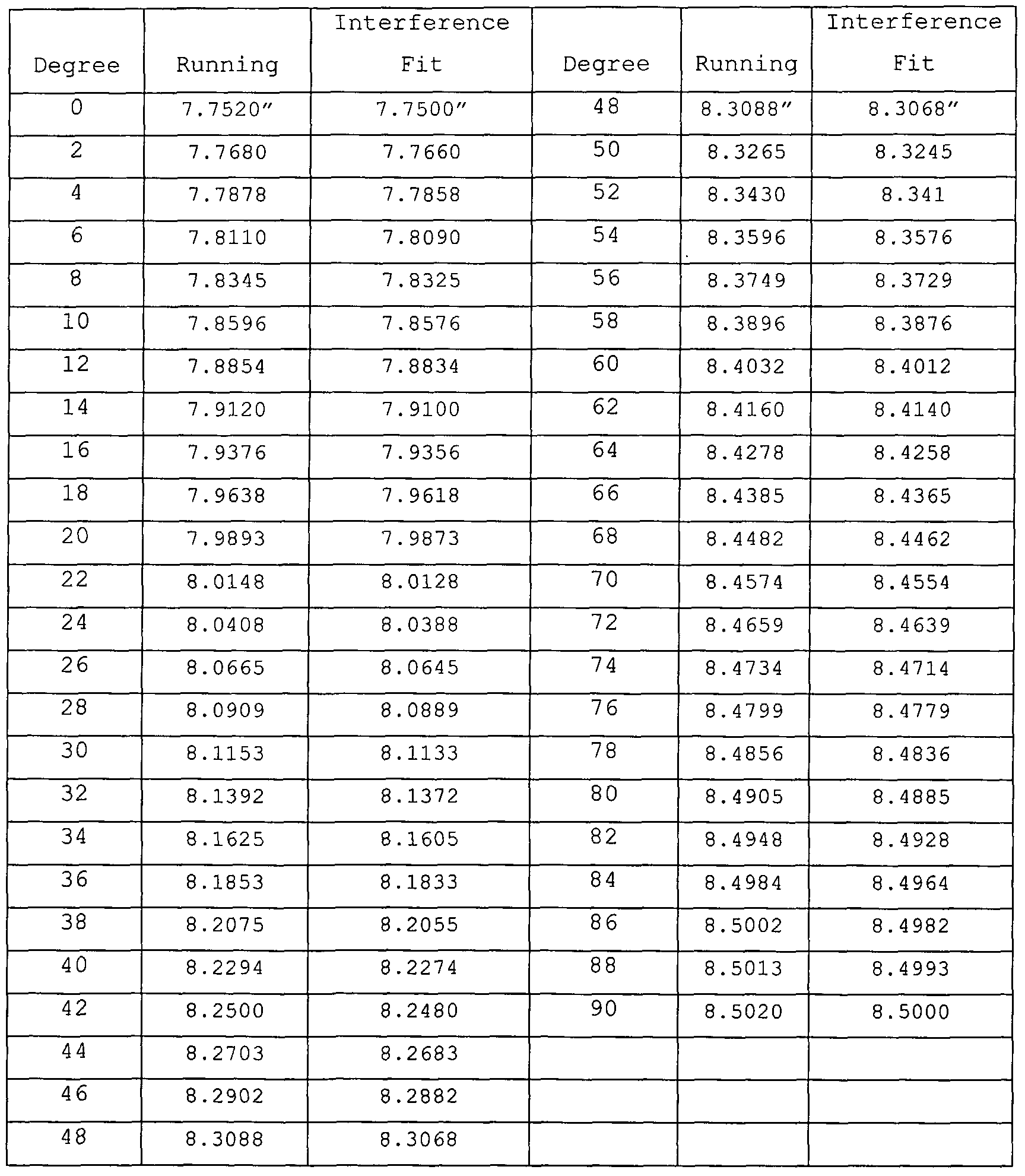
- the housing 4 when viewed in cross-section, has a profile of a spline curve.
- Tables 1 and 2 reproduced below illustrates the radius of the internal surface of the housing 4 at 2° increments through 180° (the measurements for the remaining 180° are not included because the symmetrical nature of the housing 4) .
- Radius measurements are provided for an interference fit between the elliptical bodies 22 as well for a running fit.
- the running fit includes an approximate clearance of .002 inches between the elliptical bodies 22 and the interior of the housing 4.
- the measurements assume a 1.5 inch minor axis and 3 inch major axis for the elliptical bodies 22.
- the radius of the rotor 12 is assumed to be 7.5 inches and the radius of the centers of the elliptical bodies 22 is assumed at 7 inches.
- the air/fuel charge follows behind and fills the intake sweep (i.e., region 100 in Fig. 1) .
- the air/fuel charge will be pressurized at about two atmospheres.
- the air/fuel charge then enters the compression region of the engine (i.e., region 110 in Fig. 1) .
- the combustion chamber region 120 shown in Fig. 1 which is bounded by the space between the elliptical body 22 and the pocket 20, the air/fuel charge is ignited by the ignition source 60 carried by the rotor 12.
- the ignition source 60 is ignited prior to the elliptical body 22 reaching top-dead center (e.g., early ignition) to accommodate ignition advance.
- top-dead center e.g., early ignition
- the combustion gases are exposed to the driving region 130, it is well on the way to total combustion and optimum driving pressure.
- the combustion gases are exhausted outside of the space between the rotor 12 and housing 4 via the outlet 10.
- the building pressure in the confined area does not work against the engine 2 as in a conventional piston engine.
- the elliptical body 22 actually aids in expelling combustion gases from the engine 2 via the outlet 10.
- the present engine 2 can be used in any applications where combustion engines are typically used, for example, automobiles and planes.
- the engine 2 may be used in hydrogen- powered applications.
- Multiple rotors 12 can also be used to increase the output of the engine 2.
- the present engine 2 produces motion which is entirely concentric and thus is in dynamic balance. There is no flip-flop motion associated with the rotor 12 as is present, for example, in the Wankel-type rotary combustion engines.
- the present engine 2 is able to rotate at high rates, for example, between about 25,000 and 50,000 RPM. This compares favorable with piston engines which revolve at a rate between about 4,000 and 6,000 RPM.
Landscapes
- Engineering & Computer Science (AREA)
- Mechanical Engineering (AREA)
- General Engineering & Computer Science (AREA)
- Chemical & Material Sciences (AREA)
- Combustion & Propulsion (AREA)
- Supercharger (AREA)
- Ignition Installations For Internal Combustion Engines (AREA)
Abstract
Description

Claims
Priority Applications (4)
| Application Number | Priority Date | Filing Date | Title |
|---|---|---|---|
| EP05770164.1A EP1784563B1 (en) | 2004-07-14 | 2005-07-14 | Concentric internal combustion rotary engine |
| CN2005800299544A CN101014758B (en) | 2004-07-14 | 2005-07-14 | Concentric internal combustion rotary engine |
| JP2007521644A JP4445548B2 (en) | 2004-07-14 | 2005-07-14 | Concentric internal combustion rotary engine |
| CA2573769A CA2573769C (en) | 2004-07-14 | 2005-07-14 | Concentric internal combustion rotary engine |
Applications Claiming Priority (3)
| Application Number | Priority Date | Filing Date | Title |
|---|---|---|---|
| US58794804P | 2004-07-14 | 2004-07-14 | |
| US60/587,948 | 2004-07-14 | ||
| US11/177,175 | 2005-07-08 |
Publications (2)
| Publication Number | Publication Date |
|---|---|
| WO2006019928A2 true WO2006019928A2 (en) | 2006-02-23 |
| WO2006019928A3 WO2006019928A3 (en) | 2006-09-28 |
Family
ID=35907896
Family Applications (1)
| Application Number | Title | Priority Date | Filing Date |
|---|---|---|---|
| PCT/US2005/025019 WO2006019928A2 (en) | 2004-07-14 | 2005-07-14 | Concentric internal combustion rotary engine |
Country Status (7)
| Country | Link |
|---|---|
| US (1) | US7188602B1 (en) |
| EP (1) | EP1784563B1 (en) |
| JP (1) | JP4445548B2 (en) |
| KR (1) | KR100871992B1 (en) |
| CN (1) | CN101014758B (en) |
| CA (1) | CA2573769C (en) |
| WO (1) | WO2006019928A2 (en) |
Families Citing this family (19)
| Publication number | Priority date | Publication date | Assignee | Title |
|---|---|---|---|---|
| US20080135013A1 (en) * | 2006-11-09 | 2008-06-12 | Abdalla Aref Adel-Gary | Paddling blades engine |
| JP4521785B1 (en) * | 2009-07-30 | 2010-08-11 | 清 野口 | Rotating piston machine |
| KR101163889B1 (en) | 2010-06-18 | 2012-07-09 | 현대자동차주식회사 | Planetary Gear Set for Transmission |
| US9194283B2 (en) | 2011-05-06 | 2015-11-24 | Lawrence McMillan | System and method of transducing energy from hydrogen |
| US8904992B2 (en) | 2011-05-06 | 2014-12-09 | Lawrence McMillan | Energy transducer |
| US9027345B2 (en) | 2011-07-28 | 2015-05-12 | Pratt & Whitney Canada Corp. | Compound engine system with rotary engine |
| RU2486369C1 (en) * | 2012-01-17 | 2013-06-27 | Сергей Алексеевич Уфимцев | Vacuum pump-compressor |
| JP5065532B1 (en) * | 2012-02-10 | 2012-11-07 | 泰朗 横山 | 3 cycle gas fuel engine |
| WO2013167843A2 (en) | 2012-05-10 | 2013-11-14 | William Gruet | Rotary-piston engine1 |
| WO2013184549A1 (en) * | 2012-06-05 | 2013-12-12 | WILKINSON, Cassandra, L. | Rotary energy transducer |
| CN105508041B (en) * | 2016-01-04 | 2018-09-11 | 韩照彦 | Differential rotor motor |
| CN106089698B (en) * | 2016-08-05 | 2018-09-18 | 中国石油大学(华东) | A kind of high viscous more impurity fluid media (medium) conveyings are secondary with double helix ellipse sealed engagement |
| CN106593642B (en) * | 2017-01-19 | 2021-04-13 | 龙全洪 | Flat-turning engine |
| CN106837544B (en) * | 2017-01-24 | 2019-02-12 | 顾永强 | Planetary gear engine with revolving cylinders |
| CN107489457A (en) * | 2017-09-08 | 2017-12-19 | 龙全洪 | Multifunctional engine |
| JP6410387B1 (en) * | 2018-07-10 | 2018-10-24 | オカムラ有限会社 | Rotating internal combustion engine |
| WO2020012555A1 (en) * | 2018-07-10 | 2020-01-16 | オカムラ有限会社 | Rotary internal combustion engine |
| WO2020049677A1 (en) * | 2018-09-06 | 2020-03-12 | オカムラ有限会社 | Rotating internal combustion engine |
| CN109139242A (en) * | 2018-09-19 | 2019-01-04 | 何金潜 | Tangential force engine and its core component |
Family Cites Families (21)
| Publication number | Priority date | Publication date | Assignee | Title |
|---|---|---|---|---|
| US1279912A (en) * | 1915-05-05 | 1918-09-24 | Sugar Centrifugal Discharger Company | Hydraulic device for pumping and other purposes. |
| US2136066A (en) * | 1935-05-13 | 1938-11-08 | C J Bartlett | Rotary engine |
| FR1024665A (en) * | 1950-09-16 | 1953-04-03 | Turbine with retractable blades | |
| US2947290A (en) * | 1957-11-18 | 1960-08-02 | Nsu Werke Ag | Heat generating rotary internal combustion engine |
| US3260248A (en) * | 1963-08-21 | 1966-07-12 | Samuel P Lyle | Rotary engine and method of operating same |
| DE1451716A1 (en) * | 1964-06-13 | 1969-05-29 | Georg Dirnberger | Rotary piston engine with planetary arranged runners |
| US3207425A (en) * | 1965-03-22 | 1965-09-21 | John E Morse | Rolling body engine with multiple rotors |
| US3439654A (en) * | 1967-10-10 | 1969-04-22 | Donald K Campbell Jr | Positive displacement internal combustion engine |
| US3582246A (en) * | 1969-08-15 | 1971-06-01 | Washington Scient Ind Inc | Rotary fluid displacement device |
| US3822676A (en) * | 1971-07-19 | 1974-07-09 | E Richter | Pendular piston rotary explosion engine |
| US3756755A (en) * | 1971-11-26 | 1973-09-04 | D Campbell | Rotary power device |
| US3807368A (en) * | 1972-07-21 | 1974-04-30 | R Johnson | Rotary piston machine |
| US3850150A (en) * | 1972-09-05 | 1974-11-26 | J Plevyak | Spur piston motion rotary combustion engine |
| DE2436483A1 (en) * | 1974-07-29 | 1976-02-12 | Herzner Hans | INNER AXIS ROTATING PISTON MACHINE |
| US4373484A (en) * | 1980-10-06 | 1983-02-15 | Boehling Daniel E | Rotary piston mechanism |
| IL62290A0 (en) * | 1981-03-04 | 1981-05-20 | Zielinsky A | Rotary machine |
| US4481920A (en) * | 1982-09-28 | 1984-11-13 | Pdt Development & Marketing | Rotary internal combustion engine, fluid motor and fluid pump having planetating gear pistons |
| US4726240A (en) | 1983-02-01 | 1988-02-23 | Brems John Henry | Transfer mechanism and drive with straight line lift and lower |
| US5819699A (en) * | 1997-05-13 | 1998-10-13 | Burns; William A. | Rotary internal combustion engine |
| US6955153B1 (en) * | 1999-05-13 | 2005-10-18 | Gyroton Corporation | Asymmetric compete expansion rotary engine cycle |
| US7117839B2 (en) | 2003-06-20 | 2006-10-10 | Abraham H. Horstin | Multi-stage modular rotary internal combustion engine |
-
2005
- 2005-07-08 US US11/177,175 patent/US7188602B1/en active Active
- 2005-07-14 JP JP2007521644A patent/JP4445548B2/en not_active Expired - Fee Related
- 2005-07-14 EP EP05770164.1A patent/EP1784563B1/en not_active Not-in-force
- 2005-07-14 WO PCT/US2005/025019 patent/WO2006019928A2/en active Application Filing
- 2005-07-14 KR KR1020077003411A patent/KR100871992B1/en active IP Right Grant
- 2005-07-14 CA CA2573769A patent/CA2573769C/en not_active Expired - Fee Related
- 2005-07-14 CN CN2005800299544A patent/CN101014758B/en not_active Expired - Fee Related
Non-Patent Citations (2)
| Title |
|---|
| None |
| See also references of EP1784563A4 |
Also Published As
| Publication number | Publication date |
|---|---|
| CA2573769C (en) | 2010-04-27 |
| CA2573769A1 (en) | 2006-02-23 |
| CN101014758A (en) | 2007-08-08 |
| WO2006019928A3 (en) | 2006-09-28 |
| EP1784563A4 (en) | 2009-11-18 |
| US7188602B1 (en) | 2007-03-13 |
| JP4445548B2 (en) | 2010-04-07 |
| JP2008506884A (en) | 2008-03-06 |
| KR100871992B1 (en) | 2008-12-05 |
| KR20070060078A (en) | 2007-06-12 |
| US20070068481A1 (en) | 2007-03-29 |
| CN101014758B (en) | 2012-01-04 |
| EP1784563B1 (en) | 2013-09-18 |
| EP1784563A2 (en) | 2007-05-16 |
Similar Documents
| Publication | Publication Date | Title |
|---|---|---|
| CA2573769C (en) | Concentric internal combustion rotary engine | |
| US10920662B2 (en) | Compound cycle engine | |
| US9856789B2 (en) | Compound cycle engine | |
| US9759126B2 (en) | Compound engine system with rotary engine | |
| US9057322B2 (en) | Rotary internal combustion engine | |
| US7673595B2 (en) | Rotor-piston internal combustion engine | |
| US4005682A (en) | Rotary internal combustion engine | |
| WO2016201567A1 (en) | Compound cycle engine | |
| CN218206852U (en) | Novel rotary engine structure | |
| JPS62502274A (en) | Device for driving the output shaft | |
| RU25549U1 (en) | GEAR INTERNAL COMBUSTION ENGINE | |
| CN116122957A (en) | Novel rotor engine structure and working method thereof | |
| WO2023242868A1 (en) | 360 degree combustion rotary engine with zindler curve ring gear | |
| US9273556B2 (en) | Rotary engine with rotary power heads | |
| JPS5951102A (en) | Lubricating and sealing mechanism of rotary piston engine | |
| PL214162B1 (en) | Internal combustion, two-stroke, revolving-block engine systems |
Legal Events
| Date | Code | Title | Description |
|---|---|---|---|
| AK | Designated states |
Kind code of ref document: A2 Designated state(s): AE AG AL AM AT AU AZ BA BB BG BR BW BY BZ CA CH CN CO CR CU CZ DE DK DM DZ EC EE EG ES FI GB GD GE GH GM HR HU ID IL IN IS JP KE KG KM KP KR KZ LC LK LR LS LT LU LV MA MD MG MK MN MW MX MZ NA NG NI NO NZ OM PG PH PL PT RO RU SC SD SE SG SK SL SM SY TJ TM TN TR TT TZ UA UG US UZ VC VN YU ZA ZM ZW |
|
| AL | Designated countries for regional patents |
Kind code of ref document: A2 Designated state(s): BW GH GM KE LS MW MZ NA SD SL SZ TZ UG ZM ZW AM AZ BY KG KZ MD RU TJ TM AT BE BG CH CY CZ DE DK EE ES FI FR GB GR HU IE IS IT LT LU LV MC NL PL PT RO SE SI SK TR BF BJ CF CG CI CM GA GN GQ GW ML MR NE SN TD TG |
|
| WWE | Wipo information: entry into national phase |
Ref document number: 2573769 Country of ref document: CA |
|
| WWE | Wipo information: entry into national phase |
Ref document number: 2007521644 Country of ref document: JP |
|
| NENP | Non-entry into the national phase |
Ref country code: DE |
|
| WWW | Wipo information: withdrawn in national office |
Country of ref document: DE |
|
| WWE | Wipo information: entry into national phase |
Ref document number: 1020077003411 Country of ref document: KR |
|
| WWE | Wipo information: entry into national phase |
Ref document number: 2005770164 Country of ref document: EP |
|
| WWE | Wipo information: entry into national phase |
Ref document number: 200580029954.4 Country of ref document: CN |
|
| WWP | Wipo information: published in national office |
Ref document number: 2005770164 Country of ref document: EP |