WO2005108758A1 - Air compression heat accumulating power plant with an underground heat accumulator formed in the aquifer (gaes) - Google Patents
Air compression heat accumulating power plant with an underground heat accumulator formed in the aquifer (gaes) Download PDFInfo
- Publication number
- WO2005108758A1 WO2005108758A1 PCT/LV2005/000003 LV2005000003W WO2005108758A1 WO 2005108758 A1 WO2005108758 A1 WO 2005108758A1 LV 2005000003 W LV2005000003 W LV 2005000003W WO 2005108758 A1 WO2005108758 A1 WO 2005108758A1
- Authority
- WO
- WIPO (PCT)
- Prior art keywords
- air
- aquifer
- underground
- collector
- heat
- Prior art date
- Legal status (The legal status is an assumption and is not a legal conclusion. Google has not performed a legal analysis and makes no representation as to the accuracy of the status listed.)
- Ceased
Links
Classifications
-
- F—MECHANICAL ENGINEERING; LIGHTING; HEATING; WEAPONS; BLASTING
- F02—COMBUSTION ENGINES; HOT-GAS OR COMBUSTION-PRODUCT ENGINE PLANTS
- F02C—GAS-TURBINE PLANTS; AIR INTAKES FOR JET-PROPULSION PLANTS; CONTROLLING FUEL SUPPLY IN AIR-BREATHING JET-PROPULSION PLANTS
- F02C6/00—Plural gas-turbine plants; Combinations of gas-turbine plants with other apparatus; Adaptations of gas-turbine plants for special use
- F02C6/14—Gas-turbine plants having means for storing energy, e.g. for meeting peak loads
- F02C6/16—Gas-turbine plants having means for storing energy, e.g. for meeting peak loads for storing compressed air
-
- F—MECHANICAL ENGINEERING; LIGHTING; HEATING; WEAPONS; BLASTING
- F02—COMBUSTION ENGINES; HOT-GAS OR COMBUSTION-PRODUCT ENGINE PLANTS
- F02C—GAS-TURBINE PLANTS; AIR INTAKES FOR JET-PROPULSION PLANTS; CONTROLLING FUEL SUPPLY IN AIR-BREATHING JET-PROPULSION PLANTS
- F02C7/00—Features, components parts, details or accessories, not provided for in, or of interest apart form groups F02C1/00 - F02C6/00; Air intakes for jet-propulsion plants
- F02C7/12—Cooling of plants
-
- F—MECHANICAL ENGINEERING; LIGHTING; HEATING; WEAPONS; BLASTING
- F05—INDEXING SCHEMES RELATING TO ENGINES OR PUMPS IN VARIOUS SUBCLASSES OF CLASSES F01-F04
- F05D—INDEXING SCHEME FOR ASPECTS RELATING TO NON-POSITIVE-DISPLACEMENT MACHINES OR ENGINES, GAS-TURBINES OR JET-PROPULSION PLANTS
- F05D2260/00—Function
- F05D2260/20—Heat transfer, e.g. cooling
- F05D2260/207—Heat transfer, e.g. cooling using a phase changing mass, e.g. heat absorbing by melting or boiling
-
- Y—GENERAL TAGGING OF NEW TECHNOLOGICAL DEVELOPMENTS; GENERAL TAGGING OF CROSS-SECTIONAL TECHNOLOGIES SPANNING OVER SEVERAL SECTIONS OF THE IPC; TECHNICAL SUBJECTS COVERED BY FORMER USPC CROSS-REFERENCE ART COLLECTIONS [XRACs] AND DIGESTS
- Y02—TECHNOLOGIES OR APPLICATIONS FOR MITIGATION OR ADAPTATION AGAINST CLIMATE CHANGE
- Y02E—REDUCTION OF GREENHOUSE GAS [GHG] EMISSIONS, RELATED TO ENERGY GENERATION, TRANSMISSION OR DISTRIBUTION
- Y02E60/00—Enabling technologies; Technologies with a potential or indirect contribution to GHG emissions mitigation
- Y02E60/16—Mechanical energy storage, e.g. flywheels or pressurised fluids
Definitions
- this invention relates to Classes F02C6/14; F02C6/16.
- the present invention concerns air compression heat accumulating power plant with an underground heat accumulator formed in the aquifer (GAES) (further - GAES) and is designed as a stabilising element in high-power electroenergetic systems in order to ensure high-quality functioning of these systems, their economy and safety.
- GAES underground heat accumulator formed in the aquifer
- GAES underground heat accumulator formed in the aquifer
- As one of the main tasks of the GAES in high-power electric energy systems is to equalise the daily consumption irregularity schedule by accumulating the cheap surplus of electric energy during the minimum hours of night consumption and returning it to the energy system during the peak hours.
- the GAES ensure the operation of atomic power plants (APP) and thermal power plants (TPP), which generate the basic capacities under the top optimum conditions So the GAES, working together with the NPP, ensure: increase in the efficient power of the NPP approximately 1.3 times; considerably higher safety of the NPP since there is no need to manoeuvre with the NPP capacity, and the NPP is working in a strictly optimal operating mode; ensures more complete "burning" of nuclear fuel; decreases the prime cost of the produced electric energy, extends the service life of the equipment, etc.; The above-mentioned applies also to the TPP.
- APP atomic power plants
- TPP thermal power plants
- the GAES may participate as an independent member of the market purchasing the cheap surplus of energy during the minimum consumption hours at night and in other cases and selling it during the peak hours at a considerably higher price, as well as providing other services.
- the GAES is designed for the power of 100 MW, and more, at the energy capacities of 500 MW h, and more.
- the GAES relates to the electric energy accumulation equipment in which, by means of an electrically driven air compressor (further - compressor), the electric energy is converted into air compression heat and compressed air pressure potential energies which are accumulated during the minimum consumption hours and other cases and, if necessary (during the peak hours and other cases), by means of an air turbine and a turbogenerator, are converted back to electric energy.
- This invention differs from the previously discussed analogous patents by the fact that, with an aim to increase the energy capacity and power of the GAES, and raise its CE, the air compression heat of the final section or body of the compressor is transferred into the underground heat accumulator (further - UHA) which is created in a vertically closed, porous underground aquiferous collector stratum (further - aquifer, collector aquifer) and is simultaneously a compressed air reservoir.
- the underground heat accumulator further - UHA
- aquiferous collector stratum further - aquifer, collector aquifer
- Such aquifer are widely distributed, and this enables construction of the GAES in close vicinity of major consumers (large cities, industrial centres) or generating power, which is a great advantage of the GAES over the hydro- accumulating power plants.
- the present GAES can be constructed on the basis of the collector aquifer at the depth from 150 to 700 m.
- the embodiment of the said GAES depends on the depth of the aquifer and its piesometric (internal) pressure which determines the operating pressure of the GAES and hence embodiment of the compressor and the air turbine.
- the GAES may be classified into two groups: the GAES created on the collector aquifer foundation, up to 400 m deep, and operating without intersection cooling of air, the compressor working medium being air (further - WMA), by transmitting all the air compression heat from the final compressor body into the UHA (if losses are ignored);
- the aim of this invention is not the embodiment of the compressor or the turbine, therefore the embodiment of the said GAES is described in its simplest embodiment when the air compression heat is transferred from the final compressor body immediately into the UHA without WMA intersection cooling.
- the main criteria that determine the embodiment of the compressor are its maximum allowed compressed air temperature, which cannot be higher than the melting temperature of the porous rock or its chief components of the UHA, as well as the engineering standards for heat resistance of materials attained in machine (steam turbines, etc.) building today in order to ensure lasting performance of the compressor and turbines (200 - 300 thousand hours, and more).
- a limit of the compressed air temperature today is regarded the temperature of 650 - 700°C.
- the melting temperature of the porous rock found in practice meets these requirements.
- the air compression temperature would be higher than the allowed maximum (650 - 700°C) and the compressor should be in a multiple-section embodiment with the generally-known intersection cooling heat accumulation and regeneration.
- the GAES operated with the WMA intersection cooling, intersection cooling heat accumulation and regeneration we discuss only the WMA intersection cooling heat accumulation version when the heat accumulator is created in the underground aquifer.
- the compressor embodiment without intersection cooling when the air compression heat is directly transferred from the final body of the compressor into the UHA, is the simplest and the most economical embodiment of the said GAES.
- Such an GAES in its simplest embodiment, can be constructed on the collector aquifer foundation with a piesometric pressure reaching 3.2 Mpa.
- the GAES may consist of one or several such energetic blocks.
- the GAES operation is illustrated by the following Fig.s: Fig. 1 - the block diagram of the GAES; Fig.
- Fig. 2 the structure of the point type pressure duct of the GAES;
- Fig. 3 the structure of the shaft-like pressure duct of the GAES;
- Fig. 4 the structure of the underground inlet of the point type pressure duct of the GAES and the method of its construction;
- Fig. 5 the operating schedule of the GAES;
- Fig. 6 the operating schedule of the compressors and turbine units;
- Fig. 7 the operating diagram of the UHA.
- the present GAES (Fig. 1) consists of the input-output transformer 1 which lowers voltage of the high-voltage network of the external electroenergetic system corresponding to the feeding voltage of the electric motor 3 of the compressor block 2.
- the electric motor 3 drives the axial low-pressure turbocompressor 4 and, through the muitiplicator 5, the medium-pressure centrifugal turbocompressor 6.
- the number of revolutions 3000 rev./min of the electric motor 3 is increased by means of the muitiplicator 5 from 8000 to 9000 rev./min, which is required to drive the centrifugal turbocompressor 6.
- Compressors 4 and 6, as well as the muitiplicator 5, are enclosed in the heat-insulating casings 7 in the form of a profiled cushions ensuring simultaneously high sound insulation of compressors 4 and 6, and the muitiplicator 5.
- the air is delivered into the compressor 4 from the atmosphere through the air filter 8 along the air duct 9.
- the WMA is conveyed from the outlet of the compressor 6 along the main air duct 10 through the valve 11 (the valve 12 is closed) and along the pressure ducts 13 in the collector aquifer (further pressure duct) into the underground heat accumulator (further- UHA) 14 formed in the aquifer 15.
- Fig. 1 shows conditionally that the UHA 14 is formed in a cupola-shaped collector aquifer 15.
- Such a UHA 14 analogue can be also created in horizontal or slightly inclined aquifers.
- the WMA is delivered from the UHA 14 along the pressure ducts 13 and the main air duct 10 through the valve 11 (the valve 12 is closed) and, passing through the air purification unit 16, transferred to the turbine block 17 consisting of a medium-pressure air turbine 18, a low-pressure air turbine 19, a muitiplicator 20 and a turbogenerator 21.
- the outgoing air is discharged from the turbine 19 into the atmosphere through the noise damper 22
- the task of the muitiplicator 20 is to align the 8000 - 9000 re /mm of the centripetal air turbine 18 with the 3000 rev /mm of the turbogenerator 21
- the turbines 18 and 19, as well as the muitiplicator 20 are enclosed in the heat-insulating casings 7
- the GAES operates as a stabilising factor in high-power electroenergetic systems, it has to guarantee high mobility of the compressor and turbine blocks 2 and 17, i e
- the compressor block 2 has to ensure at any time the reception, conversion and accumulation in the UHA 14 of the surplus electric energy of the system
- the turbine block 17, correspondingly has to cover any deficit of the electric energy in the system at the expense of the energy stored in the UHA 14
- Ensuring high mobility of the compressor and turbine blocks 2 and 17 is problematic due to the high temperature (650 - 700°C) of the WMA and the related thermal expansion and, respectively, appearance of
- the losses of the mechanical friction energy in the turbine block 17 are not accumulated but they only flow through the heat accumulator 26. This circumstance decreases the volume of the heat accumulator 26 by half since only the mechanical friction heat energy of the compressor block 2 is accumulated.
- the internal heating system 28 in the turbine 19 is created in such a way that it ensures circulation of the heat carrier liquid in the stator casings of the respective stages of the turbine and jet apparatus. If the internal heating system 28, which is provided in the air turbine 19, is not able to "acquire" all the amount of the accumulated heat, then it is purposeful to divide the turbine 19 between the corresponding stages into two separate bodies and to heat the WMA in the heat exchanger liquid placed between these bodies.
- high-quality, heat-resistant synthetic turbine and gear reducer oils should be used in the lubrication systems of the compressor and turbine blocks 2 and 17.
- the heat accumulator 26 may be formed in the aquifer 15 and be common for several energetic blocks.
- the use of the accumulation and regeneration system of the mechanical friction energy losses allows raising the CE of the GAES by approximately 3.5 %, and the use of this system in the GAES is an object of the present invention.
- the conventional designs of pressure ducts 13 are not fit for the transfer of air heated to 650 - 700°C to the UHA 14 for the following reasons: due to the great difference in temperatures between the pressure duct 13 (650 - 700°C) and the surrounding rock 29 (15 - 20°C), and the cyclic variations in temperature (at least twice in 24 hours) the cement block 30 which ensures the fastening of the pressure duct 13 in the surrounding rock 29 and the impermeability of the fastening would be destroyed. due to the great difference in temperatures there would be considerable losses of heat, which would affect correspondingly the CE of the GAES.
- a design of the pressure duct 13 is offered (Fig. 2) which is an object of the present invention.
- the pressure duct 13 (Fig. 2) consists of the casing tube 31 cemented by means of the cement block 30 into the surrounding rock 29.
- the casing tube 31 has a blower tube 32 in it through which the WMA is supplied to (discharged from) the UHA 14.
- the pressure duct 13 offered (Fig. 2) differs from the known ones by the features that it is formed as a thermos ensuring vacuum in the space between the casing tube 31 and the blower tube 32; that the inner surfaces of the casing tube 31 and the outer surfaces of the blower tube 32 are provided with a coating of the quality that satisfies the requirements of a thermos; that a temperature compensator 33 is provided between the casing tube 31 and the blower tube 32.
- the aim of the temperature compensator 33 is to compensate the difference in axial thermal expansion between the casing tube 31 and the blower tube 32 Vacuum in the space between the casing tube 31 and the blower tube 32 is ensured by means of the vacuum pump 34
- One of the possible embodiments of the inlet of the pressure duct 13 is shown in reference A (Fig 2)
- wedges 35 are used between the casing tube 31 and the blower tube 32 They are welded to the blower tube 32 and into the longitudinal grooves of the end of the casing tube 31 The number and length of the wedges 35 is determined by the strength calculation
- the welding spots of the wedges 35 are covered with a cap 36 which ensures impermeability at the outlet end between the casing tube 31 and the blower tube 32
- the casing tube 31 and the blower tube 32 are mounted and installed into the well simultaneously by the welding method
- the embodiment of the pressure duct 13 as a thermos prevents almost all the losses in the pressure duct 13 By maintaining the temperature of the casing tube 31 equal to the temperature of the surrounding rock 29, stable
- the GAES project can be really implemented on condition that the number of the operating pressure ducts does not greater than 30-40.
- the underground inlet structures of the point type pressure ducts commonly used in the underground gas storages do not meet these requirements because of their low permeability.
- the inlet throughput of the low-pressure duct in the known UGS structures is related to the small contact surface of the pressure duct inlet in the rock and the possible rock displacement due to the fall of the high pressure in the pressure duct inlet during the gas consumption from the storage.
- an inlet structure of the point type pressure duct 13 as well as a method of its embodiment (Fig. 4), are offered, which is an object of the present invention.
- the offered inlet structure of the point type pressure duct is formed by the following method (Fig.
- thermos point type pressure duct 13 air is delivered from the mobile compressor 40 and the air heating unit 41 , this air having the following parameters: the maximum allowable air pressure at the inlet end in the collector aquifer 15 depending on the summary pressure of the upper rock; the maximum allowable air temperature depending on the structure of the pressure duct 13, the rock melting temperature of the collector aquifer 15 and the boiling temperature of the applied rock hardening liquid.
- Liquids (at the given temperature) are used as rock hardeners that harden, or burn out, in hot air at a 700°C temperature and, by hardening (burning out) ensure a good cementation (adhesion) degree of the sand and gravel grains which, after hardening, do not dissolve in water.
- Very many organic and inorganic substances meet these requirements; of course, the rock hardener should be widely available and cheap.
- As one of such liquids used for rock hardening could be waste oil.
- the rock hardener is heated in the autoclave 42 to the above mentioned temperature and is under pressure which exceeds the air pressure of the compressor 40 in the blower tube 32, the valve 43 being shut.
- the hot air flows through the lateral apertures of the inlet end of the blower tube 32 and its open end.
- the water in the collector aquifer 15 is pushed back to the air-water front state 44; the rock temperature isotherm with a temperature a little lower than the temperature of the pumped air assumes state T
- a certain amount of pressurised heated rock hardening liquid is introduced rapidly into the blower tube 32 from the autoclave 42 by opening the valve 43; this liquid is pressed out of the blower tube 32 into the heated collector aquifer 15.
- Fig. 5 shows variations in the energy amount E during the cycles C k , C a , C t of the UHA 14 in the operating mode of the GAES as shown in Fig. 6.
- Such a schedule of the GAES operating mode would correspond to the variations in a very simplified power conditions in a conditional energetic system if cycle C k proceeds during the night minimum consumption hours from 11 p.m. till 6.30 a.m.; cycle C t takes place during the morning and evening maximum consumption hours from 7 a.m. till 10.00 and from 6 p.m. till 11. p.m.; but the basic cycle C a takes place during the day from 10 a.m. till 6 p.m.
- thermoelectric system The condition of the adiabatic process is valid if the friction heat transfer into the internal heating system 28 of the turbine 19 is ignored. In a real embodiment the above statement will not ensure complete adiabatic insulation of the thermodynamic system.
- a criterion of sufficient thermoinsulation quality (the choice of materials, thickness of thermoinsulation) is technical and economical calculations considering the interest rate of the bank credit and the high price of electric energy in the maximum consumption hours.
- the operation of compressors 4 and 6 is discussed under condition that the WMA is a real two- atom gas, the mean values of its adiabatic indices K individually for each compressor being determined by tables of the air thermodynamic properties within the temperature range of each compressor.
- the WMA enthalpy increase ⁇ h c-a is the measure of the transmitted work.
- the GAES works in a sliding-pressure mode.
- the working interval of the sliding pressure is determined as a result of complicated technical and economical calculations taking into account the peculiarities of the geological composition of the collector aquifer 15, the principles of the UHA 14 structure, the type and number of the pressure ducts 13, etc.
- the sliding-pressure mode of the GAES constitutes 10% of the maximum working pressure of the compressor 6 (3.602 MPa). Under this condition the sliding-pressure working interval of the GAES varies from 3.242 to 3.602 MPa.
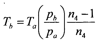
- the WMA temperature of the compressors 4 and 6 after compression T c and their theoretical work L o . a depend on the temperature T a of the environment.
- T amin 233 K(-40°C)
- P c min 3.242 MPa of the compressor 6.
- T cmax 933 K (660°C) of the compressor 6 satisfies the condition that working temperature of the compressor should not exceed 650 - 700°C by the modern machine building standards and that it should be lower than the minimum melting temperature (1710°C) of the porous rock (in our case sand and gravel mixture) of the collector stratum 14.
- the WMA enthalpy losses of the compressors 4 and 6 comprise basically the air mass leakage through the glands (3 pieces) of the outlet labyrinths of the rotor shaft end of compressors 4 and 6.
- pressure p 0.80045 MPa, which exists on the end outlet glands, this leakage will not transcend 0.1 % of the compressor power.
- the mechanical friction energy losses in the bearings of the compressors 4 and 6 are accumulated and regenerated by means of the regeneration system of the friction energy losses, and they no not influence the EC of the compressors 4 and 6.
Landscapes
- Engineering & Computer Science (AREA)
- Chemical & Material Sciences (AREA)
- Combustion & Propulsion (AREA)
- Mechanical Engineering (AREA)
- General Engineering & Computer Science (AREA)
- Structures Of Non-Positive Displacement Pumps (AREA)
- Engine Equipment That Uses Special Cycles (AREA)
Abstract
Description
Claims
Priority Applications (3)
| Application Number | Priority Date | Filing Date | Title |
|---|---|---|---|
| US11/579,290 US20080034756A1 (en) | 2004-05-08 | 2005-03-30 | Air Compression Heat Accumulating Power Plant With An Underground Heat Accumulator Formed In The Aquifer (Gaes) |
| EA200602039A EA200602039A1 (en) | 2004-05-08 | 2005-03-30 | ACCUMULATING ELECTRIC POWER STATION OF AIR COMPRESSION WITH AN UNDERGROUND BATTERY OF HEAT, WHICH IS FORMED IN WATER-MOUNTED HORIZONT (GAES) |
| EP05721986A EP1778958A1 (en) | 2004-05-08 | 2005-03-30 | Air compression heat accumulating power plant with an underground heat accumulator formed in the aquifer (gaes) |
Applications Claiming Priority (2)
| Application Number | Priority Date | Filing Date | Title |
|---|---|---|---|
| LVP-04-55 | 2004-05-08 | ||
| LVP-04-55A LV13216B (en) | 2004-05-08 | 2004-05-08 | Air pumped storage power station (gaes) |
Publications (1)
| Publication Number | Publication Date |
|---|---|
| WO2005108758A1 true WO2005108758A1 (en) | 2005-11-17 |
Family
ID=34748187
Family Applications (1)
| Application Number | Title | Priority Date | Filing Date |
|---|---|---|---|
| PCT/LV2005/000003 Ceased WO2005108758A1 (en) | 2004-05-08 | 2005-03-30 | Air compression heat accumulating power plant with an underground heat accumulator formed in the aquifer (gaes) |
Country Status (6)
| Country | Link |
|---|---|
| US (1) | US20080034756A1 (en) |
| EP (1) | EP1778958A1 (en) |
| CN (1) | CN101023253A (en) |
| EA (1) | EA200602039A1 (en) |
| LV (1) | LV13216B (en) |
| WO (1) | WO2005108758A1 (en) |
Cited By (7)
| Publication number | Priority date | Publication date | Assignee | Title |
|---|---|---|---|---|
| WO2008148962A2 (en) | 2007-05-11 | 2008-12-11 | Saipem S.A. | Installation and methods for storing and recovering electric energy |
| WO2009053593A1 (en) | 2007-10-19 | 2009-04-30 | Saipem S.A. | Installation and methods for storing and restoring electrical energy using a piston-type gas compression and expansion unit |
| WO2008074463A3 (en) * | 2006-12-18 | 2011-03-17 | Demir, Yakup | Method and device for using thermal energy, particularly for generating electric power |
| EP2594748A1 (en) | 2011-11-21 | 2013-05-22 | Siemens Aktiengesellschaft | Energy storage and recovery system comprising a thermal storage and a pressure storage |
| US8656712B2 (en) | 2007-10-03 | 2014-02-25 | Isentropic Limited | Energy storage |
| US9297277B2 (en) | 2011-09-30 | 2016-03-29 | General Electric Company | Power plant |
| CN111694388A (en) * | 2020-05-06 | 2020-09-22 | 广州地铁设计研究院股份有限公司 | Intelligent subway monitoring system and control method |
Families Citing this family (28)
| Publication number | Priority date | Publication date | Assignee | Title |
|---|---|---|---|---|
| CN101526032B (en) * | 2009-04-15 | 2012-03-21 | 武睿 | Compressed air heat-linkage energy-storage system based on reversible air engine |
| EP2435679A4 (en) * | 2009-05-27 | 2014-05-14 | Energy Compression Llc | Adsorption-enhanced compressed air energy storage |
| FR2947015B1 (en) * | 2009-06-18 | 2011-06-24 | Gdf Suez | REGULATION OF THE TEMPERATURE OF A THERMAL REGENERATOR USED IN AN ENERGY STORAGE FACILITY BY AIR ADIABATIC COMPRESSION. |
| JP2013506098A (en) * | 2009-09-23 | 2013-02-21 | レイモンド フレイジャー,スコット | System for storing compressed fluid energy in water and method of deploying the system |
| WO2011104556A2 (en) | 2010-02-24 | 2011-09-01 | Isentropic Limited | Improved heat storage system |
| GB201003105D0 (en) * | 2010-02-24 | 2010-04-14 | Isentropic Ltd | Improved heat storage system |
| CA2804910A1 (en) * | 2010-03-01 | 2011-09-09 | Brian Von Herzen | Apparatus for storage vessel deployment and method of making same |
| DE102010014588A1 (en) * | 2010-04-09 | 2010-11-18 | Voith Patent Gmbh | Power station steam and/or gas turbine drives a pump with a variable speed through a gearing with a main mechanical power output and a hydrodynamic branch |
| CA2804806C (en) | 2010-07-14 | 2018-10-30 | Bright Energy Storage Technologies, Llp | System and method for storing thermal energy |
| US8739522B2 (en) * | 2010-10-29 | 2014-06-03 | Nuovo Pignone S.P.A. | Systems and methods for pre-heating compressed air in advanced adiabatic compressed air energy storage systems |
| JP2014515339A (en) * | 2011-05-23 | 2014-06-30 | ストレワット | Device for storing and delivering fluid and method for storing and delivering compressed gas contained in such device |
| CN102839995B (en) * | 2011-06-20 | 2015-03-25 | 中国科学院工程热物理研究所 | Isothermal-isobaric compressed air energy storage system |
| DE102011112280B4 (en) | 2011-09-05 | 2022-09-29 | Fraunhofer-Gesellschaft zur Förderung der angewandten Forschung eingetragener Verein | System for storing energy using compressed air |
| US20130192216A1 (en) * | 2011-09-20 | 2013-08-01 | Light Sail Energy Inc. | Compressed gas energy storage system using turbine |
| EP2796671A1 (en) * | 2013-04-26 | 2014-10-29 | Siemens Aktiengesellschaft | Power plant system with thermochemical storage unit |
| CN103352760A (en) * | 2013-07-01 | 2013-10-16 | 中国科学院理化技术研究所 | Compressed air energy storage power generation system adopting high-temperature gas-heat combined storage device |
| CN104661350B (en) * | 2013-11-17 | 2016-11-23 | 成都奥能普科技有限公司 | Three chamber electric heat accumulators and wind-light-electricity accumulation of heat complementation power station |
| CN104265458B (en) * | 2014-07-31 | 2017-08-22 | 东南大学 | A kind of working method of compressed air energy storage power generating system |
| CN106837696A (en) * | 2015-12-03 | 2017-06-13 | 天津市石化通用机械研究所 | Wind-power electricity generation and/or compression-compressed-air-storing or comprehensive system for electric generation |
| KR102069734B1 (en) * | 2016-02-12 | 2020-01-28 | 지멘스 악티엔게젤샤프트 | Gas turbine train with starting motor |
| US11392100B2 (en) * | 2017-08-31 | 2022-07-19 | Energy Internet Corporation | Modularized energy management using pooling |
| CN109098953B (en) * | 2018-07-18 | 2020-10-27 | 同济大学 | Total regenerative compressed air energy storage method and total regenerative compressed air energy storage system |
| RU2769816C1 (en) * | 2020-11-30 | 2022-04-06 | Государственное автономное образовательное учреждение Астраханской области высшего образования Астраханский Государственный Архитектурно-Строительный Университет | Underground storage of air accumulating unit |
| CN114112713A (en) * | 2021-12-08 | 2022-03-01 | 南京航健航空装备技术服务有限公司 | A universal hydraulic product pressure test equipment |
| CN114320828B (en) * | 2021-12-13 | 2024-01-23 | 中国能源建设集团江苏省电力设计院有限公司 | A regenerative compressed air energy storage system and control method |
| US11927131B1 (en) * | 2023-01-18 | 2024-03-12 | Saudi Arabian Oil Company | Energy storage under desert environments |
| CN116519489B (en) * | 2023-07-03 | 2023-11-14 | 中能建数字科技集团有限公司 | Model test device and method for simulating deformation and damage of surrounding rock of compressed air energy storage gas storage warehouse |
| CN117722262B (en) * | 2024-02-18 | 2024-04-30 | 成都英沃信科技有限公司 | A method for using abandoned natural gas reservoir as gas circulation energy storage |
Citations (5)
| Publication number | Priority date | Publication date | Assignee | Title |
|---|---|---|---|---|
| US3677008A (en) * | 1971-02-12 | 1972-07-18 | Gulf Oil Corp | Energy storage system and method |
| US4147204A (en) * | 1976-12-23 | 1979-04-03 | Bbc Brown, Boveri & Company Limited | Compressed-air storage installation |
| US4150547A (en) * | 1976-10-04 | 1979-04-24 | Hobson Michael J | Regenerative heat storage in compressed air power system |
| JPS63208627A (en) * | 1987-02-26 | 1988-08-30 | Mitsubishi Heavy Ind Ltd | Air storage type gas turbine device |
| US20030033810A1 (en) * | 2001-08-17 | 2003-02-20 | Franz Kreitmeier | Recuperator for thermal power installation |
Family Cites Families (3)
| Publication number | Priority date | Publication date | Assignee | Title |
|---|---|---|---|---|
| US4275310A (en) * | 1980-02-27 | 1981-06-23 | Summers William A | Peak power generation |
| US6038849A (en) * | 1998-07-07 | 2000-03-21 | Michael Nakhamkin | Method of operating a combustion turbine power plant using supplemental compressed air |
| US5934063A (en) * | 1998-07-07 | 1999-08-10 | Nakhamkin; Michael | Method of operating a combustion turbine power plant having compressed air storage |
-
2004
- 2004-05-08 LV LVP-04-55A patent/LV13216B/en unknown
-
2005
- 2005-03-30 WO PCT/LV2005/000003 patent/WO2005108758A1/en not_active Ceased
- 2005-03-30 US US11/579,290 patent/US20080034756A1/en not_active Abandoned
- 2005-03-30 EA EA200602039A patent/EA200602039A1/en unknown
- 2005-03-30 EP EP05721986A patent/EP1778958A1/en not_active Withdrawn
- 2005-03-30 CN CNA2005800146801A patent/CN101023253A/en active Pending
Patent Citations (5)
| Publication number | Priority date | Publication date | Assignee | Title |
|---|---|---|---|---|
| US3677008A (en) * | 1971-02-12 | 1972-07-18 | Gulf Oil Corp | Energy storage system and method |
| US4150547A (en) * | 1976-10-04 | 1979-04-24 | Hobson Michael J | Regenerative heat storage in compressed air power system |
| US4147204A (en) * | 1976-12-23 | 1979-04-03 | Bbc Brown, Boveri & Company Limited | Compressed-air storage installation |
| JPS63208627A (en) * | 1987-02-26 | 1988-08-30 | Mitsubishi Heavy Ind Ltd | Air storage type gas turbine device |
| US20030033810A1 (en) * | 2001-08-17 | 2003-02-20 | Franz Kreitmeier | Recuperator for thermal power installation |
Non-Patent Citations (1)
| Title |
|---|
| PATENT ABSTRACTS OF JAPAN vol. 012, no. 487 (M - 778) 20 December 1988 (1988-12-20) * |
Cited By (11)
| Publication number | Priority date | Publication date | Assignee | Title |
|---|---|---|---|---|
| WO2008074463A3 (en) * | 2006-12-18 | 2011-03-17 | Demir, Yakup | Method and device for using thermal energy, particularly for generating electric power |
| WO2008148962A2 (en) | 2007-05-11 | 2008-12-11 | Saipem S.A. | Installation and methods for storing and recovering electric energy |
| JP2010527221A (en) * | 2007-05-11 | 2010-08-05 | サイペム エス.アー. | Electric energy storage return system and electric energy storage return method |
| US8627665B2 (en) | 2007-05-11 | 2014-01-14 | Saipem S.A. | Installation and method for storing and returning electrical energy |
| US8656712B2 (en) | 2007-10-03 | 2014-02-25 | Isentropic Limited | Energy storage |
| US8826664B2 (en) | 2007-10-03 | 2014-09-09 | Isentropic Limited | Energy storage |
| WO2009053593A1 (en) | 2007-10-19 | 2009-04-30 | Saipem S.A. | Installation and methods for storing and restoring electrical energy using a piston-type gas compression and expansion unit |
| JP2011501026A (en) * | 2007-10-19 | 2011-01-06 | サイペム エス.アー. | Electric energy storage and recovery system using piston type gas compression and expansion unit and electric energy storage and recovery method |
| US9297277B2 (en) | 2011-09-30 | 2016-03-29 | General Electric Company | Power plant |
| EP2594748A1 (en) | 2011-11-21 | 2013-05-22 | Siemens Aktiengesellschaft | Energy storage and recovery system comprising a thermal storage and a pressure storage |
| CN111694388A (en) * | 2020-05-06 | 2020-09-22 | 广州地铁设计研究院股份有限公司 | Intelligent subway monitoring system and control method |
Also Published As
| Publication number | Publication date |
|---|---|
| LV13216B (en) | 2005-02-20 |
| US20080034756A1 (en) | 2008-02-14 |
| EP1778958A1 (en) | 2007-05-02 |
| EA200602039A1 (en) | 2007-06-29 |
| CN101023253A (en) | 2007-08-22 |
Similar Documents
| Publication | Publication Date | Title |
|---|---|---|
| WO2005108758A1 (en) | Air compression heat accumulating power plant with an underground heat accumulator formed in the aquifer (gaes) | |
| Chen et al. | Energy and exergy analysis of two modified adiabatic compressed air energy storage (A-CAES) system for cogeneration of power and cooling on the base of volatile fluid | |
| KR102938903B1 (en) | Systems and methods for storing compressed air energy | |
| Fan et al. | Thermodynamic and applicability analysis of a hybrid CAES system using abandoned coal mine in China | |
| CN101720380B (en) | Installation and methods for storing and recovering electric energy | |
| RS64229B1 (en) | ENERGY STORAGE PLANTS AND PROCESS | |
| Lutyński | An overview of potential benefits and limitations of Compressed Air Energy Storage in abandoned coal mines | |
| WO2016012764A1 (en) | A compressed air energy storage and recovery system | |
| WO2016079485A1 (en) | A waste heat recovery system combined with compressed air energy storage | |
| JP2014509359A (en) | Compressed air energy storage system utilizing two-phase flow to facilitate heat exchange | |
| Alami | Compressed-air energy storage Systems | |
| EP4535608A1 (en) | Compressed air energy storage method | |
| CN113785112B (en) | Compressed air storage power generation device | |
| Carro et al. | Surface processes optimisation in a novel CO2-based electrothermal energy and geological storage trigeneration system | |
| US20240060602A1 (en) | Systems and methods for heat management for cased wellbore compressed air storage | |
| FR3133431A1 (en) | HEAT PUMP WITH TWO THERMAL ENERGY STORAGE AND RELEASE SYSTEMS | |
| STYS | AIR STORAGE SYSTEM ENERGY TRANSFER (ASSET)\j/cHUNTORF EXPERIENCE | |
| EP4490449B1 (en) | Heat pump having two thermal-energy storage and release systems | |
| Pottie | Adiabatic Compressed Air Energy Storage: Fundamental efficiency limits based on exergy analysis, key technology outstanding challenges and application oriented axial-flow compressor design and performance prediction | |
| Szabłowski et al. | Energy storage using underground mining caverns | |
| Wei et al. | Thermodynamics Performance and Efficiency Analysis of Compressed Air Energy Storage System Considering Gas Tightness of Gas Storage | |
| Schainker et al. | New utility scale CAES technology: performance and benefits (including CO2 benefits) | |
| Stacey et al. | Flooded mineshaft compressed air energy storage in the Witwatersrand Goldmine Complex–case study of a proposed novel energy storage method | |
| NADAU et al. | High-Temperature Heat Storage for Electricity | |
| Mdallal et al. | Developments of compressed air energy storage systems |
Legal Events
| Date | Code | Title | Description |
|---|---|---|---|
| WWE | Wipo information: entry into national phase |
Ref document number: 200580014680.1 Country of ref document: CN |
|
| AK | Designated states |
Kind code of ref document: A1 Designated state(s): AE AG AL AM AT AU AZ BA BB BG BR BW BY BZ CA CH CN CO CR CU CZ DE DK DM DZ EC EE EG ES FI GB GD GE GH GM HR HU ID IL IN IS JP KE KG KP KR KZ LC LK LR LS LT LU LV MA MD MG MK MN MW MX MZ NA NI NO NZ OM PG PH PL PT RO RU SC SD SE SG SK SL SM SY TJ TM TN TR TT TZ UA UG US UZ VC VN YU ZA ZM ZW |
|
| AL | Designated countries for regional patents |
Kind code of ref document: A1 Designated state(s): GM KE LS MW MZ NA SD SL SZ TZ UG ZM ZW AM AZ BY KG KZ MD RU TJ TM AT BE BG CH CY CZ DE DK EE ES FI FR GB GR HU IE IS IT LT LU MC NL PL PT RO SE SI SK TR BF BJ CF CG CI CM GA GN GQ GW ML MR NE SN TD TG |
|
| 121 | Ep: the epo has been informed by wipo that ep was designated in this application | ||
| WWE | Wipo information: entry into national phase |
Ref document number: 11579290 Country of ref document: US |
|
| NENP | Non-entry into the national phase |
Ref country code: DE |
|
| WWW | Wipo information: withdrawn in national office |
Ref document number: DE |
|
| WWE | Wipo information: entry into national phase |
Ref document number: 2005721986 Country of ref document: EP |
|
| WWE | Wipo information: entry into national phase |
Ref document number: 200602039 Country of ref document: EA |
|
| WWP | Wipo information: published in national office |
Ref document number: 2005721986 Country of ref document: EP |