Optisches System zur Verringerung der Reflexion optischer transparenter SubstrateOptical system for reducing the reflection of optical transparent substrates
Die Erfindung betrifft ein optisches System zur Ver- ringerung der Reflexion optisch transparenter Substrate. Dabei ist das Schichtsystem mittels auf der Oberfläche eines jeweiligen Substrates alternierend angeordneten Schichten ausgebildet, die jeweils aus einem Stoff mit kleinerer optischer Brechzahl und ei- nem zweiten Stoff mit höherer optischer Brechzahl gebildet sind, ausgebildet. Sie kann bevorzugt im Wellenlängenbereich des sichtbaren Lichtes eingesetzt werde .The invention relates to an optical system for reducing the reflection of optically transparent substrates. In this case, the layer system is formed by means of layers arranged alternately on the surface of a respective substrate, each of which is formed from a substance with a lower optical refractive index and a second substance with a higher optical refractive index. It can preferably be used in the wavelength range of visible light.
Mit der erfindungsgemäßen Lösung kann eine deutliche Reduzierung der Reflexion von einfallendem Licht an der Oberfläche des jeweiligen Substrates innerhalb eines relativ weit gefassten Wellenlängenbereiches (Spektralbereiches) erreicht werden. Außerdem ist der Einfluss unterschiedlicher Einfallswinkel des Lichtes gegenüber herkömmlichen Lösungen reduziert und es kann eine weitestgehende Farbneutralität erreicht werden. So können erfindungsgemäß beschichtete optisch transparente Substrate für die verschiedensten Applikationen eingesetzt werden. So können solcheWith the solution according to the invention, a significant reduction in the reflection of incident light on the surface of the respective substrate can be achieved within a relatively broad wavelength range (spectral range). In addition, the influence of different angles of incidence of the light is reduced compared to conventional solutions and the color can be largely neutral. Thus, optically transparent substrates coated according to the invention can be used for a wide variety of applications. Such can
Schichtsysteme beispielsweise für Brillengläser aus Glas und Kunststoffen, Abdeckungen für elektronische Anzeigeelemente (Displays) sowie auch schützende Abdeckungen bzw. Gehäuse für Kunstgegenstände einge- setzt werden.Layer systems, for example for glasses made of glass and plastics, covers for electronic display elements (displays) and also protective covers or housings for objects of art are used.
So ist es prinzipiell bekannt, Wechselschichtsysteme, die aus einzelnen Schichten, die wiederum aus Stoffen mit unterschiedlichen optischen Brechzahlen gebildet sind, zur Reduzierung von Reflexionen einfallendenIn principle, it is known to use alternating layer systems that consist of individual layers, which in turn are formed from substances with different optical refractive indices, to reduce reflections
Lichtes an Oberflächen an optisch transparenten Sub-
straten auszubilden.Light on surfaces on optically transparent sub- train straten.
Üblicherweise werden dabei die so genannten 3- Schichtsysteme MHL eingesetzt. Bei solchen Schicht- Systemen ist eine erste außen liegende Schicht L, die unmittelbar an die umgebende Atmosphäre, in der Regel Luft, angrenzt, eine Schicht, die eine kleinere optische Brechzahl, als die optische Brechzahl des jeweiligen Substrates, aufweist. Die mittlere Schicht ist aus einem Stoff, der eine größere optische Brechzahl aufweist und die M-Schicht weist eine optische Brechzahl auf, die zwischen der optischen Brechzahl des Substrates und der höheren optischen Brechzahl lieg .The so-called 3-layer systems MHL are usually used. In such layer systems, a first outer layer L, which is directly adjacent to the surrounding atmosphere, usually air, is a layer which has a lower optical refractive index than the optical refractive index of the respective substrate. The middle layer is made of a material that has a higher optical refractive index and the M layer has an optical refractive index that lies between the optical refractive index of the substrate and the higher optical refractive index.
Dabei werden für diese Einzelschichten Schichtdicken gewählt, die der optischen Dicke (Produkt aus physikalischer Dicke und optischer Brechzahl) , die 1/4 einer vorgegebenen Wellenlänge X, entsprechen, für die jeweils beiden außen liegenden Schichten eines sol- chen 3-Schichtsystemes gewählt. Die dazwischen liegende Schicht aus dem Stoff mit der höheren optischen Brechzahl wird im Gegensatz dazu mit einer optischen Dicke von 1/2 dieser Wellenlänge λ ausgebildet. Diese vorgegebene Wellenlänge ist dabei aus einem Wellen- längenintervall, in dem die Reduzierung der Reflexion des Lichtes erfolgen soll, ausgewählt worden und liegt üblicherweise im Bereich zwischen 480 und 600 nm.For these individual layers, layer thicknesses are chosen which correspond to the optical thickness (product of physical thickness and optical refractive index), which corresponds to 1/4 of a predetermined wavelength X, for the two outer layers of such a 3-layer system. In contrast, the layer between the material with the higher optical refractive index is formed with an optical thickness of 1/2 this wavelength λ. This predetermined wavelength has been selected from a wavelength interval in which the reflection of the light is to be reduced and is usually in the range between 480 and 600 nm.
In US 3,432,225 wird vorgeschlagen, anstelle eines solchen dreischichtigen Aufbaus einen dreischichtigen Ansatz zu wählen, bei dem der Schichtbereich mit der mittleren optischen Brechzahl durch anrechenbare Teile von Schichten, die aus den Stoffen mit der kleine- ren optischen Brechzahl und der größeren optischenUS Pat. No. 3,432,225 proposes to choose a three-layer approach instead of such a three-layer structure, in which the layer region with the average optical refractive index is due to parts of layers which can be counted and which consist of the substances with the lower optical refractive index and the larger optical
Brechzahl gebildet sind, ersetzt wird.
Hier werden wieder die Drei-Schichtdicken, die 1/4 einer Wellenlänge X entsprechen, ausgenutzt.Refractive index are formed, is replaced. Here again the three-layer thicknesses, which correspond to 1/4 of a wavelength X, are used.
Mit diesen so genannten klassischen Antireflexionsbe- schichtungen, die häufig auch in Kombination mit Hartschichten auf KunststoffSubstraten eingesetzt werden, können der Anteil des an den Oberflächen reflektierten sichtbaren Lichtes im Wellenlängenbereich zwischen 420 nm und 680 nm im Mittel auf ≤ 1 % reduziert werden. Dafür zeigt sich aber ein Farbeindruck in Richtung blau oder grün, der bereits bei geringfügigen Abweichungen bei der Ausbildung solcher Schichtsysteme zu Veränderungen führt, so dass es beispielsweise bei der Reparatur von Brillen erforderlich wird, beide Gläser einer Brille auszutauschen, obwohl lediglich eines ausgetauscht werden müsste .With these so-called classic antireflection coatings, which are often used in combination with hard layers on plastic substrates, the proportion of visible light reflected on the surfaces can be reduced on average to ≤ 1% in the wavelength range between 420 nm and 680 nm. However, there is a color impression in the direction of blue or green, which leads to changes even with slight deviations in the formation of such layer systems, so that it is necessary, for example when repairing glasses, to replace both glasses of a pair of glasses, although only one would have to be replaced ,
Bei den bekannten Lösungen sind solche Farbänderungen auch nachteilig, wenn unterschiedliche Lichteinfallswinkel oder Blickwinkel auftreten können. Bei Licht- einfall in schräg geneigtem Winkel erhöht sich wieder der reflektierte Anteil des Lichtes deutlich.In the known solutions, such color changes are also disadvantageous if different light incidence angles or viewing angles can occur. When light falls at an inclined angle, the reflected portion of the light increases again significantly.
Bei den bekannten Lösungen ist es außerdem problematisch, die gewünschte deutliche Reduzierung des reflektierten Anteils des jeweiligen Lichtwellenspektrums, ohne die Erzeugung eines Farbeindruckes, bei Substraten, deren optische Brechzahl relativ klein ist, zu erzielen. Dies trifft insbesondere auf Substratwerkstoffe, wie Glas und geeignete Kunststoffe, wie beispielsweise Polymethylmetacrylat oder Polycar- bonat zu, deren optische Brechzahlen im Bereich zwi- sehen 1,5 und 1,6 bei einer mittleren Wellenlänge des sichtbaren Lichtes liegen, da es nur einige wenige
ausgewählte Stoffe oder chemische Verbindungen gibt, deren optische Brechzahl kleiner als die eines solchen Substrats ist.In the known solutions, it is also problematic to achieve the desired significant reduction in the reflected portion of the respective lightwave spectrum, without producing a color impression, on substrates whose optical refractive index is relatively small. This applies in particular to substrate materials, such as glass, and suitable plastics, such as, for example, polymethyl methacrylate or polycarbonate, whose optical refractive indices are in the range between 1.5 and 1.6 at an average wavelength of visible light, since there are only a few selected substances or chemical compounds whose optical refractive index is lower than that of such a substrate.
Es ist daher Aufgabe der Erfindung, den reflektierten Anteil von einfallendem Licht in einen breiten Wellenlängenbereich des sichtbaren Lichtes, der an der Oberfläche reflektiert wird, zu reduzieren, wobei ein gezielter Einfluss auf den Wert der Reflexion selbst, auf den jeweiligen Wellenlängenbereich, in dem eine Reduzierung erreichbar ist, und/oder eine gezielte Einflussnahme und auf einen sich ergebenden Farbeindruck möglich wird.It is therefore an object of the invention to reduce the reflected portion of incident light in a wide wavelength range of visible light that is reflected on the surface, with a targeted influence on the value of the reflection itself, on the respective wavelength range in which Reduction is achievable, and / or a targeted influence and on a resulting color impression becomes possible.
Erfindungsgemäß wird diese Aufgabe mit Hilfe eines optischen Systems, wie es mit dem Anspruch 1 definiert ist, gelöst. Vorteilhafte Ausgestaltungsformen und Weiterbildungen der Erfindung können mit den in den untergeordneten Ansprüchen bezeichneten Merkmalen erreicht werden.According to the invention, this object is achieved with the aid of an optical system as defined in claim 1. Advantageous refinements and developments of the invention can be achieved with the features specified in the subordinate claims.
Das erfindungsgemäße optische Schichtsystem ist aus alternierend angeordneten Schichten eines Stoffes mit kleinerer optischer Brechzahl und Schichten höherer optischer Brechzahl gebildet.The optical layer system according to the invention is formed from alternately arranged layers of a material with a lower optical refractive index and layers with a higher optical refractive index.
Dabei werden Schichtstapel aus solchen Schichten gebildet. Diese Schichtstapel weisen dann in Bezug zu einer vorgebbaren Wellenlänge X eine äquivalente op- tische Brechzahl auf. Diese äquivalente optischeLayer stacks are formed from such layers. These layer stacks then have an equivalent optical refractive index with respect to a predeterminable wavelength X. This equivalent optical
Brechzahl ist kleiner als die optische Brechzahl des Substrates. Dabei sollte jeder Schichtstapel optische so betrachtet werden, dass er eine Einzelschicht bildet.Refractive index is less than the optical refractive index of the substrate. Each layer stack should be viewed optically so that it forms a single layer.
Die vorgebbare Wellenlänge λ kann im Wellenlängenbe-
reich liegen, in dem die reduzierte Reflektivität erreicht werden soll.The specifiable wavelength λ can be range in which the reduced reflectivity is to be achieved.
Ein einzelner solcher Schichtstapel wird aus mindestens einer Schicht H eines Stoffes mit höherer optischer Brechzahl gebildet. Diese Schicht H ist von zwei Schichten, die aus einem Stoff mit der kleineren optischen Brechzahl gebildet sind, beidseitig einge- fasst .A single layer stack of this type is formed from at least one layer H of a substance with a higher optical refractive index. This layer H is bordered on both sides by two layers which are formed from a material with the lower optical refractive index.
Dementsprechend können in einem Schichtstapel auch mehrere Schichten H eines Stoffes mit höherer optischer Brechzahl von Schichten L von beiden Seiten eingefasst sein.Accordingly, a plurality of layers H of a material with a higher optical refractive index of layers L can be enclosed from both sides in a layer stack.
Ein erfindungsgemäßes optisches Schichtsystem ist dabei aus mindestens zwei übereinander ausgebildeten Schichtstapeln ausgebildet. Dabei weisen die Schichtstapel eine sich voneinander unterscheidende äquiva- lente optische Brechzahl auf und die äquivalente optische Brechzahl der Schichtstapel verkleinert sich ausgehend vom Substrat hin zum umgebenden Medium (in der Regel Luft) .An optical layer system according to the invention is formed from at least two layer stacks formed one above the other. The layer stacks have an equivalent optical refractive index that differs from one another, and the equivalent optical refractive index of the layer stacks decreases from the substrate to the surrounding medium (usually air).
Die einzelnen Schichtstapel eines optischen Schichtsystems sollen eine optische Dicke aufweisen, die mindestens dem 2 -fachen von 1/4 der vorgebbaren Wellenlänge λ entspricht. Bevorzugt sollten sie optische Dicken aufweisen, die einem ganzzahligen Vielfachen von 1/4 der vorgebbaren Wellenlänge X entsprechen.The individual layer stacks of an optical layer system should have an optical thickness which corresponds to at least 2 times 1/4 of the predetermined wavelength λ. They should preferably have optical thicknesses which correspond to an integral multiple of 1/4 of the predefinable wavelength X.
Vorteilhaft ist es außerdem, dass sämtliche äquivalenten optischen Brechzahlen aller Schichtstapel kleiner, als die optische Brechzahl des Stoffes, aus dem die Schichten L mit kleinerer optischer Brechzahl gebildet sind, sind.
Dementsprechend reduziert sich die äquivalente optische Brechzahl von Schichtstapeln, ausgehend von der Oberfläche des Substrates bis hin zum umgebenden Me- dium schrittweise.It is also advantageous that all equivalent optical refractive indices of all layer stacks are smaller than the optical refractive index of the material from which the layers L with a lower optical refractive index are formed. Correspondingly, the equivalent optical refractive index of layer stacks is gradually reduced, starting from the surface of the substrate up to the surrounding medium.
Bei dem erfindungsgemäßen Schichtsystem können alle einzelnen Schichten H und L des gesamten Schichtsystems eine optische Schichtdicke aufweisen, die von einem ganzzahligen Vielfachen von 1/4 der vorgebbaren Wellenlänge X abweicht.In the layer system according to the invention, all of the individual layers H and L of the entire layer system can have an optical layer thickness which deviates from an integer multiple of 1/4 of the predefinable wavelength X.
Für den Fall, dass für eine einzelne Schicht, die unmittelbar auf der Oberfläche des Substrates ausgebil- det ist, ein Stoff eingesetzt worden ist, dessen optische Brechzahl kleiner, als die optische Brechzahl des Substrates ist, kann ein Teil dieser Schicht, als λ/4-Schicht für die in Rede stehende vorgegebene Wellenlänge λ ausgebildet sein.In the event that a substance whose optical refractive index is lower than the optical refractive index of the substrate has been used for a single layer which is formed directly on the surface of the substrate, part of this layer can be described as λ / 4-layer for the given wavelength λ in question.
Das erfindungsgemäße optische Schichtsystem kann vorteilhaft auf Substraten ausgebildet sein, deren optische Brechzahl ≤ 2, also auch im Bereich zwischen 1,5 und 1 , 6 ist .The optical layer system according to the invention can advantageously be formed on substrates whose optical refractive index is 2 2, that is to say also in the range between 1.5 and 1.6.
Die Schichten L, deren optische Brechzahl kleiner ist, können vorteilhaft aus Si02 oder MgF2 gebildet sein, da diese optischen Brechzahlen in jedem Fall kleiner als die optischen Brechzahlen üblicherweise verwendeter Substratwerkstoffe ist.The layers L, the optical refractive index of which is smaller, can advantageously be formed from SiO 2 or MgF 2 , since these optical refractive indices are in any case smaller than the optical refractive indices of substrate materials which are usually used.
Die Schichten H, deren optische Brechzahl größer ist, können aus Ti02, Hf02, Zr02, Ta205 und/oder Nb202, deren optische Brechzahlen n im Bereich von 1,9 bis 2,35 liegen, gebildet sein.
Die Anzahl der einzelnen Schichten, die jeweils einen einzelnen Schichtstapel bilden, kann bei drei bis sieben Schichten gewählt worden sein, wobei durch die Anzahl von Schichten für die jeweiligen Schichtstapel und dementsprechend auch der Dicke der Schichtstapel, der Wellenlängenbereich, in dem die Reflexion reduziert wird, beeinflusst werden kann.The layers H, the optical refractive index of which is larger, can be formed from Ti0 2 , Hf0 2 , Zr0 2 , Ta 2 0 5 and / or Nb 2 0 2 , the optical refractive indices n of which are in the range from 1.9 to 2.35 his. The number of individual layers, each of which forms a single layer stack, can have been selected for three to seven layers, the number of layers for the respective layer stack and accordingly also the thickness of the layer stack, the wavelength range in which the reflection is reduced , can be influenced.
Die Anzahl der Schichten sämtlicher Schichtstapel des SchichtSystems können jeweils gleich sein. Dies trifft sinngemäß auch für die optische Schichtdicke der Schichtstapel eines optischen Schichtsystems zu, die ebenfalls gleich sein kann.The number of layers of all layer stacks of the layer system can be the same in each case. This also applies analogously to the optical layer thickness of the layer stack of an optical layer system, which can also be the same.
Vorteilhaft ist es außerdem, die oberste Schicht des Schichtsystems, die unmittelbar mit dem umgebenden Medium in Kontakt steht, aus einem Stoff mit kleinerer optischer Brechzahl auszubilden. Dabei sollte diese eine optische Schichtdicke aufweisen, die grö- ßer als 1/4 der vorgegebenen Wellenlänge X ist.It is also advantageous to form the uppermost layer of the layer system, which is in direct contact with the surrounding medium, from a material with a lower optical refractive index. This should have an optical layer thickness that is greater than 1/4 of the predetermined wavelength X.
Beim erfindungsgemäßen optischen Schichtsystem können sich die Gesamtschichtdickenanteile von Schichten H, die aus einem Stoff mit größerer optischer Brechzahl gebildet sind, ausgehend von der Substratoberfläche in Richtung auf das umgebende Medium erhöhen, so dass die aufsummierten optischen Schichtdicken H in dieser Richtung gegenüber den aufsummierten optischen Schichtdicken von Schichten L oder Teilen solcher Schichten sukzessive erhöht sind.In the optical layer system according to the invention, the total layer thickness proportions of layers H, which are formed from a material with a higher optical refractive index, can increase from the substrate surface in the direction of the surrounding medium, so that the total optical layer thicknesses H in this direction compared to the total optical layer thicknesses of layers L or parts of such layers are successively increased.
Die jeweilige vorgegebene Wellenlänge λ sollte bevorzugt aus dem Wellenlängenbereich zwischen 480 und 600 nm, bevorzugt zwischen 500 und 550 nm ausgewählt sein.
Das gesamte Schichtsystem kann eine physikalische Dicke im Bereich zwischen 800 bis 3000 nm aufweisen, so dass insbesondere bei Substraten aus Kunststoffen ein verbesserter mechanischer Schutz und eine ausreichend hohe Haftfestigkeit und Kratzfestigkeit gegeben ist.The respective predetermined wavelength λ should preferably be selected from the wavelength range between 480 and 600 nm, preferably between 500 and 550 nm. The entire layer system can have a physical thickness in the range between 800 to 3000 nm, so that, in particular in the case of substrates made of plastics, there is improved mechanical protection and a sufficiently high adhesive strength and scratch resistance.
Bei den bezeichneten KunststoffSubstraten wirkt es sich außerdem vorteilhaft aus, dass ein Anteil an Schichten H, die aus einem Stoff mit höherer opti- scher Brechzahl gebildet werden müssen, für ein gesamtes optisches Schichtsystem relativ klein ist, so dass bei der Schichtausbildung im Vakuum nur eine geringfügige Substraterwärmung zu verzeichnen ist .In the case of the designated plastic substrates, it also has an advantageous effect that a proportion of layers H, which have to be formed from a material with a higher optical refractive index, is relatively small for an entire optical layer system, so that only one layer is formed in a vacuum slight substrate heating can be observed.
Die jeweilige Anzahl von Schichtstapeln und gegebenenfalls eine λ/4-Schicht aus einem Stoff mit kleinerer optischer Brechzahl, als der Substratwerkstoff, geben die Anzahl von Schritten vor, mit denen die optische Brechzahl eines optischen Schichtsystems, aus- gehend von der Substratoberfläche bis hin zum umgebenden Medium reduziert werden kann.The respective number of layer stacks and possibly a λ / 4 layer made of a material with a smaller optical refractive index than the substrate material specify the number of steps with which the optical refractive index of an optical layer system, starting from the substrate surface up to surrounding medium can be reduced.
Durch eine bestimmte Auswahl der Dicke der jeweiligen Schichtstapel, als ganzzahliges Vielfaches einer λ/4 Schichtdicke (QW) kann der Wellenlängenbereich, in dem die gewünschte reflexionsmindernde Wirkung erreicht werden kann, beeinflusst werden. So kann ein größerer Wellenlängenbereich abgedeckt werden, wenn Schichtstapel, deren optische Schichtdicke größer als das 3 -fache von 1/4, der vorgegebenen Wellenlänge ist, eingesetzt werden.The wavelength range in which the desired reflection-reducing effect can be achieved can be influenced by a specific selection of the thickness of the respective layer stack, as an integral multiple of a λ / 4 layer thickness (QW). Thus, a larger wavelength range can be covered if layer stacks whose optical layer thickness is greater than 3 times 1/4, the predetermined wavelength, are used.
Nachfolgend soll die Erfindung beispielhaft näher erläutert werden.The invention will be explained in more detail below by way of example.
Dabei zeigen:
Figur 1 ein Diagramm mit äquivalenten optischen Brechzahlen eines ersten Beispiels eines optischen SchichtSystems;Show: FIG. 1 shows a diagram with equivalent optical refractive indices of a first example of an optical layer system;
Figur 2 ein Diagramm der tatsächlichen optischen Brechzahlen innerhalb des optischen Schichtsystems ;FIG. 2 shows a diagram of the actual optical refractive indices within the optical layer system;
Figur 3 optische Brechzahlen eines optischen Schichtsystems nach erfolgter rechnerischer Optimierung;FIG. 3 optical refractive indices of an optical layer system after computational optimization;
Figur 4 ein Diagramm mit Anteilen reflektierten Lichtes innerhalb eines Wellenlängenintervalls für ein optisches Schichtsystem nach Beispiel 1 und eine entsprechend berechnete optimierte Variante dazu;FIG. 4 shows a diagram with proportions of reflected light within a wavelength interval for an optical layer system according to Example 1 and a correspondingly calculated optimized variant thereof;
Figur 5 ein Diagramm berechneter äquivalenter optischer Brechzahlen von Schichtstapeln eines optischen Systems für ein zweites Beispiel;FIG. 5 shows a diagram of calculated equivalent optical refractive indices of layer stacks of an optical system for a second example;
Figur 6 ein Diagramm mit tatsächlichen optischen Brechzahlen für ein optisches System nach Beispiel 2;FIG. 6 shows a diagram with actual optical refractive indices for an optical system according to Example 2;
Figur 7 berechnete optische Brechzahlen für ein optimiertes optisches Schichtsystem nach Bei- spiel 2;FIG. 7 calculated optical refractive indices for an optimized optical layer system according to example 2;
Figur 8 ein Diagramm des Anteils reflektierten Lichtes innerhalb eines Wellenlängenbereiches eines optischen Systems nach Beispiel 2 in ausgeführter und berechneter optimierter Form und
Figur 9 ein Diagramm, dem die Anteile an reflektiertem Licht im Wellenlängenbereich von 350 nm bis 800 nm für ein Substrat aus Po- lycarbonat mit einem Schichtsystem nach Beispiel 1 entnommen werden können.FIG. 8 shows a diagram of the proportion of reflected light within a wavelength range of an optical system according to Example 2 in an optimized and executed form and calculated FIG. 9 shows a diagram from which the proportions of reflected light in the wavelength range from 350 nm to 800 nm for a substrate made of polycarbonate with a layer system according to Example 1 can be seen.
Beispiel 1example 1
Mit dem Beispiel 1 soll eine Reduzierung der Reflexion von Licht im Wellenlängenbereich zwischen 400 bis 800 nm, die ≤ 0,4 % liegt, erreicht werden.Example 1 is intended to reduce the reflection of light in the wavelength range between 400 and 800 nm, which is ≤ 0.4%.
Das optische Schichtsystem wurde auf einem Substrat mit einer optischen Brechzahl von 1,52 ausgebildet. Es wurden Schichten L aus Si02 mit einer Brechzahl n = 1,46 und Schichten H aus Ti02 mit einer höheren optischen Brechzahl n = 2,35 ausgebildet.The optical layer system was formed on a substrate with an optical refractive index of 1.52. Layers L of SiO 2 with a refractive index n = 1.46 and layers H of TiO 2 with a higher optical refractive index n = 2.35 were formed.
Die Auslegung des optischen Schichtsystems erfolgte auf die vorgegebene Wellenlänge λ = 500 nm und es wurden insgesamt 17 solcher alternierend im Wechsel angeordneter Einzelschichten ausgebildet.The optical layer system was designed for the specified wavelength λ = 500 nm and a total of 17 such individual layers were arranged alternately.
Der Aufbau des SchichtSystems kann nachfolgender Tabelle la entnommen werden, wobei für die einzelnen Schichten L und H die jeweiligen tatsächlichen Schichtdicken d(nm), die optischen Schichtdicken n x d(nm) , die jeweiligen Verhältnisse c in Bezug zu 1/4 der vorgegebenen Wellenlänge λ. angegeben worden sind.The structure of the layer system can be found in the following table la, the individual actual layer thicknesses d (nm), the optical layer thicknesses nxd (nm) and the respective ratios c in relation to 1/4 of the predetermined wavelength λ for the individual layers L and H , have been specified.
Des Weiteren sind insgesamt fünf einzelne Schichtstapel AI bis El mit ihrer jeweiligen optischen Schicht- dicke (QW-Dicke) in Bezug zu 1/4 der vorgegebenenFurthermore, there are a total of five individual layer stacks AI to E1 with their respective optical layer thickness (QW thickness) in relation to 1/4 of the specified one
Wellenlänge λ. sowie die jeweilige äquivalente opti-
sehe Brechzahl der Schichtstapel AI bis El dabei angegeben. Dabei ist AI eine unmittelbar auf der Oberfläche des Substrates angeordnete Schicht, aus dem Stoff mit der kleineren optischen Brechzahl mit einer Schichtdicke von 1/4 der vorgegebenen Wellenlänge λ.Wavelength λ. as well as the respective equivalent opti- see refractive index of the layer stack AI to El specified. AI is a layer arranged directly on the surface of the substrate, made of the material with the smaller optical refractive index with a layer thickness of 1/4 of the predetermined wavelength λ.
Eine unmittelbar auf der Oberfläche des Substrates ausgebildete Schicht la (AI) , die aus Si02/ als Stoff mit kleinerer optischer Brechzahl ausgebildet worden ist, weist eine Dicke auf, die 1/4 der vorgegebenen Wellenlänge λ entspricht. Dies ist günstig, da Si02 eine optische Brechzahl von 1,46 aufweist, die wiederum kleiner als die optische Brechzahl des Substratwerkstoffes ist.A layer la (Al) which is formed directly on the surface of the substrate and which has been formed from SiO 2 / as a material with a lower optical refractive index has a thickness which corresponds to 1/4 of the predetermined wavelength λ. This is favorable since Si0 2 has an optical refractive index of 1.46, which in turn is smaller than the optical refractive index of the substrate material.
Mit Tabelle lb sollen die abgestuften äquivalenten Brechzahlen der Schichtstapel verdeutlicht werden.
Table 1b shows the graded equivalent refractive indices of the layer stacks.
Tabelle 1a. Beispiel 1Table 1a. example 1
Tabelle 1b Stufenbrechzahl nsk, Stufendifferenz Δns und Stapelbrechzahl nE (äquivalente Brechzahl) für Beispiel 1 , k ist die Stapelnummer.Table 1b step refractive index n sk , step difference Δn s and stack refractive index n E (equivalent refractive index) for example 1, k is the stack number.
Mit der Tabelle la wird außerdem deutlich, dass Schichten L, aus Si02 mit kleinerer optischer Brechzahl in den Schichtstapeln AI bis El Schichtdickenanteile darstellen. Dies betrifft die Schichten 1b und 5a, 5b und 9a, 9b und 13a, 13b, die an äußeren Rändern von Schichtstapeln Bl bis El angeordnet sind.Table la also shows that layers L, made of SiO 2 with a lower optical refractive index in the layer stacks AI to El represent layer thickness fractions. This applies to layers 1b and 5a, 5b and 9a, 9b and 13a, 13b, which are arranged on the outer edges of layer stacks B1 to E1.
Die äußerste Schicht 17 aus Si02 weist eine optische Schichtdicke von 143,7 nm auf, was 1,14 x 1/4 der vorgegebenen Wellenlänge X = 500 nm entspricht.The outermost layer 17 made of SiO 2 has an optical layer thickness of 143.7 nm, which corresponds to 1.14 x 1/4 of the predetermined wavelength X = 500 nm.
Die einzelnen Schichtdicken und die Schichtstapel wurden wie folgt bestimmt:The individual layer thicknesses and the layer stacks were determined as follows:
Schritt 1.Step 1.
Es wird eine Zahl q vorgegeben, die die Anzahl der einzusetzenden Schichtstapel bestimmt.A number q is specified which determines the number of layer stacks to be used.
Schritt 2.Step 2.
Es wird eine Restreflexion R0 definiert, die bei der vorgegebenen Wellenlänge X erreicht werden soll. Mit diesem Wert und der Brechzahl des umgebenden Mediums n0 wird eine Zielbrechzahl n0τ bestimmt nachA residual reflection R 0 is defined which is to be achieved at the predetermined wavelength X. A target refractive index n 0 τ is determined using this value and the refractive index of the surrounding medium n 0
Schritt 3.Step 3.
Die Differenz der Substratbrechzahl ns und der Zielbrechzahl noτ wird durch q geteilt und mit dieser Differenz werden neue Stufenbrechzahlen nsk gebildet
nachThe difference between the substrate refractive index n s and the target refractive index n oτ is divided by q, and new step refractive indexes n sk are formed with this difference to
Δns = -(ns - noτ ) q
Δn s = - (n s - n oτ ) q
mit k = l...q als Index der Stufen und mit nso = ns undwith k = l ... q as the index of the levels and with n so = n s and
Schritt 4 .Step 4.
Für jede Stufe wird je ein Schichtstapel berechnet, dessen optische Schichtdicke dem ein- bis fünffachen von 1/4 der vorgegebenen Wellenlänge λ entsprechen sollte, wobei jeder Schichtstapel einer äquivalenten Brechzahl entspricht, die nachA layer stack is calculated for each stage, the optical layer thickness of which should correspond to one to five times 1/4 of the predetermined wavelength λ, each layer stack corresponding to an equivalent refractive index, which according to
n Ek = •f Λ/nSk_ι n Skn Ek = • f Λ / n Sk _ ι n Sk
berechnet wird.is calculated.
Schritt 5.Step 5.
Ist die äquivalente Brechzahl des ersten Schichtsta- pels annähernd gleich der Brechzahl des niedrigbrechenden Stoffes L, wird der erste Schichtstapel mit nur einer λ./4-Schicht (d.i. eine Schicht, deren optische Dicke gleich 1/4 einer vorgegebenen Wellenlänge λ ist) des Stoffes mit der kleinen optischen Brech- zahl gebildet.
Schritt 6 .If the equivalent refractive index of the first layer stack is approximately equal to the refractive index of the low refractive index material L, the first layer stack will have only one λ. / 4 layer (ie a layer whose optical thickness is 1/4 of a predetermined wavelength λ) Fabric with the small optical refractive index. Step 6.
Aus der Brechzahl dieser Schicht und des Substrates wird eine neue Brechzahl nSι der ersten Substratstufe gebildet nachA new refractive index n S of the first substrate stage is formed from the refractive index of this layer and the substrate
Anschließend wird wieder nach Schritt 3 und 4 verfah- ren.Then proceed again according to steps 3 and 4.
Schritt 7.Step 7.
Von Vorteil für den Verlauf der Restreflexion kann es sein, den linearen Zusammenhang der gestuften äquivalenten Brechzahlen nach Schritt 3 statt in einem Schritt in mehreren Schritten vorzunehmen.It can be advantageous for the course of the residual reflection to carry out the linear relationship of the graduated equivalent refractive indices after step 3 instead of in one step in several steps.
Beispiel 1: Zuerst wird die erste äquivalente Brechzahl des Stoffes mit der kleineren Brechzahl bestimmt. Danach werden alle weiteren gestuften äquivalenten Brechzahlen nach dem linearen Zusammenhang aus Schritt 3 bestimmt.Example 1: First, the first equivalent refractive index of the substance with the lower refractive index is determined. Then all other graded equivalent refractive indices are determined according to the linear relationship from step 3.
Beispiel 2 : Zuerst wird die erste äquivalente Brechzahl wieder durch die Brechzahl des Stoffes mit der kleineren Brechzahl bestimmt. Danach werden nur zwei weitere gestufte äquivalente Brechzahlen bestimmt und im Anschluss daran
die restlichen beiden äquivalenten optischen Brechzahlen.Example 2: First, the first equivalent refractive index is determined by the refractive index of the substance with the lower refractive index. After that, only two further graded equivalent refractive indices are determined and then the remaining two equivalent optical refractive indices.
Schritt 8.Step 8
Je nach gewünschter Bandbreite des Reflexionsbereiches werden für die Schichtstapel optische Schichtdicken gewählt, die einem drei-, vier- oder fünffachen von 1/4 der vorgegebenen Wellenlänge X entsprechen.Depending on the desired bandwidth of the reflection area, optical layer thicknesses are selected for the layer stack, which correspond to three, four or five times 1/4 of the predetermined wavelength X.
Schritt 9.Step 9
Bei Schichtstapeln, die eine optische Schichtdicke aufweisen, die dem dreifachen von einem 1/4 der vor- gegebenen Wellenlänge X entspricht, die die gewünschte äquivalente Brechzahl aufweisen und aus drei Schichten gebildet sind, dabei deren erste und dritte eine L Schicht und deren mittlere Schicht eine H Schicht sind, werden die optischen Schichtdicken der Schichten nach der Formel berechnet:In the case of layer stacks which have an optical layer thickness which corresponds to three times a 1/4 of the predetermined wavelength X, which have the desired equivalent refractive index and are formed from three layers, their first and third an L layer and their middle layer are an H layer, the optical layer thicknesses of the layers are calculated according to the formula:
wobei die beiden L-Schichten identisch sind und π ist
Schritt 10 .where the two L layers are identical and is π Step 10.
Für jede äquivalente Brechzahl (eines Schichtstapels mit einer optischen Schichtdicke, die dem dreifachen von 1/4 der vorgegebenen Wellenlänge X entspricht) werden die zugehörigen optischen Dicken nach Schritt 9 bestimmt.For each equivalent refractive index (of a layer stack with an optical layer thickness that corresponds to three times 1/4 of the predetermined wavelength X), the associated optical thicknesses are determined according to step 9.
Schritt 11.Step 11.
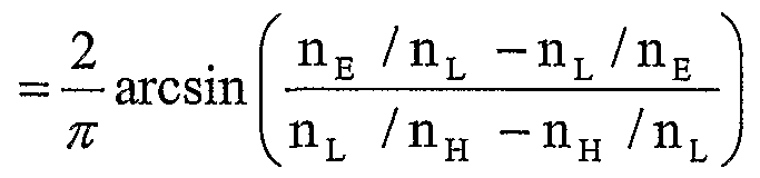
Bei Schichtstapeln mit einer optischen Schichtdicke, die dem vierfachen von 1/4 der vorgegebenen Wellenlänge X entspricht, wird die entsprechende äquivalente Brechzahl mit fünf Schichten gebildet, deren erste, dritte und fünfte L Schichten und deren zweite und vierte Schicht H Schichten sind. Die optischen Schichtdicken werden nach den Formeln berechnet :In the case of layer stacks with an optical layer thickness that corresponds to four times 1/4 of the predetermined wavelength X, the corresponding equivalent refractive index is formed with five layers, the first, third and fifth L layers and the second and fourth layers of which are H layers. The optical layer thicknesses are calculated according to the formulas:
2_ cm = — arcsinl nL ns - ns nL π n L / nH - nH / nL 2_ c m = - arcsinl n L n s - n s n L π n L / n H - n H / n L
mit den Hilfsbrechzahlen nA und nB, die berechnet
werden nachwith the auxiliary refractive indices nA and nB that calculated are after
mit x = nL(n0 +ns)(nL ~n E) 2nE(nE +ns)with x = n L (n 0 + n s ) (nL ~ n E ) 2n E (n E + n s )
und n4 L nsnE and n 4 L n s n E
Die optischen Schichtdicken der einzelnen Schichten ergeben sich dann zuThe optical layer thicknesses of the individual layers then result in
Cl (L) = 1 + CLA Cl (L) = 1 + C LA
C2(H) = CHAC2 (H) = CHA
C3 (L) = CLA + cLB C3 (L) = C LA + c LB
C4(H) = cHB C5(L) = 1 + cLB C4 (H) = c HB C5 (L) = 1 + c LB
Schritt 12.Step 12.
Schritt 11 wird für jede äquivalente Brechzahl der Schichtstapel ausgeführt, wobei die Brechzahlen nE, ns und n0 entsprechend durch die laufenden Werte nEk, -jk-x bzw. nSk nach Schritt 3 und 4 zu ersetzen sind.Step 11 is carried out for each equivalent refractive index of the layer stacks, the refractive indices n E , n s and n 0 being replaced by the current values n Ek , -j k -x and n Sk according to steps 3 and 4, respectively.
Dadurch reduziert sich die absolute Gesamtanzahl der tatsächlich auszubildenden Schichten eines solchen optischen Schichtsystems von 21 auf praktisch 17.As a result, the absolute total number of layers of such an optical layer system to be actually formed is reduced from 21 to practically 17.
Die Schichtstapel AI bis El sind jeweils aus fünf Schichten aus jeweils alternierend angeordneten Si02
als L-Schichten und Ti02 als H-Schichten ausgebildet.The layer stacks AI to E1 are each composed of five layers of alternating Si0 2 formed as L layers and Ti0 2 as H layers.
Wie mit Figur 4 gezeigt, kann eine deutliche Reduzierung des reflektierten Anteils an Licht im Wellenlän- genbereich zwischen 400 und 800 nm mit einem solchen optischen Schichtsystem, wie es mit Beispiel 1 definiert worden ist, erreicht werden. Durch eine rechnerische Nachoptimierung (refinement) dieses Schichtsystems konnte das Reflexionsverhalten, wie mit der dickeren Linie dargestellt, über den bezeichneten Wellenlängenbereich vergleichmäßigt, und zumindest teilweise zusätzlich noch reduziert werden, da die realen optischen Brechzahldispersionen berücksichtigt werden können. Sie vorab berechneten Schichtdicken veränderten sich dabei nur unwesentlich (s. Figur 3) .As shown in FIG. 4, a significant reduction in the reflected portion of light in the wavelength range between 400 and 800 nm can be achieved with such an optical layer system as has been defined in Example 1. By means of computational re-optimization (refinement) of this layer system, the reflection behavior, as shown with the thicker line, could be made more uniform over the specified wavelength range, and at least partially reduced, since the real optical refractive index dispersions can be taken into account. The layer thicknesses calculated beforehand changed only insignificantly (see FIG. 3).
Beispiel 2Example 2
Mit einem optischen Schichtsystem für ein Beispiel 2 soll der Anteil an reflektiertem Licht im Wellenlängenbereich zwischen 450 nm bis 570 nm auf unterhalb 0,1 % gesenkt werden.With an optical layer system for example 2, the proportion of reflected light in the wavelength range between 450 nm to 570 nm is to be reduced to below 0.1%.
Auch hier wurde ein Substrat, das eine optische Brechzahl von 1,52 aufwies, mit einem entsprechend diesem Beispiel ausgebildeten erfindungsgemäßen optischen SchichtSystem versehen. Es wurden wieder alternierend wechselnd angeordnete Schichten L, aus Si02 und Schichten H aus Ti02 ausgebildet .Here too, a substrate which had an optical refractive index of 1.52 was provided with an optical layer system according to the invention designed in accordance with this example. Layers L made of SiO 2 and layers H made of TiO 2 were alternately arranged alternately.
Der Aufbau des optischen Schichtsystems nach diesem Beispiel 2 ergibt sich mit nachfolgender Tabelle 2a. Die Tabelle 2b verdeutlicht wieder die Abstufungen äquivalenter Brechzahlen, was in Figur 5 schematisch verdeutlicht wird.
Tabelle 2a. Beispiel 2The structure of the optical layer system according to this example 2 is shown in Table 2a below. Table 2b again shows the gradations of equivalent refractive indices, which is shown schematically in FIG. 5. Table 2a. Example 2
Tabelle 2b. Stufenbrechzahl nsk, Stufendifferenz Δns und Stapelbrechzahl nE (äquivalente Brechzahl) für Beispiel 2, k ist die Stapelnummer.Table 2b. Step refractive index n sk , step difference Δn s and stack refractive index n E (equivalent refractive index) for example 2, k is the stack number.
Es wird deutlich, dass bei diesem Schichtsystem wieder fünf übereinander ausgebildete Schichtstapel A2 bis E2 ausgebildet worden sind, wobei in jedem der Schichtstapel lediglich eine Schicht H aus Ti02 ange- ordnet ist. Eine solche Schicht H i st wiederum von beiden Seiten mit Schichten L aus S i02 eingefasst . Insgesamt wurden 9 Schichten ausgebildet. Die Schichten lb und 3a, 3b und 5a, 5b und 7a , 7b stellen Schichtdickenanteile von Schichten L, aus einem Stoff mit kleinerer optischer Brechzahl, dar.It is clear that five layer stacks A2 to E2 formed above one another have again been formed in this layer system, only one layer H made of TiO 2 being arranged in each of the layer stacks. Such a layer H is in turn bordered on both sides with layers L of S i0 2 . A total of 9 layers were formed. The layers 1b and 3a, 3b and 5a, 5b and 7a, 7b represent layer thickness portions of layers L, made of a material with a lower optical refractive index.
Bei der Auslegung dieses optischen Schichtsystems nach Beispiel 2 wurde wieder von einer vorgegebenen Wellenlänge λ. = 500 nm ausgegangen.When designing this optical layer system according to Example 2, λ was again of a predetermined wavelength. = 500 nm assumed.
Die Auslegung der Schichtdicken und Schichtstapel wurde, wie beim Beispiel 1 bestimmt .The design of the layer thicknesses and layer stacks was determined as in Example 1.
Die Anteile an reflektiertem Licht im Wellenlangenbe- reich zwischen 450 und 570 nm sind für das optische Schichtsystem nach Beispiel 2 mit der dünn dargestellten Linie Figur 8 entnehmbar. Die dick nachgezogene Linie ergibt den erreichbaren Anteil reflektierten Lichtes unter Berücksichtigung einer durch Be- rechnung erreichten nachträglichen Optimierung des Beispiels. Bei einer solchen Nachoptimierung können variable optische Eigenschaften, der die jeweiligen Schichten bildenden Stoffe berücksichtigt werden. Die, wie vorab erläutert, bestimmten Schichtdicken müssen dabei nur geringfügig verändert werden.The proportions of reflected light in the wavelength range between 450 and 570 nm can be seen for the optical layer system according to Example 2 with the thin line shown in FIG. 8. The thick line shows the achievable proportion of reflected light, taking into account a subsequent optimization of the example achieved by calculation. With such a post-optimization, variable optical properties of the substances forming the respective layers can be taken into account. The layer thicknesses determined, as explained above, need only be changed slightly.
Nachfolgend soll eine Möglichkeit zur Ausbildung eines optischen SchichtSystems zur Reduzierung des reflektierten Anteils an Licht auf einem optischen Fenster aus transparentem Polycarbonat erläutert werden. Ein solches Fenster kann beispielsweise eine Ab-
deckung für ein elektronisches Anzeigeelement in Kraftfahrzeugen sein. Es soll mit einem solchen optischen Fenster bei einem Einfallswinkel von 60° des Lichtes kein roter Farbeindruck auftreten.A possibility of forming an optical layer system for reducing the reflected portion of light on an optical window made of transparent polycarbonate will be explained below. Such a window can, for example, cover for an electronic display element in motor vehicles. With such an optical window, there should be no red color impression at an angle of incidence of 60 ° of the light.
Das optische Schichtsystem wies eine Gesamtdicke von 1600 nm auf und es wurden wiederum alternierend wechselnd Schichten aus Si02 und Ti02 durch Elektronen- Strahlverdampfung abgeschieden. Bei der Abscheidung im Vakuum wurde die jeweilige Schicht mit Argonionen, die eine Energie von 80 eV (Si02) und 120 eV (Ti02) aufweisen, bei einer Stromdichte von ca. 0,1 mA/cm2 beschossen.The optical layer system had a total thickness of 1600 nm and layers of SiO 2 and TiO 2 were alternately deposited alternately by electron beam evaporation. During the vacuum deposition, the respective layer was bombarded with argon ions, which have an energy of 80 eV (Si0 2 ) and 120 eV (Ti0 2 ), at a current density of approx. 0.1 mA / cm 2 .
Es wurde ein Schichtaufbau gewählt, wie er dem Beispiel 1, das vorab beschrieben worden ist, entspricht. Dabei wurde eine Nachoptimierung der jeweiligen Schichtdicken unter Berücksichtigung der jeweiligen realen optischen Brechzahldispersionen vorge- nommen .A layer structure was selected as it corresponds to Example 1, which has been described above. The respective layer thicknesses were re-optimized taking into account the respective real optical refractive index dispersions.
Der reflektierte Anteil konnte im Wellenlängenbereich zwischen 380 nm bis 770 nm unterhalb 1 % gehalten werden, wie dies dem in Figur 9 gezeigten Diagramm entnommen werden kann.The reflected portion could be kept below 1% in the wavelength range between 380 nm to 770 nm, as can be seen from the diagram shown in FIG. 9.
Die Transparenz im Wellenlängenbereich des sichtbaren Lichtes konnte auf 98 % bei einer beidseitigen Ausbildung eines optischen Schichtsystems auf dem opti- sehen Fenster, als Substrat, gegenüber 92 % bei einer einseitigen Beschichtung erhöht werden.The transparency in the wavelength range of visible light could be increased to 98% when an optical layer system was formed on both sides of the optical window, as a substrate, compared to 92% with a one-sided coating.
Bei in einem schräg geneigten Winkel einfallendem Licht war ein leicht grünlicher Farbeindruck zu ver- zeichnen. Bei senkrechtem Lichteinfall wurde Farbneutralität erreicht.
Das auf dem Polycarbonat -Substrat ausgebildete optische System widerstand dem Abriebtest nach ISO 9211- 02-04 ohne Defektbildung sowie einen Abriebtest mit Stahlwolle. Die Kratzfestigkeit des Polycarbonat- Substrates konnte so gegenüber dem unbeschichteten Substratwerkstoff deutlich erhöht werden.
When the light came in at an obliquely inclined angle, there was a slightly greenish color impression. Color neutrality was achieved with perpendicular incidence of light. The optical system formed on the polycarbonate substrate withstood the abrasion test according to ISO 9211-02-04 without defects and an abrasion test with steel wool. The scratch resistance of the polycarbonate substrate was significantly increased compared to the uncoated substrate material.