WO2005011144A2 - Method and device for estimating a propagation channel of a multicarrier signal - Google Patents

Method and device for estimating a propagation channel of a multicarrier signal Download PDF

Info

Publication number
WO2005011144A2
WO2005011144A2 PCT/FR2004/001900 FR2004001900W WO2005011144A2 WO 2005011144 A2 WO2005011144 A2 WO 2005011144A2 FR 2004001900 W FR2004001900 W FR 2004001900W WO 2005011144 A2 WO2005011144 A2 WO 2005011144A2
Authority
WO
WIPO (PCT)
Prior art keywords
propagation channel
estimating
pilots
channel according
estimate
Prior art date
Application number
PCT/FR2004/001900
Other languages
French (fr)
Other versions
WO2005011144A3 (en
Inventor
Bruno Jahan
Pierrick Louin
Original Assignee
Tdf
Priority date (The priority date is an assumption and is not a legal conclusion. Google has not performed a legal analysis and makes no representation as to the accuracy of the date listed.)
Filing date
Publication date
Application filed by Tdf filed Critical Tdf
Priority to EP04767724.0A priority Critical patent/EP1661348B1/en
Priority to US10/564,866 priority patent/US8094732B2/en
Priority to CN2004800207656A priority patent/CN1826785B/en
Publication of WO2005011144A2 publication Critical patent/WO2005011144A2/en
Publication of WO2005011144A3 publication Critical patent/WO2005011144A3/en

Links

Classifications

    • HELECTRICITY
    • H04ELECTRIC COMMUNICATION TECHNIQUE
    • H04LTRANSMISSION OF DIGITAL INFORMATION, e.g. TELEGRAPHIC COMMUNICATION
    • H04L25/00Baseband systems
    • H04L25/02Details ; arrangements for supplying electrical power along data transmission lines
    • H04L25/0202Channel estimation
    • H04L25/0224Channel estimation using sounding signals
    • H04L25/0228Channel estimation using sounding signals with direct estimation from sounding signals
    • H04L25/023Channel estimation using sounding signals with direct estimation from sounding signals with extension to other symbols
    • H04L25/0232Channel estimation using sounding signals with direct estimation from sounding signals with extension to other symbols by interpolation between sounding signals
    • HELECTRICITY
    • H04ELECTRIC COMMUNICATION TECHNIQUE
    • H04LTRANSMISSION OF DIGITAL INFORMATION, e.g. TELEGRAPHIC COMMUNICATION
    • H04L25/00Baseband systems
    • H04L25/02Details ; arrangements for supplying electrical power along data transmission lines
    • H04L25/0202Channel estimation
    • H04L25/022Channel estimation of frequency response
    • HELECTRICITY
    • H04ELECTRIC COMMUNICATION TECHNIQUE
    • H04LTRANSMISSION OF DIGITAL INFORMATION, e.g. TELEGRAPHIC COMMUNICATION
    • H04L27/00Modulated-carrier systems
    • H04L27/0014Carrier regulation
    • H04L2027/0024Carrier regulation at the receiver end
    • H04L2027/0026Correction of carrier offset
    • H04L2027/003Correction of carrier offset at baseband only
    • HELECTRICITY
    • H04ELECTRIC COMMUNICATION TECHNIQUE
    • H04LTRANSMISSION OF DIGITAL INFORMATION, e.g. TELEGRAPHIC COMMUNICATION
    • H04L27/00Modulated-carrier systems
    • H04L27/0014Carrier regulation
    • H04L2027/0083Signalling arrangements
    • H04L2027/0089In-band signals
    • H04L2027/0093Intermittant signals
    • HELECTRICITY
    • H04ELECTRIC COMMUNICATION TECHNIQUE
    • H04LTRANSMISSION OF DIGITAL INFORMATION, e.g. TELEGRAPHIC COMMUNICATION
    • H04L27/00Modulated-carrier systems
    • H04L27/26Systems using multi-frequency codes
    • H04L27/2601Multicarrier modulation systems
    • H04L27/2647Arrangements specific to the receiver only
    • H04L27/2655Synchronisation arrangements
    • H04L27/2657Carrier synchronisation

Definitions

  • the field of the invention is that of applied digital communications, over-the-air digital broadcasting systems, of the type belonging to the group comprising DAB, DVB-T, DRM, but also telecommunications (ADSL, Hyperlan2, etc.). More specifically, the invention relates to receivers of the DAB, DVB-T, DRM type which use OFDM demodulation (“Orthogonal Frequency Division Multiplex” in English, for “Multiplexing by orthogonal frequency division”), which is more and more used in the aforementioned fields. 2.
  • OFDM demodulation Orthogonal Frequency Division Multiplex
  • OFDM modulation consists in distributing in time / frequency space data of duration Tu (said useful symbol time) over a plurality of carrier frequencies modulated independently, for example in QPSK or QAM.
  • the OFDM thus cuts the channel into cells along the axes of time 11 and frequencies 12, as illustrated in FIG. 1.
  • Each of the carriers is orthogonal to the previous one.
  • the channel of predetermined length 13 then consists of a series of frequency sub-bands 14 and a series of time segments 15.
  • Each frequency / time cell is assigned a dedicated carrier. We will therefore distribute the information to be transported over all of these carriers, each modulated at low speed for example, by QPSK or QAM type modulation.
  • An OFDM symbol includes all of the information carried by all of the carriers at an instant t.
  • This modulation technique is particularly effective in situations where multi-paths are encountered.
  • FIG. 2 which presents a set of OFDM symbols 21
  • the same series of symbols arriving at a receiver by two different paths is presented as the same information arriving at two different moments and which add up.
  • These echoes cause two types of defects: intra-symbol interference: addition of a symbol with itself slightly out of phase; - inter-symbol interference: addition of a symbol with the next plus the slightly out-of-step previous.
  • a “dead” zone called the guard interval 22 is inserted, the duration 23 of which is chosen to be sufficiently large in relation to the spread of the echoes.
  • pilot synchronization carriers (of amplitude often greater than the payload carriers) are inserted.
  • the value and location of these pilots in time / frequency space are predefined and known to the receivers. After an interpolation in time and frequencies, one obtains an estimate of the response of the channel more or less relevant according to the number of reference pilots and their distribution in the time / frequency domain.
  • AM bands OFDM modulation
  • DRM digital radio in the AM bands
  • the receivers used for OFDM demodulation essentially use the channel response calculated from the reference pilots. The the accuracy of this estimate therefore depends on the proportion of reference pilots inserted in the OFDM symbols.
  • an objective of the invention is to provide a method and a device making it possible to optimize the estimation of a propagation channel, in particular of an OFDM channel, for example for applications of the DRM type.
  • an additional objective of the invention is to combat the strong fainting that can be encountered, for example in the case of DRM.
  • Another objective of the invention is to provide a method and a device making it possible to correct the reference pilots as a function of a corresponding propagation channel.
  • An additional objective of the invention is to provide an estimation method and device making it possible to refine the synchronization of the receivers.
  • Another objective of the invention is to provide a method and a device which are easy to implement, while remaining of reasonable cost.
  • a final objective of the invention is to provide a method and a device which also corrects the problem of the common phase error on an OFDM signal on reception, induced for example by the phase noises of the oscillators, in addition to the error common to OFDM symbols on amplitude. 4.
  • MAIN CHARACTERISTICS OF THE INVENTION are achieved using a method for estimating a propagation channel formed by successive symbols of a multicarrier signal comprising each at least at least one reference pilot, and a plurality of frequencies carrying data.
  • Such a method advantageously comprises at least one step of correcting the reference pilot or pilots, as a function of a first estimate of a propagation channel, so as to deliver a second, more precise estimate of the channel.
  • This approach is based in particular on the observation made by the inventors that the algorithms currently known among the solutions of the prior art do not use all the information that it is possible to extract from reference pilots.
  • the article entitled "The effect of phase noise in COFDM” or “the effect of phase noise in COFDM” published in 1998 in the review "EBU Technical Review” by J. Scott identifies the problem of common phase error on an OFDM signal on reception, induced for example by the phase noises of the oscillators. This article of the prior art does not, however, propose any correction to this problem.
  • this first step of estimating a propagation channel takes account of the pilots received before they are corrected.
  • the correction step comprises a step of calculating an amplitude and / or phase error vector, for each of the reference pilots.
  • the step of calculating an error vector implements an averaging of a set of error vectors obtained on at least one symbol. This averaging can correspond, for example, to an integration on the error vectors obtained for each of the symbols, so as to eliminate any risk of noise introduction that could be caused by taking into account atypical pilots.
  • the averaging is calculated on each symbol.
  • the set of error vectors comprises only the error vectors meeting at least one predetermined quality criterion.
  • the step of calculating an amplitude and / or phase error vector comprises a preliminary step of rejecting, for this calculation, pilots whose amplitude is less than a first predetermined minimum average threshold. and / or greater than a second predetermined maximum average threshold, so as to avoid any risk of introducing bias in the calculation of the amplitude and / or phase error vector.
  • a preliminary step of rejecting, for this calculation pilots whose amplitude is less than a first predetermined minimum average threshold. and / or greater than a second predetermined maximum average threshold, so as to avoid any risk of introducing bias in the calculation of the amplitude and / or phase error vector.
  • the method according to the invention makes it possible to demodulate all the pilots in order to extract therefrom a common estimate applicable to the channel, by applying the estimation of the channel to the data themselves.
  • the second estimate includes an equalization step, as a function of the first estimate of the channel.
  • the equalization step is carried out on all of the carrier frequencies of each of the symbols.
  • the equalization step is followed by a step of calculating an impulse response of a propagation channel, depending on the equalized reference pilots for refining time synchronization of receivers.
  • the step of correcting the reference pilots comprises a division of these pilots by the first estimation of the propagation channel.
  • the step of correcting the reference pilots further comprises a final step of correcting all the equalized useful carriers taking into account the average value obtained as a result of the averaging.
  • the method according to the invention is advantageously used for the correction of at least one phase and / or amplitude error common to two cells of the same symbol of the OFDM (“Orthogonal Frequency Division”) type.
  • the invention also relates to a device for estimating a propagation channel formed of successive symbols of a multicarrier signal each comprising at least at least one reference pilot, and a plurality of frequencies carrying data.
  • a device thus preferably comprises means for correcting the reference pilot or pilots, as a function of a first estimate of a propagation channel, so as to deliver a second, more precise estimate of the channel. 5.
  • - Figure 1 1, previously described in the preamble, is a time / frequency representation of an OFDM channel divided into cells, the channel then consisting of a series of frequency sub-bands and a series of time segments; - Figure 2, also described above, shows a set of OFDM symbols; - Figure 3 illustrates an example of OFDM structure in mode A of a set of DRM symbols; - Figure 4 illustrates a second example of OFDM structure, but for a set of DVB-T symbols; - Figure 5 is a schematic description of the functional algorithm of the method according to the invention. It is detailed below.
  • Orthogonal Frequency Division Multiplex "in English, for” Multiplexing of Orthogonal Coded Frequencies "in French) is described in French patent n ° FR 2,658,016 of February 6, 1990 concerning a” process of diffusion of digital data, in particular for broadband broadcasting to mobiles, with time-frequency interleaving and coherent demodulation, and corresponding receiver.
  • Such a method makes it possible in particular to determine, by interpolation, a phase and amplitude reference for each of the digital elements, and thus to carry out a coherent demodulation. 7.
  • Description of a preferred embodiment of the invention It is therefore possible with the method according to the invention to determine the phase rotation of an OFDM symbol after channel correction.
  • Such a technique makes it possible to compensate for the variations in phases originating from the oscillators of the receivers, but it is also possible to determine the variations in amplitude common to a symbol. These two pieces of information make it possible to follow the variations of the channel at the rate of the symbols in the time domain. In a preferred embodiment of the invention, it is a question of correcting a phase and amplitude error common to the cells included in the same OFDM symbol. This technique makes it possible to follow channel variations at the rate of the OFDM symbols, which is greater than what the conventional channel estimation allows because of the time and frequency distribution of the reference pilots which are often in limited number for do not reduce the useful flow too much.
  • Vector confidence elementary is obtained from the channel estimation, this operation allowing the rejection of weak signals (drowned in noise) or parasitic peaks.
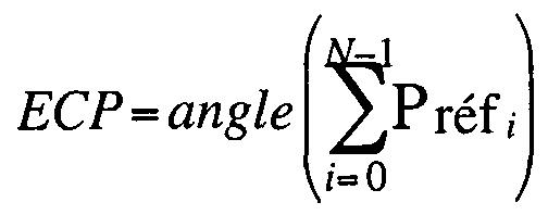
  • the phase of this vector corresponds to the common phase error "ECP” and the amplitude of this vector to the common amplitude error "ECA”, both expressed by means of the following mathematical formulas and illustrated in FIG. 6
  • the common “ECP” phase error 69 is expressed:
  • o P refj is the complex residual error on the reference pilots i, where i is the index (from 0 to N- 1) of the N reference pilots taken into account; o N: is the variable defining the number of pilots in the calculation.
  • H is the first estimate of the response of the channel before correction
  • the weighting of this first estimate of channel with the global error vector makes it possible to obtain a new more precise estimate of channel noted H 2 which holds account for phase errors of the receiver oscillators.
  • This second more precise estimate also takes into account the channel variations which could not usually be measured with the techniques of the prior art and which are partly at the origin of the improvement of the channel estimation applied to demodulation. OFDM.
  • step 1 a Fast Fourier Transformation 510 is applied to the received signal brought back to baseband to identify the set x (n) 511 of the cells associated with each of the OFDM symbols;
  • step 2 a demultiplexing 512 of the cells 511 then makes it possible to dissociate on the one hand the reference pilots 513, and on the other hand the data carriers 514;
  • step 3 a time / frequency interpolation 515 is performed on all of the reference pilots 513, so as to obtain a first estimate h, (n) of the response of the channel 516 before correction;
  • step 4 the calculations 517 of the common phase errors (ECP) and of the common amplitude errors (ECA) are then carried out from the reference pilots 513, and from the first estimate h, (n) of the response channel 516 before correction;
  • step 5 calculation of a second more precise estimate h 2 (n) of the response of channel 518 after correction;
  • step 6 calculation of a second more precise estimate h 2 (n) of the response of
  • FIG. 7 illustrates an example of results obtained without application and with application of the algorithm according to the invention, on an experimental broadcast of a DRM signal from a tower at the frequency of 26 MHz with mode A (which has a pilot every twenty cells in frequency and every five cells in time).
  • mode A which has a pilot every twenty cells in frequency and every five cells in time.
  • the uncorrected channel 72 includes bellies and nodes 73 whose recurrence is greater than what the selected OFDM mode allows. Thanks to the technique according to the invention, after correction, the audio service 71 functions perfectly, as illustrated by the reference 74.
  • FIG. 7 also illustrates the signals obtained for: an uncorrected module 75; a corrected module 76; an uncorrected phase 77; a corrected phase 78. 8.
  • the method and device for estimating a propagation channel formed by successive symbols of a multicarrier signal each comprising at least at least one reference pilot, and one plurality of frequencies carrying data, as proposed by the invention have a number of advantages, a non-exhaustive list of which is given below: optimization of the channel estimation in OFDM; correction of data pilots vis-à-vis the propagation channel; - possibility of obtaining the impulse response of the channel, which can be used to refine the time synchronization of the receivers application to OFDM reception in mobility of the type comprising: DRM,

Abstract

The invention relates to a method for estimating a propagation channel composed of successive symbols of a multicarrier signal, each comprising at least one reference pilot (513) and a plurality of data-carrying frequencies. Such a method comprises, in particular, at least one step consisting of correcting the at least one reference pilot (513) on the basis of a first estimation of a propagation channel (516), in order to provide a second, more precise estimation of said channel (516).

Description

Procédé et dispositif d'estimation d'un canal de propagation d'un signal multiporteuse. 1. Domaine de l'invention Le domaine de l'invention est celui des communications numériques appliquées, des systèmes de diffusion numérique hertzienne, du type appartenant au groupe comprenant DAB, DVB-T, DRM, mais également des télécommunications (ADSL, Hyperlan2, etc.). Plus précisément, l'invention concerne les récepteurs du type DAB, DVB-T, DRM qui utilisent la démodulation OFDM (« Orthogonal Frequency Division Multiplex » en anglais, pour « Multiplexage par division orthogonal de fréquence »), laquelle est de plus en plus utilisée dans les domaines précités. 2. L'art antérieur 2.1. Rappel sur le principe de la modulation OFDM La modulation OFDM consiste à répartir dans l'espace temps/fréquence des données de durée Tu (dit temps-symbole utile) sur une pluralité de fréquences porteuses modulées indépendamment, par exemple en QPSK ou QAM. L'OFDM découpe ainsi le canal en cellules selon les axes du temps 11 et des fréquences 12, comme illustré sur la figure 1. Chacune des porteuses est orthogonale à la précédente. Le canal de longueur prédéterminée 13 est alors constitué d'une suite de sous-bandes de fréquence 14 et d'une suite de segments temporels 15. A chaque cellule fréquence/temps est attribuée une porteuse dédiée. On va donc répartir l'information à transporter sur l'ensemble de ces porteuses, modulée chacune à faible débit par exemple, par une modulation du type QPSK ou QAM. Un symbole OFDM comprend l'ensemble des informations portées par l'ensemble des porteuses à un instant t. Cette technique de modulation est notamment efficace dans les situations où l'on rencontre des multitrajets. Comme illustré sur la figure 2 qui présente un ensemble de symboles OFDM 21 , une même suite de symboles arrivant à un récepteur par deux chemins différents se présente comme la même information arrivant à deux instants différents et qui s'additionnent. Ces échos provoquent deux types de défauts : l'interférence intra symbole : addition d'un symbole avec lui-même légèrement déphasé ; - l'interférence inter symbole : addition d'un symbole avec le suivant plus le précédent légèrement déphasé. Entre chaque symbole transmis, on insère une zone « morte » appelée intervalle de garde 22, dont la durée 23 est choisie suffisamment grande par rapport à l'étalement des échos. Ces précautions vont limiter l'interférence inter symbole (celle ci étant absorbée par l'intervalle de garde). A la réception, les porteuses ont subi en outre soit une atténuation (échos destructifs), soit une amplification (échos constructifs) et/ou une rotation de phase. Pour calculer la fonction transfert du canal et ainsi effectuer une égalisation du signal avant démodulation, on insère des porteuses pilotes de synchronisation (d'amplitude souvent supérieure aux porteuses de données utiles). La valeur et l'emplacement de ces pilotes dans l'espace temps/fréquence sont prédéfinis et connus des récepteurs. Après une interpolation en temps et en fréquences, on obtient une estimation de la réponse du canal plus ou moins pertinente en fonction du nombre de pilotes de référence et de leur répartition dans le domaine temps/fréquence. 2.2. Application dans les bandes AM (DRM) La modulation OFDM est de plus en plus utilisée dans la diffusion numérique car elle très bien adaptée aux variations du canal radio : les échos, le doppler. Les ingénieurs, pour choisir la structure OFDM la mieux adaptée, étudient d'abord les caractéristiques du canal radio qui varient en fonction de la fréquence d'émission, de la bande passante du signal mais aussi, pour la radio numérique dans les bandes AM (DRM), des conditions de propagations entre le jour et la nuit et des cycles solaires. Les récepteurs utilisés pour la démodulation OFDM exploitent essentiellement la réponse du canal calculée à partir des pilotes de référence. La justesse de cette estimation dépend donc de la proportion de pilotes de référence insérés dans les symboles OFDM. 2.3. Inconvénients des techniques de l'art antérieur Un algorithme de correction de l'erreur de phase commune est connu, mais l'erreur traitée correspond à l'erreur relative entre deux symboles OFDM successifs, l'objectif étant alors de corriger les erreurs de phase dues aux défauts des oscillateurs utilisés dans les récepteurs. Toutefois, notamment pour le DRM, on constate des variations rapides de canal, notamment lorsqu'on se déplace en automobile, qui peuvent conduire à des pertes de services momentanées (partielles ou totales). En particulier, pour corriger les variations de phase entre deux symboles OFDM successifs, les techniques connues s'appuient sur le calcul de l'erreur de phase commune par différentiation entre deux symboles successifs. Cette correction est donc effectuée avant l'estimation de canal. C'est par exemple le cas de la solution proposée par France Télécom et Télédiffusion de France (TDF) dans leur brevet français n° FR 2,768,278. Cependant, cela peut s'avérer insuffisant, notamment dans le cas du DRM. 3. Objectifs de l'invention L'invention a notamment pour objectif de pallier ces inconvénients principaux de l'art antérieur. Plus précisément, un objectif de l'invention est de fournir un procédé et un dispositif permettant d'optimiser l'estimation d'un canal de propagation, notamment d'un canal OFDM, par exemple pour des applications du type DRM. Notamment, un objectif supplémentaire de l'invention est de lutter contre les évanouissements forts que l'on peut rencontrer, par exemple dans le cas du DRM. Un autre objectif de l'invention est de fournir un procédé et un dispositif permettant de corriger les pilotes de référence en fonction d'un canal de propagation correspondant. Un objectif supplémentaire de l'invention est de fournir un procédé et un dispositif d'estimation permettant d'affiner la synchronisation des récepteurs. Encore un objectif de l'invention est de fournir un procédé et un dispositif qui soient faciles à mettre en œuvre, tout en restant de coût raisonnable. Un dernier objectif de l'invention est de fournir un procédé et un dispositif qui corrige également le problème de l'erreur de phase commune sur un signal OFDM en réception, induit par exemple par les bruits de phases des oscillateurs, en complément de l'erreur commune aux symboles OFDM sur l'amplitude. 4. Caractéristiques principales de l'invention Ces objectifs, ainsi que d'autres qui apparaîtront par la suite sont atteints à l'aide d'un procédé d'estimation d'un canal de propagation formé de symboles successifs d'un signal multiporteuse comprenant chacun au moins au moins un pilote de référence, et une pluralité de fréquences portant des données. Un tel procédé comprend avantageusement au moins une étape de correction du ou des pilotes de référence, en fonction d'une première estimation d'un canal de propagation, de façon à délivrer une seconde estimation du canal, plus précise. Cette approche repose notamment sur l'observation, faite par les inventeurs, que les algorithmes actuellement connus parmi les solutions de l'art antérieur n'utilisent pas toutes les informations qu'il est possible d'extraire des pilotes de référence. L'article intitulé « The effect of phase noise in COFDM » ou « l'effet du bruit de phase en COFDM » publié en 1998 dans la revue « EBU Technical Review » par J. Scott identifie le problème de l'erreur de phase commune sur un signal OFDM en réception, induit par exemple par les bruits de phases des oscillateurs. Cet article de l'art antérieur ne propose cependant aucune correction à ce problème. Avantageusement, cette première étape d'estimation d'un canal de propagation tient compte des pilotes reçus avant qu'ils ne soient corrigés. De façon préférentielle, l'étape de correction comprend une étape de calcul d'un vecteur d'erreur d'amplitude et/ou de phase, pour chacun des pilotes de référence. Préférentiellement, l'étape de calcul d'un vecteur d'erreur met en œuvre un moyennage d'un ensemble de vecteurs d'erreurs obtenus sur au moins un symbole. Ce moyennage peut correspondre par exemple à une intégration sur les vecteurs d'erreurs obtenus pour chacun des symboles, de façon à éliminer tout risque d'introduction de bruit que pourrait engendrer une prise en compte de pilotes atypiques. De façon avantageuse, le moyennage est calculé sur chaque symbole. Avantageusement, l'ensemble de vecteurs d'erreur ne comprend que les vecteurs d'erreur répondant à au moins un critère prédéterminé de qualité. De façon préférentielle, l'étape de calcul d'un vecteur d'erreur d'amplitude et/ou de phase comprend une étape préliminaire de rejet, pour ce calcul, des pilotes dont l'amplitude est inférieure à un premier seuil moyen minimum prédéterminé et/ou supérieure à un deuxième seuil moyen maximum prédéterminé, de façon à éviter tout risque d'introduction de biais dans le calcul du vecteur d'erreur d'amplitude et/ou de phase. En effet, à titre de simple exemple illustratif, il est fréquent lors de l'estimation classique d'un canal d'obtenir une erreur en amplitude et une erreur en phase qui soient suffisamment importantes en pourcentage pour rendre ainsi ce dernier inexploitable.Method and device for estimating a propagation channel of a multicarrier signal. 1. Field of the invention The field of the invention is that of applied digital communications, over-the-air digital broadcasting systems, of the type belonging to the group comprising DAB, DVB-T, DRM, but also telecommunications (ADSL, Hyperlan2, etc.). More specifically, the invention relates to receivers of the DAB, DVB-T, DRM type which use OFDM demodulation (“Orthogonal Frequency Division Multiplex” in English, for “Multiplexing by orthogonal frequency division”), which is more and more used in the aforementioned fields. 2. The prior art 2.1. Recall on the principle of OFDM modulation OFDM modulation consists in distributing in time / frequency space data of duration Tu (said useful symbol time) over a plurality of carrier frequencies modulated independently, for example in QPSK or QAM. The OFDM thus cuts the channel into cells along the axes of time 11 and frequencies 12, as illustrated in FIG. 1. Each of the carriers is orthogonal to the previous one. The channel of predetermined length 13 then consists of a series of frequency sub-bands 14 and a series of time segments 15. Each frequency / time cell is assigned a dedicated carrier. We will therefore distribute the information to be transported over all of these carriers, each modulated at low speed for example, by QPSK or QAM type modulation. An OFDM symbol includes all of the information carried by all of the carriers at an instant t. This modulation technique is particularly effective in situations where multi-paths are encountered. As illustrated in FIG. 2 which presents a set of OFDM symbols 21, the same series of symbols arriving at a receiver by two different paths is presented as the same information arriving at two different moments and which add up. These echoes cause two types of defects: intra-symbol interference: addition of a symbol with itself slightly out of phase; - inter-symbol interference: addition of a symbol with the next plus the slightly out-of-step previous. Between each transmitted symbol, a “dead” zone called the guard interval 22 is inserted, the duration 23 of which is chosen to be sufficiently large in relation to the spread of the echoes. These precautions will limit inter symbol interference (this being absorbed by the guard interval). On reception, the carriers have also undergone either attenuation (destructive echoes), or amplification (constructive echoes) and / or phase rotation. To calculate the channel transfer function and thus perform an equalization of the signal before demodulation, pilot synchronization carriers (of amplitude often greater than the payload carriers) are inserted. The value and location of these pilots in time / frequency space are predefined and known to the receivers. After an interpolation in time and frequencies, one obtains an estimate of the response of the channel more or less relevant according to the number of reference pilots and their distribution in the time / frequency domain. 2.2. Application in AM bands (DRM) OFDM modulation is used more and more in digital broadcasting because it is very well adapted to variations in the radio channel: echoes, doppler. The engineers, to choose the most suitable OFDM structure, first study the characteristics of the radio channel which vary according to the transmission frequency, the signal bandwidth but also, for digital radio in the AM bands ( DRM), day-to-night propagation conditions and solar cycles. The receivers used for OFDM demodulation essentially use the channel response calculated from the reference pilots. The the accuracy of this estimate therefore depends on the proportion of reference pilots inserted in the OFDM symbols. 2.3. Disadvantages of the techniques of the prior art A common phase error correction algorithm is known, but the error processed corresponds to the relative error between two successive OFDM symbols, the objective then being to correct the phase errors due to faults in the oscillators used in the receivers. However, especially for DRM, there are rapid variations in channel, especially when traveling by car, which can lead to temporary loss of service (partial or total). In particular, to correct the phase variations between two successive OFDM symbols, the known techniques rely on the calculation of the common phase error by differentiation between two successive symbols. This correction is therefore made before the channel estimation. This is for example the case of the solution proposed by France Télécom et Télédiffusion de France (TDF) in their French patent n ° FR 2,768,278. However, this may prove to be insufficient, especially in the case of DRM. 3. Objectives of the invention The object of the invention is in particular to overcome these main drawbacks of the prior art. More specifically, an objective of the invention is to provide a method and a device making it possible to optimize the estimation of a propagation channel, in particular of an OFDM channel, for example for applications of the DRM type. In particular, an additional objective of the invention is to combat the strong fainting that can be encountered, for example in the case of DRM. Another objective of the invention is to provide a method and a device making it possible to correct the reference pilots as a function of a corresponding propagation channel. An additional objective of the invention is to provide an estimation method and device making it possible to refine the synchronization of the receivers. Another objective of the invention is to provide a method and a device which are easy to implement, while remaining of reasonable cost. A final objective of the invention is to provide a method and a device which also corrects the problem of the common phase error on an OFDM signal on reception, induced for example by the phase noises of the oscillators, in addition to the error common to OFDM symbols on amplitude. 4. MAIN CHARACTERISTICS OF THE INVENTION These objectives, as well as others which will appear subsequently, are achieved using a method for estimating a propagation channel formed by successive symbols of a multicarrier signal comprising each at least at least one reference pilot, and a plurality of frequencies carrying data. Such a method advantageously comprises at least one step of correcting the reference pilot or pilots, as a function of a first estimate of a propagation channel, so as to deliver a second, more precise estimate of the channel. This approach is based in particular on the observation made by the inventors that the algorithms currently known among the solutions of the prior art do not use all the information that it is possible to extract from reference pilots. The article entitled "The effect of phase noise in COFDM" or "the effect of phase noise in COFDM" published in 1998 in the review "EBU Technical Review" by J. Scott identifies the problem of common phase error on an OFDM signal on reception, induced for example by the phase noises of the oscillators. This article of the prior art does not, however, propose any correction to this problem. Advantageously, this first step of estimating a propagation channel takes account of the pilots received before they are corrected. Preferably, the correction step comprises a step of calculating an amplitude and / or phase error vector, for each of the reference pilots. Preferably, the step of calculating an error vector implements an averaging of a set of error vectors obtained on at least one symbol. This averaging can correspond, for example, to an integration on the error vectors obtained for each of the symbols, so as to eliminate any risk of noise introduction that could be caused by taking into account atypical pilots. Advantageously, the averaging is calculated on each symbol. Advantageously, the set of error vectors comprises only the error vectors meeting at least one predetermined quality criterion. Preferably, the step of calculating an amplitude and / or phase error vector comprises a preliminary step of rejecting, for this calculation, pilots whose amplitude is less than a first predetermined minimum average threshold. and / or greater than a second predetermined maximum average threshold, so as to avoid any risk of introducing bias in the calculation of the amplitude and / or phase error vector. Indeed, as a simple illustrative example, it is common during the conventional estimation of a channel to obtain an amplitude error and a phase error which are sufficiently large in percentage to thus make the latter unusable.
Au contraire, le procédé selon l'invention permet de démoduler tous les pilotes pour en extraire une estimation commune applicable au canal, en appliquant l'estimation du canal sur les données elles-mêmes.On the contrary, the method according to the invention makes it possible to demodulate all the pilots in order to extract therefrom a common estimate applicable to the channel, by applying the estimation of the channel to the data themselves.
Ainsi, plus le nombre de ces pilotes est important pour un même symbole et meilleur sera l'estimation des erreurs et le bruit blanc additif gaussien sera minimal. Les pilotes dont l'amplitude est très faible par rapport à la moyenne sur un symbole ou trop importante (pouvant être considérée comme un parasite) ne sont pas pris en compte dans l'opération. Avantageusement, la seconde estimation comprend une étape d'égalisation, en fonction de la première estimation du canal. De façon avantageuse, l'étape d'égalisation est effectuée sur l'ensemble des fréquences porteuses de chacun des symboles. Da façon également avantageuse, l'étape d'égalisation est suivie d'une étape de calcul d'une réponse impulsionnelle d'un canal de propagation, en fonction des pilotes de référence égalisés pour l'affinage d'une synchronisation temporelle des récepteurs. Préférentiellement, l'étape de correction des pilotes de référence comprend une division de ces pilotes par la première estimation du canal de propagation. De façon préférentielle, l'étape de correction des pilotes de référence comprend en outre une dernière étape de correction de toutes les porteuses utiles égalisées tenant compte de la valeur moyenne obtenue en résultat du moyennage. Le procédé selon l'invention est utilisé de façon avantageuse pour la correction d'au moins une erreur de phase et/ou d'amplitude commune à deux cellules d'un même symbole du type OFDM («Orthogonal Frequency DivisionThus, the greater the number of these pilots for the same symbol, the better the estimation of the errors and the additive Gaussian white noise will be minimal. Pilots whose amplitude is very low compared to the average on a symbol or too large (which can be considered as a parasite) are not taken into account in the operation. Advantageously, the second estimate includes an equalization step, as a function of the first estimate of the channel. Advantageously, the equalization step is carried out on all of the carrier frequencies of each of the symbols. Da also advantageously, the equalization step is followed by a step of calculating an impulse response of a propagation channel, depending on the equalized reference pilots for refining time synchronization of receivers. Preferably, the step of correcting the reference pilots comprises a division of these pilots by the first estimation of the propagation channel. Preferably, the step of correcting the reference pilots further comprises a final step of correcting all the equalized useful carriers taking into account the average value obtained as a result of the averaging. The method according to the invention is advantageously used for the correction of at least one phase and / or amplitude error common to two cells of the same symbol of the OFDM (“Orthogonal Frequency Division”) type.
Multiplex» en anglais, pour « Multiplexage par division orthogonal de fréquence»). L'invention concerne également un dispositif d'estimation d'un canal de propagation formé de symboles successifs d'un signal multiporteuses comprenant chacun au moins au moins un pilote de référence, et une pluralité de fréquences portant des données. Un tel dispositif comprend ainsi, de façon préférentielle, des moyens de correction du ou des pilotes de référence, en fonction d'une première estimation d'un canal de propagation, de façon à délivrer une seconde estimation du canal, plus précise. 5. Liste des figures D'autres caractéristiques et avantages de l'invention apparaîtront plus clairement à la lecture de la description suivante d'un mode de réalisation préférentiel, donné à titre de simple exemple illustratif et non limitatif, et des dessins annexés, parmi lesquels : - la figure 1 précédemment décrite en préambule, est une représentation temps/fréquence d'un canal OFDM découpé en cellules, le canal étant alors constitué d'une suite de sous-bandes de fréquence et d'une suite de segments temporels ; - la figure 2, également décrite ci-avant, présente un ensemble de symboles OFDM ; - la figure 3 illustre un exemple de structure OFDM en mode A d'un ensemble de symboles DRM ; - la figure 4 illustre un deuxième exemple de structure OFDM, mais pour un ensemble de symboles DVB-T ; - la figure 5 est une description schématisée de l'algorithme fonctionnel du procédé selon l'invention. Elle est détaillée ci-après. - la figure 6 donne un exemple de la détermination d'un vecteur d'erreur global à partir de sept vecteurs d'erreur respectivement obtenus pour N= 7 pilotes. Elle est détaillée ci-après. - la figure 7 donne un exemple de résultats obtenus sans application et avec application de l'algorithme selon l'invention, sur une diffusion expérimentale d'un signal DRM depuis une tour à la fréquence de 26 MHz avec le mode A. Elle met en évidence l'erreur résiduelle de l'estimation de canal avant et après application des corrections d'erreur commune. Elle est détaillée au paragraphe 7.2 de description d'un mode de réalisation préférentielle de l'invention. 7. Rappel du principe général de l'invention L'invention vise donc à permettre la correction d'une ou plusieurs erreurs de phase et/ou d'amplitude commune aux cellules comprises dans un même symbole OFDM, de façon à optimiser l'estimation d'un canal OFDM. De façon plus détaillée, dans le signal OFDM, des pilotes dits de référence sont en effet intégrés pour estimer le canal de propagation. Cette estimation permet d'une part de corriger les pilotes dits de données vis-à-vis du canal de propagation, et d'autre part d'obtenir la réponse impulsionnelle du canal, cette dernière étant alors utilisée pour affiner la synchronisation temporelle des récepteurs. A titre informatif, l'utilisation des pilotes de références dans les systèmes de radiodiffusion sonore numérique, notamment du type COFDM (« CodingMultiplex "in English, for" Multiplexing by orthogonal frequency division "). The invention also relates to a device for estimating a propagation channel formed of successive symbols of a multicarrier signal each comprising at least at least one reference pilot, and a plurality of frequencies carrying data. Such a device thus preferably comprises means for correcting the reference pilot or pilots, as a function of a first estimate of a propagation channel, so as to deliver a second, more precise estimate of the channel. 5. List of Figures Other characteristics and advantages of the invention will appear more clearly on reading the following description of a preferred embodiment, given by way of simple illustrative and nonlimiting example, and of the appended drawings, among which: FIG. 1, previously described in the preamble, is a time / frequency representation of an OFDM channel divided into cells, the channel then consisting of a series of frequency sub-bands and a series of time segments; - Figure 2, also described above, shows a set of OFDM symbols; - Figure 3 illustrates an example of OFDM structure in mode A of a set of DRM symbols; - Figure 4 illustrates a second example of OFDM structure, but for a set of DVB-T symbols; - Figure 5 is a schematic description of the functional algorithm of the method according to the invention. It is detailed below. - Figure 6 gives an example of the determination of a global error vector from seven error vectors respectively obtained for N = 7 pilots. It is detailed below. - Figure 7 gives an example of results obtained without application and with application of the algorithm according to the invention, on an experimental broadcast of a DRM signal from a tower at the frequency of 26 MHz with mode A. It sets evidence of the residual error of the channel estimate before and after application of the common error corrections. It is detailed in paragraph 7.2 of description of a preferred embodiment of the invention. 7. Reminder of the general principle of the invention The invention therefore aims to allow the correction of one or more phase and / or amplitude errors common to the cells included in the same OFDM symbol, so as to optimize the estimation. an OFDM channel. In more detail, in the OFDM signal, so-called reference pilots are in fact integrated to estimate the propagation channel. This estimation makes it possible on the one hand to correct the so-called data pilots with respect to the propagation channel, and on the other hand to obtain the impulse response of the channel, the latter then being used to refine the time synchronization of the receivers . For information, the use of reference pilots in digital sound broadcasting systems, in particular of the COFDM type ("Coding
Orthogonal Frequency Division Multiplex » en anglais, pour « Multiplexage de Fréquences Orthogonales Codées » en français) est décrite dans le brevet français n° FR 2,658,016 du 6 février 1990 concernant un « procédé de diffusion de données numériques, notamment pour la radiodiffusion à haut débit vers des mobiles, à entrelacement temps-fréquence et démodulation cohérente, et récepteur correspondant. Un tel procédé permet notamment de déterminer, par interpolation, une référence de phase et d'amplitude pour chacun des éléments numériques, et ainsi de réaliser une démodulation cohérente. 7. Description d'un mode de réalisation préférentiel de l'invention Il est donc possible avec le procédé selon l'invention de déterminer la rotation de phase d'un symbole OFDM après correction de canal. Une telle technique permet de compenser les variations de phases issues des oscillateurs des récepteurs, mais il est également possible de déterminer les variations d'amplitude commune à un symbole. Ces deux informations permettent de suivre les variations du canal au rythme des symboles dans le domaine temporel. Dans un mode de réalisation préférentiel de l'invention, il s'agit de corriger une erreur de phase et d'amplitude commune aux cellules comprises dans un même symbole OFDM. Cette technique permet de suivre des variations de canal au rythme des symboles OFDM, ce qui est supérieur à ce que permet l'estimation de canal classique du fait de la répartition en temps et en fréquence des pilotes de référence qui sont souvent en nombre limité pour ne pas trop diminuer le débit utile. Une fois les synchronisations temporelle et fréquentielle « grossières » établies, par corrélation des intervalles de garde, par exemple, il est possible d'obtenir la réponse du canal par interpolation sur les pilotes de références. Une fois cette estimation obtenue, une égalisation est appliquée à tous les pilotes de référence ou de données des symboles OFDM. Au niveau des pilotes de références, après égalisation, il devient alors possible de déterminer une erreur résiduelle, entre les pilotes émis et les pilotes reçus ? Celle-ci provient en général d'un bruit blanc additif gaussien ou encore, d'une erreur liée aux limites de l'interpolation temporelle et fréquentielle, c'est-à-dire, de l'estimation de canal. En intégrant l'ensemble des vecteurs sur un symbole, ce qui revient à les moyenner, on obtient un vecteur d'erreur globale. Une confiance des vecteurs élémentaires est obtenue à partir de l'estimation de canal, cette opération permettant le rejet des faibles signaux (noyés dans le bruit) ou des pics parasites. La phase de ce vecteur correspond à l'erreur commune de phase « ECP » et l'amplitude de ce vecteur à l'erreur commune d'amplitude « ECA », toutes deux exprimées au moyen des formules mathématiques suivantes et illustrées sur la figure 6. Cette figure 6 donne un exemple illustratif de la détermination d'un vecteur d'erreur global 61, à partir de sept vecteurs d'erreur (62, 63, 64, 65, 66, 67, 68) respectivement obtenus pour N= 7 pilotes. L'erreur commune de phase « ECP » 69 s'exprime :Orthogonal Frequency Division Multiplex "in English, for" Multiplexing of Orthogonal Coded Frequencies "in French) is described in French patent n ° FR 2,658,016 of February 6, 1990 concerning a" process of diffusion of digital data, in particular for broadband broadcasting to mobiles, with time-frequency interleaving and coherent demodulation, and corresponding receiver. Such a method makes it possible in particular to determine, by interpolation, a phase and amplitude reference for each of the digital elements, and thus to carry out a coherent demodulation. 7. Description of a preferred embodiment of the invention It is therefore possible with the method according to the invention to determine the phase rotation of an OFDM symbol after channel correction. Such a technique makes it possible to compensate for the variations in phases originating from the oscillators of the receivers, but it is also possible to determine the variations in amplitude common to a symbol. These two pieces of information make it possible to follow the variations of the channel at the rate of the symbols in the time domain. In a preferred embodiment of the invention, it is a question of correcting a phase and amplitude error common to the cells included in the same OFDM symbol. This technique makes it possible to follow channel variations at the rate of the OFDM symbols, which is greater than what the conventional channel estimation allows because of the time and frequency distribution of the reference pilots which are often in limited number for do not reduce the useful flow too much. Once the “rough” time and frequency synchronizations have been established, by correlation of the guard intervals, for example, it is possible to obtain the response of the channel by interpolation on the reference pilots. Once this estimate is obtained, an equalization is applied to all the reference or data pilots of the OFDM symbols. At the level of the reference pilots, after equalization, it then becomes possible to determine a residual error, between the emitted pilots and the received pilots? This generally comes from an additive white Gaussian noise or from an error linked to the limits of the temporal and frequency interpolation, that is to say, of the channel estimation. By integrating all the vectors on a symbol, which amounts to averaging them, we obtain a global error vector. Vector confidence elementary is obtained from the channel estimation, this operation allowing the rejection of weak signals (drowned in noise) or parasitic peaks. The phase of this vector corresponds to the common phase error "ECP" and the amplitude of this vector to the common amplitude error "ECA", both expressed by means of the following mathematical formulas and illustrated in FIG. 6 This figure 6 gives an illustrative example of the determination of a global error vector 61, from seven error vectors (62, 63, 64, 65, 66, 67, 68) respectively obtained for N = 7 drivers. The common “ECP” phase error 69 is expressed:
Figure imgf000011_0001
et l'erreur commune d'amplitude « ECA » 61 :
Figure imgf000011_0001
and the common amplitude error "ECA" 61:
Figure imgf000011_0002
ou o P réfj : est l'erreur résiduelle complexe sur les pilotes de référence i, où i est l'indice (de 0 à N- 1 ) des N pilotes de références pris en compte ; o N : est la variable définissant le nombre de pilotes dans le calcul. De façon complémentaire, si H, est la première estimation de la réponse du canal avant correction, la pondération de cette première estimation de canal avec le vecteur d'erreur global permet d'obtenir une nouvelle estimation plus précise de canal notée H2 qui tient compte des erreurs de phase des oscillateurs des récepteurs. Cette deuxième estimation plus précise tient compte également des variations de canal qui ne pouvaient habituellement pas être mesurées avec les techniques de l'art antérieur et qui sont en partie à l'origine de l'amélioration de l'estimation de canal appliquée à la démodulation OFDM. Cette deuxième estimation de canal plus précise s'exprime au moyen de la formule mathématique suivante : hin>= ECA où h,(n) : est la réponse du canal avant correction. Il devient alors possible d'évaluer la valeur d'estimation affinée attribuée à l'ensemble des cellules égalisées par l'estimation par la formule mathématique suivante :
Figure imgf000012_0001
où : o y(n) : est l'ensemble des cellules égalisées par l'estimation ; o h2(n) : est la réponse du canal après correction par l'ECP et l'ECA; o x(n) : est l'ensemble des cellules associées à un symbole OFDM. La figure 5 est une description schématisée de l'algorithme fonctionnel décrit ci-dessus et pour lequel nous rappelons les étapes principales : - étape 1 : une transformée de Fourier Rapide (« Fast Fourier Transformation » en anglais) 510 est appliquée sur le signal reçu ramené en bande de base pour identifier l'ensemble x(n) 511 des cellules associées à chacun des symboles OFDM ; - étape 2 : un démultiplexage 512 des cellules 511 permet ensuite de dissocier d'une part les pilotes de référence 513, et d'autre part les porteuses de données 514 ; - étape 3 : un interpolation temps/fréquence 515 est effectuée sur l'ensemble des pilotes de références 513, de façon à obtenir une première estimation h,(n) de la réponse du canal 516 avant correction ; - étape 4 : les calculs 517 des erreurs communes de phase (ECP) et d'erreurs communes d'amplitude (ECA) sont ensuite réalisés à partir des pilotes de référence 513, et de la première estimation h,(n) de la réponse du canal 516 avant correction ; - étape 5 : calcul d'une deuxième estimation plus précise h2(n) de la réponse du canal 518 après correction ; - étape 6 : égalisation 519 l'ensemble des cellules 512 à partir de l'ensemble des porteuses de données 514 et du résultat de la deuxième estimation 518, de façon à définir l'ensemble 520 des cellules égalisées y(n) par l'estimation ; étape 7 : application du traitement des données 521 et calcul 522 de l'erreur résiduelle complexe sur les pilotes de référence i corrigés, de façon à effectuer un dernier réglage temporel 523 sur les pilotes corrigés. La figure 7 illustre un exemple de résultats obtenus sans application et avec application de l'algorithme selon l'invention, sur une diffusion expérimentale d'un signal DRM depuis une tour à la fréquence de 26 MHz avec le mode A (qui possède un pilote de référence toutes les vingt cellules en fréquence et toutes les cinq cellules en temps). Lorsque l'on se déplace à proximité de la tour à 50km/h le service audio 71 est très perturbé : le canal non corrigé 72 comporte des ventres et des nœuds 73 dont la récurrence est supérieure à ce que permet le mode OFDM retenu. Grâce à la technique selon l'invention, après correction, le service audio 71 fonctionne parfaitement, comme illustré par la référence 74. La figure 7 illustre également les signaux obtenus pour : un module non corrigé 75 ; un module corrigé 76 ; une phase non corrigée 77 ; une phase corrigée 78. 8. Avantages de la solution selon l'invention Les procédé et dispositif d'estimation d'un canal de propagation formé de symboles successifs d'un signal multiporteuse comprenant chacun au moins au moins un pilote de référence, et une pluralité de fréquences portant des données, tels que proposés par l'invention présentent un certain nombre d'avantages, dont une liste non exhaustive est donnée ci-dessous : optimisation de l'estimation de canal en OFDM ; correction des pilotes de données vis-à-vis du canal de propagation ; - possibilité d'obtenir la réponse impulsionnelle du canal, cette dernière pouvant être utilisée pour affiner la synchronisation temporelle des récepteurs application à la réception OFDM en mobilité du type comprenant : DRM,
Figure imgf000011_0002
or o P refj: is the complex residual error on the reference pilots i, where i is the index (from 0 to N- 1) of the N reference pilots taken into account; o N: is the variable defining the number of pilots in the calculation. In a complementary way, if H, is the first estimate of the response of the channel before correction, the weighting of this first estimate of channel with the global error vector makes it possible to obtain a new more precise estimate of channel noted H 2 which holds account for phase errors of the receiver oscillators. This second more precise estimate also takes into account the channel variations which could not usually be measured with the techniques of the prior art and which are partly at the origin of the improvement of the channel estimation applied to demodulation. OFDM. This second more precise channel estimate is expressed by the following mathematical formula: h i n > = ECA where h, (n): is the response of the channel before correction. It then becomes possible to evaluate the refined estimate value assigned to the set of equalized cells by the estimate by the following mathematical formula:
Figure imgf000012_0001
where: oy (n): is the set of cells equalized by the estimate; oh 2 (n): is the response of the channel after correction by the ECP and the ECA; ox (n): is the set of cells associated with an OFDM symbol. FIG. 5 is a schematic description of the functional algorithm described above and for which we recall the main steps: - step 1: a Fast Fourier Transformation 510 is applied to the received signal brought back to baseband to identify the set x (n) 511 of the cells associated with each of the OFDM symbols; step 2: a demultiplexing 512 of the cells 511 then makes it possible to dissociate on the one hand the reference pilots 513, and on the other hand the data carriers 514; step 3: a time / frequency interpolation 515 is performed on all of the reference pilots 513, so as to obtain a first estimate h, (n) of the response of the channel 516 before correction; step 4: the calculations 517 of the common phase errors (ECP) and of the common amplitude errors (ECA) are then carried out from the reference pilots 513, and from the first estimate h, (n) of the response channel 516 before correction; step 5: calculation of a second more precise estimate h 2 (n) of the response of channel 518 after correction; step 6: equalization 519 the set of cells 512 from the set of data carriers 514 and the result of the second estimate 518, so as to define the set 520 of equalized cells y (n) by the estimation; step 7: application of the data processing 521 and calculation 522 of the complex residual error on the corrected reference pilots i, so as to carry out a last time adjustment 523 on the corrected pilots. FIG. 7 illustrates an example of results obtained without application and with application of the algorithm according to the invention, on an experimental broadcast of a DRM signal from a tower at the frequency of 26 MHz with mode A (which has a pilot every twenty cells in frequency and every five cells in time). When one moves close to the tower at 50km / h the audio service 71 is very disturbed: the uncorrected channel 72 includes bellies and nodes 73 whose recurrence is greater than what the selected OFDM mode allows. Thanks to the technique according to the invention, after correction, the audio service 71 functions perfectly, as illustrated by the reference 74. FIG. 7 also illustrates the signals obtained for: an uncorrected module 75; a corrected module 76; an uncorrected phase 77; a corrected phase 78. 8. Advantages of the solution according to the invention The method and device for estimating a propagation channel formed by successive symbols of a multicarrier signal each comprising at least at least one reference pilot, and one plurality of frequencies carrying data, as proposed by the invention have a number of advantages, a non-exhaustive list of which is given below: optimization of the channel estimation in OFDM; correction of data pilots vis-à-vis the propagation channel; - possibility of obtaining the impulse response of the channel, which can be used to refine the time synchronization of the receivers application to OFDM reception in mobility of the type comprising: DRM,
DVB-T, etc.; simplicité de mise en œuvre ; qualité et pertinence des résultats obtenus en termes de correction ; rapidité de la solution et de l'algorithme. DVB-T, etc .; simplicity of implementation; quality and relevance of the results obtained in terms of correction; speed of the solution and the algorithm.

Claims

REVENDICATIONS
1. Procédé d'estimation d'un canal de propagation formé de symboles successifs d'un signal multiporteuse comprenant chacun au moins au moins un pilote de référence, et une pluralité de fréquences portant des données, caractérisé en ce qu'il comprend au moins une étape de correction du ou desdits pilotes de référence, en fonction d'une première estimation d'un canal de propagation, de façon à délivrer une seconde estimation dudit canal, plus précise.1. Method for estimating a propagation channel formed by successive symbols of a multicarrier signal each comprising at least at least one reference pilot, and a plurality of frequencies carrying data, characterized in that it comprises at least a step of correcting said reference pilot or pilots, as a function of a first estimate of a propagation channel, so as to deliver a second estimate of said channel, which is more precise.
2. Procédé d'estimation d'un canal de propagation selon la revendication 1 , caractérisé en ce que ladite première étape d'estimation d'un canal de propagation tient compte des pilotes reçus avant qu'ils ne soient corrigés.2. Method for estimating a propagation channel according to claim 1, characterized in that said first step of estimating a propagation channel takes account of the pilots received before they are corrected.
3. Procédé d'estimation d'un canal de propagation selon l'une quelconque des revendications 1 et 2, caractérisé en ce que ladite étape de correction comprend une étape de calcul d'un vecteur d'erreur d'amplitude et/ou de phase, pour chacun desdits pilotes de référence. 3. Method for estimating a propagation channel according to any one of claims 1 and 2, characterized in that said correction step comprises a step of calculating an amplitude error vector and / or of phase, for each of said reference pilots.
4. Procédé d'estimation d'un canal de propagation selon la revendication 3, caractérisé en ce que ladite étape de calcul d'un vecteur d'erreur met en œuvre un moyennage d'un ensemble de vecteurs d'erreurs obtenus sur au moins un symbole.4. Method for estimating a propagation channel according to claim 3, characterized in that said step of calculating an error vector implements an averaging of a set of error vectors obtained on at least a symbol.
5. Procédé d'estimation d'un canal de propagation selon la revendication 4, caractérisé en ce que ledit moyennage est calculé sur chaque symbole.5. Method for estimating a propagation channel according to claim 4, characterized in that said averaging is calculated on each symbol.
6. Procédé d'estimation d'un canal de propagation selon l'une quelconque des revendications 4 et 5, caractérisé en ce que ledit ensemble de vecteurs d'erreur ne comprend que les vecteurs d'erreur répondant à au moins un critère prédéterminé de qualité. 6. Method for estimating a propagation channel according to any one of claims 4 and 5, characterized in that said set of error vectors comprises only the error vectors meeting at least one predetermined criterion of quality.
7. Procédé d'estimation d'un canal de propagation selon l'une quelconque des revendications 3 à 6, caractérisé en ce que ladite étape de calcul d'un vecteur d'erreur d'amplitude et/ou de phase comprend une étape préliminaire de rejet, pour ce dit calcul, desdits pilotes dont l'amplitude est inférieure à un premier seuil moyen minimum prédéterminé et/ou supérieure à un deuxième seuil moyen maximum prédéterminé, de façon à éviter tout risque d'introduction de biais dans le calcul dudit vecteur d'erreur d'amplitude et/ou de phase. 7. Method for estimating a propagation channel according to any one of claims 3 to 6, characterized in that said step of calculating an amplitude and / or phase error vector comprises a preliminary step rejection, for this said calculation, of said pilots whose amplitude is less than a first predetermined minimum average threshold and / or greater than a second predetermined maximum average threshold, so as to avoid any risk of introducing bias in the calculation of said amplitude and / or phase error vector.
8. Procédé d'estimation d'un canal de propagation selon l'une quelconque des revendications 1 à 7, caractérisé en ce que ladite seconde estimation comprend une étape d'égalisation, en fonction de ladite première estimation du canal.8. Method for estimating a propagation channel according to any one of claims 1 to 7, characterized in that said second estimate comprises an equalization step, as a function of said first estimate of the channel.
9. Procédé d'estimation d'un canal de propagation selon la revendication 8, caractérisé en ce que ladite étape d'égalisation est effectuée sur l'ensemble des fréquences porteuses de chacun desdits symboles.9. A method of estimating a propagation channel according to claim 8, characterized in that said equalization step is performed on all of the carrier frequencies of each of said symbols.
10. Procédé d'estimation d'un canal de propagation selon l'une quelconque des revendications 3 à 9, caractérisé en ce qu'il comprend, après ladite étape d'égalisation, une étape de calcul d'une réponse impulsionnelle d'un canal de propagation, en fonction des pilotes de référence égalisés pour l'affinage d'une synchronisation temporelle des récepteurs.10. Method for estimating a propagation channel according to any one of claims 3 to 9, characterized in that it comprises, after said equalization step, a step of calculating an impulse response of a propagation channel, as a function of the reference pilots equalized for refining a time synchronization of the receivers.
11. Procédé d'estimation d'un canal de propagation selon l'une quelconque des revendications 1 à 10, caractérisé en ce ladite étape de correction des pilotes de référence comprend une division de ces pilotes par la première estimation du canal de propagation.11. Method for estimating a propagation channel according to any one of claims 1 to 10, characterized in that said step of correcting the reference pilots comprises a division of these pilots by the first estimation of the propagation channel.
12. Procédé d'estimation d'un canal de propagation selon l'une quelconque des revendications 1 à 11 , caractérisé en ce que ladite étape de correction des pilotes de référence comprend en outre une dernière étape de correction de toutes les porteuses utiles égalisées tenant compte de la valeur moyenne obtenue en résultat dudit moyennage.12. Method for estimating a propagation channel according to any one of claims 1 to 11, characterized in that said step of correcting the reference pilots further comprises a final step of correcting all the useful carriers equalized holding account for the average value obtained as a result of said averaging.
13. Procédé d'estimation d'un canal de propagation selon l'une quelconque des revendications 1 à 12, caractérisé en ce qu'il est utilisé pour la correction d'au moins une erreur de phase et/ou d'amplitude commune à deux cellules d'un même symbole du type OFDM (« Orthogonal Frequency Division Multiplex » en anglais, pour « Multiplexage par division orthogonal de fréquence »).13. Method for estimating a propagation channel according to any one of claims 1 to 12, characterized in that it is used for the correction of at least one phase error and / or of amplitude common to two cells of the same symbol of the OFDM type (“Orthogonal Frequency Division Multiplex” in English, for “Multiplexing by orthogonal frequency division”).
14. Dispositif d'estimation d'un canal de propagation formé de symboles successifs d'un signal multiporteuses comprenant chacun au moins au moins un pilote de référence, et une pluralité de fréquences portant des données, caractérisé en ce qu'il comprend des moyens de correction du ou desdits pilotes de référence, en fonction d'une première estimation d'un canal de propagation, de façon à délivrer une seconde estimation dudit canal, plus précise. 14. Device for estimating a propagation channel formed by successive symbols of a multicarrier signal each comprising at least at least one reference pilot, and a plurality of frequencies carrying data, characterized in that it comprises means correcting said reference pilot (s), as a function of a first estimate of a propagation channel, so as to deliver a second estimate of said channel, which is more precise.
PCT/FR2004/001900 2003-07-18 2004-07-16 Method and device for estimating a propagation channel of a multicarrier signal WO2005011144A2 (en)

Priority Applications (3)

Application Number Priority Date Filing Date Title
EP04767724.0A EP1661348B1 (en) 2003-07-18 2004-07-16 Method and device for improving the estimation of a propagation channel of a multicarrier signal
US10/564,866 US8094732B2 (en) 2003-07-18 2004-07-16 Method and device for estimating a multicarrier signal propagation channel
CN2004800207656A CN1826785B (en) 2003-07-18 2004-07-16 Method and device for estimating a propagation channel of a multicarrier signal

Applications Claiming Priority (2)

Application Number Priority Date Filing Date Title
FR03/08844 2003-07-18
FR0308844A FR2857802B1 (en) 2003-07-18 2003-07-18 METHOD AND DEVICE FOR ESTIMATING A PROPAGATION CHANNEL OF A MULTI-CARRIER SIGNAL

Publications (2)

Publication Number Publication Date
WO2005011144A2 true WO2005011144A2 (en) 2005-02-03
WO2005011144A3 WO2005011144A3 (en) 2005-05-26

Family

ID=33548280

Family Applications (1)

Application Number Title Priority Date Filing Date
PCT/FR2004/001900 WO2005011144A2 (en) 2003-07-18 2004-07-16 Method and device for estimating a propagation channel of a multicarrier signal

Country Status (5)

Country Link
US (1) US8094732B2 (en)
EP (1) EP1661348B1 (en)
CN (1) CN1826785B (en)
FR (1) FR2857802B1 (en)
WO (1) WO2005011144A2 (en)

Cited By (1)

* Cited by examiner, † Cited by third party
Publication number Priority date Publication date Assignee Title
CN104734840A (en) * 2013-12-19 2015-06-24 想象技术有限公司 Signal Timing

Families Citing this family (16)

* Cited by examiner, † Cited by third party
Publication number Priority date Publication date Assignee Title
US8195627B2 (en) * 2004-04-23 2012-06-05 Neopath Networks, Inc. Storage policy monitoring for a storage network
CN100566317C (en) * 2004-10-22 2009-12-02 财团法人工业技术研究院 Coherent OFDM receiver method for synchronous and device based on frequency dependence
FR2877786B1 (en) * 2004-11-09 2007-03-16 Telediffusion Fse METHOD FOR RECEIVING A MULTI-CARRIER SIGNAL USING AT LEAST TWO ESTIMATES OF A PROPAGATION CHANNEL AND CORRESPONDING RECEIVING DEVICE
EP3457615B1 (en) 2005-08-23 2021-09-22 Apple Inc. Methods and systems for ofdm multiple zone partitioning
EP3174235B1 (en) 2005-08-23 2020-10-21 Apple Inc. Pilot design for ofdm systems with four transmit antennas
WO2007036039A1 (en) 2005-09-30 2007-04-05 Nortel Networks Limited Initial access channel for scalable wireless mobile communication networks
CN101356757B (en) * 2006-01-10 2012-09-05 松下电器产业株式会社 Multicarrier modulation scheme as well as transmission apparatus and reception apparatus using the scheme
JP4802763B2 (en) * 2006-02-28 2011-10-26 カシオ計算機株式会社 OFDM signal receiving apparatus, OFDM signal receiving method, and terrestrial digital broadcast receiving apparatus
US20080101492A1 (en) * 2006-10-31 2008-05-01 Jean-Philippe Gregoire Method for Tracking Phase Noise in an OFDM System
CN101277285A (en) * 2007-03-29 2008-10-01 深圳赛意法微电子有限公司 DRM receiver and demodulation method
WO2008122144A1 (en) * 2007-04-04 2008-10-16 Thomson Licensing Method and apparatus for digital signal reception
CN101803321B (en) * 2007-09-18 2014-04-23 Lg电子株式会社 Method and system for transmitting and receiving signals
WO2009142557A1 (en) * 2008-05-19 2009-11-26 Nanoradio Ab Methods and an apparatus for estimating a residual frequency error in a communications system
CN101771650B (en) * 2009-01-07 2013-08-21 北京泰美世纪科技有限公司 Channel estimation device and method for OFDM system
US9036747B2 (en) * 2011-11-09 2015-05-19 Mediatek Inc. Wireless communication receiver with phase noise estimation and phase noise compensation performed after channel estimation, and related wireless communication receiving method and phase noise compensation apparatus
US20170019191A1 (en) 2015-07-16 2017-01-19 LGS Innovations LLC Self-interference cancellation antenna systems and methods

Citations (2)

* Cited by examiner, † Cited by third party
Publication number Priority date Publication date Assignee Title
EP0762703A1 (en) 1995-08-21 1997-03-12 France Telecom Multicarrier demodulation with reduction of white frequency distortion
FR2768278A1 (en) 1997-09-11 1999-03-12 France Telecom PROCESS FOR ESTIMATING A PARASITIC PHASE OFFSET ON RECEPTION OF A MULTI-PORTABLE SIGNAL, AND CORRESPONDING RECEIVER

Family Cites Families (5)

* Cited by examiner, † Cited by third party
Publication number Priority date Publication date Assignee Title
US6369857B1 (en) * 1999-05-13 2002-04-09 Sarnoff Corporation Receiver for analog and digital television signals
US7020222B2 (en) * 2001-10-24 2006-03-28 Texas Instruments Incorporated Efficient method and system for offset phasor determination
US7180965B2 (en) * 2001-12-12 2007-02-20 Texas Instruments Incorporated Phase estimation and compensation in orthogonal frequency division multiplex (OFDM) systems
US7386217B2 (en) * 2001-12-14 2008-06-10 Hewlett-Packard Development Company, L.P. Indexing video by detecting speech and music in audio
EP1542384A4 (en) * 2002-08-28 2007-06-20 Fujitsu Ltd Transmission/reception apparatus and transmission/reception method

Patent Citations (2)

* Cited by examiner, † Cited by third party
Publication number Priority date Publication date Assignee Title
EP0762703A1 (en) 1995-08-21 1997-03-12 France Telecom Multicarrier demodulation with reduction of white frequency distortion
FR2768278A1 (en) 1997-09-11 1999-03-12 France Telecom PROCESS FOR ESTIMATING A PARASITIC PHASE OFFSET ON RECEPTION OF A MULTI-PORTABLE SIGNAL, AND CORRESPONDING RECEIVER

Cited By (2)

* Cited by examiner, † Cited by third party
Publication number Priority date Publication date Assignee Title
CN104734840A (en) * 2013-12-19 2015-06-24 想象技术有限公司 Signal Timing
CN104734840B (en) * 2013-12-19 2018-08-17 想象技术有限公司 Receiver timing is adjusted to approach the method and its receiver of the signal timing of data-signal

Also Published As

Publication number Publication date
US20070041456A1 (en) 2007-02-22
EP1661348A2 (en) 2006-05-31
US8094732B2 (en) 2012-01-10
CN1826785A (en) 2006-08-30
WO2005011144A3 (en) 2005-05-26
EP1661348B1 (en) 2014-06-11
CN1826785B (en) 2010-04-28
FR2857802B1 (en) 2007-02-09
FR2857802A1 (en) 2005-01-21

Similar Documents

Publication Publication Date Title
EP1661348B1 (en) Method and device for improving the estimation of a propagation channel of a multicarrier signal
EP2499796B1 (en) Method for transmitting pre-equalized digital data, and transmitting base implementing such a method
EP0709980B1 (en) Frequency synchronisation for OFDM system
EP1810470B1 (en) Method for receiving a multicarrier signal using at least two estimations of a propagation channel and corresponding reception device
EP2974194B1 (en) Fbmc receiver using a frequency domain synchronization method
EP0762703B1 (en) Multicarrier demodulation with reduction of white frequency distortion
EP3042480B1 (en) Method and apparatus for transmission of complex data symbol blocks, method and apparatus for reception and corresponding computer programs
EP2039095B1 (en) Methods for transmitting and receiving a multicarrier signal, carrying out a channel estimation, and corresponding devices and computer program products
EP3146687B1 (en) Method for transmitting a signal with a preamble and corresponding devices, signal with corresponding preamble for synchronisation of a receiver
EP2327190A1 (en) Method for the blind estimation of ofdm modulation parameters according to a maximum likelihood criterion
EP2963883B1 (en) Method for blind phase tracking for fbmc receiver
EP2039102B1 (en) Methods for receiving and transmitting a multicarrier signal comprising a preamble containing data elements, corresponding devices and computer program products
FR2903833A1 (en) Signal receiving method for e.g. wireless telephone, involves estimating real and imaginary parts of transmission channel in neighboring region from complex values corresponding to drivers of group of region
EP1074128B1 (en) Multicarrier signal receiver with correction of equalization faults induced by the trf window displacements
WO2005125138A1 (en) Method of estimating the symbols of a digital signal and receiver for implementing said method
EP1826974B1 (en) Method and device to estimate the channel transfer function for a COFDM demodulator
WO1999013623A1 (en) Method for estimating an interference phase shift when receiving a multicarrier signal and corresponding receiver
FR3136136A1 (en) Method and device for synchronizing a digital radio signal
EP2153601B1 (en) Method of synchronizing a multicarrier signal, corresponding emission method, devices and computer programs
EP2163059A1 (en) Method for receiving a frequency multiplexed transmitted signal
EP2201735A1 (en) Frame synchronisation in an ofdm communication system
FR2702110A1 (en) Method of automatic frequency control for receiving multi-carrier signals, and corresponding receiver
FR2903834A1 (en) METHODS FOR TRANSMITTING AND RECEIVING A MULTI-CARRIER SIGNAL COMPRISING DATA LINERS, DEVICES AND CORRESPONDING COMPUTER PROGRAM PRODUCTS.

Legal Events

Date Code Title Description
WWE Wipo information: entry into national phase

Ref document number: 200480020765.6

Country of ref document: CN

AK Designated states

Kind code of ref document: A2

Designated state(s): AE AG AL AM AT AU AZ BA BB BG BR BW BY BZ CA CH CN CO CR CU CZ DE DK DM DZ EC EE EG ES FI GB GD GE GH GM HR HU ID IL IN IS JP KE KG KP KR KZ LC LK LR LS LT LU LV MA MD MG MK MN MW MX MZ NA NI NO NZ OM PG PH PL PT RO RU SC SD SE SG SK SL SY TJ TM TN TR TT TZ UA UG US UZ VC VN YU ZA ZM ZW

AL Designated countries for regional patents

Kind code of ref document: A2

Designated state(s): GM KE LS MW MZ NA SD SL SZ TZ UG ZM ZW AM AZ BY KG KZ MD RU TJ TM AT BE BG CH CY CZ DE DK EE ES FI FR GB GR HU IE IT LU MC NL PL PT RO SE SI SK TR BF BJ CF CG CI CM GA GN GQ GW ML MR NE SN TD TG

DPEN Request for preliminary examination filed prior to expiration of 19th month from priority date (pct application filed from 20040101)
121 Ep: the epo has been informed by wipo that ep was designated in this application
WWE Wipo information: entry into national phase

Ref document number: 2004767724

Country of ref document: EP

WWP Wipo information: published in national office

Ref document number: 2004767724

Country of ref document: EP

WWE Wipo information: entry into national phase

Ref document number: 2007041456

Country of ref document: US

Ref document number: 10564866

Country of ref document: US

WWP Wipo information: published in national office

Ref document number: 10564866

Country of ref document: US