WO2004059881A1 - Method of allocating radio resources in telecommunication system, and telecommunication system - Google Patents

Method of allocating radio resources in telecommunication system, and telecommunication system Download PDF

Info

Publication number
WO2004059881A1
WO2004059881A1 PCT/FI2003/000942 FI0300942W WO2004059881A1 WO 2004059881 A1 WO2004059881 A1 WO 2004059881A1 FI 0300942 W FI0300942 W FI 0300942W WO 2004059881 A1 WO2004059881 A1 WO 2004059881A1
Authority
WO
WIPO (PCT)
Prior art keywords
primary
beams
specific
signal
antenna
Prior art date
Application number
PCT/FI2003/000942
Other languages
French (fr)
Inventor
Juha Ylitalo
Original Assignee
Nokia Corporation
Priority date (The priority date is an assumption and is not a legal conclusion. Google has not performed a legal analysis and makes no representation as to the accuracy of the date listed.)
Filing date
Publication date
Application filed by Nokia Corporation filed Critical Nokia Corporation
Priority to AU2003285378A priority Critical patent/AU2003285378A1/en
Priority to EP03778366A priority patent/EP1576745A1/en
Publication of WO2004059881A1 publication Critical patent/WO2004059881A1/en

Links

Classifications

    • HELECTRICITY
    • H04ELECTRIC COMMUNICATION TECHNIQUE
    • H04WWIRELESS COMMUNICATION NETWORKS
    • H04W16/00Network planning, e.g. coverage or traffic planning tools; Network deployment, e.g. resource partitioning or cells structures
    • H04W16/24Cell structures
    • H04W16/28Cell structures using beam steering
    • HELECTRICITY
    • H04ELECTRIC COMMUNICATION TECHNIQUE
    • H04WWIRELESS COMMUNICATION NETWORKS
    • H04W28/00Network traffic management; Network resource management
    • H04W28/16Central resource management; Negotiation of resources or communication parameters, e.g. negotiating bandwidth or QoS [Quality of Service]
    • H04W28/18Negotiating wireless communication parameters
    • HELECTRICITY
    • H04ELECTRIC COMMUNICATION TECHNIQUE
    • H04WWIRELESS COMMUNICATION NETWORKS
    • H04W72/00Local resource management
    • H04W72/04Wireless resource allocation
    • HELECTRICITY
    • H04ELECTRIC COMMUNICATION TECHNIQUE
    • H04WWIRELESS COMMUNICATION NETWORKS
    • H04W88/00Devices specially adapted for wireless communication networks, e.g. terminals, base stations or access point devices
    • H04W88/08Access point devices

Definitions

  • the invention relates to a method of allocating radio resources in a telecommunication system, and a telecommunication system.
  • a way of enhancing the performance of a radio system is to allocate radio resources using beam forming in the transmission and reception of a base station.
  • Beam forming is typically implemented using antenna arrangements consisting of one or more antenna elements used both in transmission and reception, and by weighting the signals of the antenna elements.
  • the beam patterns resulting from beam forming typically comprise two or more antenna beams, which can further be associated with beam-specific coding. In an ideal case, each beam thus enables a separate physical radio channel, which reduces the multi-user interference that impairs the performance of the radio system.
  • Allocation of the radio resources to user equipment is typically based on uplink channel measurements carried out by the base station on signals transmitted by the user equipment. Selection of a favourable portion of the cell in the downlink is based on correspondence between the uplink and downlink antenna beam patterns such that each uplink beam has a corresponding downlink counterpart. Therefore, it can be assumed that the best downlink channel can be obtained using the antenna beams that provide the best uplink channel.
  • An object of the invention is to provide a method and a telecommunication system, which enable a base station to utilize mutually independent downlink and uplink beam patterns.
  • a method of allocating radio resources in a telecommunication system comprising: transmitting a signal by user equipment, receiving the signal using at least two primary beams, wherein the signal is used to produce primary beam-specific signals; determining at least two secondary beam-specific variables associated with at least two secondary beams using the primary beam-specific signals and a transformation between primary beams and secondary beams, wherein at least one secondary beam is different from the at least two primary beams; and allocating radio resources to the user equipment based on the secondary beam-specific variables.
  • a telecommunication system comprising: base station and user equipment, wherein the base station comprises an antenna array for providing a radio link for signals transmitted between the base station and the user equipment, and beam forming means connected to the antenna array for forming antenna beams; the beam forming means are configured to form at least two primary beams for signal reception using primary antenna weights and the antenna array; the user equipment is configured to transmit a signal; the antenna array and the beam forming means are configured to receive the signal using the at least two primary beams, wherein the signal is used to produce primary beam-specific signals as an output; the base station comprises processing means connected to the beam forming means for determining at least two secondary beam- specific variables associated with at least two secondary beams using the primary beam-specific signals as an input and a transformation between the primary beams and the secondary beams, wherein at least one secondary beam being different from any one of the primary beams; and the base station further comprises allocation means for allocating radio resources to the user equipment based on the secondary
  • the invention also relates to a telecommunication system.
  • the telecommunication system includes a base station and user equipment.
  • the base station includes an antenna array for providing a radio link for signals between the base station and the user equipment.
  • the base station includes beam forming means connected to the antenna array for forming antenna beams.
  • the beam forming means are configured to form at least two primary beams for signal reception using primary antenna weights and the antenna array.
  • the user equipment is configured to transmit a signal.
  • the antenna array and the beam forming means are configured to receive the transmitted signal using at least two primary beams, thus providing primary beam-specific signals as output.
  • the base station includes processing means connected to the beam forming means for determining at least two secondary beam-specific variables associated with two secondary beams using the primary beam-specific signals as input and a transformation between the primary beams and the secondary beams. At least one secondary beam may be different from any one of the primary beams.
  • the telecommunication system further includes allocation means for allocating radio resources to the user equipment based on the secondary beam-specific variables.
  • the method and system of the invention provide several advantages.
  • different beam structures can be employed in the downlink and the uplink, thus enabling the overall capacity of the telecommunication system to be increased.
  • Figure 1 shows an example of a structure of a telecommunication system
  • Figure 2 shows another example of a structure of a telecommunication system
  • Figure 3 shows an example of a structure of weighting means
  • Figure 4 shows an example of a structure of processing means
  • Figure 5 shows another example of a structure of the processing means
  • Figure 6 is a flow chart illustrating a preferred embodiment of the invention
  • Figure 7 is a flow chart illustrating a second preferred embodiment of the invention
  • Figure 8 is a flow chart illustrating a preferred embodiment of allocating radio resources
  • Figure 9 shows an example of a primary radiation pattern
  • Figure 10 shows an example of a secondary radiation pattern.
  • Figure 1 is a simplified block diagram illustrating the of telecommunication systems on a network element level.
  • the telecommunication system may include a core network (CN) 100, a radio access network (RAN) 130 and user equipment (UE) 170.
  • a radio access network called UTRAN (UMTS Terrestrial Radio Access Network) 130 belongs to the third generation and is implemented by wideband code division multiple access (WCDMA) technology.
  • WCDMA wideband code division multiple access
  • Figure 1 also shows an Internet Protocol Radio Access Network 150 (IP RAN) implemented with WCDMA technology.
  • IP RAN Internet Protocol Radio Access Network 150
  • the invention is not, however, restricted to these radio systems, but can be applied to any radio system that uses beam forming techniques in the radio interface.
  • the core network 100 may include second generation network elements 110 and third generation network elements 120 connected to the UTRAN 130 and to the Internet Protocol radio access network (IPRAN) 150.
  • IPRAN Internet Protocol radio access network
  • the core network 100 may be connected to external networks, such as a Public Land Mobile Network (PLMN), Public Switched Telephone Network (PSTN) 180 or the Internet 182.
  • PLMN Public Land Mobile Network
  • PSTN Public Switched Telephone Network
  • the radio access network 130 may include radio network subsystems 140.
  • Each radio network subsystem 140 may include radio network controllers (RNC) 146 and nodes B 142, 144.
  • RNC radio network controllers
  • the tasks the radio network controller 146 performs may include radio resource management of Node B 142, 144, inter-cell handovers, management of frequency hopping sequences, time delay measurement on the uplink, implementation of the operation and maintenance interface, and power control.
  • the radio network controller 146 also performs selection of the secondary beams when user data is transmitted to the user equipment 170 or received from the user equipment based on secondary beam-specific variables.
  • Node B 142, 144 may include at least one transceiver for implementing a WDCMA radio interface.
  • the tasks Node B performs may include calculation of timing advance (TA), uplink measurements, channel coding, encryption, decryption, and frequency hopping.
  • TA timing advance
  • the Internet Protocol Radio Access Network 150 may include a radio network access server (RNAS) 156, a radio network gateway (RNGW) 157, a circuit-switched gateway (CSGW) 158, and at least one Internet protocol base station (IP BTS) 152, 154.
  • RNS radio network access server
  • RNGW radio network gateway
  • CSGW circuit-switched gateway
  • IP BTS Internet protocol base station
  • the circuit-switched gateway 158 is a logical element used between the Internet Protocol Radio Access Network 150 and the circuit-switched network elements of the core network 100.
  • the circuit-switched gateway 158 is controlled by the RAN access server 156.
  • the RAN access server 156 acts as a signalling gateway between the Internet Protocol Radio Access Network 150 and the core network 100.
  • the RAN gateway 157 is the Internet protocol user plane from the core network 100 or other radio access network 130 to the Internet Protocol Radio Access Network 150.
  • the IP base station 152, 154 implements the radio interface 168 between the Internet Protocol Radio Access Network 150 and the user equipment 170.
  • the IP base station 152, 154 can be viewed as a small radio network controller connected to the RAN access server 156 and the gateways 157, 158.
  • the Internet Protocol Radio Access Network 150 most of the functions of the centralized controllers, such as the radio network controller 146, are moved to the IP base station 152, 154.
  • node B 142, 144 and the IP base station 152,154 and the corresponding network elements of other relevant radio systems will be called a base station unless otherwise indicated.
  • the network controller 146 and other elements performing similar tasks will be called a base station controller unless otherwise indicated.
  • the network controller may be located in the base station the network controller controls.
  • the user equipment 170 includes at least one transceiver for establishing a radio interface 168 to the radio access network 130 or the Internet Protocol Radio Access Network 150.
  • the user equipment 170 further comprises an antenna, a user interface and a battery.
  • the user equipment 170 is also called a terminal, a mobile station, a subscriber terminal and a mobile telephone.
  • Figure 2 illustrates an example of a telecommunication system according to the present invention.
  • the Figure 2 shows user equipment 170 configured to transmit a signal 202.
  • Signal 202 may be transmitted periodically or whenever the quality of the radio channel between the user equipment 170 and the base station 200 exceeds a given threshold.
  • the signal 202 may include a predetermined symbol sequence known by the base station 200, with which symbol sequence the base station 200 is capable of determining the beam-specific variables that characterize the radio channel between the base station 200 and the user equipment 170.
  • the signal 202 can be a pilot signal.
  • a pilot signal refers to a known reference signal that may be a part of a transmitted user signal.
  • the pilot signal 202 can be transmitted in every time slot and it can be a part of a Random Access Channel (RACH), for example.
  • the secondary beam-specific variables can, for example, be one of the following: an estimate of the channel impulse response, averaged estimate of the channel impulse response, or an estimate of the following parameters: wide band power, narrow band power, signal-to- noise ratio, signal-to-interference ratio, and signal-to-interference-and-noise ratio.
  • the telecommunication system may include a base station 200 equipped with an antenna array 210 for proving a radio link 168 for signals between the base station 200 and the user equipment 170.
  • the base station 200 further may include beam forming means 220 connected to the antenna array 210 for forming primary beams 204A, 204B.
  • the primary beams 204A, 204B may be fixed beams.
  • the primary beams 204A, 204B may be orthogonal or non-orthogonal.
  • the beam forming means 220 are configured to form at least two primary beams 204A, 204B for signal reception using primary antenna weights.
  • the secondary beams 244A, 244B, 244C are virtual antenna beams, i.e. the secondary beams 244A, 244B, 244C are known, but they are not utilized as such for signal transmission or reception. With the virtual secondary beams 244A, 244B, 244C, more accurate variables, such as channel estimates, are obtained when the signal 202 originates from an unfavourable direction with respect to the primary beams 204A, 204B.
  • the angular resolution of the direction of arrival of the signal 202 improves when the virtual secondary beams 244A, 244B, 244C are used.
  • the secondary beam-specific variables 232A, 232B, 232C determined for the virtual secondary beams 244A, 244B, 244C can be used in allocating the radio resources when a third beam pattern is used.
  • the third beam pattern can be, for example, a downlink beam pattern using a different carrier frequency from that used in the uplink primary beams 204A, 204B.
  • the beam forming means 220 may be configured to form the third antenna beam pattern
  • the processing means may be configured to carry out the transformation between the secondary beams 244A, 244B, 244C and the third antenna beam structure
  • the allocation means 240 may be configured to allocate the radio resources using the third antenna beam structure and the secondary beam-specific variables.
  • the beam forming means 220 may be configured to form at least one secondary beam 244A, 244B, 244C.
  • the secondary beams 244A, 244B, 244C can be used in signal transmission or signal reception.
  • the virtual secondary beams 244A, 244B, 244C may coincide with the third antenna beam structure mentioned above.
  • the primary beams 204A, 204B constitute a primary radiation pattern illustrated with solid lines in Figure 2
  • the secondary beams 244A, 244B, 244C constitute a secondary radiation pattern illustrated with dotted lines in Figure 2.
  • at least one of the secondary beams 244A, 244B, 244C may be different from any one of the primary beams 204A, 204B.
  • the primary radiation pattern and the secondary radiation pattern have been optimised independently, for example, based on the prevailing requirements of the telecommunication system. This is particularly the case when the primary radiation pattern is used in the uplink for signal reception and the secondary radiation pattern is used in the downlink for signal transmission.
  • the uplink carrier frequency differs from that of the downlink. Therefore, different beam forming weights may be applied in the uplink and in the downlink. It may be assumed that the number of beams and their main direction in the uplink and downlink are the same. However, this may be a non-optimal solution because in the downlink, the user equipment 170 may appear in direction between two main beams. The beam gain in a non-optimal case may drop more than 3 dB compared to the case where the user equipment 170 is in main beam direction. The dips between the main beams are unavoidable if the number of beams equals the number of antenna elements 212A, 212B in the antenna array 210.
  • Node B may report the beam index of each user equipment 170 corresponding to the best Signal-to-lnterference Ratio (SIR). Inherently, this reporting requirement means that the number of beams and their directions being measured may match in the uplink and downlink. In short, it can be stated that the number of the uplink beams may be different for RRM measurements and for user signal reception.
  • the characteristics which can distinguish between the primary beams 204A, 204B and the secondary beams 244A, 244B, 244C include: azimuth angle (horizontal direction), elevation angle (vertical direction), polarization, gain, beam shaping, and antenna configuration (number of antenna elements in the antenna array 210).
  • the difference can be defined from the point of view of the radio channels obtained with the two radiation patterns.
  • the radio channels can be considered different if a set of beam-specific channel estimates is incapable of characterizing both pri- mary and secondary beams without further manipulation, such as combination, of the channel estimates of the other.
  • the concept of a reception antenna beam is used to describe the spatial sampling of an electromagnetic wave front when receiving a signal transmitted by the user equipment 170.
  • the reception antenna beams are discussed in terms of terminology used in association with the transmission antenna beams.
  • the antenna weights are typically complex variables that multiply the signals received by an antenna array 210 to form reception antenna beams.
  • the antenna weights may be used to multiply signals directed at the antenna array 210 to allocate the signals in a desired direction in space.
  • the beam forming means 220 can be implemented digitally with software in a digital signal processor in the base band parts of the base station 200 or by utilizing application-specific integrated circuits (ASIC) typically designed specifically for such a purpose. Also, the beam forming means 220 can be implemented in analog signal domain using a phase-shift network.
  • the antenna weights employed by the beam forming means 220 can be obtained from the base station control unit that controls the base station 200 or from the network controller 146.
  • the antenna weights can be expressed using a matrix representation.
  • the primary antenna weights can be expressed with a primary antenna weight matrix V P as
  • each element v m expresses the relationship between a primary beam m and an antenna element k.
  • the number of antenna elements is K
  • the number of primary beams 204A, 204B is M.
  • the primary beams 204A, 204B can be arranged, for example, using well-known beam forming weights, such as a Butler matrix.
  • the Butler matrix produces orthogonal beams optimal from the viewpoint of uplink diversity combining.
  • the secondary antenna weights can be expressed with a secondary antenna weight matrix VS as
  • each element vf expresses the relationship between the secondary beam n and an antenna element k.
  • the number of antenna elements is K, and the number of secondary beams 244A, 244B, 244C is N.
  • the base station 200 may further include processing means 230 connected to the beam forming means 220 for determining at least two secondary beam-specific variables 232A, 232B, 232C using the signal 202 transmitted by the user equipment 170 and the primary beam-specific signals 214A, 214B formed from the signal 202.
  • the secondary beam-specific variables 232A, 232B, 232C may characterize the radio channel if the signal 202 is received using the secondary beams 244A, 244B, 244C.
  • the secondary beam-specific variable 232A, 232B. 232C is, for example, a beam-specific impulse response or an approximation of the impulse response.
  • the primary beam-specific signals 214A, 214B can be represented as a beam-specific signal vector as
  • each component s ⁇ represents a signal received by a primary beam m.
  • the secondary beam-specific variables 232A, 232B can be presented as a beam-specific variable vector as
  • each component h represents a variable for a secondary beam n.
  • the transformation between the primary beams 204A, 204B and the secondary beams 244A, 244B, 244C can be represented in a matrix form as
  • the secondary beam-specific variable vector can be expressed as
  • the function F typically preserves the matrix form of the information conveyed by the primary beam-specific signal vector representing signal processing, such as a channel estimation, directed at the primary beam-specific signals.
  • the transformation between the primary beams 204A, 204B and the secondary beams 244A, 244B, 244C is carried out in a truncated form, wherein only the primary beams 204A, 204B nearest to the secondary beam 244A, 244B, 244C are used in determining the secondary beam-specific variable for the secondary beam 244A, 244B, 244C.
  • the complex weights w mn may be determined in advance and they account for at least one factor in the following group: primary antenna weights, antenna geometry, carrier frequency associated with the primary beams 204A, 204B, and carrier frequency associated with the secondary beams 244A, 244B, 244C.
  • the weights w nm can be formed with numerical simulations.
  • the transformation between the primary beams 204A, 204B and the secondary beams 244A, 244C, 244C can be obtained using the primary beam antenna weights and the secondary beam antenna weights.
  • the transformation matrix WT given in Equation (7) can be expressed with the primary antenna weight matrix VP and the secondary antenna weight matrix in the following manner:
  • V0 l is an inverse matrix of matrix Vp.
  • channel estimates from primary beams 204A, 204B can be applied in the above-mentioned manner to obtain the corresponding estimates for the secondary beams 244A, 244B, 244C.
  • wide band or narrow band power estimates from the primary beams 204A, 204B can be transformed into the corresponding estimates for the secondary beams 244A, 244B, 244C.
  • This kind of matrix vector calculation can be rather cumbersome since it has to be applied to each user equipment 170.
  • the desired user signal in typical macro cell environments is significant only in one or two primary beams 204A, 204B, it may suffice to transform only the two strongest primary beam signals to obtain a reliable channel or power estimate for any direction between the two primary beams 204A, 204B.
  • the channel or power estimate for a particular secondary beam direction is calculated by using only two complex multiplications and a sum. This operation corresponds to the aforementioned linear transformation from the primary beam domain to the secondary beam domain in a truncated manner. Due to the fixed antenna geometry and primary beam weights, the complex weights for the secondary beams 244A, 244B, 244C can be calculated in advance.
  • the transformation weights can be stored in the base station controller of the base station 200, or in the network controller 146. If the telecommunication system supports several primary radiation patterns and several secondary radiation patterns, a separate transformation may be required for each pair of radiation patterns.
  • primary variables may be estimated for two adjacent primary beams m, m+1 corresponding to two adjacent primary beam directions DoA(m) and DoA(m+1 ), respectively.
  • a variable q(n) can be evaluated from any direction DoA(n) between directions DoA(m) and DoA(m+1) by two complex multiplications and a sum in the following manner:
  • ci and c 2 represent complex weights.
  • Weights ci and c 2 can be optimized and calculated in advance, taking into account the antenna array geometry and the primary beam forming weights. These weights can also be found in advance by a numerical search in which the quality of the variable estimation in the desired direction DoA(n) is maximized.
  • the quality can be optimised in terms of, for example, secondary beam direction and beam width, and mutual coupling between the secondary beams 244A, 244B, 244C and the side lobe level of the secondary beams 244A, 244B, 244C.
  • the telecommunication system further comprises allocation means 240 for allocating radio resources using at least one secondary beam 244A, 244B, 244C based on the secondary beam-specific variables 232A, 232B, 232C, such as beam specific impulse response for the secondary beams 244A, 244B, 244C.
  • the tasks allocation of the radio resources may include comparing the secondary beam-specific signal quality variables, such as SIR (Signal- to-lnterference Ratio), SINR (Signal-to-interference/Noise Ratio) or other relevant variables characterizing the signal quality of a secondary beam 244A, 244B, 244C and selecting the most favourable secondary beam 244A, 244B, 244C for radio resource allocation.
  • SIR Signal- to-lnterference Ratio
  • SINR Signal-to-interference/Noise Ratio
  • a user signal is either transmitted or received using the at least one secondary beam 244A, 244B, 244C.
  • the user signal may include user-specific coding and beam- specific coding, such as a scrambling code.
  • the user signal can also include a pilot signal.
  • the allocation means 240 can be implemented as software application in the base station 200, in the base station controller 146, or in the upper layers of the telecommunication system.
  • the method starts in Start Block 700.
  • the signal 202 is transmitted from the user equipment 170.
  • the transmitted signal 202 is received using at least two primary beams 204A, 204B, thus providing the primary beam-specific signals 222A, 222B as output for the processing means 230.
  • at least two secondary beam-specific variables 232A, 232B, 232C are determined by the processing means 230, using the primary beam-specific signals and the transformation between the primary beams 204A, 204B and the secondary beams 244A, 244B, 244C.
  • the radio resources are allocated to the user equipment 170 based on the secondary beam-specific variables.
  • the method ends.
  • the signal 202 is received 604 using at least two antenna elements 212A, 212B in an antenna array 210, thus providing primary antenna-element-specific signals 214A, 214B as output for the beam forming means 220.
  • Steps 600 and 602 correspond to steps 700 and 702, respectively shown in Figure 7.
  • the antenna elements 212A, 212B can be arranged, for example, in the form of a uniform linear array (ULA) or in another configuration known to a person skilled in the art.
  • the primary antenna-element-specific signals 214A, 214B are delivered to the beam forming means 220 and transformed 606 into primary beam-specific signals 222A, 222B, using primary antenna weights associated with the primary beams 222A, 222B.
  • Figure 3 provides an example of the beam forming means 300 and the transformation between the antenna-element-specific signals 314A, 314B and the primary beam-specific signals 314A, 314B in greater detail.
  • the antenna-element-specific signals 314A, 314B are multiplied by primary complex antenna weights 332A, 334A, 332B, 334B in complex multipliers 316A, 318A, 316B, 318B.
  • the weighted signals are summed up in summers 320A, 320B, thus forming the primary beam-specific signals 322A, 322B.
  • the multiplication can be performed using, for example, the digital IQ-multipIication method known to a person skilled in the art.
  • the primary antenna weights 332A, 334A, 332B, 334B are stored in the control unit 310 of the base station 200, and downloaded to the beam forming means 300 when necessary.
  • the beam forming means 300 is usually called a digital beam matrix.
  • the number of antenna elements is K.
  • the K antenna elements are capable of producing K orthogonal beams.
  • the general case of transforming K antenna-element-specific signals into K primary beam-specific signals, such as pilot signals, can be implemented in a straightforward manner know to a person skilled in the art.
  • the implementation of the beam forming means 300 in a non-orthogonal case i.e. when the number of antenna elements 212A, 212B does not equal the number of the primary beams 204A, 204B, or the beam directions differ from the orthogonal beam directions, is known to a person skilled in the art.
  • At least two primary beam-specific variables 432A, 432B, 432C are determined 608 using the primary beam-specific signals 412A, 412B, and the secondary beam-specific variables 432A, 432B, 432C are formed 610 using the primary beam-specific variables 412A, 412B and the transformation between the primary beams 204A, 204B and the secondary beams 244A, 244B, 244C.
  • h n represents a primary beam-specific variable for a primary beam m, the number of the primary beams 204A, 204B being M.
  • the primary beam- specific variables can, for example, be estimated values of the following quantities: a channel impulse response, an averaged channel impulse, a wide band power, a narrow band power, a signal-to-noise ratio, a signal-to-interference ratio, and a signal-to-interference-and-noise ratio.
  • Block 612 the radio resources are allocated according to the invention.
  • block 614 the method ends.
  • FIG. 4 shows the processing means 400 configured to determine at least two primary beam-specific variables 412A, 412B using the primary beam- specific signals 222A, 222B, and the processing means 400 are configured to form the secondary beam-specific variables 432A, 432B, 432C using the primary beam-specific variables 412A, 412B and the transformation between the primary beams 204A, 204B and the secondary beams 244A, 244B, 244C.
  • the processing means 400 comprise a primary estimator 410 for determining the primary beam specific variables 412A, 412B, such as an impulse response, for at least two primary beams 204A, 204B.
  • the tasks the primary estimator 410 performs may include: estimating the delays between the multi-path components of the primary beam-specific signals 222A, 222B, forming the channel taps of each RAKE finger, and combining the channel taps of each RAKE finger.
  • the primary estimator 410 can be implemented as a software application in digital signal processor of the base band parts of the base station 200. The details of channel estimation are assumed to be known to a person skilled in the art.
  • the processing means 400 also may include a variable combiner 420 for forming the secondary beam-specific variables 432A, 432B, 432C using the primary beam-specific variables 412A, 412B as input and the transformation between the primary beams 204A, 204B and the secondary beams 244A, 244B, 244C.
  • a variable combiner 420 for forming the secondary beam-specific variables 432A, 432B, 432C using the primary beam-specific variables 412A, 412B as input and the transformation between the primary beams 204A, 204B and the secondary beams 244A, 244B, 244C.
  • variable combiner 420 The principles of the variable combiner 420 by means of the signal chart are shown in Figure 3.
  • the primary beam-specific variables 314A, 314B are multiplied in the complex multipliers 312A, 314A, 312B, 314B by the complex transformation weights 332A, 334A, 332B, 334B and the weighted variables are summed in the summers 320A, 320B.
  • the variable combiner 420 can be implemented as a software application in the digital signal processor of the base band part of the base station 200.
  • the resulting secondary beam-specific variables 432A, 432B can be further subjected to averaging procedures, wherein the averaging can be performed over a certain time period. The averaging procedures may also be applied to the primary beam-specific variables 412A, 412B.
  • Figure 5 shows processing means 500 configured to form secondary beam-specific signals 512A, 512B, 512C associated with secondary beams 244A, 244B, 244C using the primary beam-specific signals 222A, 222B and the transformation between the primary beams 204A, 204B and the secondary beams 244A, 244B, 244C.
  • the processing means 500 are configured to determine the secondary beam-specific variables 532A, 532B, 532C using the secondary beam-specific signals 512A, 512B, 512C.
  • the steps according to this embodiment may include: forming 706 secondary beam- specific signals 512A, 512B, 512C associated with secondary beams 244A, 244B, 244C using the primary beam-specific signals 222A, 222B and the transformation between the primary beams 204A, 204B and the secondary beams 244A, 244B, 244C; and determining 708 the secondary beam-specific variables 532A, 532B, 532C using the secondary beam-specific signals 512A, 512B, 512C.
  • the processing means 500 may include a signal combiner 510 for forming the secondary beam-specific signals 512A, 512B, 512C using the primary beam-specific signals 222A, 222B as input.
  • the principles of the combiner 510 can be described by means of the signal chart shown in Figure 3.
  • the primary beam-specific signals 222A, 222B may be used as input signals 314A, 314A, which are multiplied by the transformation weights 332A, 334A, 332B, 334B that carry out the transformation between the primary beams 204A, 204B and the secondary beams 244A, 244B, 244C in complex multipliers 316A, 318A, 316B, 318B.
  • the weighted signals may be summed in summers 320A, 320B, which provide the secondary beam-specific signals 512A, 512B, 512C as output.
  • the processing means 500 may also include a secondary estimator 520, which uses the secondary beam-specific signals 512A, 512B, 512C provided by the signal combiner 510 as input.
  • the secondary estimator 520 determines the secondary beam-specific variables 532A, 532B, 532C, such as averaged impulse response corresponding to the secondary beams 244A, 244B, 244C.
  • the tasks the secondary estimator 530 performs may include: estimating the best secondary beam 244A, 244B, 244C taking into account the multi-path components of the secondary beam-specific signals, combining channel estimates of relevant RAKE fingers. Thus, only symbol level processing may be needed for the parameters corresponding to the secondary beam directions.
  • the secondary estimator 520 can be implemented as a software application in the digital signal processor of the base band parts of the base station 200. The details in the channel estimation are known to a person skilled in the art.
  • Start block 800 can be situated in blocks 610 and 710 shown in Figures 6 and 7, respectively.
  • the beam forming means 220 may be configured to form at least one secondary beam 244A, 244B, 244C, and the allocation means 240 are configured to allocate the radio resources using the secondary beam 244A, 244B, 244C.
  • the processing means 230 may be configured to determine at least two secondary beam-specific quality variables, and the allocation means 240 may be configured to select at least one secondary beam 244A, 244B, 244C for radio resource allocation based on the secondary beam- specific quality variables.
  • At least two secondary beam-specific quality variables may be determined 802 before allocating the radio resources, and next the radio resources may be allocated by selecting 804 at least one secondary beam 244A, 244B, 244C for radio resource allocation based on the secondary beam-specific quality variables.
  • the secondary beam-specific quality variables may characterize the quality of the secondary beams 244A, 244B, 244C, when the signal 202 is received by them.
  • the secondary beam-specific quality variables may be SIR-values, for example, of each secondary beam 244A, 244B, 244C using the primary beam-specific signals 222A, 222B.
  • the secondary beam-specific quality variables may be determined using primary beam-specific signals 222A, 222B such that primary beam-specific quality variables, such as SIR-values, are first determined in the primary estimator 410, and then transformed to secondary beam-specific quality variables in the variable combiner 420.
  • the primary beam-specific signals 222A, 222B may be transformed into secondary beam-specific signals 512A, 512B, 512C in the signal combiner 510 and next, the secondary beam- specific quality variables may be formed in the secondary estimator 520.
  • the signal quality variables can be determined using methods known to a person skilled in the art.
  • the selection 804 of the secondary beam 244A, 244B, 244C for the radio resource allocation can be based on the secondary beam-specific variables 432A, 432B. 432C.
  • the selection 804 can be performed as a software application in the base station 200, in the base station controller 146, or in the upper layers of the telecommunication system.
  • the secondary beam 244A, 244B, 244C with the best signal quality indicated by the secondary beam- specific quality variable may be chosen as a beam for the radio resource allocation.
  • the direction of arrival of the signal 202 received by the primary beams 204A, 204B may be estimated using sec- ondary beam-specific variables 232A, 232B. 232C, and the radio resources may be allocated to the estimated direction.
  • the direction of arrival can be estimated in the processing means 230 with a software application, and the radio resource allocation can be carried out in the allocation means 240.
  • the base station 200 may include a user signal generator 250 for generating a user signal 252 to be transmitted to the user equipment 170 using at least one secondary beam 244A, 244B, 244C.
  • the beam forming means 220 connected to the user signal generator 250 may be configured to transmit the user signal 252 to the user equipment 170 in the secondary beam 244A, 244B, 244C by weighting the user signal 252 with the antenna weights associated with the directions of the secondary beam 244A, 244B, 244C.
  • the method may include a step of generating 806A at least one user signal 252 to be transmitted to the user equipment 170.
  • the user signal 252 is transmitted 808A to the user equipment 170 using the secondary beam 244A, 244B, 244C by weighting the user signal 252 with complex antenna weights which are adjusted to downlink carrier frequency and which determine the secondary beam directions.
  • downlink beam forming can be achieved at base band by freely weighting the user specific antenna signals.
  • the user signal 252 may include user-specific coding and secondary beam-specific coding, such as a scrambling code.
  • the user signal 252 may include predetermined symbols for channel estimation to be carried out by the user equipment 170.
  • the user signal generator 250 may perform, for example, downlink bit processing, such as coding, and may direct the user signal 252 to the suitable secondary beam 244A, 244B, 244C using information 242 provided by the allocation means 240.
  • the user signal generator 250 may also exchange information 266, such as information on the primary and secondary antenna weights and the transformation between the primary beams 204A, 204B and the secondary beams 244A, 244B, 244C, with the processing means 230.
  • the beam forming means 220 may be connected to the antenna array 210 for providing the antenna user signals 262 to the antenna array 210 to be transmitted using the secondary beams 244A, 244B, 244C. The method is completed in block 810.
  • the secondary beams 244A, 244B, 244C may be used in reception.
  • the antenna array 210 may be configured to receive 806B an uplink user signal 202 from the user equipment 170 using at least two antenna elements 212A, 212B of the antenna array 210, thus providing primary antenna-element-specific user signals 214A, 214B as output, and the beam forming means 220 and the processing means 230 may be configured to transform 808B the antenna-element-specific user signals 214A, 214B into at least one secondary uplink beam-specific user signal 232A, 232B, 232C using the secondary antenna weights associated with the secondary antenna beam 242A, 242B, 242C and the secondary beam-specific variable.
  • the channel estimation may be originally carried out with the primary beams 204A, 204B, but the actual reception may be carried out with the secondary beams 244A, 244B, 244C, and the actual reception may utilize the secondary channel estimates transformed from the primary channel estimates.
  • the method is completed in block 810.
  • the allocation of the radio resources may be adapted to the prevailing requirements of the telecommunication system.
  • the adaptation may include, for example, employing a suitable number of secondary beams 244A, 244B, 244C according to the prevailing downlink capacity requirement.
  • the adaptation can also be performed according to a certain schedule, which follows the load of the base station 200 as a function of time.
  • Figures 9 and 10 provide an example of forming the secondary beam- specific variables 232A, 232B, 232C using the primary beam-specific variables 222A, 222B and the transformation between the primary beams 204A, 204B and the secondary beams 244A, 244B, 244C.
  • Figure 9 illustrates a primary radiation pattern 910 with four primary beams 912 to 918.
  • Figure 10 illustrates a secondary radiation pattern 930 with six primary beams 932 to 942.
  • the user equipment 170 transmitting a signal 202 is also shown.
  • the vertical axes 920, 950 show the gain of the radiation patterns 910 and 930, respectively, and the horizontal axes 922, 952 show the azimuth angle of the beam patterns 910, 930 with respect to the antenna array 210.
  • the complex transformation weights carrying out the transformation between the primary beams 204A, 204B and the secondary beams 244A, 244B, 244C are shown, for example, in the following table:
  • the transformation may be truncated such that only the primary beams 912, 914 nearest to the secondary beam 934 are used.
  • the user equipment 170 may be located unfavourably in between the primary beams 912 and 914 in the primary radiation pattern 910; therefore, the downlink transmission using either of the primary beams 912 or 914 of the primary beam pattern 910 may cause a significant loss in gain. However, the gain may be substantially improved when using the secondary beam 934 of the secondary radiation pattern 930 in the downlink.
  • the radio resource can be allocated to the user equipment 170 using the secondary beam specific variable b 9 5 34 , which is obtained from the primary beam-specific variables by weighting the variables with predetermined weights.
  • DoA direction of arrival

Abstract

The invention relates to a method of allocating radio resources and a telecommunication system including a base station and user equipment. The base station includes a beam forming device configured to form at least two primary beams for signal reception. The antenna array and the beam forming device of the base station are configured to receive a signal transmitted by the user equipment using at least two primary beams, thus providing primary beam-specific signals as output. The base station includes a processing device for determining at least two secondary beam-specific variables associated with two secondary beams using the primary beam-specific signals as input and a transformation between the primary beams and the secondary beams. The telecommunication system further includes an allocation device for allocating radio resources to the user equipment based on the secondary beam-specific variables.

Description

Method of allocating radio resources in telecommunication system, and telecommunication system
Field
[0001] The invention relates to a method of allocating radio resources in a telecommunication system, and a telecommunication system.
Background
[0002] As wireless data transmission will become more common in the future and the number of users will grow, it is essentially important to increase the capacity of systems by improving their performance. A way of enhancing the performance of a radio system is to allocate radio resources using beam forming in the transmission and reception of a base station. Beam forming is typically implemented using antenna arrangements consisting of one or more antenna elements used both in transmission and reception, and by weighting the signals of the antenna elements. The beam patterns resulting from beam forming typically comprise two or more antenna beams, which can further be associated with beam-specific coding. In an ideal case, each beam thus enables a separate physical radio channel, which reduces the multi-user interference that impairs the performance of the radio system.
[0003] Allocation of the radio resources to user equipment is typically based on uplink channel measurements carried out by the base station on signals transmitted by the user equipment. Selection of a favourable portion of the cell in the downlink is based on correspondence between the uplink and downlink antenna beam patterns such that each uplink beam has a corresponding downlink counterpart. Therefore, it can be assumed that the best downlink channel can be obtained using the antenna beams that provide the best uplink channel.
[0004] However, the correspondence between the downlink and uplink beam patterns causes inflexibility when optimising the downlink and uplink beam structures in terms of overall capacity of the telecommunication system. Brief description of the invention
[0005] An object of the invention is to provide a method and a telecommunication system, which enable a base station to utilize mutually independent downlink and uplink beam patterns. According to an aspect of the invention, there is provided a method of allocating radio resources in a telecommunication system, wherein the telecommunication system comprises a base station capable of forming antenna beams, the method comprising: transmitting a signal by user equipment, receiving the signal using at least two primary beams, wherein the signal is used to produce primary beam-specific signals; determining at least two secondary beam-specific variables associated with at least two secondary beams using the primary beam-specific signals and a transformation between primary beams and secondary beams, wherein at least one secondary beam is different from the at least two primary beams; and allocating radio resources to the user equipment based on the secondary beam-specific variables.
[0006]According to a second aspect of the invention, there is provided a telecommunication system, comprising: base station and user equipment, wherein the base station comprises an antenna array for providing a radio link for signals transmitted between the base station and the user equipment, and beam forming means connected to the antenna array for forming antenna beams; the beam forming means are configured to form at least two primary beams for signal reception using primary antenna weights and the antenna array; the user equipment is configured to transmit a signal; the antenna array and the beam forming means are configured to receive the signal using the at least two primary beams, wherein the signal is used to produce primary beam-specific signals as an output; the base station comprises processing means connected to the beam forming means for determining at least two secondary beam- specific variables associated with at least two secondary beams using the primary beam-specific signals as an input and a transformation between the primary beams and the secondary beams, wherein at least one secondary beam being different from any one of the primary beams; and the base station further comprises allocation means for allocating radio resources to the user equipment based on the secondary beam-specific variables.
[0007] The invention also relates to a telecommunication system. The telecommunication system includes a base station and user equipment. The base station includes an antenna array for providing a radio link for signals between the base station and the user equipment. The base station includes beam forming means connected to the antenna array for forming antenna beams. The beam forming means are configured to form at least two primary beams for signal reception using primary antenna weights and the antenna array. The user equipment is configured to transmit a signal. The antenna array and the beam forming means are configured to receive the transmitted signal using at least two primary beams, thus providing primary beam-specific signals as output. The base station includes processing means connected to the beam forming means for determining at least two secondary beam-specific variables associated with two secondary beams using the primary beam-specific signals as input and a transformation between the primary beams and the secondary beams. At least one secondary beam may be different from any one of the primary beams. The telecommunication system further includes allocation means for allocating radio resources to the user equipment based on the secondary beam-specific variables.
[0008] Preferred embodiments of the invention are described in the dependent claims.
[0009] The method and system of the invention provide several advantages. In a preferred embodiment of the invention, different beam structures can be employed in the downlink and the uplink, thus enabling the overall capacity of the telecommunication system to be increased.
List of the drawings
[0010] In the following, the invention will be described in greater detail with reference to the preferred embodiments and the accompanying drawings, in which
Figure 1 shows an example of a structure of a telecommunication system; Figure 2 shows another example of a structure of a telecommunication system; Figure 3 shows an example of a structure of weighting means; Figure 4 shows an example of a structure of processing means; Figure 5 shows another example of a structure of the processing means Figure 6 is a flow chart illustrating a preferred embodiment of the invention; Figure 7 is a flow chart illustrating a second preferred embodiment of the invention;
Figure 8 is a flow chart illustrating a preferred embodiment of allocating radio resources;
Figure 9 shows an example of a primary radiation pattern; and Figure 10 shows an example of a secondary radiation pattern.
Description of embodiments
[0011] Figure 1 is a simplified block diagram illustrating the of telecommunication systems on a network element level.
[0012] The telecommunication system may include a core network (CN) 100, a radio access network (RAN) 130 and user equipment (UE) 170. A radio access network called UTRAN (UMTS Terrestrial Radio Access Network) 130 belongs to the third generation and is implemented by wideband code division multiple access (WCDMA) technology. Figure 1 also shows an Internet Protocol Radio Access Network 150 (IP RAN) implemented with WCDMA technology. The invention is not, however, restricted to these radio systems, but can be applied to any radio system that uses beam forming techniques in the radio interface.
[0013] The core network 100 may include second generation network elements 110 and third generation network elements 120 connected to the UTRAN 130 and to the Internet Protocol radio access network (IPRAN) 150. The core network 100 may be connected to external networks, such as a Public Land Mobile Network (PLMN), Public Switched Telephone Network (PSTN) 180 or the Internet 182.
[0014] The radio access network 130 may include radio network subsystems 140. Each radio network subsystem 140 may include radio network controllers (RNC) 146 and nodes B 142, 144.
[0015] The tasks the radio network controller 146 performs may include radio resource management of Node B 142, 144, inter-cell handovers, management of frequency hopping sequences, time delay measurement on the uplink, implementation of the operation and maintenance interface, and power control. The radio network controller 146 also performs selection of the secondary beams when user data is transmitted to the user equipment 170 or received from the user equipment based on secondary beam-specific variables.
[0016] Node B 142, 144 may include at least one transceiver for implementing a WDCMA radio interface. The tasks Node B performs may include calculation of timing advance (TA), uplink measurements, channel coding, encryption, decryption, and frequency hopping.
[0017] The Internet Protocol Radio Access Network 150 may include a radio network access server (RNAS) 156, a radio network gateway (RNGW) 157, a circuit-switched gateway (CSGW) 158, and at least one Internet protocol base station (IP BTS) 152, 154.
[0018] The circuit-switched gateway 158 is a logical element used between the Internet Protocol Radio Access Network 150 and the circuit-switched network elements of the core network 100. The circuit-switched gateway 158 is controlled by the RAN access server 156.
[0019] The RAN access server 156 acts as a signalling gateway between the Internet Protocol Radio Access Network 150 and the core network 100. [0020] The RAN gateway 157 is the Internet protocol user plane from the core network 100 or other radio access network 130 to the Internet Protocol Radio Access Network 150.
[0021] The IP base station 152, 154 implements the radio interface 168 between the Internet Protocol Radio Access Network 150 and the user equipment 170. The IP base station 152, 154 can be viewed as a small radio network controller connected to the RAN access server 156 and the gateways 157, 158. In the Internet Protocol Radio Access Network 150, most of the functions of the centralized controllers, such as the radio network controller 146, are moved to the IP base station 152, 154.
[0022] In this context, node B 142, 144 and the IP base station 152,154 and the corresponding network elements of other relevant radio systems will be called a base station unless otherwise indicated.
[0023] In this context, the network controller 146 and other elements performing similar tasks will be called a base station controller unless otherwise indicated. The network controller may be located in the base station the network controller controls.
[0024] The user equipment 170 includes at least one transceiver for establishing a radio interface 168 to the radio access network 130 or the Internet Protocol Radio Access Network 150. The user equipment 170 further comprises an antenna, a user interface and a battery. The user equipment 170 is also called a terminal, a mobile station, a subscriber terminal and a mobile telephone.
[0025] Figure 2 illustrates an example of a telecommunication system according to the present invention. The Figure 2 shows user equipment 170 configured to transmit a signal 202. Signal 202 may be transmitted periodically or whenever the quality of the radio channel between the user equipment 170 and the base station 200 exceeds a given threshold. The signal 202 may include a predetermined symbol sequence known by the base station 200, with which symbol sequence the base station 200 is capable of determining the beam-specific variables that characterize the radio channel between the base station 200 and the user equipment 170. The signal 202 can be a pilot signal. In general, a pilot signal refers to a known reference signal that may be a part of a transmitted user signal. In a telecommunication system according to the Third Generation Partnership Project (3GPP) specification, the pilot signal 202 can be transmitted in every time slot and it can be a part of a Random Access Channel (RACH), for example. The secondary beam-specific variables can, for example, be one of the following: an estimate of the channel impulse response, averaged estimate of the channel impulse response, or an estimate of the following parameters: wide band power, narrow band power, signal-to- noise ratio, signal-to-interference ratio, and signal-to-interference-and-noise ratio.
[0026] The telecommunication system may include a base station 200 equipped with an antenna array 210 for proving a radio link 168 for signals between the base station 200 and the user equipment 170. The base station 200 further may include beam forming means 220 connected to the antenna array 210 for forming primary beams 204A, 204B. In a preferred embodiment of the invention, the primary beams 204A, 204B may be fixed beams. The primary beams 204A, 204B may be orthogonal or non-orthogonal.
[0027] The beam forming means 220 are configured to form at least two primary beams 204A, 204B for signal reception using primary antenna weights. In an embodiment of the invention, the secondary beams 244A, 244B, 244C are virtual antenna beams, i.e. the secondary beams 244A, 244B, 244C are known, but they are not utilized as such for signal transmission or reception. With the virtual secondary beams 244A, 244B, 244C, more accurate variables, such as channel estimates, are obtained when the signal 202 originates from an unfavourable direction with respect to the primary beams 204A, 204B. In other terms, the angular resolution of the direction of arrival of the signal 202 improves when the virtual secondary beams 244A, 244B, 244C are used. The secondary beam-specific variables 232A, 232B, 232C determined for the virtual secondary beams 244A, 244B, 244C can be used in allocating the radio resources when a third beam pattern is used. The third beam pattern can be, for example, a downlink beam pattern using a different carrier frequency from that used in the uplink primary beams 204A, 204B. In such a case, it is preferable to know the transformation between the third antenna beam structure and the secondary beam structure so that the direction of arrival of the signal 202 remains in the transformation between the beam patterns, and the allocation of the radio resources can be directed at the desired direction. In this case, the beam forming means 220 may be configured to form the third antenna beam pattern, the processing means may be configured to carry out the transformation between the secondary beams 244A, 244B, 244C and the third antenna beam structure, and the allocation means 240 may be configured to allocate the radio resources using the third antenna beam structure and the secondary beam-specific variables.
[0028] In a preferred embodiment of the invention, the beam forming means 220 may be configured to form at least one secondary beam 244A, 244B, 244C. The secondary beams 244A, 244B, 244C can be used in signal transmission or signal reception. In such a case, the virtual secondary beams 244A, 244B, 244C may coincide with the third antenna beam structure mentioned above.
[0029] The primary beams 204A, 204B constitute a primary radiation pattern illustrated with solid lines in Figure 2, and the secondary beams 244A, 244B, 244C constitute a secondary radiation pattern illustrated with dotted lines in Figure 2. According to the invention, at least one of the secondary beams 244A, 244B, 244C may be different from any one of the primary beams 204A, 204B. In a preferred embodiment of the invention, the primary radiation pattern and the secondary radiation pattern have been optimised independently, for example, based on the prevailing requirements of the telecommunication system. This is particularly the case when the primary radiation pattern is used in the uplink for signal reception and the secondary radiation pattern is used in the downlink for signal transmission. It must be noted that in FDD (Frequency Division Duplex) systems, the uplink carrier frequency differs from that of the downlink. Therefore, different beam forming weights may be applied in the uplink and in the downlink. It may be assumed that the number of beams and their main direction in the uplink and downlink are the same. However, this may be a non-optimal solution because in the downlink, the user equipment 170 may appear in direction between two main beams. The beam gain in a non-optimal case may drop more than 3 dB compared to the case where the user equipment 170 is in main beam direction. The dips between the main beams are unavoidable if the number of beams equals the number of antenna elements 212A, 212B in the antenna array 210. It is thus usually beneficial to have larger number of beams in the downlink than the number of antenna elements 212A, 212B in the antenna array 210. In the uplink, signals are combined over the beams and there is no need to have a greater number of beams than the number of antenna elements 212A, 212B. However, it is often required that the direction of the user equipment 170 is estimated from the uplink signal transmitted by the user equipment 170, which may lead to the conclusion that the direction-of arrival-estimation matches the beam directions used in the downlink. In the 3GPP specification, for RRM (Radio Resource Management) measurements of WCDMA, wideband power measurements may be performed for each beam in the uplink and the downlink. In addition, Node B may report the beam index of each user equipment 170 corresponding to the best Signal-to-lnterference Ratio (SIR). Inherently, this reporting requirement means that the number of beams and their directions being measured may match in the uplink and downlink. In short, it can be stated that the number of the uplink beams may be different for RRM measurements and for user signal reception. The characteristics which can distinguish between the primary beams 204A, 204B and the secondary beams 244A, 244B, 244C include: azimuth angle (horizontal direction), elevation angle (vertical direction), polarization, gain, beam shaping, and antenna configuration (number of antenna elements in the antenna array 210). On a general level, the difference can be defined from the point of view of the radio channels obtained with the two radiation patterns. For example, the radio channels can be considered different if a set of beam-specific channel estimates is incapable of characterizing both pri- mary and secondary beams without further manipulation, such as combination, of the channel estimates of the other. In this context, the concept of a reception antenna beam is used to describe the spatial sampling of an electromagnetic wave front when receiving a signal transmitted by the user equipment 170. For the ease of description, the reception antenna beams are discussed in terms of terminology used in association with the transmission antenna beams. The antenna weights are typically complex variables that multiply the signals received by an antenna array 210 to form reception antenna beams. In transmission, the antenna weights may be used to multiply signals directed at the antenna array 210 to allocate the signals in a desired direction in space. The beam forming means 220 can be implemented digitally with software in a digital signal processor in the base band parts of the base station 200 or by utilizing application-specific integrated circuits (ASIC) typically designed specifically for such a purpose. Also, the beam forming means 220 can be implemented in analog signal domain using a phase-shift network. The antenna weights employed by the beam forming means 220 can be obtained from the base station control unit that controls the base station 200 or from the network controller 146.
[0030] The antenna weights can be expressed using a matrix representation. The primary antenna weights can be expressed with a primary antenna weight matrix VP as
Figure imgf000012_0001
[0031] wherein the elements vk F m are complex numbers. Each element vm expresses the relationship between a primary beam m and an antenna element k. The number of antenna elements is K, and the number of primary beams 204A, 204B is M. The primary beams 204A, 204B can be arranged, for example, using well-known beam forming weights, such as a Butler matrix. The Butler matrix produces orthogonal beams optimal from the viewpoint of uplink diversity combining.
[0032] The secondary antenna weights can be expressed with a secondary antenna weight matrix VS as
Figure imgf000013_0001
wherein the elements v are complex numbers. Each element vf, expresses the relationship between the secondary beam n and an antenna element k. The number of antenna elements is K, and the number of secondary beams 244A, 244B, 244C is N.
[0033] The base station 200 may further include processing means 230 connected to the beam forming means 220 for determining at least two secondary beam-specific variables 232A, 232B, 232C using the signal 202 transmitted by the user equipment 170 and the primary beam-specific signals 214A, 214B formed from the signal 202. The secondary beam-specific variables 232A, 232B, 232C may characterize the radio channel if the signal 202 is received using the secondary beams 244A, 244B, 244C. The secondary beam-specific variable 232A, 232B. 232C is, for example, a beam-specific impulse response or an approximation of the impulse response. The primary beam-specific signals 214A, 214B can be represented as a beam-specific signal vector as
SP = {Sl p,..,s ,...,sM p ), (3) wherein each component sζ represents a signal received by a primary beam m. The secondary beam-specific variables 232A, 232B can be presented as a beam-specific variable vector as
H = (hs hs hs ) (4)
wherein each component h represents a variable for a secondary beam n.
[0034] The transformation between the primary beams 204A, 204B and the secondary beams 244A, 244B, 244C can be represented in a matrix form as
Figure imgf000014_0001
wherein the transformation weights wnm are complex numbers. The secondary beam-specific variable vector can be expressed as
HS = WTF(SP) , (6)
wherein the function F typically preserves the matrix form of the information conveyed by the primary beam-specific signal vector representing signal processing, such as a channel estimation, directed at the primary beam-specific signals. In a preferred embodiment of the invention, the transformation between the primary beams 204A, 204B and the secondary beams 244A, 244B, 244C is carried out in a truncated form, wherein only the primary beams 204A, 204B nearest to the secondary beam 244A, 244B, 244C are used in determining the secondary beam-specific variable for the secondary beam 244A, 244B, 244C. [0035] In an embodiment of the invention, the complex weights wmn may be determined in advance and they account for at least one factor in the following group: primary antenna weights, antenna geometry, carrier frequency associated with the primary beams 204A, 204B, and carrier frequency associated with the secondary beams 244A, 244B, 244C. The weights wnm can be formed with numerical simulations.
[0036] In an embodiment of the invention, the transformation between the primary beams 204A, 204B and the secondary beams 244A, 244C, 244C can be obtained using the primary beam antenna weights and the secondary beam antenna weights. In a mathematical notation, the transformation matrix WT given in Equation (7) can be expressed with the primary antenna weight matrix VP and the secondary antenna weight matrix in the following manner:
wτ = v;Ψs , (7)
wherein V0l is an inverse matrix of matrix Vp.
[0037] For the direction-of-arrival estimation, channel estimates from primary beams 204A, 204B can be applied in the above-mentioned manner to obtain the corresponding estimates for the secondary beams 244A, 244B, 244C. Similarly, wide band or narrow band power estimates from the primary beams 204A, 204B can be transformed into the corresponding estimates for the secondary beams 244A, 244B, 244C. This kind of matrix vector calculation can be rather cumbersome since it has to be applied to each user equipment 170. Since the desired user signal in typical macro cell environments is significant only in one or two primary beams 204A, 204B, it may suffice to transform only the two strongest primary beam signals to obtain a reliable channel or power estimate for any direction between the two primary beams 204A, 204B. Thus, for each user equipment 170, it may suffice that the channel or power estimate for a particular secondary beam direction is calculated by using only two complex multiplications and a sum. This operation corresponds to the aforementioned linear transformation from the primary beam domain to the secondary beam domain in a truncated manner. Due to the fixed antenna geometry and primary beam weights, the complex weights for the secondary beams 244A, 244B, 244C can be calculated in advance. The transformation weights can be stored in the base station controller of the base station 200, or in the network controller 146. If the telecommunication system supports several primary radiation patterns and several secondary radiation patterns, a separate transformation may be required for each pair of radiation patterns.
[0038] In an embodiment of the invention, primary variables, denoted with q(m) and q(m+1 ), may be estimated for two adjacent primary beams m, m+1 corresponding to two adjacent primary beam directions DoA(m) and DoA(m+1 ), respectively. A variable q(n) can be evaluated from any direction DoA(n) between directions DoA(m) and DoA(m+1) by two complex multiplications and a sum in the following manner:
q(n) = c1 q(m) + c2 q(m+1 ), (8)
wherein ci and c2 represent complex weights. Weights ci and c2 can be optimized and calculated in advance, taking into account the antenna array geometry and the primary beam forming weights. These weights can also be found in advance by a numerical search in which the quality of the variable estimation in the desired direction DoA(n) is maximized. The quality can be optimised in terms of, for example, secondary beam direction and beam width, and mutual coupling between the secondary beams 244A, 244B, 244C and the side lobe level of the secondary beams 244A, 244B, 244C.
[0039] The telecommunication system further comprises allocation means 240 for allocating radio resources using at least one secondary beam 244A, 244B, 244C based on the secondary beam-specific variables 232A, 232B, 232C, such as beam specific impulse response for the secondary beams 244A, 244B, 244C. The tasks allocation of the radio resources may include comparing the secondary beam-specific signal quality variables, such as SIR (Signal- to-lnterference Ratio), SINR (Signal-to-interference/Noise Ratio) or other relevant variables characterizing the signal quality of a secondary beam 244A, 244B, 244C and selecting the most favourable secondary beam 244A, 244B, 244C for radio resource allocation. In radio resource allocation, a user signal is either transmitted or received using the at least one secondary beam 244A, 244B, 244C. The user signal may include user-specific coding and beam- specific coding, such as a scrambling code. The user signal can also include a pilot signal. The allocation means 240 can be implemented as software application in the base station 200, in the base station controller 146, or in the upper layers of the telecommunication system.
[0040] With reference to the flow chart shown in Figure 7, the method starts in Start Block 700. In block 702, the signal 202 is transmitted from the user equipment 170. In block 704, the transmitted signal 202 is received using at least two primary beams 204A, 204B, thus providing the primary beam-specific signals 222A, 222B as output for the processing means 230. In block 708, at least two secondary beam-specific variables 232A, 232B, 232C are determined by the processing means 230, using the primary beam-specific signals and the transformation between the primary beams 204A, 204B and the secondary beams 244A, 244B, 244C. In block 710, the radio resources are allocated to the user equipment 170 based on the secondary beam-specific variables. In block 712, the method ends.
[0041] With reference to the flow chart shown in Figure 6, according to a preferred embodiment of the invention, the signal 202 is received 604 using at least two antenna elements 212A, 212B in an antenna array 210, thus providing primary antenna-element-specific signals 214A, 214B as output for the beam forming means 220. Steps 600 and 602 correspond to steps 700 and 702, respectively shown in Figure 7. The antenna elements 212A, 212B can be arranged, for example, in the form of a uniform linear array (ULA) or in another configuration known to a person skilled in the art. After reception, the primary antenna-element-specific signals 214A, 214B are delivered to the beam forming means 220 and transformed 606 into primary beam-specific signals 222A, 222B, using primary antenna weights associated with the primary beams 222A, 222B. [0042] Figure 3 provides an example of the beam forming means 300 and the transformation between the antenna-element-specific signals 314A, 314B and the primary beam-specific signals 314A, 314B in greater detail. In a preferred embodiment of the invention, the antenna-element-specific signals 314A, 314B are multiplied by primary complex antenna weights 332A, 334A, 332B, 334B in complex multipliers 316A, 318A, 316B, 318B. Next, the weighted signals are summed up in summers 320A, 320B, thus forming the primary beam-specific signals 322A, 322B. The multiplication can be performed using, for example, the digital IQ-multipIication method known to a person skilled in the art. In a preferred embodiment of the invention, the primary antenna weights 332A, 334A, 332B, 334B are stored in the control unit 310 of the base station 200, and downloaded to the beam forming means 300 when necessary. The beam forming means 300 is usually called a digital beam matrix. In a general case, the number of antenna elements is K. The K antenna elements are capable of producing K orthogonal beams. With reference to Figure 3, the general case of transforming K antenna-element-specific signals into K primary beam-specific signals, such as pilot signals, can be implemented in a straightforward manner know to a person skilled in the art. Also, the implementation of the beam forming means 300 in a non-orthogonal case, i.e. when the number of antenna elements 212A, 212B does not equal the number of the primary beams 204A, 204B, or the beam directions differ from the orthogonal beam directions, is known to a person skilled in the art.
[0043] With further reference to the flow chart and processing means 400 shown in Figures 6 and 4, respectively, according to a preferred embodiment of the invention, at least two primary beam-specific variables 432A, 432B, 432C are determined 608 using the primary beam-specific signals 412A, 412B, and the secondary beam-specific variables 432A, 432B, 432C are formed 610 using the primary beam-specific variables 412A, 412B and the transformation between the primary beams 204A, 204B and the secondary beams 244A, 244B, 244C. The primary beam specific variables 412A, 412B can be written in a vector form as HP = {h ,..Xn,...,hM p ), (9)
wherein hn represents a primary beam-specific variable for a primary beam m, the number of the primary beams 204A, 204B being M. The primary beam- specific variables can, for example, be estimated values of the following quantities: a channel impulse response, an averaged channel impulse, a wide band power, a narrow band power, a signal-to-noise ratio, a signal-to-interference ratio, and a signal-to-interference-and-noise ratio. The matrix representation of the secondary beam-specific variables Hs can now be written as
HS = WTHP . (10)
[0044] With further reference to Figure 6, in Block 612, the radio resources are allocated according to the invention. In block 614, the method ends.
[0045] Figure 4 shows the processing means 400 configured to determine at least two primary beam-specific variables 412A, 412B using the primary beam- specific signals 222A, 222B, and the processing means 400 are configured to form the secondary beam-specific variables 432A, 432B, 432C using the primary beam-specific variables 412A, 412B and the transformation between the primary beams 204A, 204B and the secondary beams 244A, 244B, 244C. In this embodiment, the processing means 400 comprise a primary estimator 410 for determining the primary beam specific variables 412A, 412B, such as an impulse response, for at least two primary beams 204A, 204B. The tasks the primary estimator 410 performs may include: estimating the delays between the multi-path components of the primary beam-specific signals 222A, 222B, forming the channel taps of each RAKE finger, and combining the channel taps of each RAKE finger. The primary estimator 410 can be implemented as a software application in digital signal processor of the base band parts of the base station 200. The details of channel estimation are assumed to be known to a person skilled in the art. The processing means 400 also may include a variable combiner 420 for forming the secondary beam-specific variables 432A, 432B, 432C using the primary beam-specific variables 412A, 412B as input and the transformation between the primary beams 204A, 204B and the secondary beams 244A, 244B, 244C.
[0046] The principles of the variable combiner 420 by means of the signal chart are shown in Figure 3. In this embodiment, the primary beam-specific variables 314A, 314B are multiplied in the complex multipliers 312A, 314A, 312B, 314B by the complex transformation weights 332A, 334A, 332B, 334B and the weighted variables are summed in the summers 320A, 320B. The variable combiner 420 can be implemented as a software application in the digital signal processor of the base band part of the base station 200. The resulting secondary beam-specific variables 432A, 432B can be further subjected to averaging procedures, wherein the averaging can be performed over a certain time period. The averaging procedures may also be applied to the primary beam-specific variables 412A, 412B.
[0047] With reference to Figures 5 and 7, according to a preferred embodiment of the invention, Figure 5 shows processing means 500 configured to form secondary beam-specific signals 512A, 512B, 512C associated with secondary beams 244A, 244B, 244C using the primary beam-specific signals 222A, 222B and the transformation between the primary beams 204A, 204B and the secondary beams 244A, 244B, 244C. The processing means 500 are configured to determine the secondary beam-specific variables 532A, 532B, 532C using the secondary beam-specific signals 512A, 512B, 512C. The steps according to this embodiment may include: forming 706 secondary beam- specific signals 512A, 512B, 512C associated with secondary beams 244A, 244B, 244C using the primary beam-specific signals 222A, 222B and the transformation between the primary beams 204A, 204B and the secondary beams 244A, 244B, 244C; and determining 708 the secondary beam-specific variables 532A, 532B, 532C using the secondary beam-specific signals 512A, 512B, 512C. The processing means 500 may include a signal combiner 510 for forming the secondary beam-specific signals 512A, 512B, 512C using the primary beam-specific signals 222A, 222B as input. The principles of the combiner 510 can be described by means of the signal chart shown in Figure 3. The primary beam-specific signals 222A, 222B may be used as input signals 314A, 314A, which are multiplied by the transformation weights 332A, 334A, 332B, 334B that carry out the transformation between the primary beams 204A, 204B and the secondary beams 244A, 244B, 244C in complex multipliers 316A, 318A, 316B, 318B. Next, the weighted signals may be summed in summers 320A, 320B, which provide the secondary beam-specific signals 512A, 512B, 512C as output. The processing means 500 may also include a secondary estimator 520, which uses the secondary beam-specific signals 512A, 512B, 512C provided by the signal combiner 510 as input. The secondary estimator 520 determines the secondary beam-specific variables 532A, 532B, 532C, such as averaged impulse response corresponding to the secondary beams 244A, 244B, 244C. The tasks the secondary estimator 530 performs may include: estimating the best secondary beam 244A, 244B, 244C taking into account the multi-path components of the secondary beam-specific signals, combining channel estimates of relevant RAKE fingers. Thus, only symbol level processing may be needed for the parameters corresponding to the secondary beam directions. The secondary estimator 520 can be implemented as a software application in the digital signal processor of the base band parts of the base station 200. The details in the channel estimation are known to a person skilled in the art.
[0048] With reference to the flow chart given in Figure 8, an embodiment associated with allocation of radio resources is shown. The Start block 800 can be situated in blocks 610 and 710 shown in Figures 6 and 7, respectively.
[0049] In a preferred embodiment of the invention, the beam forming means 220 may be configured to form at least one secondary beam 244A, 244B, 244C, and the allocation means 240 are configured to allocate the radio resources using the secondary beam 244A, 244B, 244C. In a preferred embodiment of the invention, the processing means 230 may be configured to determine at least two secondary beam-specific quality variables, and the allocation means 240 may be configured to select at least one secondary beam 244A, 244B, 244C for radio resource allocation based on the secondary beam- specific quality variables. With reference to Figure 8, at least two secondary beam-specific quality variables may be determined 802 before allocating the radio resources, and next the radio resources may be allocated by selecting 804 at least one secondary beam 244A, 244B, 244C for radio resource allocation based on the secondary beam-specific quality variables. The secondary beam-specific quality variables may characterize the quality of the secondary beams 244A, 244B, 244C, when the signal 202 is received by them. The secondary beam-specific quality variables may be SIR-values, for example, of each secondary beam 244A, 244B, 244C using the primary beam-specific signals 222A, 222B. In an embodiment of the invention, the secondary beam- specific quality variables may be determined using primary beam-specific signals 222A, 222B such that primary beam-specific quality variables, such as SIR-values, are first determined in the primary estimator 410, and then transformed to secondary beam-specific quality variables in the variable combiner 420. In another embodiment of the invention, the primary beam-specific signals 222A, 222B may be transformed into secondary beam-specific signals 512A, 512B, 512C in the signal combiner 510 and next, the secondary beam- specific quality variables may be formed in the secondary estimator 520. The signal quality variables can be determined using methods known to a person skilled in the art.
[0050] In a preferred embodiment of the invention, the selection 804 of the secondary beam 244A, 244B, 244C for the radio resource allocation can be based on the secondary beam-specific variables 432A, 432B. 432C. The selection 804 can be performed as a software application in the base station 200, in the base station controller 146, or in the upper layers of the telecommunication system. In an embodiment of the invention, the secondary beam 244A, 244B, 244C with the best signal quality indicated by the secondary beam- specific quality variable may be chosen as a beam for the radio resource allocation.
[0051] In an embodiment of the invention, the direction of arrival of the signal 202 received by the primary beams 204A, 204B may be estimated using sec- ondary beam-specific variables 232A, 232B. 232C, and the radio resources may be allocated to the estimated direction. The direction of arrival can be estimated in the processing means 230 with a software application, and the radio resource allocation can be carried out in the allocation means 240.
[0052] With reference to Figure 2, the base station 200 may include a user signal generator 250 for generating a user signal 252 to be transmitted to the user equipment 170 using at least one secondary beam 244A, 244B, 244C. Furthermore, the beam forming means 220 connected to the user signal generator 250 may be configured to transmit the user signal 252 to the user equipment 170 in the secondary beam 244A, 244B, 244C by weighting the user signal 252 with the antenna weights associated with the directions of the secondary beam 244A, 244B, 244C. With reference to the flow chart shown in Figure 8, the method may include a step of generating 806A at least one user signal 252 to be transmitted to the user equipment 170. Next, the user signal 252 is transmitted 808A to the user equipment 170 using the secondary beam 244A, 244B, 244C by weighting the user signal 252 with complex antenna weights which are adjusted to downlink carrier frequency and which determine the secondary beam directions. It is noted that downlink beam forming can be achieved at base band by freely weighting the user specific antenna signals. Thus, in the downlink, it is possible to apply any number of beams with different directions independently of the uplink beams. The user signal 252 may include user-specific coding and secondary beam-specific coding, such as a scrambling code. The user signal 252 may include predetermined symbols for channel estimation to be carried out by the user equipment 170. The user signal generator 250 may perform, for example, downlink bit processing, such as coding, and may direct the user signal 252 to the suitable secondary beam 244A, 244B, 244C using information 242 provided by the allocation means 240. The user signal generator 250 may also exchange information 266, such as information on the primary and secondary antenna weights and the transformation between the primary beams 204A, 204B and the secondary beams 244A, 244B, 244C, with the processing means 230. The beam forming means 220 may be connected to the antenna array 210 for providing the antenna user signals 262 to the antenna array 210 to be transmitted using the secondary beams 244A, 244B, 244C. The method is completed in block 810.
[0053] In an embodiment of the invention, the secondary beams 244A, 244B, 244C may be used in reception. In this embodiment, the antenna array 210 may be configured to receive 806B an uplink user signal 202 from the user equipment 170 using at least two antenna elements 212A, 212B of the antenna array 210, thus providing primary antenna-element-specific user signals 214A, 214B as output, and the beam forming means 220 and the processing means 230 may be configured to transform 808B the antenna-element-specific user signals 214A, 214B into at least one secondary uplink beam-specific user signal 232A, 232B, 232C using the secondary antenna weights associated with the secondary antenna beam 242A, 242B, 242C and the secondary beam-specific variable. In this embodiment, the channel estimation may be originally carried out with the primary beams 204A, 204B, but the actual reception may be carried out with the secondary beams 244A, 244B, 244C, and the actual reception may utilize the secondary channel estimates transformed from the primary channel estimates. The method is completed in block 810.
[0054] In an embodiment of the present invention, the allocation of the radio resources may be adapted to the prevailing requirements of the telecommunication system. The adaptation may include, for example, employing a suitable number of secondary beams 244A, 244B, 244C according to the prevailing downlink capacity requirement. The adaptation can also be performed according to a certain schedule, which follows the load of the base station 200 as a function of time.
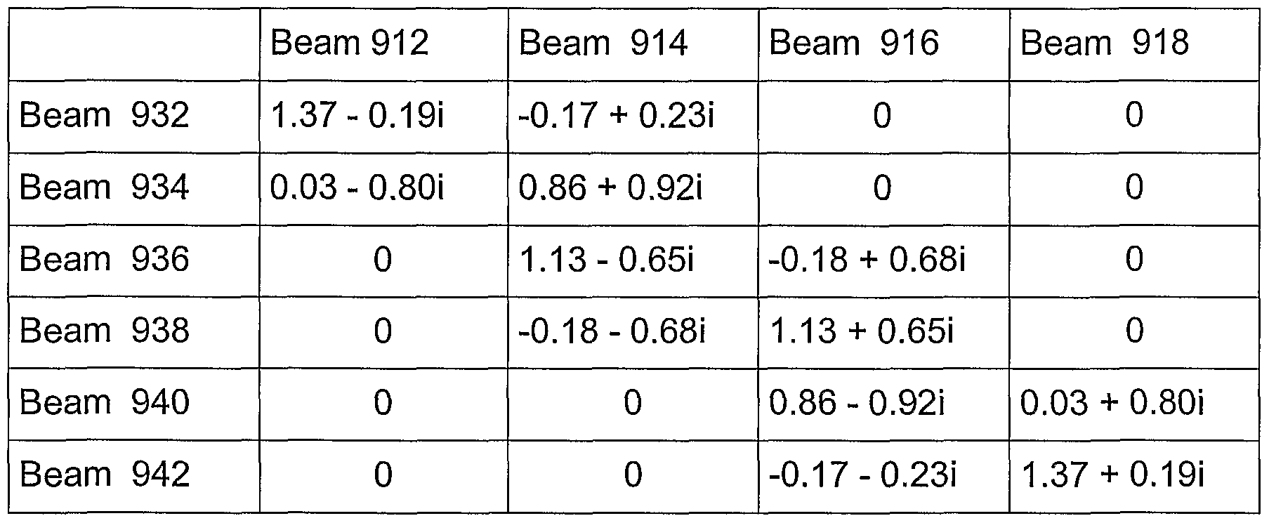
[0055] Figures 9 and 10 provide an example of forming the secondary beam- specific variables 232A, 232B, 232C using the primary beam-specific variables 222A, 222B and the transformation between the primary beams 204A, 204B and the secondary beams 244A, 244B, 244C. Figure 9 illustrates a primary radiation pattern 910 with four primary beams 912 to 918. Figure 10 illustrates a secondary radiation pattern 930 with six primary beams 932 to 942. In Figures 9 and 10, the user equipment 170 transmitting a signal 202 is also shown. The vertical axes 920, 950 show the gain of the radiation patterns 910 and 930, respectively, and the horizontal axes 922, 952 show the azimuth angle of the beam patterns 910, 930 with respect to the antenna array 210. The complex transformation weights carrying out the transformation between the primary beams 204A, 204B and the secondary beams 244A, 244B, 244C are shown, for example, in the following table:
Figure imgf000025_0001
[0056] An assumption may be made, in this example, that the primary beam- specific variables hp n and hp u for the primary beams 912 and 914, respectively, have been determined using the signal 202. By applying the matrix representation given in Equation (10), the secondary beam-specific variable h '934 for the secondary beam 934 can be expressed by means of the primary beam- specific variables hP n and hp 14 as follows:
'93 = hp n (0.03 - 0.80i) + hp u (0.86 + 0.92i) . (10)
[0057] In this case, the transformation may be truncated such that only the primary beams 912, 914 nearest to the secondary beam 934 are used. [0058] According to Figures 9 and 10, the user equipment 170 may be located unfavourably in between the primary beams 912 and 914 in the primary radiation pattern 910; therefore, the downlink transmission using either of the primary beams 912 or 914 of the primary beam pattern 910 may cause a significant loss in gain. However, the gain may be substantially improved when using the secondary beam 934 of the secondary radiation pattern 930 in the downlink. The radio resource can be allocated to the user equipment 170 using the secondary beam specific variable b9 5 34 , which is obtained from the primary beam-specific variables by weighting the variables with predetermined weights. On a general level, the invention enables the resolution of the direction of arrival (DoA) determination to be improved.
[0059] Even though the invention has described above with reference to examples according to the accompanying drawings, it is clear that the invention is not restricted thereto but can be modified in several ways within the scope of the appended claims.

Claims

Claims
1. A method of allocating radio resources in a telecommunication system, wherein the telecommunication system comprises a base station capable of forming antenna beams, the method comprising: transmitting (702) a signal by user equipment, characterized by receiving (704) the signal using at least two primary beams, wherein the signal is used to produce primary beam-specific signals; determining (708) at least two secondary beam-specific variables associated with at least two secondary beams using the primary beam-specific signals and a transformation between primary beams and secondary beams, wherein at least one secondary beam is different from the at least two primary beams; and allocating (710) radio resources to the user equipment based on the secondary beam-specific variables.
2. The method of claim 1, characterized by allocating (710) the radio resources using the at least one secondary beam.
3. The method of claim ^characterized by transmitting (702) the signal using the user equipment, wherein the signal comprises a predetermined symbol sequence; and determining (708) the secondary beam specific variables using the symbol sequence.
4. The method of claim 1, characterized by determining (708) the secondary beam-specific variables as estimates of at least one of a channel impulse response, an averaged channel impulse, a wide band power, a narrow band power, a signal-to-noise ratio, a signal-to-interference ratio, and a signal-to-interference-and-noise ratio.
5. The method of claim ^ characterized by receiving (604) the signal using at least two antenna elements in an antenna array to produce primary antenna-element-specific signals; and transforming (606) at least two primary antenna-element-specific signals into the primary beam-specific signals using primary antenna weights associated with the at least two primary beams.
6. The method of claim 1, characterized by determining (608) at least two primary beam-specific variables using the primary beam- specific signals; and forming (610) the secondary beam-specific variables using the primary beam-specific variables and the transformation between the primary beams and the secondary beams.
7. The method of claim 1, characterized by forming (706) secondary beam-specific signals associated with the at least two secondary beams using the primary beam-specific signals and the transformation between the primary beams and the secondary beams; and determining (708) the at least two secondary beam-specific variables using the secondary beam-specific signals.
8. The method of claim 1, characterized by determining (802) at least two secondary beam-specific quality variables; and selecting (804) at least one secondary beam for radio resource allocation based on the secondary beam-specific quality variables.
9. The method of claim 1, characterized by estimating an estimated direction of arrival of the signal received by the at least two primary beams using the at least two secondary beam-specific variables; and allocating (612) the radio resources to the estimated direction.
10. The method of claim 1, characterized by generating (806A) at least one user signal to be transmitted to the user equipment; and transmitting (808A) the at least one user signal to the user equipment in a secondary antenna beam direction by weighting the at least one user signal with antenna weights associated with the secondary antenna beam direction.
11. The method of claim 1, characterized by receiving (806B) an uplink user signal from the user equipment using at least two antenna elements of an antenna array to produce primary antenna-element- specific user signals; and transforming (808B) the primary antenna-element-specific user signals into at least one secondary uplink beam-specific user signal using secondary antenna weights associated with the secondary beams and the at least two secondary beam-specific variables.
12. The method of claim 1, characterized by adapting the allocation of the radio resources to prevailing requirements of the telecommunication system.
13. The method of claim 1, characterized by providing the transformation between the primary beams and the secondary beams comprising pre-determined complex weights, wherein the complex weights accounts for at least one of primary antenna weights, antenna geometry, carrier frequency associated with primary beams, and carrier frequency associated with secondary beams.
14. A telecommunication system, comprising: a base station (200) and user equipment (170), wherein the base station (200) comprises an antenna array (210) for providing a radio link for signals transmitted between the base station (200) and the user equipment (170), and beam forming means (220) connected to the antenna array (210) for forming antenna beams, c h a r a c t e r i z e d in that the beam forming means (220) are configured to form at least two primary beams (204A, 204B) for signal reception using primary antenna weights and the antenna array (210); the user equipment (170) is configured to transmit a signal (202); the antenna array (210) and the beam forming means (220) are configured to receive the signal (202) using the at least two primary beams (204A, 204B), wherein the signal (202) is used to produce primary beam- specific signals (214A, 214B) as an output; the base station (200) comprises processing means (230) connected to the beam forming means (220) for determining at least two secondary beam-specific variables associated with at least two secondary beams (244A, 244B, 244C) using the primary beam-specific signals (214A, 214B) as an input and a transformation between the primary beams (204A, 204B) and the secondary beams (244A, 244B, 244C), wherein at least one secondary beam (244A, 244B, 244C) being different from any one of the primary beams (204A, 204B); and the base station further comprises allocation means (240) for allocating radio resources to the user equipment (170) based on the secondary beam-specific variables.
15. The telecommunication system of claim 14, c h a r a c t e r i z e d in that the beam forming means (220) are configured to form at least one secondary beam (244A, 244B, 244C); and the allocation means (240) are configured to allocate the radio resources using the secondary beam (244A, 244B, 244C).
16. The telecommunication system of claim 14, characterized in that the user equipment (170) is configured to transmit a signal including a predetermined symbol sequence; and the processing means (230) are configured to determine the at least two secondary beam-specific variables using the predetermined symbol sequence.
17. The telecommunication system of claim 14, characterized in that the secondary beam-specific variables are estimates of at least one of a channel impulse response, an averaged channel impulse, a wide band power, a narrow band power, a signal-to-noise ratio, a signal-to-interference ratio, and a signal-to-interference-and-noise ratio.
18. The telecommunication system of claim 14, characterized in that the antenna array (210) comprises at least two antenna elements for receiving the signal used to produce primary antenna- element-specific signals as the output; and the beam forming means (220) are configured to transform the primary antenna-element-specific signals into primary beam-specific signals (214A, 214B) using primary antenna weights associated with the at least two primary beams (204A, 204B).
19. The telecommunication system of claim 14, characterized in that processing means (230) are configured to determine at least two primary beam-specific variables using the primary beam-specific signals (214A, 214B); and the processing means (230) are configured to form the at least two secondary beam-specific variables using the primary beam-specific variables and the transformation between the primary beams (204A, 204B) and the secondary beams (244A, 244B, 244C).
20. The telecommunication system of claim 14, characterized in the that processing means (230) are configured to form secondary beam-specific signals associated with the at least two secondary beams (244A, 244B, 244C) using the primary beam-specific signals (214A, 214B) and the transformation between the primary beams (204A, 204B) and the secondary beams (244A, 244B, 244C); and the processing means (230) are configured to determine the at least two secondary beam-specific variables using secondary beam-specific signals.
21. The telecommunication system of claim 14, characterized in that the processing means (230) are configured to determine at least two secondary beam-specific quality variables; and the allocation means (240) are configured to select at least one secondary beam (244A, 244B, 244C) for radio resource allocation based on the secondary beam-specific quality variables.
22. The telecommunication system of claim 14, characterized in that the processing means (230) are configured to estimate an estimated direction of the signal received by the primary beams (204A, 204B) using the at least two secondary beam-specific variables; and the allocation means (240) are configured to allocate the radio resources to the estimated direction.
23. The telecommunication system of claim 14, characterized in that the base station (200) comprises a user signal generator (250) for generating a user signal to be transmitted to the user equipment (170) using at least one secondary beam (244A, 244B, 244C); and the beam forming means (220) are configured to transmit the user signal to the user equipment (170) using the secondary beam (244A, 244B, 244C) by weighting the user signal with secondary antenna weights associated with the secondary beams (244A, 244B, 244C).
24. The telecommunication system of claim 14, characterized in that the antenna array (210) is configured to receive an uplink user signal from the user equipment (170) using at least two antenna elements of the antenna array (210) to produce primary antenna-element- specific user signals as the output; and the beam forming means (220) and the processing means (230) are configured to transform the primary antenna-element-specific user signals into at least one secondary uplink beam-specific user signal using secondary antenna weights associated with the secondary beam (244A, 244B, 244C) and the at least two secondary beam-specific variables.
25. The telecommunication system of claim 14, characterized in that the allocation means (240) are configured to adapt the allocation of the radio resources to the user equipment (170) to prevailing requirements of the telecommunication system.
26. The telecommunication system of claim 14, characterized in that the processing means (230) are configured to carry out the transformation between the primary beams (204A, 204B) and the secondary beams (244A, 244B, 244C) using pre-determined complex weights, wherein the complex weights accounts for a factor of at least one of primary antenna weights, antenna geometry, carrier frequency associated with primary beams (204A, 204B), and carrier frequency associated with secondary beams (244A, 244B, 244C).
PCT/FI2003/000942 2002-12-26 2003-12-10 Method of allocating radio resources in telecommunication system, and telecommunication system WO2004059881A1 (en)

Priority Applications (2)

Application Number Priority Date Filing Date Title
AU2003285378A AU2003285378A1 (en) 2002-12-26 2003-12-10 Method of allocating radio resources in telecommunication system, and telecommunication system
EP03778366A EP1576745A1 (en) 2002-12-26 2003-12-10 Method of allocating radio resources in telecommunication system, and telecommunication system

Applications Claiming Priority (2)

Application Number Priority Date Filing Date Title
US10/328,191 2002-12-26
US10/328,191 US7277730B2 (en) 2002-12-26 2002-12-26 Method of allocating radio resources in telecommunication system, and telecommunication system

Publications (1)

Publication Number Publication Date
WO2004059881A1 true WO2004059881A1 (en) 2004-07-15

Family

ID=32680767

Family Applications (1)

Application Number Title Priority Date Filing Date
PCT/FI2003/000942 WO2004059881A1 (en) 2002-12-26 2003-12-10 Method of allocating radio resources in telecommunication system, and telecommunication system

Country Status (4)

Country Link
US (1) US7277730B2 (en)
EP (1) EP1576745A1 (en)
AU (1) AU2003285378A1 (en)
WO (1) WO2004059881A1 (en)

Cited By (1)

* Cited by examiner, † Cited by third party
Publication number Priority date Publication date Assignee Title
CN100459600C (en) * 2005-03-16 2009-02-04 华为技术有限公司 Method and system of access of internet interlock

Families Citing this family (25)

* Cited by examiner, † Cited by third party
Publication number Priority date Publication date Assignee Title
US7406335B2 (en) * 2003-01-13 2008-07-29 Lucent Technologies Inc. Multiple antenna transmissions with deterministic phase differences
US7792547B1 (en) 2003-02-05 2010-09-07 Nortel Networks Limited Downlink and uplink array and beamforming arrangement for wireless communication networks
US20050043030A1 (en) * 2003-08-22 2005-02-24 Mojtaba Shariat Wireless communications system
US20060094485A1 (en) * 2004-10-28 2006-05-04 Interdigital Technology Corporation Method and apparatus for preventing communication link degradation due to the detrimental orientation of a mobile station
US20060094449A1 (en) * 2004-10-28 2006-05-04 Interdigital Technology Corporation Method and apparatus for preventing communication link degradation due to the disengagement or movement of a self-positioning transceiver
CN101138186A (en) * 2005-03-14 2008-03-05 日本电气株式会社 Wireless communication system, transmitting apparatus, transmitting method, program, and recording medium
US7844232B2 (en) * 2005-05-25 2010-11-30 Research In Motion Limited Joint space-time optimum filters (JSTOF) with at least one antenna, at least one channel, and joint filter weight and CIR estimation
US7489944B2 (en) * 2005-06-01 2009-02-10 Alcatel-Lucent Usa Inc. Method of allocating power over channels of a communication system
CN100388846C (en) * 2005-07-08 2008-05-14 中兴通讯股份有限公司 Downlink beamforming method in mobile communication intelligent antenna system
KR101292814B1 (en) * 2005-09-28 2013-08-02 한국전자통신연구원 Method for Maximal Ratio Combining of Spatially Filtered Signals and Apparatus therefor
EP2074708B1 (en) * 2006-10-02 2011-04-20 Koninklijke Philips Electronics N.V. Efficient cqi signaling in mimo systems with variable numbers of beams
EP2171876B1 (en) * 2007-06-28 2019-09-04 Bittium Wireless Oy Transceiver of multi-antenna telecommunication system
WO2013066220A1 (en) * 2011-10-31 2013-05-10 Telefonaktiebolaget L M Ericsson (Publ) A method and a radio base station for antenna/network reconfiguration
US9466869B2 (en) * 2013-09-06 2016-10-11 Empire Technoogy Development Llc Optimal direction determination of radio signals
WO2015109457A1 (en) 2014-01-22 2015-07-30 Empire Technology Development Llc Adaptively selecting from among multiple base stations
PL3462798T3 (en) 2014-03-25 2022-04-04 Telefonaktiebolaget Lm Ericsson (Publ) System and method for beam-based physical random-access
US10250309B2 (en) * 2016-03-24 2019-04-02 Huawei Technologies, Co., Ltd. System and method for downlink channel estimation in massive multiple-input-multiple-output (MIMO)
US10425138B2 (en) 2016-05-26 2019-09-24 Qualcomm Incorporated System and method for beam switching and reporting
US10541741B2 (en) * 2016-05-26 2020-01-21 Qualcomm Incorporated System and method for beam switching and reporting
US10181891B2 (en) 2016-05-26 2019-01-15 Qualcomm Incorporated System and method for beam switching and reporting
US10498406B2 (en) 2016-05-26 2019-12-03 Qualcomm Incorporated System and method for beam switching and reporting
US10651899B2 (en) 2016-05-26 2020-05-12 Qualcomm Incorporated System and method for beam switching and reporting
US10917158B2 (en) * 2016-05-26 2021-02-09 Qualcomm Incorporated System and method for beam switching and reporting
WO2018133117A1 (en) * 2017-01-23 2018-07-26 Telefonaktiebolaget Lm Ericsson (Publ) Method and controller for receiving beam control in mimo system as well as radio unit and base station
KR20190070146A (en) 2017-12-12 2019-06-20 삼성전자주식회사 Apparatus and method for transmitting or receiving signal using beamforming in wireless communication system

Citations (3)

* Cited by examiner, † Cited by third party
Publication number Priority date Publication date Assignee Title
EP0786914A2 (en) * 1996-01-27 1997-07-30 Motorola Ltd A space division multiple access radio communication system and method for allocating channels therein
WO2000021216A2 (en) * 1998-08-11 2000-04-13 The Boeing Company Beam overloading solution for overlapped fixed beams
US6075484A (en) * 1999-05-03 2000-06-13 Motorola, Inc. Method and apparatus for robust estimation of directions of arrival for antenna arrays

Family Cites Families (35)

* Cited by examiner, † Cited by third party
Publication number Priority date Publication date Assignee Title
US5515378A (en) * 1991-12-12 1996-05-07 Arraycomm, Inc. Spatial division multiple access wireless communication systems
US6038459A (en) * 1992-10-19 2000-03-14 Nortel Networks Corporation Base station antenna arrangement
US5576721A (en) * 1993-03-31 1996-11-19 Space Systems/Loral, Inc. Composite multi-beam and shaped beam antenna system
GB2281012B (en) * 1993-08-12 1998-04-15 Northern Telecom Ltd Angle diversity for multiple beam antenna
TW351886B (en) * 1993-09-27 1999-02-01 Ericsson Telefon Ab L M Using two classes of channels with different capacity
US5600436A (en) * 1994-01-05 1997-02-04 Caterpillar Inc. Apparatus and system for determining terrestrial position
GB2295524A (en) * 1994-11-28 1996-05-29 Northern Telecom Ltd Beamed antenna system for a cellular radio base station
US5594447A (en) * 1995-01-11 1997-01-14 Mitsubishi Denki Kabushiki Kaisha Moving target identifying system in a base station radar unit for specifying information about moving targets carrying a mobile station radar unit
FI105430B (en) * 1995-05-24 2000-08-15 Nokia Networks Oy Base station equipment and method for directing antenna beam
US5563610A (en) * 1995-06-08 1996-10-08 Metawave Communications Corporation Narrow beam antenna systems with angular diversity
US6421543B1 (en) * 1996-01-29 2002-07-16 Ericsson Inc. Cellular radiotelephone base stations and methods using selected multiple diversity reception
US5898928A (en) * 1996-02-29 1999-04-27 Telefonaktiebolaget Lm Ericsson Adaptive frequency allocation in a telecommunication system
US6512481B1 (en) * 1996-10-10 2003-01-28 Teratech Corporation Communication system using geographic position data
US5754138A (en) * 1996-10-30 1998-05-19 Motorola, Inc. Method and intelligent digital beam forming system for interference mitigation
GB2320618A (en) * 1996-12-20 1998-06-24 Northern Telecom Ltd Base station antenna arrangement with narrow overlapping beams
US6094165A (en) * 1997-07-31 2000-07-25 Nortel Networks Corporation Combined multi-beam and sector coverage antenna array
US6138012A (en) * 1997-08-04 2000-10-24 Motorola, Inc. Method and apparatus for reducing signal blocking in a satellite communication system
US6694154B1 (en) * 1997-11-17 2004-02-17 Ericsson Inc. Method and apparatus for performing beam searching in a radio communication system
KR100287059B1 (en) * 1997-12-24 2001-04-16 정선종 Structure of mobile active antenna system and satellite tracking method using the same
US5952965A (en) * 1998-07-21 1999-09-14 Marconi Aerospace Systems Inc. Advanced Systems Division Adaptive main beam nulling using array antenna auxiliary patterns
JP3167682B2 (en) * 1998-09-28 2001-05-21 三洋電機株式会社 Radio apparatus having transmission directivity and control method therefor
US6233466B1 (en) * 1998-12-14 2001-05-15 Metawave Communications Corporation Downlink beamforming using beam sweeping and subscriber feedback
US6377783B1 (en) * 1998-12-24 2002-04-23 At&T Wireless Services, Inc. Method for combining communication beams in a wireless communication system
US6043779A (en) * 1999-03-11 2000-03-28 Ball Aerospace & Technologies Corp. Antenna apparatus with feed elements used to form multiple beams
US6453177B1 (en) * 1999-07-14 2002-09-17 Metawave Communications Corporation Transmitting beam forming in smart antenna array system
US6823174B1 (en) * 1999-10-11 2004-11-23 Ditrans Ip, Inc. Digital modular adaptive antenna and method
GB9926438D0 (en) * 1999-11-08 2000-01-12 Nokia Networks Oy A method of reducing transmission power in a wireless communication system
FI20000476A0 (en) * 2000-03-01 2000-03-01 Nokia Networks Oy A method for improving radio communication performance
US6879845B2 (en) * 2000-12-01 2005-04-12 Hitachi, Ltd. Wireless communication method and system using beam direction-variable antenna
BR0017138A (en) * 2000-12-23 2002-11-19 Nokia Corp Base station for a radiocommunication network, base station module for a base station, and method for intensifying angular resolution in estimating uplink signal arrival direction at a base station of a radiocommunication network
US7103022B2 (en) * 2001-02-14 2006-09-05 Ntt Docomo, Inc. Communication control method and apparatus in mobile communication system
US20030064683A1 (en) * 2001-09-28 2003-04-03 Matthews Keith W. On board testing unit for multi-beam satellite and method of testing a satellite
CA2466922A1 (en) * 2001-11-09 2003-05-15 Ems Technologies, Inc. Beamformer for multi-beam broadcast antenna
KR100447411B1 (en) * 2001-12-26 2004-09-04 한국전자통신연구원 Apparatus and method for locating a mobile tranceiver
US7069052B2 (en) * 2002-11-04 2006-06-27 Nokia Corporation Data transmission method in base station of radio system, base station of radio system, and antenna array of base station

Patent Citations (3)

* Cited by examiner, † Cited by third party
Publication number Priority date Publication date Assignee Title
EP0786914A2 (en) * 1996-01-27 1997-07-30 Motorola Ltd A space division multiple access radio communication system and method for allocating channels therein
WO2000021216A2 (en) * 1998-08-11 2000-04-13 The Boeing Company Beam overloading solution for overlapped fixed beams
US6075484A (en) * 1999-05-03 2000-06-13 Motorola, Inc. Method and apparatus for robust estimation of directions of arrival for antenna arrays

Cited By (1)

* Cited by examiner, † Cited by third party
Publication number Priority date Publication date Assignee Title
CN100459600C (en) * 2005-03-16 2009-02-04 华为技术有限公司 Method and system of access of internet interlock

Also Published As

Publication number Publication date
US7277730B2 (en) 2007-10-02
EP1576745A1 (en) 2005-09-21
AU2003285378A1 (en) 2004-07-22
US20040204111A1 (en) 2004-10-14

Similar Documents

Publication Publication Date Title
US7277730B2 (en) Method of allocating radio resources in telecommunication system, and telecommunication system
JP4344133B2 (en) Adaptive beam shaping using feedback signals
EP1723744B1 (en) A method and apparatus for received signal quality estimation
US7203246B2 (en) Method of estimating a channel, and a radio system
EP1182728B1 (en) Adaptive antenna reception apparatus
JP5047429B2 (en) Adaptive antenna array method and apparatus for use in a multiple access wireless communication system
JP4091601B2 (en) Apparatus and method for forming forward transmission beam of smart antenna in mobile communication system
JP4131702B2 (en) Reduce interference using a simple antenna array
US7359733B2 (en) Beam synthesis method for downlink beamforming in FDD wireless communication system
US6584302B1 (en) Method and arrangement for forming a beam
US7054664B2 (en) Method and apparatus for providing user specific downlink beamforming in a fixed beam network
JP3092798B2 (en) Adaptive transceiver
US6377812B1 (en) Combined power control and space-time diversity in mobile cellular communications
EP1496628B1 (en) Mobile communication system, mobile station, base station, communication path quality estimation method used for the same
JP4038408B2 (en) Wireless communication system, base station, and wireless communication method
US7782987B2 (en) Method and apparatus for received signal quality estimation
JP3987738B2 (en) Channel configuration method in mobile communication system, radio base station, mobile station, and mobile communication system
JPH08274687A (en) Cdma radio transmission equipment and cdma radio transmission system
EP1889454B1 (en) Method and system for transmitter beamforming
JP2004509534A (en) Smart antenna without phase calibration for CDMA reverse link
JP2002542657A (en) Downlink beamforming method for base station in wireless communication system
EP1977529A1 (en) Apparatus and method for controlling dynamic range of weight vectors according to combining methods in a mobile station equipped with multiple antennas in high rate packet data system using code division multiple access scheme
JP4100996B2 (en) WEIGHT ESTIMATION METHOD, WEIGHT ESTIMATION DEVICE, INTERFERENCE RELEASE DEVICE AND RECEPTOR HAVING THE SAME
JP4153208B2 (en) Base station antenna directivity control apparatus in CDMA system and base station antenna directivity control apparatus in CDMA cellular system
JP2004509484A (en) Method and apparatus for evaluating uplink radio signals

Legal Events

Date Code Title Description
AK Designated states

Kind code of ref document: A1

Designated state(s): AE AG AL AM AT AU AZ BA BB BG BR BW BY BZ CA CH CN CO CR CU CZ DE DK DM DZ EC EE EG ES FI GB GD GE GH GM HR HU ID IL IN IS JP KE KG KP KR KZ LC LK LR LS LT LU LV MA MD MG MK MN MW MX MZ NI NO NZ OM PG PH PL PT RO RU SC SD SE SG SK SL SY TJ TM TN TR TT TZ UA UG US UZ VC VN YU ZA ZM ZW

AL Designated countries for regional patents

Kind code of ref document: A1

Designated state(s): BW GH GM KE LS MW MZ SD SL SZ TZ UG ZM ZW BW GH GM KE LS MW MZ SD SL SZ TZ UG ZM ZW AM AZ BY KG KZ MD RU TJ TM AT BE BG CH CY CZ DE DK EE ES FI FR GB GR HU IE IT LU MC NL PT RO SE SI SK TR BF BJ CF CG CI CM GA GN GQ GW ML MR NE SN TD TG

DFPE Request for preliminary examination filed prior to expiration of 19th month from priority date (pct application filed before 20040101)
121 Ep: the epo has been informed by wipo that ep was designated in this application
WWE Wipo information: entry into national phase

Ref document number: 2003778366

Country of ref document: EP

WWP Wipo information: published in national office

Ref document number: 2003778366

Country of ref document: EP

NENP Non-entry into the national phase

Ref country code: JP

WWW Wipo information: withdrawn in national office

Country of ref document: JP