APPARATUS AND METHOD FOR SPARE CAPACITY ALLOCATION
RELATED APPLICATIONS
[0001] The present application claims the priority benefit of U.S. Provisional Patent
Application entitled "SPARE CAPACITY ALLOCATION METHOD. ANALYSIS AND ALGORITHMS. Ser. No. 60/224,246 filed August 10, 2000.
STATEMENT REGARDING FEDERALLY SPONSORED RESEARCH
[0002] This invention was made with government support under NSF Contract No.
NCR-9506652 and DARPA Contract No. F30602-97-1-0257. The government may have certain rights in this invention.
FIELD OF THE INVENTION
[0003] The present invention relates generally to techniques for improving network survivability and more particularly to techniques for determining a spare capacity allocation and techniques for optimizing a network restoration scheme.
BACKGROUND
[0004] Telecommunication networks occupy a critical role in today's society. The failure of a network, such as a telephone network, a medical database network, a banking computer network, a military network, an air traffic control network or the Internet, among others, could have catastrophic consequences.
[0005] Most networks are comprised of multiple nodes (such as computers, routers, servers, and switching devices, among others) interconnected by multiple links (such as fiber optic cables and wireless relay stations, among others). Information (such as network status information, user data, and component address information, among others) originates at a source node, flows over a set of sequentially connected links, and terminates at a destination node. A node may act as both a source node and a destination node. For example, a computer (source node) requests information from a router (destination node) over a fiber optic cable (link). The router (now acting as the source node) sends the requested information back over the fiber optic cable (link) to the computer (now acting as the destination node). A
source node and its corresponding destination node are referred to as a "node pair". It should be noted that the terms "data," "traffic," and "traffic demand" are intended to be synonymous with the term "information" hereinafter.
[0006] The route traveled by the information from the source node to the destination node is called a "path." A path may include the source and destination nodes and one or more links. Furthermore, the path may contain intermediate nodes which pass the information to the next link or node. The path that is normally used for communication by a node pair is called the working path. Most networks establish the shortest path between the source node and the destination node as the working path. Thus, a route requiring one link to connect a node pair is preferred as the working path over a route requiring two links to connect the node pair.
[0007] A failure in any network component along a path, however, may prevent communication between the node pair. For example, a link that has failed within the working path will not allow information from the source node to reach the destination node. One or more component failures can easily cripple a network, thereby causing widespread communication failures. Network designers, to create a "survivable network", establish backup paths which act as detours when a component in the working path fails. The ability of a network to continue operating after a failure is known as a network's "survivability" or "survivability level".
[0008] Network designers must concentrate on providing cost-efficient spare capacity reservation at an acceptable survivability level. The "survivability level" gauges the percentage of network traffic that can be restored upon a failure. The ratio of the total spare capacity over the total working capacity, called the "network redundancy," is used to measure the cost efficiency of spare capacity allocation. Network redundancy is highly dependent on the network topology, as well as the algorithms used to determine the amount and placement of the spare capacity. It should be noted that "determine", as referred to in this disclosure, is intended to include calculating, inferring, and assuming, among others. The goal of survivable network design is to provide the maximum network survivability at the minimum network redundancy.
[0009] Many techniques have been developed and implemented to maximize network survivability. Traditional network survivability techniques have two components: survivable network design and network restoration. These components are complementary to each other and cooperate to achieve seamless service operation (i.e., the prevention of service disruptions) when a network component fails.
[0010] The first component of traditional network survivability techniques is survivable network design. Survivable network design refers to the incorporation of survivability
strategies into the network design phase to mitigate the impact of a set of specific failure scenarios. A major component related to the creation of a survivable network is called spare capacity allocation ("SCA"). SCA refers to providing adequate resources within the network which enable traffic to be rerouted when a specific component fails (a link failure for example).
[0011] Designers face two major challenges related to SCA. The first challenge is determining how much spare capacity should be provisioned for the network. The second challenge is determining where that spare capacity should be located within the network. Several algorithms have been developed to assist designers in meeting these challenges. These algorithms are either classified as centralized or distributed algorithms. Centralized algorithms are implemented by a central controller, or processor, which has global information regarding the network. Centralized networks, although easy to implement, fail to adequately deal with the dynamic bandwidth provisioning and traffic fluctuations present in current networks such as ATM backbone networks and the Internet. Distributed algorithms, on the other hand, are implemented within each node in which network traffic travels. Distributed algorithms adequately address dynamic bandwidth provisioning and traffic fluctuations, but generally require more resources to implement and are not easily scaled to a changing network. Current algorithms require a large amount of computational time to achieve the desired result. Furthermore, the results obtamed may not accurately approximate the optimal spare capacity requirement.
[0012] Therefore, there exists a need for a backup path routing scheme that is feasible, scalable, adaptive, much faster, and near global optimal in redundancy reduction. [0013] The second component of traditional network survivability techniques is network restoration. Network restoration refers to rerouting traffic flow that has been affected by a network device failure. The affected traffic is detoured using either pre-planned spare capacity routing or dynamic fault-tolerant routing. In pre-planned spare capacity routing, the affected traffic is detoured to backup paths that have adequate spare capacity provisioned in the SCA design phase. Pre-planned spare capacity routing guarantees that service restoration occurs and minimizes the duration of the failure impact. Pre-planned spare capacity routing, however, requires allocating additional spare capacity, some of which may never be used. As such, the cost of implementing pre-planned spare capacity routing is relatively high. [0014] Dynamic fault-tolerant routing, on the other hand, does not have spare capacity pre-allocated in anticipation of a specific failure. Instead, dynamic fault-tolerant routing establishes a backup path after a failure occurs using any available spare capacity. Although service restoration is not guaranteed and the duration and range of the failure impact is not
minimized, dynamic fault-tolerant routing reduces the amount of spare capacity needed, thereby, reducing the implementation cost for the network.
[0015] With both pre-planned and dynamic routing, affected traffic is detoured using path restoration, link restoration, and fragment restoration. Path restoration refers to rerouting traffic within the end nodes (i.e., the source and destination nodes). Path restoration spreads the failure influence to a larger area within the network, but has a slow failure response speed. Link restoration refers to rerouting the traffic in the nodes adjacent to the failure (i.e., not necessarily within the source and destination nodes). Link restoration has a faster failure response speed, but has a significant impact on the area within the network that is close to the failure. Link restoration only patches the "hole" introduced by the failure. Finally, fragment restoration reroutes traffic within the nodes between the traffic end node (i.e., the source or destination node) and the node adjacent to the failure. Fragment restoration falls somewhere between link and path restoration for both the restoration speed and the area impacted by a failure.
[0016] The selection of backup paths in a network restoration scheme is classified either as failure dependent or failure independent. Failure dependent restoration depends on the failure state (i.e., which node or link has failed), meaning that different network failures are protected by different backup paths. It requires the network nodes to save additional network state information to achieve better utilization. Failure independent restoration, on the other hand, does not depend on the failure state, and therefore is easier to implement than failure dependent restoration. However, failure independent restoration usually requires additional spare capacity to implement.
[0017] A need exists, therefore, for a network restoration scheme that is adaptable to the current operational state of the network and is capable of providing a guaranteed level of service restoration without requiring additional spare capacity to implement. [0018] The discussion of the present invention focuses on mesh-type networks. It should be noted, however, that the present invention is applicable to other network types and that the use of mesh-type networks is in no way intended to limit the scope of the present invention. A mesh-type network refers to an at least two-connected plain (or flat) network. Mesh-type networks exist mainly in backbone and interconnection networks and possess great advantages with respect to flexibility, providing survivable intelligence, and the ability to improve utilization.
[0019] Traditional network designers, given traffic demand locations and network QoS requirements, are responsible for several tasks related to mesh-type networks. One task, called "topology design", requires a designer to distribute and interconnect the network nodes and links. Topology design establishes the node locations and the link connectivity within the
network's topology. Nodes and links must be located such that, should a portion of the network fail, the remaining portion of the network remains operational. This network characteristic is defined as two-link, or two-node connectivity. A two-link(node) connected topology has at least two link(node)-disjoint paths between any two origin-destination node pairs. Link-disjoint is discussed later in reference to FIG. 1.
[0020] Another important task, called "network synthesis", requires the network designer to provide sufficient resources (such as bandwidth, buffers, etc.) to transport all of the traffic demand with the guaranteed QoS requirements from the source node to the destination node while minimizing the total network cost. Network synthesis determines the traffic routing and resource dimensioning for the given network topology. Two problems related to network synthesis are resource design (or, capacity design when capacity is the main parameter of interest) and flow assignment. Multi-commodity flow (MCF) models (as are known in the art) are used for these problems. Additional constraints (such as traffic QoS guarantees, node buffer thresholds and link capacity limits, among others) can be applied to the model as well. In many cases, the MCF model is NP-hard (i.e., it is topology-dependent and does not scale with the number of link, number of nodes, and number of node pairs supporting traffic flow). Therefore, the scalability and application of the MCF model requires a good approximation method to find a near optimal solution for the network within a short period of time. [0021] Additionally, designers use approximation methods to solve traditional network design problems and models. Traditional approximation methods include flow deviation, greedy construction, and Lagrangian methods. Modern heuristic methods include Simulated Annealing ("SA"), Genetic Algorithm ("GA") and Tabu Search ("TS") methods. All of these methods are used for network synthesis problems mentioned above. Designers also use mixed integer programming (MIP) models to formulate the networks link/node disjoint requirements, especially the link/node disjoint requirements between a working route and its backup routes. Link/node disjoint characteristics are additional constraints introduced by survivability requirements in the traditional network design problem. All of these approximation methods, however, suffer from one or more drawbacks, such as large computational time requirements and insufficient spare capacity allocation optimization results among others.
[0022] Therefore, a need exists for an approximation method that can quickly and accurately approximate the optimal spare capacity requirement for a network.
SUMMARY
[0023] The present invention offers a method for deriving a backup path routing resource provisioning template for a network. The method is feasible, scalable, adaptive, much faster, and near global optimal in redundancy reduction. The method includes determining a working path for each traffic flow in the network, aggregating the working paths into a first matrix, determining a backup path for each traffic flow, aggregating the backup paths into a second matrix, and deriving the resource provisioning template from the first and second matrices.
[0024] Additionally, the present invention offers a method for determining a minimum spare capacity required for one of a plurality of links in a network. The method includes creating a spare provision matrix and determining the minimum spare capacity required for one of the plurality of links in the network using the spare provision matrix.
[0025] The present invention also offers a method for determining a total spare capacity allocation for a mesh-type network. The method includes creating a spare provision matrix related to the network, and deriving the spare capacity allocation for the network from the spare provision matrix.
[0026] The present invention offers a means for successively approximating the optimal spare capacity allocation needed by a mesh-type network. The method includes selecting a traffic flow and determining the link cost associated with the traffic flow, where the link cost is associated with an incremental spare capacity. The method further comprise determining a backup path using the link cost, and notifying the rest of the network of the backup path. The method is then repeated for a next traffic flow.
[0027] The present invention further offers a method for dynamically creating a fault management table, indexed by link /, that is used by a network having a total number of links equal to L. The method includes storing a failure impact matrix M; within the fault management table, storing a vector V/ within the fault management table, and storing a spare capacity s/ within the fault management table.
[0028] Additionally, the present invention offers an apparatus for operation within a network having a plurality of nodes interconnected by a plurality of links to facilitate a plurality of traffic flows within the network. The apparatus includes an input link carrying information related to the nodes, links, and traffic flows, a processor operable to receive said information from the input link and operable to derive a spare provision matrix from the information, and an output link operable to receive information from the processor and carry the information related to the spare provision matrix to at least one other node.
[0029] Finally, the present invention offers an apparatus for operation within a network having a plurality of nodes interconnected by a plurality of links to facilitate a plurality of
traffic flows within the network. The apparatus includes an input port for carrying information related to the nodes, links, and traffic flows, a processor to receive the information from the input link, to derive a fault management table from the information and to dynamically implement a successive survivability restoration scheme, and an output port to receive information from the processor and output the information related to the fault management table and the successive survivability scheme to at least one other node.
BRIEF DESCRIPTION OF THE DRAWINGS
[0030] FIG. 1 illustrates the construction of a spare provision matrix according to an embodiment of the present invention.
[0031] FIG. 2 illustrates an operational process for creating the spare provision matrix of
FIG. 1 according to an embodiment of the present invention.
[0032] FIG. 3 illustrates a Fault Management Table ("FMT") containing information obtained using a Successive Survivability Routing scheme ("SSR") according to an embodiment of the present invention.
[0033] FIG. 4 illustrates an operational process for a Successive Survivable Routing scheme ("SSR") according to an embodiment of the present invention.
[0034] FIG. 5 illustrates a system 500 used in operation with a network to create a spare provision matrix and implement the Successive Survivable Routing scheme in accordance with an embodiment of the present invention.
DETAILED DESCRIPTION
[0035] The present invention claims priority benefit of U.S. Provisional Patent
Application entitled "SPARE CAPACITY ALLOCATION METHOD, ANALYSIS AND ALGORITHMS", Ser. No. 60/224,246 filed August 10, 2000. The disclosure of the technical papers comprising the provisional application are attached as an appendix and are incorporated herein by reference in their entirety.
[0036] Throughout this disclosure, the term "spare provision matrix" or "provision matrix" will be substituted for the term "spare sharing matrix" which was used in the provisional application. FIG. 1 illustrates a spare provision matrix (C) according to an embodiment of the present invention. The spare provision matrix of FIG. 1 corresponds to the network 100 consisting of five nodes (labeled a through e) interconnected by seven links (numbered 1 through 7) with the given topology. FIG. 1 further illustrates a working-path- link-incidence matrix (A) for the network 100, the transpose of a backup-path-link-incidence matrix (Bτ) for the network 100, a vector (m) 115 representing the capacity requirements for all traffic flows within the network 100, a vector w 105 representing the working capacity
allocation of the network 100, and a vector (s) 110 representing the spare capacity allocation required for all the links within the network 100.
[0037] In the present embodiment, the network 100 is considered as a non-directed network with traffic flows between all the node pairs 101 (i.e., node pairs a-b, a-c, ... d-e). A node pair has a source node ("src") and a destination node ("dst"). It should be noted that a node within the node pair can act as both a source node and as a destination node, however for the present embodiment, the node pair need only be modeled once. The assignment of which node within the node pair is the source or destination for the present embodiment is irrelevant. For example, node "a" is placed in the "src" column and node "b" is placed in the "dst" column for node pair a-b. However, if node "a" was placed in the "dst" column and node "b" was placed in the "src" column, the results would be the same. [0038] Each node pair is given a flow number corresponding to a traffic flow between the nodes in the node pair. For example in the present embodiment, the flow number "l"is assigned to the node pair a-b, whereas the flow number "8" is assigned to the node pair c-d. [0039] The term "link-disjoint," as mentioned above, refers to two traffic flows that do not share a common link in their working paths. Referring to the network in FIG. 1 for example, the traffic flows having a working path a-b-c (using links 1 and 3) is said to be link- disjoint from the traffic flow having a working path e-d (using link 7). [0040] It should be clear to one skilled in the art that the number of nodes and links, their relative topology, and the non-directed traffic flow of the network are chosen only as an exemplary illustration of the present embodiment, and in no way is intended to limit the scope of the present invention. It should also be apparent to one skilled in the art that the present invention can be implemented for any network, regardless of the network's size or topology, among others. Finally, it should be apparent to one skilled in the art that the general layout of the spare provision matrix, or the components used to create the spare provision matrix, may be altered while remaining within the scope of the present invention. [0041] A vector ar - [ar , ar2, ..., ar,ι represents a working path for each node pair 101 having a traffic flow r. For vector ar, r represents the flow number where 1 < r < D, where D is the current number of flows in the network 100. The elements arj are binary indicator functions that are equal to "1", if and only if, the working path of the correspondmg node pair uses link /, where L represents the total number of links in the network 100. Referring to FIG.1 for example, links 3 and 5 are part of the working path for node pair b-d, the sixth flow in the given network. Thus a6 = [0, 0, 1, 0, 1, 0, 0], where only the elements corresponding to links 3 and 5 have a value of 1. The working path is then aggregated with the working paths of the other node pairs into a working-path-link-incidence matrix A = [a , a2 Υ, ..., ar,τ]τ. In a similar manner, a backup path for each node pair is determined and aggregated into backup-
path-link-incidence matrix B. As previously noted, "determine", as referred to in this disclosure, is intended to include calculating, inferring, and assuming, among others. [0042] The working-path-link-incidence matrix, A, for the given network 100 topology is shown in FIG. 1. The matrix A contains ten rows, each row corresponding to the individual traffic flows between node pairs 101. The matrix A also contains seven columns corresponding to links 1 through 7. In addition to aggregating the vectors ar, the matrix A can be directly created. The value "1" is entered into matrix A, if and only if, the traffic flow for the particular node pair traverses the particular link. The value "0" is entered into matrix A if the traffic flow for the particular node pair 101 does not traverse the particular link. For example, traffic flow between node pair a-b is accomplished over link 1. As such, the value "1" is entered into the matrix A location referring to node pair a-b and link 1 (i.e., row 1, col. 1). The value "0" is entered into the matrix A locations representing node pair a-b and links 2-7 (i.e., row 1, cols. 2-7). Likewise, traffic flow between node pair a-c traverses link 1 and link 3. Therefore, the value "1" is entered into the matrix A locations referring to node pair a- c and link 1 (row 2, col. 1) and node pair a-c and link 3 (row 2, col. 3). The value "0" is entered into the matrix A locations representing node pair a-c and the other, non-traversed links. The process is repeated for each node pair 101 to complete the working-path-link- incidence matrix A.
[0043] It should be noted that the present invention can be used in conjunction with any method or algorithm for determining the working path for each node pair. For example, a shortest path algorithm can be used to determine the working paths for each node pair, the working paths then being used to determine the working-path-link-incidence matrix A. [0044] The backup-path-link-incidence matrix, B, is constructed in a manner similar to the manner in which matrix A is constructed. As mentioned above, matrix B can be constructed by aggregating a series of vectors, b b2, ..., bD, that represent backup paths for all the node pairs 101 having a backup traffic flow., as B=[&/, b2 τ, ..., br?]τ. Matrix B can also be directly constructed. The following discussion will be limited to directly constructing the transposed matrix Bτ of said backup path link-incidence matrix B. [0045] Matrix Bτ, for the present embodiment, has seven rows corresponding to links 1 through 7 and ten columns corresponding to the individual traffic flows over the node pairs 101. The value "1" is entered into matrix Bτ, if and only if, the backup traffic flow for the particular node pair 101 traverses the particular link. The value "0" is entered into matrix Bτ if the backup traffic flow for the particular node pair 101 does not traverse the particular link. For example, a backup path is chosen for node pair a-b that uses link 2 and link 4. As such, the value "1" is entered into the backup-path-link-incidence matrix Bτ locations referring to node pair a-b and link 2 (row 2 col. 1) and node pair a-b and link 4 (row 4, col. 1). The value
"0" is entered into the matrix Bτ locations representing node pair a-b and the other, non- traversed links. Likewise, a backup path for node pair a-c is chosen that uses links 2, 5, and 7. The value "1" is entered into the backup-path-link-incidence matrix locations referring to node pair a-c and link 2 (row 2 col. 2), link 5 (row 5, col. 2) and link 7 (row 7, col. 2). The value "0" is entered into the matrix Bτ locations representing node pair a-c and the other, non- traversed links. The process is continued for each node pair 101 until the transposed backup- path-link-incidence matrix Bτ is completed.
[0046] It should be noted that the present invention can be used in conjunction with any method or algorithm for determining the backup path for each node pair 101. For example, a shortest path algorithm can be used to determine the backup path for each node pair 101, the backup paths then being used to determine the backup-path-link-incidence matrix B. [0047] After the working-path-link-incidence matrix A and the backuprpath-link- incidence matrix B are constructed, the spare provision matrix C is determined. In the present embodiment, the spare provision matrix is the found using the equation C = Bτ • Diag(/«) • A, where C represents the spare provision matrix, Bτ represents the transposed backup-path-link- incidence matrix, Diag(/n) converts the vector m 115 to a diagonal square matrix with elements of m in the main diagonal, and A represents the working-path-link-incidence matrix. It should be apparent to those skilled in the art that the vector m can be used to represent network resources other than capacity. For example, the vector m may represent a network's delay, wavelength, and buffer size among others. Changing the quantity that vector m represents also changes the quantity/resource represented by matrix C. Thus, matrix C can be viewed as a resource provisioning template.
[0048] Each element, Cy, in matrix C represents the minimum spare capacity required on link i when linky fails. For the spare capacity matrix C representing the network topology given in FIG. 1, for example, a failure of link #2 requires the following minimum spare capacity for the other links: link 1 = 2 (i.e., dj2 = 2), link 3 = 1 (i.e., C3j2 = 1), link 4 = 1 (i.e., C4,2 = 1), link 5 = 1 (i.e., C5,2 = 1), link 6 = 0 (i.e., C6>2 = 0), and link 7 = 0 (i.e., C7,2 = 0). The network designer, therefore, can determine the minimum amount of spare capacity required for a link i should link/ fail.
[0049] The total working capacity requirement for the network 100 is obtained from the working-path-link-incidence matrix A. The working capacity for said links are represented by a vector w = [wi, w2, ..., wj. The working capacity of a given link i is represented by w,-, where w,- = sum (Ar xmr)for ArΛ for 1 < r ≤ D. In other words, w{ equals the sum of the entries of column i in matrix A if the traffic demands of all node pairs are at the same value of one. The vector w for the given network 100 is w = [2, 2, 3, 1, 2, 1, 2]. The total working capacity
requirement for the network 100 is easily derived by summing the elements in vector w. Therefore, the total working capacity requirement for network 100 is thirteen. [0050] The total, minimum spare capacity requirement for all links in the network 100 is found using vector s = [s s2, • ■ ■ sL], 104 where s{ = max j for 1 <j < L. In other words, st equals the maximum value within the row i of spare provision matrix C. The vector s for the given network 100 is s = [2, 2, 1, 1, 2, 1, 2]. The total spare capacity requirement for the given network 100 is easily derived by summing the elements of vector s. Therefore, the total spare capacity requirement for the network 100 is eleven.
[0051] Several other issues facing the network designer solving the spare capacity allocation problem are represented by the spare provision matrix C. The non-uniform flow demands are easily combined in vector m 115 as shown above. Moreover, for asymmetric traffic demands, directed links must be used in the spare provision matrix C; this doubles L (i.e., the total number of links in the network) and requires each failure scenario to include two links in both directions. Furthermore, the per-flow based state information can be aggregated into spare provision matrix C. If there is traffic flow r with certain working path ar and backup path br, their contribution to the matrix C is a L x L matrix Cr = ar -br T where "•"is a vector product operation which takes a row vector on its left hand side and a column vector on its right hand side to produce a matrix. The spare provision matrix C is easily derived from the summation of the contributions Cr of all flows and it is the only information required for spare capacity sharing in SCA problem. Per-flow based information in A and Bτ are no longer necessary for the spare capacity sharing operation. This not only demonstrates the scalability of the spare provision matrix method, but also provides enhanced privacy among different traffic flows in an opened network environment.
[0052] In the present embodiment, the spare provision matrix C is determined using a computing system having a processor, a memory, an input/output device, and a data storage device among others. The computing system can be any personal computer, mainframe, calculator, switch, router, and relay among others. The processor is any device capable of executing an instruction or series of instructions (for example instructions encoded into a computer program, etc.) to obtain a result. The memory is any device that is capable of storing information such as random-access-memory (RAM), read-only-memory (ROM), dynamic-random-access-memory (DRAM), and flash memory among others. The input/output device is a keyboard, sensor, scanner, touch pad, printer, display, terminal, and wire carrier among others. The data storage device is any optical disc drive, magnetic disc drive and magnetic tape drive among others.
[0053] In the present embodiment, information representing the node pairs, traffic flows, links, and network topology among others is entered into a computer system using an input
device. The information is stored in the memory and data storage device. The processor accesses the information, determines the spare provision matrix (among others), stores the result in the data storage device, and delivers the result to an output device. It should be clear to one skilled in the art, that the spare provision matrix C can be determined manually, through the use of other automated systems, or a through a combination thereof. The description of the present embodiment is in no way intended to limit the scope of the present invention to a specific apparatus of determining the spare provision matrix C. [0054] Fig. 2 illustrates operational process 200 for creating a spare provision matrix according to an embodiment of the present invention. Operational process 200 is initiated by operational process 201. In an embodiment of the present invention, operation 201 is triggered by a user during the network design phase. It should be clear to one skilled in the art that the operational process 200 can be triggered automatically (such as by a computer program among others) and can be triggered at a time other than the network design phase while still remaining within the scope of the present invention.
[0055] Operational control is then assumed by operation 202. Operation 202 sets r equal to 1, where r represents a traffic flow number. In the current embodiment, 1 < r ≤ D where D is the current number of traffic flows in the network. Operational control is then passed to operation 203.
[0056] Operation 203 retrieves the working path for the traffic flow r. The working path contains a source node, a destination node, and an interconnecting working path link. In the current embodiment of the present invention, the working path is previously determined on each individual traffic flow r using methods common in the art, such as a shortest path algorithm among others. Using a shortest path algorithm, the working path is determined to be one of the shortest paths that have link-disjoint alternative paths. It should be noted that other schemes can be used to determine the working path for the traffic flow r. As an alternative to retrieving a previously determined working path for traffic flow r, operation 203 determines the working path for the traffic flow r.
[0057] Operational control is assumed by operation 204 after the working path is retrieved for traffic flow r in operation 203. Operation 204 aggregates the working path of traffic flow r into a first matrix. In the current embodiment, the working path of traffic flow r is aggregated into a working-path-link-incidence matrix. The elements of the working-path- link-incidence matrix represent whether a link is used to carry traffic flow between a specific node pair during normal operation. An element of the working-path-link-incidence matrix is assigned the value "1" if a link is used to carry the traffic flow of the corresponding node pair during normal operation. If the link is not used to carry the traffic flow of the corresponding node pair during normal operation, a value "0" is assigned to the matrix element.
[0058] Operational control is then assumed by operation 205. Operation 205 retrieves the backup path for traffic flow r. The backup path for traffic flow r contains the same source and destination nodes as the working path. The backup path, however, contains a backup path link instead of the working path link. In the current embodiment of the present invention, the backup path is determined prior to implementing operational process 200 using methods common in the art. For example, a shortest path algorithm, in conjunction with the network state and the working path, is used. As such, a backup path will not contain a link that has previously failed or a link that is used by the working path for the particular traffic flow r. The backup path is then stored in a database within the system for retrieval by operation 205. As an alternative to retrieving a previously determined backup path for traffic flow r, operation 205 determines the backup path for the traffic flow r. Operational control is then passed to operation 206.
[0059] Operation 206 aggregates the backup path r found in operation 205 into a second matrix. In the current embodiment, the backup path r is aggregated into a backup-path-link matrix. The elements of the backup-path-link-incidence matrix represent whether a link is used to carry traffic flow between a specific node pair during backup operation. An element of the working-path-link-incidence matrix is assigned the value "1" if a link is used to carry the traffic flow of the corresponding node pair during backup operation. If the link in not used to carry the traffic flow of the corresponding node pair during backup operation, a value "0" is assigned to the matrix element.
[0060] Operational control is then assumed by determination operation 207. Determination operation 207 ascertains whether there are any more traffic flows for which a working path and a backup path need to be retrieved. If the current traffic flow is not the last to have working path and backup path information gathered, operational control branches NO and operation 208 assumes control. Operation 208 adds 1 to the value of r. Operational control is then passed to operation 202, and operations 202 through 207 are repeated. In the current embodiment, a working path and backup path is retrieved for each traffic flow within the network. In an alternative embodiment, a working path and a backup path is determined for less than each traffic flow used by the network. If the current traffic flow is the last to have working path and backup path information gathered, operational control branches YES and operation 209 assumes control.
[0061] Operation 209 creates a spare provision matrix using the first matrix created in operation 204 and the second matrix created in operation 206. In the current embodiment, the working-path-link-incidence matrix and the backup-path-link-incidence matrix are used to produce a spare provision matrix. The spare provision matrix is used to determine the total backup path capacity requirement, among others. The spare provision matrix replaces the
per-flow based information (represented by the working-path-link incidence matrix and the backup-path-link-incidence matrix) is used to perform the spare capacity sharing operation in the network.
[0062] Operational control is then assumed by operation 210. Operation 210 terminates operational process 200.
[0063] FIG. 3 is an illustration of a Fault Management Table ("FMT") containing information obtamed using a Successive Survivability Routing scheme ("SSR") according to an embodiment of the present invention. Each link has an associated FMT stored on the network. For example the FMT of associated with a link is located within the source node of the link or within a central database (among others). The FMT and is used to store and calculate the spare provision matrix C, and further, to find the spare capacity allocation on each link as protection against any single link failure. Information stored within a FMT of link / includes the working paths used by node pairs whose backup path uses this link /, and the minimum spare capacity values required on link / for protecting the failure of any other links. In the present embodiment, the FMT resides on each link, is updated to reflect changing network conditions, and is used during network restoration implementation. [0064] As previously mentioned, network restoration can be accomplished using path restoration techniques. Path restoration refers to rerouting traffic within the source and destination nodes. A problem facing network designers utilizing path restoration is determining the amount of spare capacity and placement of the link-disjoint backup paths necessary to implement the path restoration plan. Network designers use the information within the FMTs as a way to determine a path-link integer programming model for the spare capacity allocation problem of the network.
[0065] The path restoration with link-disjoint backup path problem can be formulated as a path-link model. The path-link model is used to derive several formulas that represent the spare capacity allocation problem face by network designers. The path-link model has design variables that represent the links and the backup paths of the traffic demands on the network's node pairs. A directed graph {Of, L ), where Wand L are the node set and the link set, respectively, is used for a network. The total number of nodes is represented by N= | 5V . Likewise, the total number of links is represented by L = | -£ | . The value c represents the unit cost of link /, for I e £. Furthermore, the value © denotes a set of traffic demand pairs where © c (Wx 5V), and where D = | © | <Nx (N-l) if only bi-directional, point-to-point traffic demand pairs are considered. A traffic demand pair is a node pair consisting of a source and destination node having a traffic demand (i.e., traffic flow) there between.
[0066] In the path-link model, the demand node pair r (where r e ©) requires mr units of traffic demands with a restoration level of y. For an embodiment of the present invention, the following values are assigned: c; = 1, mr = 1, and Y = 100%.
[0067] Each demand node pair r e ©, has a value (p', which denotes a candidate set of loop-free backup paths that are link-disjoint from the given working path. <P is precalculated using methods common in the art. For example in a network without working links, a Floyd- Warshall algorithm (an all-pairs shortest path algorithm) can be used to find all feasible backup paths for all node pairs. Thep0 path in the path set (P~ is represented by a binary path- link indicator δ['p, where δf'p = 1, if and only if, pεά p includes link /. In the current embodiment, only single link failures are assumed; as such, <∑ represents the set of affected traffic demand pairs upon the failure of link The required spare capacity for each backup path is decided by a binary flow allocation variable xr,p, where xr'p = 1, if and only if, path/> in <P~ is used for backup of traffic flow r. The reserved spare capacity si on link is determined from the backup flow allocation xr,p and mr.
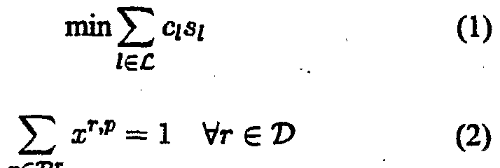
[0068] As previously mentioned, prior art methods use an Integer Programming ("IP") model to represent the spare capacity allocation problem. The following formulas can be derived from the IP model which represent the spare capacity allocation problem. The objective function of the first equation is the minimization of the total cost of the reserved spare capacity for the network. Equation (1) is as follows:
mm Σ c I,s31, (1) fee
[0069] Constraints present in the second equation on the other hand, guarantee that one and only one backup path exists for the traffic demand r. Equation (2) is as follows:
x"'" =\ Vr e © (2)
[0070] The constraints present in equation (3) reflect that the total spare capacity reserved on the link i is the maximum of the total required spare capacity over all failure scenarios involving link /. For example if link 1 is used by backup paths of several node pairs, equation (3) gives the total spare capacity that must be found to restore traffic flow for each node pair that uses link 1. Equation (3) is as follows:
[0071] This IP model formulation is NP-hard. In other words, it is topology-dependent and does not scale with N, L, and D. Therefore, this IP model is difficult to adapt to larger networks.
[0072] In an embodiment of the present invention, _?/ is removed and a new objective formulation with constraints equivalent to that of equation (2) (i.e., that one and only one backup path per traffic demand r) is determined. The new objective function, written as equation (4), is as follows:
[0073] The maximum spare capacity value found within the brackets in equation (4) is easily explained using a fault management table ("FMT"). The FMT contains a matrix Mh a vector Vi, and spare capacity st. It should be clear to one skilled in the art that other information may also be stored in the FMT.
[0074] The matrix Mi, called a failure impact matrix, has (L -1) rows indexed by all the other (L - 1) links in the network. The entity A denotes the index number of selected backup path for a traffic flow r e ©, or equivalently, pr - arg = r (xr'q = 1) . The traffic flows whose backup paths include link / are used to index the columns in /. Such flow set is denoted as
F; = |r : δ['p = 1, r e ©] . The element on row/ and column r, Mf'r , is equal to one or zero depending on whether the working path of traffic flow r e Fi includes link/or not, where/ e
£ - {/}.
[0075] The vector, V;, is a column vector with L - 1 elements. The/th element v/gives the fraffic demand to be restored when link/fails. The minimum spare capacity required on link / when link/fails can be written as: v{ . Therefore, it is clear that the spare
capacity to be reserved on this link, __?
/, is the maximum of the spare capacity required in all failure scenarios. Thus Si is given determined using the equation: s, = max vf . Note that the transpose of said column vector V
/is equivalent to the /-th row vector in spare provision matrix C, hence each FMT table stores and calculates one row vector in spare provision matrix C and all the FMT tables of all links stores all row vectors of spare provision matrix C.
[0076] Referring again to FIG. 3, the FMT illustrated corresponds to link 1 of the network in FIG. 1. For exemplary purposes, it is assumed that there are four flows (flows No. 3, 4, 6, and 7) in the network, having working paths a-e-d, a-e, b-c-d, and b-e respectively, and backup paths a-b-c-d, a-b-e, b-a-e-d, and b-a-e, respectively. In the current embodiment, it is assumed that all the spare capacity of the backup paths for traffic demand r has been reserved and the related FMT tables are up-to-date. Flows 3, 4, 6, and 7 have their backup paths passing through link 1.
[0077] The working path of flow 3 includes link 2 and link 7. The failure of either link 2 or link 7 calls for the spare capacity flow 3 reserved on link 1. Therefore, the entries in the column representing flow 3 and corresponding to links 2 and 7 are assigned the value "1". The links 3-6 in the column representing flow 3 are assigned the value "0". The values for flows 4, 6, and 7 are assigned in the same manner. It should be noted that the values assigned for each flow in set Ft corresponding to each link/ creates a matrix Mi. [0078] The failure of link 2 in the current embodiment requires the spare capacity of m3+mA on link 1, which is the summation of spare bandwidth of all affected flows (here, flows 3 and 4). The spare capacity values required by each link are elements in the vector Vi. The final spare capacity reserved on link 1 is Si, which selects the maximum value in Vi. [0079] Moreover, given Vi and the working path of a new traffic flow r, the incremental spare capacity on flow link / can be calculated. In an embodiment of the present invention, the column for flow r is appended to Mi to create a new failure impact matrix M{. Likewise, a new VI and si are determined. Then incremental spare capacity, If, is determined using the equation If - si - si. The value If represents the potential spare capacity increment if the traffic flow r uses link / in its backup path. The value If is then used in a Successive Survivable Routing scheme ("SSR") to chose a backup path for flow r which further optimizes the spare capacity allocation for the network (i.e., reduces the total spare capacity required by the network). It should be noted that the incremental spare capacity found using the equation If — si - Si guarantees that the amount of total spare capacity approximated by SSR will decrease or stay the same. In other words, the total spare capacity result found using SSR will approach the optimal total spare capacity required by the network. [0080] As previously mentioned, SSR approximates the optimal spare capacity allocation ("SCA") required by a network. SSR routes link-disjoint backup paths for individual traffic flows, one at a time. A backup path is determined for each individual traffic flow according to the current network state, as long as the backup path is not carrying any traffic load. As such, SSR reduces the amount of network redundancy needed through the use of iterative computation. SSR achieves increased computational speed, distributive
implementation, adaptability to traffic fluctuations, and lower redundancy requirements over the entire network.
[0081] In an embodiment of the present invention, a link cost for a backup path corresponding to traffic flow r is calculated from the current network states. The link cost is the incremental spare capacity found using the equation If = si - ■_?/. A backup path for flow r is then determined using the link cost in conjunction with a shortest backup path routing scheme. The backup path is stored in a manner such that the remainder of the network is notified of the backup path for flow r. For example, SSR updates the FMT tables of all the links within the selected traffic flows backup path. A new total spare capacity allocation can then be calculated. Another traffic flow is then selected and the process repeated. For each traffic flow r, each backup path found using SSR guarantees that the total spare capacity found will be lower than (or at least the same as) the total spare capacity before SSR was implemented. The process is successively repeated until the stable spare capacity allocation required by the network is determined. In one embodiment, SSR is used to approximate the optimal SCA for a network modeled by an integer programming ("IP") model. [0082] Fig. 4 illustrates operational process 400 in which SSR, according to an embodiment of the present invention, is implemented. Operational process 400 uses SSR to approximate the optimal total spare capacity for a network. Operational process 400 calculates a link cost (c/) for a traffic flow r from the network states, uses the link cost to determine a backup path for flow r, and notifies the network of the backup path. Operational process 400 then continues for other traffic flows within the network until the optimal spare capacity allocation for the network is determined.
[0083] Operational process 400 is initiated by operation 401. In the current embodiment, operation 401 is programmed to initiate operational process 400 after detecting a change in the network state, such as the occurrence of a network component failure. Alternatively, operation 401 can be programmed to continuously and automatically run within a network by accepting control from operation 405. Likewise, operation 401 can be manually triggered by a user, such as a network designer, administrator, etc.. After operational process 400 is initiated, operational control is then surrendered to operation 402.
[0084] Operation 402 selects a traffic flow. In the current embodiment, the traffic flow is selected randomly from the set of traffic flows. Alternatively, operation 402 can select the fraffic flow using some established criteria (such as selecting a fraffic flow that was affected by a change in the network and selecting a traffic flow that was added to the network, among others). Operational control is then surrendered to operation 403. [0085] Operation 403 assumes control after the current backup path is retrieved.
Operation 403 determines a link cost for the selected traffic flow. In the current embodiment,
operation 403 sets the updated link cost equal to the incremental spare capacity value, If = sf - si, as discussed above.
[0086] Operation 404 assumes control after the link cost is determined for the selected traffic flow. Operation 404 selects a backup path for the selected fraffic flow. In the current embodiment, operation 404 uses the link cost with a shortest path algorithm and the current network state to determine the backup path for the selected fraffic flow. The link cost allows a shortest path algorithm to find a backup path that tries to share the current available spare capacity on the network. In this manner, the total incremental spare capacity for the backup path of the selected node pair is minimized. Likewise, as the SSR scheme is repeated for all traffic flows in the network, the optimal total spare capacity allocation is approximated. It should be clear to one skilled in the art that any shortest path algorithm may be used to determine the backup path based on this link cost for the selected traffic flow while remaining within the scope of the present invention.
[0087] The backup path will have a total link cost that is less than or equal to the total link cost of the current backup path. In the current embodiment, operation 404 minimizes the incremental spare capacity for each backup path. Minimization of the incremental spare capacity is a necessary condition for a optimal multi-commodity-flow ("MCF") solution, because changing any single backup path from the optimal spare capacity allocation solution would only increase the total spare capacity, or equivalently its incremental spare capacity. From this perspective, the incremental spare capacity is used as the link cost of the backup path for each traffic flow. In so doing, distributive backup path routing participates actively in SCA in approximating the optimum. It should be clear to one skilled in the art, however, that other methods may be used to minimize the total link cost of the selected backup path while remaining within the scope of the present invention.
[0088] Operation 405 then assumes control from operation 404. Operation 405 notifies the network that a backup path has been determined for the selected traffic flow. In the current embodiment, operation 405 notifies the network by updating the FMT stored in each node that the backup path uses. It should be clear to one skilled in the art, however, that other notification methods can be employed.
[0089] Determination operation 406 assumes control after the network has been notified by operation 405. Determination operation 406 ascertains whether the spare capacity allocation has stabilized. If the spare capacity allocation has stabilized, operational control branches YES and operation 407 terminates operational process 400. If the spare capacity allocation has not stabilized, operational control branches NO and operation 402 assumes operational control and selects another traffic flow. In one embodiment, operation 406 compares the total spare capacity allocation calculated from the last iteration of operational
process 400 to a spare capacity allocation calculated prior to the last iteration. The difference between these two values are compared the a threshold value set by the network designer. If the last iteration does not improve the networks total spare capacity requirement, operational control branches YES, whereas if an improvement occurs, operational control branches NO. [0090] Alternatively, determination operation 406 can determine whether the last given number of iterations have improved the total spare capacity allocation. Thus, if the iterations have improved the network's spare capacity allocation, then operational control branches YES, else operational control branches NO. It should be appreciated by one skilled in the art that many other methods for determining whether a stable spare capacity approximation has been reached can be used while remaining within the scope of the present invention. [0091] It should be noted that SSR can be implemented in an link state routing protocol
(such as Open Shortest Path First protocol). Each directed link maintains per-flow information in FMT. The aggregated information in vector V/ is advertised periodically. Each node collects all V/ information, forms a spare provision matrix C, and routes backup paths for all the traffic flows originating from it. SSR broadcasts state information at a complexity of 0(L2). Hence, it is scalable with the increasing flow numbers in a network. [0092] The Successive Survivability Routing scheme can be implemented within each node in a distributed manner, within a single processor in a centralized manner, or with a combination of the each node and a single processor. In one embodiment, the Successive Survivability Routing scheme (including updating the fault management table) is implemented within each node in a distributed manner. A node is a computer, mainframe, terminal, switch, router, and relay among others. In the current embodiment, each node possesses a processor, a memory, and an input/output device, among others. [0093] FIG. 5 illustrates a system 500 used in operation with a network to create a spare provision matrix and implement the Successive Survivable Routing scheme in accordance with an embodiment of the present invention. System 500 is comprised of a processor 501, a data storage device 502, an input buffer 503, an output buffer 504, a memory 505 having a database 506 and routing table 507 therein, an input device 508, an output device 509, and input port 510 and an output port 511.
[0094] The system 500 can be implemented in any personal computer, mainframe, calculator, switch, router, and relay among others. The processor 501 is any device capable of accepting input information, executing an instruction or series of instructions (for example instructions encoded into a computer program, etc.), and providing output information, among others. The data storage device 502 is any optical disc drive, magnetic disc drive and magnetic tape drive among others. The input buffer 503, output buffer 504, and memory 505 is any device capable of storing information such as random-access-memory (RAM), read-
only-memory (ROM), dynamic-random-access-memory (DRAM), and flash memory among others. The database 506 contains information relating to the nodes, link, traffic flows, and network state, among others. The routing table 507 contains information relating to the paths used by traffic flows, the network state, and the network topology, among others. The input device 508 and output device 509 is any keyboard, sensor, scanner, touch pad, printer, display, terminal, modem, and wire carrier, among others. The input port 510 and the output port 511 can be any type of connection capable of receiving or outputting information as is known in the art. Although one embodiment of the system is shown, it should be clear to one skilled in the art that other embodiments are possible. For example, the input device and output device can be combined into one device, the database and routing table can be combined into one data structure, and the input and output buffers can by combined into one buffer, among others.
[0095] The above-described embodiments of the invention are intended to be illustrative only. Numerous alternative embodiments may be devised by those skilled in the art without departing from the scope of the following claims.
SPARE CAPACITY ALLOCATION METHOD , ANALYSIS AND ALGORITHMS
PART 2
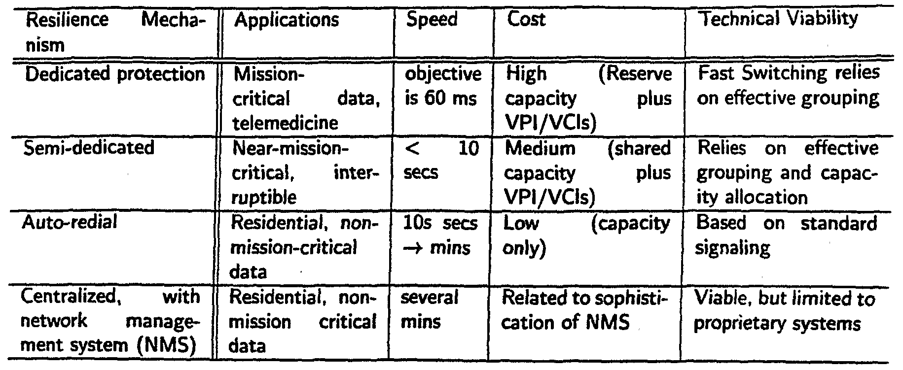
Abstract — Spare capacity allocation (SCA) is an imporcentralized planning on circuit-switching networks such as tant component for providing survivable network services public switched telephone networks [I], SONET/SDH [2], to guarantee seamless communications with minimum QoS [3], [4], ATM [5], [6], [7], and WDM networks [8], loss upon failures. As a multi-commodity flow problem, SCA [9]. However, circuit-switching backbone networks are is NP-hard and various approximation algorithms have been being replaced or overlapped with packet-switching netproposed to reduce network redundancy for a given surworks which provide better manageability on bandwidth vivability level. An on-line algorithm, successive survivable routing (SSR), is proposed in this paper to approximate the granularity and connection types. This architecture mioptimal SCA solution. The algorithm routes link-disjoint gration happens with the explosive expansion of Interbackup paths for individual traffic flows, one at a time. Each net services. In addition to traditional requirements of traffic flow keeps updating its backup path according to the cost-effectiveness and service survivability, the increascurrent network state as long as the backup path is not caring Internet traffic and its flexible QoS requirements rying any traffic load. This allows network redundancy to be have brought in many new issues such as scalability and reduced through distributive online computation. SSR can dynamic bandwidth provisioning for fluctuating traffic, be implemented by shortest path algorithms using advertised link information with complexity of 0{L2) instead of lϊierefore, it is of increasing importance and necessity for per-flow based information, where L is the number of links network survivability research to catch up this trend. Some in a network. Based on an integer programming formulation initial efforts have been made in this direction, for examfor SCA, SSR is compared with other traditional algorithms ple, various fault-tolerant routing schemes are studied in such as branch and bound (BB), simulated annealing (SA), RSVP-based IntServ services [10] and IP/MPLS backbone and resource aggregation fault tolerance (RAFT) on eight networks [11]. These methods focus on protecting workmesh-type networks with the sizes ranging from 10 to 50 nodes. SSR has redundancy values much lower than RAFT, ing traffic by reserving spare bandwidth in backup paths. comparable to SA and only a little bit higher than BB. For Though network redundancy is reduced to some degree by all eight networks, SSR find solutions within one second as sharing spare bandwidth, it is the interest of this paper to RAFT does, while BB takes minutes to hours and SA takes have redundancy minimization as an optimization criterion at least minutes. In conclusion, SSR has advantages in terms without deteriorating the benefits of backup path routing. of its computation speed, distributed implementation, adapIn fact, our results show that our backup path routing is not tive to traffic fluctuation, and capability in achieving lower only feasible, scalable, adaptive, much faster, but also near redundancy over the entire network. These attractive properties are supportive evidence for the application of SSR to global optimal in redundancy reduction. the next generation Internet as well as other mesh-type netThis paper is organized as follows. Section II overviews works. existent survivability techniques and SCA algorithms. I
Keywords — network survivability, spare capacity alloSection HI, an IP formulation of SCA is introduced and its cation, survivable routing, network optimization, multi- best solution with hop-limited path sets is solved by a comcommodity flow, online algorithm, simulated annealing mercial Branch and Bound (BB) solver AMPL/CPLEX. A Simulated Annealing (SA) algorithm is implemented in
1. INTRODUCTION Section IV to approximate the optimal solution of the IP
Network survivability techniques have been widely used model. The main contribution is in Section V. First, a to guarantee the seamless provision of the communicasuccessive survivable routing (SSR) scheme is developed tion services upon network failures. Most of them use as an on-line algorithm to approach the IP optimum. The implementation issues and computational complexity are
Supported in part by DARPA under No. F30602-97-1-0257 and NSF discussed. In Section VI, the proposed distributive method grant NCR-9506652 is compared with several centralized algorithms on eight
networks. Numerical results show that the solutions found of the total spare capacity over the total working capac¬ by our method are comparable to SA's and very close to ity. It highly depends on the network topology as well as BB's. While those algorithms take at least minutes, our the spare capacity allocation algorithms used. For exam¬ SSR takes less than one second. Section VII concludes the ple, a self healing ring (SHR) topology have 100% redun¬ dancy [2], [3]. In mesh-type networks, because working paper. paths are in general the shortest paths, more than 100% re¬
II. RELATED WORKS dundancy is needed in reserving backup paths. However, the redundancy can be reduced by sharing spare capacity A. Traditional network survivability techniques reservation and this overloading is feasible only when re¬
Traditional network survivability techniques have two lated failure scenarios are non-overlapping in the network. aspects, survivable network design and network restoraA failure scenario includes all the simultaneously failed tion [12]. These two phases are complementary to each network devices or components. In this paper, we consider other and cooperating to achieve seamless service operathe failure scenarios where only one network link can fail tion upon failures. at one time. This single link failure assumption provides
Survivable network design refers to the incorporation the maximum number of nonoverlapping failure scenarios. of survivability strategies into the network design phase According to the initialization locations of the rerouting in order to mitigate the impact of a set of specific failure process, restoration schemes are classified as link restorascenarios. Spare capacity assignment is the major compotion and path restoration. In link restoration, the nodes nent in dimensioning a survivable network when ihe netadjacent to a failed link are responsible for rerouting the work topology is given. It ensures enough spare capacity affected traffic flows. Thus it only patches the losing link for the physical network or the virtual network to recover in the original path. In contrast, in path restoration, the from a failure via traffic rerouting. For example, given end nodes whose traffic is traversing the failed link are inia SONET/SDH mesh-type network topology, the normal tiating the rerouting process. In general, path restoration traffic demand with their flow allocation, the problems are requires less spare capacity reservation than link restorahow much spare capacity should be provisioned and where tion [17]. Moreover, the selection of backup paths can it should be located in order for the network to tolerate a be failure dependent when different failures are protected specified set of failure scenarios (e.g., loss of any single by different backup paths. A failure independent path link). The term mesh-type doesn't imply that the network restoration scheme, which normally requires a backup path topology is a full mesh, but rather that the network nodes link-disjointed from the working path, requires less sigare at least two-connected [13], [14]. naling support and is easier in implementation while it
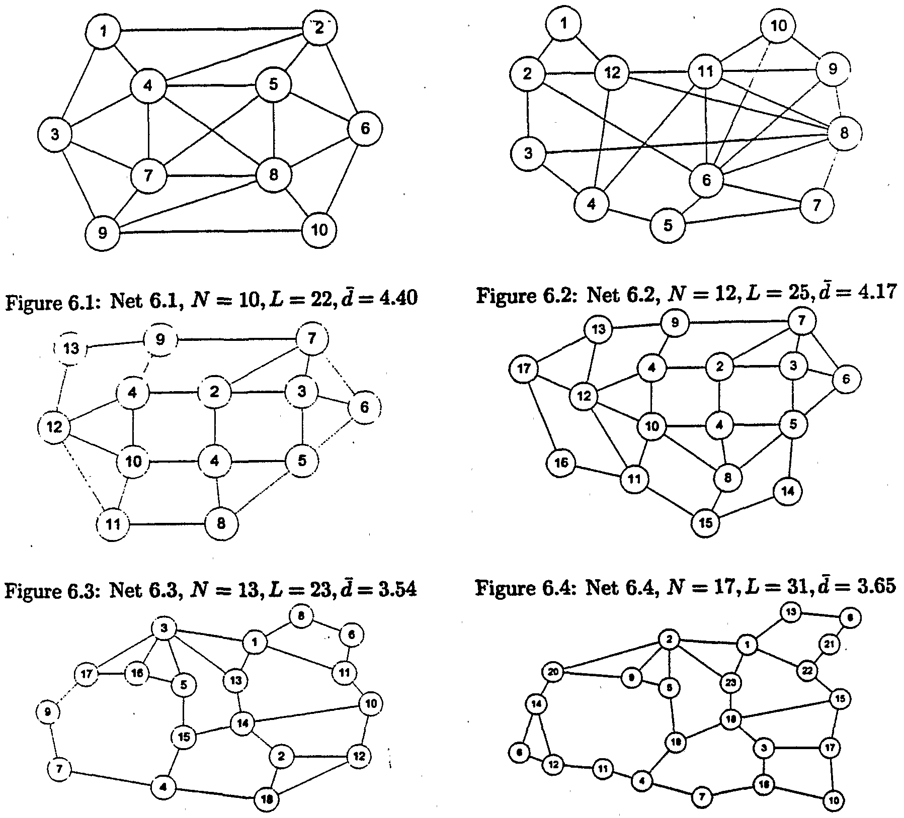
In network restoration, affected traffic demand pairs are might require more spare capacity than failure dependent rerouted upon failure to backup paths that have enough path restoration. In this paper, we use link-disjoint backup spare capacity provisioned in the survivable network depaths in our path restoration. sign phase. Compared to dynamic fault-tolerant routing Another problem arises in the failure independent path where no spare capacity is pre-allocated before failure, restoration is called trap topology [18], [4]. In a trap topolpre-planning spare capacity not only guarantees service ogy, the working path may block all the possible link- restoration, but also minimizes the duration and range of disjoint backup paths although the network topology is the failure impact. In packet-switching networks, such two-connected. The Network 5 and 6 in Section VI have service guarantees are especially important because back-' such trap topologies. For example, the traffic flow between log traffic accumulated during the failure restoration phase node 13 and node 15 in Network 6 have shortest workmight introduce significant congestion [15], [16]. Preing path via nodes 1 and 22. This path does not have any planning spare capacity can mitigate or even avoid this link-disjoint backup path available although the network is congestion. On the other hand, reserving additional spare two-connected. capacity causes the increase in the network redundancy. There are two ways to avoid this dilemma. One is to
Therefore, the major interest in survivable network deselect multiple partially link-disjoint backup paths to prosign has been concentrated on providing cost-efficient tect the primary path. However, the resulted restoration spare capacity reservation at a certain survivability level. scheme turns out to be failure dependent. The other way is The survivability level gauges the percentage of restorable to modify the working path to render link-disjoint backup network traffic upon failures. In this paper, a 100% surviv¬ path possible. It is equivalent to route working and backup ability level is considered unless it is explicitly noted oth¬ paths simultaneously. The augmenting path algorithm can erwise. The network redundancy is measured by the ratio be used for this purpose [19]. It uses a modified network
with the same topology where all links have one-unit ca¬ in [27] and [23], GA evolves the current population of pacity and the traffic from the source to the destination is "good solutions" toward the optimality by using carefully two units. The algorithm can find two link-disjointed paths designed crossover and mutation operators. Al-Rumaih and we can use the shorter one for working and the other et. al. [23] encodes the link spare capacity in the chromofor backup. Although such working paths might not be somes. The crossover operator is to swap partial spare ca¬ the shortest paths they are the shortest among all working pacities of two parent links. The mutation operator is to paths protected by link-disjoint backup paths. This algorandomly vary spare capacity. The crossover and mutation rithm has the same complexity as the shortest path algorepeat until feasible offspring are achieved. Then the eli¬ rithm as long as the traffic flow are not bifurcated. Altist offspring will evolve into next generation until a stop though this method introduces longer working paths and condition is met. In [27], the indices of the backup paths disturbs traffic on the working paths already been routed, in the path set for demand pairs are encoded into the chroit is still a practical method thanks to the rare occurrence of mosome. The crossover is simply to exchange the backup the trap topology [18] and the tolerance to route changes path indices between two solutions and the mutation is to in Internet. We use this method to deal with trap topology. change the backup path indices of certain traffic demands. Their results show certain resistivity to local optimum in
B. SCA algorithms the search space.
Previous research on spare capacity allocation of mesh- There are many other heuristic methods reported intype networks adopts the problem context above and uses cluding Tabu search [28], Simulated Annealing (SA) [8], either mathematical programming techniques or heurisSpare Link Placement Algorithm (SLPA) [6], Iterated Cuttics to determine the spare capacity assignment as well sets IP-based Heuristics (ICH) [29], Max-Latching Heurisas backup path allocation for all traffic flows. The multi- tics [6], and the column generation method [30]. commodity flow (MCF) models have been widely used All of the above methods are still in the pre-planning to formulate spare capacity allocation problems in differphase which can only be implemented centrally. A disent networkrlike SONET/SDH [20], [21], [22], [6], [23], tributed scheme, Resource Aggregation for Fault TolerATM [6], [7], and WDM [8], [24]. In these models, preance (RAFT), is proposed by Dovrolis [10] for IntServ calculated path sets for all traffic demand pairs are used to services using Resource Reservation Protocol (RS VP) [31] compose the search space for the design variables and the protocol in Internet. It utilizes a Fault Management Table objective is to minimize the total spare capacity required (FMT) on each link to keep track of all the traffic flows for the restoration from failure scenarios. Unfortunately, having this link included in their backup paths. The shared the resulting Integer Programming (IP) formulation is NP- spare capacity can be calculated with this FMT. The routhard. Due to the rapid increase in the path set size with the ing is independently carried out and thus the total spare network size, the above models will not scale to many recapacity is not minimized. alistic situations. Heuristic methods are used to approach A similar dynamic routing scheme with restoration is inthe optimum. troduced recently [11]. The backup path routing is based
Relaxation methods are widely used to approximate IP on the shortest path algorithm while the resource minisolutions. Herzberg et. al. [25] formulate a linear programmization is achieved by using modified link costs in routming (LP) model for the spare capacity assignment probing. Even with the goal being the minimization of the spare lem and treat spare capacity as continuous variables. A capacity required for a single traffic flow only, the paper rounding process is used to obtain the final integer spare has already shown the advantages of survivable routing in capacity solution which might not be feasible. They use guaranteed bandwidth provisioning in IP/MPLS based Inhop-limited restoration routes to scale their LP problem. ternet backbone networks. However, we think the claim This technique can also be extended to scale IP formula¬ that the per-flow based information is necessary for the tion when Branch and Bound (BB) is employed for search¬ survivable routing scheme is not tenable and we will give ing the optimal solution [21], [6], Lagrangian relaxation our argument in V. with subgradient optimization are used by Medhi and Tip¬ per [26]. The Lagrangian relaxation usually simplifies a III. INTEGER PROGRAMMING MODEL hard original problem by dualizing the constraints and de¬ The path restoration with link-disjoint backup paths composing it into multiple easier sub-problems. Subgradi¬ problem can be formulated as a path-link model where the ent optimization is used to iteratively solve the dual vari¬ design variables are links and the backup paths of traffic ables in these subproblems. demands.
Genetic Algorithm (GA) based methods are proposed Consider a directed graph (Λ , £), where Λ/" and are
TABLE 1 the node set and the link set for a network. Let A = \Λ\ for NOTATION OF THE IP MODEL a set Λ. The total numbers of nodes and links are N = |Λ "| and L = \C\ respectively. For a link I e C, let Q denote its unit cost. Let V denote the set of traffic demand pairs Node set and link set where V C (N x Λ and !) = |P| < JV x .(JV - l) if we i Unit cost of link 1, 1 € £ estination node pairs with none zero only consider bidirectional point-to-point traffic demand V Set of source d traffic demand, V c (λf x λf) pairs. Demand node pair r{r G V) requires oT units of o , Working capacity and restoration percentage for detraffic demands with a restoration level of "J x αr. In this mand pair r, r e X . paper, we use Q = 1, ητ = 100% and αr = 1. For each V, Set of affected demand pairs upon single link / failr £ V, let Vr denote a candidate set of loop-free backup ure, / € £ paths which are link-disjointed from a given working path. V The link-disjoint backup path set for demand pair r, Tr is pre-calculated. The pth path in the path set V is r β V represented by a binary path-link indicator ξ'p, <S 'P = 1 if s 1 if path p in the backup path set Vr for demand r and only if path p includes link /. We assume single link includes link 1, 0 otherwise. Binary indicator taking 1 if demand r has path p for failures only. X>/ is the set of affected traffic demand pairs its backup. upon the failure of link /. The required spare capacity for si Spare capacity reserved on link I . each backup path is decided by a binary flow allocation variable xτ,v, xτ,p = 1 if and only if path p in V is used for backup of traffic flow r. The reserved spare capacity 4 on TABLE II link can be determined from the backup flow allocation FAULT MANAGEMENT TABLE ON LINK I •. 3 - 7 OF xr,p and aτ. NETWORK 1
With the above notations, summarized in Table I, the spare capacity allocation problem can be formulated as follows.
¬ in equation (4) can be explained by a data struc
ture called sponds to link 3-7 of Network 1 in Figure 1. There are
only
three flows a, b, c in the network, with working paths A. Annealing Scheme I-4.7, ι_4-8, 3-4-8 and backup paths 1-3-7, 1-3-7-8, 3-7-8
There are many possible annealing schemes for the uprespectively. In the above allocation, we assume that all date of T. In our case, we use the annealing scheme the spare capacity of the backup paths for traffic demand r r„ = a x Tn-i where Tn is the temperature at the nth has been reserved and the related FMT is up-to-date. Flow temperature update, and a is an arbitrary constant between a, b, and c have their backup paths passing through link 3- 0 and 1. Usually, T is updated for every number of ac¬ 7, i.e., -cr'pr = 1, r € {a, b, c}. The working path of flow a cepted moves N. The parameter a determines how slowly includes link 1-4 and 4-7. The failure of either link 1-4 or 4-7 calls for the spare capacity flow a reserved on link 3-7. T decreases. The values of α between 0.9 and 0.95 is typHence, we mark both entries in column a, row 1-4 and 4-7 ical. Parameters tuning for JV, a, and the initial value of as "1". We derive the values for flow b and c in the same (Tmax) is critical to the SA performance. The detailed fashion. The failure of link 1-4 needs the spare capacity SA parameters are given in Section VI with their related of aa + b on link 3-7, which is the summation of spare numerical results. bandwidth of all affected flows. The final spare capacity reserved on link 3-7 is $, which picks the maximum value B. Move Operation in VJ.
Moreover, given Vi and the working path of a new traffic The move operation dictates how one obtains another flow r, we can calculate its incremental spare capacity on solution in the neighborhood search space of the current link I. The column for flow r is appended to Λξ. A new solution. A solution is represented by a set of selected Vf is obtained and so is a new ^. The incremental spare link-disjoint backup path p € V , one for each demand capacity LJ = s — sj. This value represents the potential pair r e V. We define a move operation as selecting a spare capacity increment if the traffic r uses link / in its traffic demand pair uniformly ftom V and altering its curbackup path. We will use this value in the proposed SSR rent backup path in the current solution. In order to select a later. new backup path for the move, we assign each backup path a weight which is simply its index in the path set V . Then, we multiply the weight of each path above with a standard
IV. SIMULATED ANNEALING uniform variate. The backup path with smallest product is chosen for the next move operation. It can be shown
Simulated Annealing (SA) is a variant of stochastic hill- that by using this method, the probability of selecting tth climbing heuristic search method. The idea of SA comes backup path in the path set V is pi = _ j ' , . Since the from the thermodynamic process of growing a crystal from ∑i=, i a liquid. Unlike a greedy search (or local search) heurisbackup paths in the path set are ordered in ascending with tic where only moves leading to better objective values the number of hops, those with smaller number of hops are accepted, SA also accepts non-improving moves, i.e., (smaller index) are more likely to be selected. those with worse objective values, with certain probabilities. This essentially allows the search to explore larger If the new objective value (On) after the move is better area in the search space without being trapped in local op(smaller) than the current objective value (Cfc), we accept tima prematurely, and the best solution found during the the new solution. Otherwise, we accept it with probabil- search is regarded as the final result. lty pa = e ~^ > where T depends on the temperature
The probability of accepting non-improving moves, Ii, period of the annealing schedule described earlier. Note is a function of two parameters - the difference between the that since the objective function in (4) is the minimization, objective values (<J) and the control temperature T. This non-improving moves result in Oc < On and hence yield probability is generally given by A = e^r where T is Pa ≤ l- determined by a so-called annealing, or cooling, scheme The backup path altering process above does not need which will be discussed later. Basically, T decreases as the additional information about the network topology. Insearch proceeds and hence gradually reducing ft. As T stead, it simply changes the index of the backup path of approaches zero, the search reduces to a greedy search and a randomly chosen traffic demand pair. This shields the will be trapped in the nearest local optima. The generally best possible moving direction which might need addi¬ accepted stopping criteria is that the search experiences no tional shortest path calculation. Therefore, we trade off improvement in the best objective value found so far for simplicity in operation with performance of the SA algo¬ some number of moves. rithm.
V. SUCCESSIVE SURVIVABLE ROUTING routes backup paths for all the traffic flows originated irom it. This SSR scheme broadcasts state information at a com¬
We propose a successive survivable routing (SSR) plexity of 0(L2). Hence, it is scalable with the increasing scheme to approximate the optimum of the spare capac¬ flow numbers in a network. ity allocation model given in Section III. The problem is a multi-commodity flow problem and NP-hard. The idea of VI. NUMERICAL EXPERIMENTS modifying link costs in routing for multi-commodity flow In this section, we use eight network topologies shown optimization has been used in [32]. In our method, we are in Fig. 1-8 to assess the proposed SSR algorithm with oth¬ able to calculate link costs from network states and use ers. The networks have an average node degreed from them in the shortest backup path routing to reach the opti- 2.31 to 4.4 as given in Table III. The traffic demands have mality. one-unit bandwidth from any nodes to all the other nodes
First, a survivable routing (SR) scheme is performed on in all the networks, i.e., of = l,Vr € V. Without loss each individual traffic flow using the shortest path algoof generality, we assume symmetrical traffic flows on the rithms. The working path is one of the shortest paths that same path. have link-disjoint alternative paths. The backup path is seThe best results come from Branch and Bound with lected based on the current network state and the working hop-limited backup path set using the commercial softpath found earlier. ware AMPL/CPLEX [33], [34]. The computation time for
The reason of sequential selection of working and smaller networks is within hours on an SUN Ultra Enterbackup paths is that they have different levels of imporprise server with 4G Bytes memory. The linear relaxation tance. The working path is used most of the time while the results are also given as lower bounds for the optimal sobackup path is evoked only during failures. Hence, shorter lution. working paths are more cost-effective over time. Such seSimulated annealing algorithms introduced in Secquential routing has also a relatively simple protocol imtion IV are used to find near optimal solutions. The paplementation. rameters include the annealing schedule constant a = 0.9,
The link costs of backup paths are simply the increthe maximum number of no improvement b = 2000, and mental spare capacity given in Section lu. The reason is the initial temperature Tmax = 100. The simulated anthat the minimization of the incremental spare capacity on nealing takes less time than BB but still needs a lot of time each backup path is the necessary condition for the optifor convergence. mal MCF solution. Changing any single backup path from For SSR, we assume that all the nodes have the up-to- the optimal spare capacity allocation solution would only date information of the FMT tables in all links. First, a increase the total spare capacity or equivalently its incretraffic flow is randomly selected and its backup path, if mental spare capacity. From this perspective, it is reasonit exists, is removed temporarily from the links it passes. able to use the incremental spare capacity as link costs of The source node then calculates all the incremental spare the backup path for each traffic flow. In this way, distribucapacities on all links and perform a survivable routing as tive backup path routing participates actively in SCA in introduced in V. The resulted backup path is added into the approximating the optimum. network and all related FMT tables are updated instantly.
Another perspective of our scheme comes from the inThis procedure is carried out successively for other traffic spection on the reserved backup capacity. The backup flows. path and its spare capacity are not utilized unless failure In this process, each the traffic flow finds its best backup happens. Hence, it is possible to modify current backup path based on most recent FMT information and all the uppaths as well as the spare capacity to improve the cost- dates target at the global minimization of the total spare caeffectiveness according to the changing traffic requirepacity until there is no backup path available for improvements and network states. The above survivable routing ment. We thus achieve an approximation of the global opscheme can easily accommodate such tasks by succes¬ timization for the SCA problem. sively updating current backup paths when the network The numerical experiments show that the total spare castate changes. This leads to our successive survivable routpacity converges within 10 iterations for each traffic deing scheme. mand. The sequence of traffic demands is an important
The SSR scheme can be implemented in an OSPF-like factor. We use 64 different random seeds for traffic flow protocol. Each directed link maintains per-flow informa¬ selection in order to produce statistically significant retion in FMT and the aggregated information in vector I sults. The achieved minimum and maximum total spare is advertised periodically. Each node collects all V and capacities, and the related redundancy levels using differ-
ent random seeds are listed in Table IV. For comparison SSR is also discussed and it achieves good scalability be¬ purposes, the LP lower bound, and the results from BB, cause per-flow based information is not necessary to be ad¬ SA, and RAFT schemes are also provided. BB gives the vertised over the network. SSR achieves low network re¬ best solutions in the table which are the closest to the LP dundancy, takes less computation time and has implemenbounds. RAFT provides the upper bounds for all the nettation feasibility and scalability. These properties make works. SA and SSR results are comparable while SSR has SSR a good candidate for survivable routing schemes as a larger range of variation in using different random seeds. well as online algorithms for SCA problems.
The computation time for all these results are signifiREFERENCES cantly different. BB takes hours to compute in most networks and can not scale to lager networks. SA has better [I] J. C McDonald, "Public network integrity - avoiding a crisis in Oust," IEEE Journal on Selected Areas of Communications, vol. speed with loss of certain optimality but still needs param12, no. 1, pp.5-12, Jan. 1994. eter tuning and takes minutes to converge to its best solu[2] Tsong-Ho Wu, Fiber Network Service Survivability, Aitech tions. RAFT is fast but the results are far from the optimal House, 1992. with high network redundancy ranging from 6% to 25% [3] T.-H. Wu, "Emerging technologies for fiber network survivability," IEEE Communications Magazine, vol. 33, no. 2, pp. 58-74, more. SSR gives solutions to all networks within a secFeb. 1995. ond. [4] W.D. Grover, "Distributed restoration of the transport net¬
Compared to BB, the proposed SSR shows promising work," in Telecommunications Network Management into the 21st results with only 1% to 4% more network redundancy in Century, Techniques, Standards, Technologies and Applications, Salah Aidarous and Thomas Plevyak, Eds., chapter 11, pp. 337- the minimum results and 1% to 12% in the maximum re417. IEEE Press, 1994. sults. The network topology is also an important factors [5] Byung Han Ryu, Masayuki Murata, and Hideo Miyahara, "Defor the network redundancy. Sparser networks such as Netsign method for highly reliable virtual path based atm networks," work 7 have higher redundancy and the difference between IEICE Trans. Commun., vol. E79-B, no. 10, pp. 1500-1514, 10 SSR results and BB are closer. On the other hand, denser 1996.
[6] W. D. Grover, R. R-Iraschko, and Y. Zheng, "Comparative methnetworks can achieve lower network redundancy around ods and issues in design of mesh-restorable STM and ATM net40%. The SSR algorithm can still achieve redundancy works," in Telecommunication Network Planning, P. Soriano within 4% to 14% more than BB and it is close to SA reB.Sanso, Ed., pp. 169-200. Kluwcr Academic Publishers, 1999. sults. [7] Yijun Xiong and Lome G. Mason, "Restoration strategies and spare capacity requirements in self-healing ATM networks," IEEE/ACM Transactions on Networking, vol. 7, no. 1, pp. 98- 110, Feb. 1999.
[8] B. Van Caenegem, W. Van Paiys, F. De Turck, and P. M. De- meester, "Dimensioning of survivable WDM networks," IEEE Journal on Selected Areas of Communications, vol. 16, no. 7, pp. 1146-1157, Sept 1998.
[9] S. Ramaimπthy and B. Mukherjee, "Survivable wdm mesh networks, part i - protection," in Proceeding of IEEE INFOCOM, 1999.
[10] C. Dovrolis and P. Ra anathan, "Resource aggregation for fault tolerance in integrated service networks," ACM Computer Com
munication Review, vol.28, no. 2, pp.39-53, 1998.
[I I] Murali Kodialam and T.V. Lakshman, "Dynamic routing of band¬
TABLE HI width guaranteed tunnels with restoration," in Proceeding of NETWORK INFORMATION IEEE INFOCOM, Mar.2000, htt : / /co net . technion . ac . il/inf ocom2000/.
[12] L Nederlof, Kris Struyue, Howard Misser Chris Shea, Yonggang Du, , and Braulio Tamayo, "End-to-end survivable broadband networks," IEEE Communications Magazine, pp. 63-70, 9 1995.
VII. CONCLUSION [13] A. Kershenbaum, Telecommunication Network Design Algo¬
This paper proposes a successive survivable routing rithms, McGraw-Hill, 1993.
[14] Robert Sedgewick, Algorithms, Readings, Mass.: Addison- scheme to approximate the optimum of SCA, an NP-Hard Wesley, 2 edition, 1 88. MCF problem. Based on an Integer Programming formu
¬ [15] W.-P. Wang, D. Tipper, B. Jaeger, and D. Medhi, "Fault recovery lation, SSR is compared with LP lower bound, BB, SA and routing in wide area packet networks," in Proceedings of 15th RAFT schemes. The numerical results provide convinc
¬ International Teleirqffic Congress, Washington, DC, June 1997. ing evidence that SSR can achieve very competitive results [16] B. JiEger and D. Tipper, "On fault recovery priority in atm networks," in Proceedings of 1998 IEEE International Communicawithin very fast computation time. The implementation of tions Conference (ICC'98), Atlanta, GA, June 1998.
TABLE IV COMPARISON OF ALGORITHMS IN DIFFERENT NETWORK
[17] R. Doverspike and B. Wilson, "Comparison of capacity efficiency [29] H. Sakauchi, Y. Nishimura, and S. Hasegawa, "A self-healing of DCS network restoration routing techniques," Journal of Netnetwork with an economical spare-channel assignment," in Prowork and System Management, vol.2, no.2, pp.95-123, 1994. ceeding of IEEE Global Conference on Communications, Nov.
[18] D. Anthony Dunn, Wayne D. Grover, and Mike H. MacGregor, 1 90, pp.438-442. "Comparison of k-shortest paths and maximum flow routing for [30] M.H. MacGregor, W.D. Grover, and K. Ryhorchuk, "Optimal network facility restoration," IEEE Journal on Selected Areas of spare capacity preconfiguration for faster restoration of mesh netCommunications, vol. 2, no. 1, pp.88-99, 1 1994. works," Journal of Network and System Management, vol. 5, no.
[19] R. K. Ahuja, T. L. Magnanti, and J. B. Orlin, Network Flows: 2, pp. 159-171, 1997. Theory, Algorithms and Applications, Prentice Hall, New York, [31] R. Braden, L. Zhang, S. Berson, S. Herzog, and S. Jamin, Re1993. source ReSerVation Protocol (RSVP) - Version 1 Functional
[20] M. Herzberg, S. Bye, and U. Utano, "The hop-limit approach for Specification, Internet Engineering Task Force, Sept 1997, ftp : spare-capacity assignment in survivable networks," IEEE/ACM //ftp . isi . edu/in-notes/r c2205. txt. Transactions on Networking, pp. 775-784, 12 1995. [32] Bernard Fortz and Mikkel Thorup, "Internet traffic engineer¬
[21] R. Iraschko, M. MacGregor, and W. Grover, "Optimal capacity ing by optimizing OSPF weights," in Proceeding of IEEE INplacement for path restoration in STM or ATM mesh survivable FOCOM, Mar.2000, htt : / /comne . technion . ac. il/ networks," IEEE/ACM Transactions on Networking, pp. 325- infocom2000/. 336, June 1998. [33] R. Fourer, D. M. Gay, and B. W. Kemighan, AMPL: a Model¬
[22] M. Herzberg, D. Wells, and A. Herschtal, "Optimal resource aling Language for Mathematical Programming, Scientific Press, location for path restoration in mesh-type self-healing networks," South San Francisco, 1993, http : //www . a pl . com/. in Proceedings of 15th International Teletrqffic Congress, Wash[34] ILOG CPLEX Division, Using the CPLEX Callable Library ington, D.C, June 1997, vol. 15. (vδ.O), ILOG, Inc., 1998, http://www.cplex.com/.
[23] A. Al-Rumaih, D. Tipper, Y. Liu, and B. A. Norman, "Spare capacity planning for survivable mesh networks," in Proceedings IFIP-TC6 Networking 2000, Paris, France, May 20002000, Lecture Notes in Computer Science (LNCS) 1815, pp. 957-968, Springer-Verlag.
[24] S. Ramamurthy and B. Mukherjee, "Survivable WDM mesh networks, part I - protection," in Proceddings of IEEE iWFO-' ' COM'99, New York, USA, March 21-25 1999, IEEE, IEEE Press.
[25] M. Herzberg, S. Bye, and U. Utano, "The hop-limit approach for spare-capacity assignment in survivable networks," IEEEACM Transactions on Networking, pp. 775-784, Dec. 1995.
[26] D. Medhi, "Multi-hour, multi-traffic class network design for virtual path-based dynamically reconfigurable wide-area ATM networks," IEEE/ACM Transactions on Networking, vol. 3, no. 6, pp. 809-817, Dec. 1995. [27] D. Medhi and D. Tipper, "Some approaches to solving a multi- hour broadband network capacity design problem," to appear Telecommunication Systems. [28] Ching-Chir Shyur, Ta-Chien Lu, and Ue-Pyng Wen, "Applying tabu search to spare capacity planning for network restoration," Computers & Operations Research, vol. 26, no. 10, pp 11 5- 1194, October 1999.
Fig. 1. Network 1 (10 nodes, 22 links, d = 4.4)
Fig.6. Network 6 (23 nodes, 33 links, d = 2.87)
Fig. 7. Network 7 (26 nodes, 30 links, d = 2.31) Fig. 8. Network 8 (50 nodes, 82 links, d = 3.28)
SPARE CAPACITY ALLOCATION METHOD, ANALYSIS AND ALGORITHMS
PART 3
Network survivability is attracting growing research efforts due to the critical position of telecommunications networks in industry, business, government, and military nowadays. Being one of the major components in network survivability techniques, spare capacity allocation (SCA) provides enough resources for survivable network services to guarantee seamless communications with minimum Quality of Service loss upon failures. As a multi-commodity flow problem, SCA is NP-hard and various approximation algorithms have been proposed. Most of them are centralized algorithms which fail to deal with the dynamic bandwidth provisioning and traffic fluctuation in current networks like ATM backbone network and Internet. While the distributed algorithms requires more resources in general and has scalability problem in general. These challenging problems are addressed in this dissertation proposal.
The SCA problem is formulated by an Integer Programming model. A novel and simple spare sharing matrix method simplifies the spare capacity sharing operation. A lower bound of the network redundancy is found first. Then its capability in aggregating state information for backup path routing reduces the required complexity of the link state information to 0(L2), where L is the number of links in the network. Consequently, per-flow based state information, which was the major barrier in dynamically providing backup paths with pre-allocated bandwidth, is not necessary anymore.
A successive survivable routing algorithm and a path set scaling method as well as the possible research topics for the future dissertation work are introduced . The planned dissertation table of content, timeline and deUveries are also given. The proposed method, analysis and algorithms should bring the network survivability research into a new stage where the distributed SCA is initiated.
Keywords: network survivability, spare capacity allocation, survivable routing, network optimization, branch and bound, multi-commodity flow, online algorithm, quality of service
Contents
Introduction
Problem definition 3 Literature review 5
2.1 Overview of network survivability techniques •. . . . 5
2.2 Restoration 6
2.2.1 Failure detection 7
2.2.2 Restoration categories 8
2.2.3 Preplaimed and dynamic spare resource reservation 9
2.2.4 Path and link Restoration 9
2.2.5 Failure dependency 10
2.2.6 Survivable network layers 12
2.2.7 Survivability among multiple network layers 17
2.2.8 Survivability among interconnected subnetworks 17
2.3 Survivable network design model and algorithms 17
2.4 Spare capacity allocation model and algorithms 19
2.4.1 Integer Programming model 19
2.4.2 Spare sharing on links 20
2.4.3 Current algorithms 21
2.4.4 Model structure of spare capacity design 26 Problem statement 28
Preliminary work 29 Centraliased algorithms 31
4.1 Branch and Bound with size-limited random-selected path sets 31
4.1.1 Algorithms description 31
4.1.2 Numerical experiments and conclusion 32
4.2 Simulated Annealing 39 Spare sharing matrix method and its analysis 41
5.1 Spare Sharing Matrix 41
5.1.1 Node failure and composite failure scenarios* 43
5.1.2 Nonlinear link cost* 43
5.1.3 Fault dependent path restoration* 43
5.2 Lower bound of the network redundancy 43
5.2.1 Comparison with current results 44 Distributed algorithms 40
6.1 Successive Survivable Routing ' -45
ii
6.1.1 Algorithm description 46
6.1.2 Numerical experiments 47
6 .3 Conclusion 48
6.2 Approaching optimal SCA solution* 49
III Proposed work and summary 51
7 Improvements from current work 53
8 Application in networks with capacity constraints 54
8.1 Connection rejection ratio 54
8.2 Link capacity reservation control 54
9 Conclusions 55
Appendix A Dissertation table of content 57
Appendix B Publications and Patents 59
Bibliography 61
iii
List of Tables
2.1 Fault detection capabilities (adopted from [4]) 7
2.2 Differences among network layers 11
2.3 Summary of promising ATM resilience mechanisms (adopted from [68]) 15
2.4 Notation of the IP model 20
2.5 Fault Management Table on link 1 : 3 - 7 of Network 6.1 \ . . . 21
4.1 Comparison between SL and HL 32
4.2 Randomly selecting path sets for Network 4.1, p,eι = 0.9 37
4.3 Randomly selecting path sets for Network 4.1, p,eι = 0.8 37
4.4 Randomly selecting path sets for Network 4.1, ,ei = 0.95 37
4.5 SL-R: random selection in path sets for Network 4.2, pteι = 0.8 38
4.6 SL-R: random selection in path sets for Network 4.2, pteι = 0.9 38
4.7 SL-R: random selection in path sets for Network 4.2, p,eι = 0.6 38
5.1 Network redundancy 45
6.1 Network information . . ' 49
6.2 Comparison of algorithms in different networks 49
iv
List of Figures
2.1 Steps of restoration (adopted from[28]) 7
2.2 Path restoration and link restoration schemes 10
2.3 Trap topology where backup paths are failure dependent 11
2.4 Characteristics of each protection layers 12
2.5 Network restoration schemes (adopted from[41]) - 13
2.6 Internet hour-glass architecture 16
2.7 General network design problems 18
2.8 Spare capacity design model structures 27
4.1 Network 4.1, 10 nodes, 22 nodes, d = 4 33
4.2 Network 4.2, 13 nodes, 23 nodes, J= 3.54 33
4.3 Network 4.3, 18 nodes, 27 nodes, d = 3 33
4.4 Deterministic methods to limit the backup path sets 34
5.1 Example of spare sharing matrix 42
6.1 Net 6.1, N = 10,£ = 22,d = 4.40' 50
6.2 Net 6.2, N = 12, = 25, J = 4.17 50
6.3 Net 6.3, N = 13, = 23, = 3.54 50
6.4 Net 6.4, JV = 17,£ = 31,d = 3.65 50
6.5 Net 6.5, N = 18,£ = 27,d = 3.00 50
6.6 Net 6.6, N = 23, L = 33, d = 2.87 50
6.7 Net 6.7, N = 26,L = 30,d = 2.31 50
6.8 Net 6.8, N = 50, = 82,d = 3.28 50
Chapter 1
Introduction
Network survivability techniques have been widely used to guarantee the seamless provision of the communication services upon network failures. It has two important components, spare capacity allocation (SCA) and restoration strategy. Because real-time restoration is a widely accepted target for network survivability, provisioning enough spare capacity for successful restoration of all affected traffic is the major purpose in SCA. Formulated by multi-commodity flow (MCF) Integer Programming (IP) model, SCA is NP-hard and various approximation algorithms have been proposed to reduce network redundancy toward optimal solution under a given minimum survivability level. Most of them are centralized planning algorithms on circuit switched networks such as public switched telephone networks [50], SONET/SDH [71, 0, 31], and WDM networks [8, 58, 14]. Similar methods with minor modification have also been used in ATM networks [60, 30, 74].
However, current backbone networks are being replaced or overlapped with packet switched networks which provide better manageability on bandwidth granularity and connection types. This architecture migration is also driven by the growing popularity of Internet services. In addition to traditional requirements of cost-effectiveness and service survivability, the increasing Internet traffic and its flexible QoS requirements have brought in many new issues such as scalability and dynamic bandwidth provisioning for fluctuating traffic. Therefore, it is of increasing importance and necessity for network survivability research to catch up this trend. Some initial efforts have been made in this direction, for example, fault-tolerant routing schemes have been studied in RSVP-based IntServ services [17] and IP/MPLS backbone networks [45]. These methods focus on protecting working traffic by reserving spare bandwidth along their backup paths in a distributed manner. Though network redundancy is reduced to some degree by sharing spare bandwidth, it is still much higher than the lowest redundancy achieved in centralized planning processes.
It is the interest of this work to provide a general method for SCA problem, to analyze the achievable network redundancy, and to have redundancy minimization as an optimization criterion for the backup path routing without deteriorating the benefits from its distributed implementation.
This proposal is organized as follows. The following Chapter 2 overviews existent surviv¬ ability techniques, restoration categories, as well as models and algorithms for general survivable network design and spare capacity allocation problems. In Chapter 3, The problem statement for the dissertation is given.
Preliminary work and results are introduced in Part II with three chapters.
Chapter 4 introduces two centralized methods to solve SCA problem. §4.1 provides a branch and bound (BB) based algorithm to scale the original huge search space by randomly selecting a limited number of paths in the backup path sets. The results give better search speed with the tradeoff of possible lost of optimality and requirement of multiple computations for randomly selected search spaces. A simulated annealing (SA) algorithm to approximate the optimal SCA solution is implemented in §4.2. It also achieves good approximation for the optimal SCA solution.
In Chapter 5, a novel and simple spare sharing matrix (SSM) method for SCA is introduced. The first benefit of using SSM is to give a lower bound of the network redundancy in §5.2. Several generalization of SSM is also given in §5.1 The second advantage of using SSM is its application in aggregating state information for backup path routing. It clearly shows that backup routing can be implemented as a link state routing protocol with the complexity of link state information at 0(L2), where L is the number of links in the network.
Based on this result, an on-line algorithm, successive survivable routing (SSR), is proposed in Chapter 6 to approximate the optimal SCA solution. Numerical results are given for SSR and other traditional algorithms such as BB, SA, and resource aggregation fault tolerance (RAFT) on eight mesh-type networks with the sizes ranging from 10 to 50 nodes. SSR shows its advantages in terms of computation speed, distributed implementation, adaptability to traffic fluctuation, and capability in achieving lower capacity redundancy over the entire network. These attractive properties of SSR are supportive evidence for the application of SSR in not only the general mesh-type backbone networks like SDH, WDM, ATM and IP/MPLS, but also other fault tolerance scenarios Hke parallel computing architecture and transportation planning.
Furthermore, Part HI proposes future work and gives a summary, improvements and applications of SSM method, SSR algorithm and the lower bound of network redundancy are briefly discussed in this proposal, including node failure scenarios in §5.1.1, nonlinear cost in §5.1.2, failure dependent restoration in §5.1.3, strategies to further approximating the optimal spare capacity allocation in §6.2, and their applications in the capacity constraint network Chapter 8. Finally, Chapter 9 gives a summary of the contributions of this work and concludes the proposal.
Part I
Problem definition
Chapter 2
Literature review
Communication technologies extend the perception of our human beings in the manner of longer distance, shorter latency and better quality. In order to improve the utilization of expensive communication facilities, communication networks are built to share these resources for serving the expanding communications community. Due to increasing social dependence on communication network facilities in the coming "information era", network survivability has become a very critical topic in the network research area.
Network survivability gauges the ability of the network to support the committed Quality
~ of Services (QoS) continuously in the presence of various failure scenarios. It is an extension of the
QoS guarantee that the network providers commit to the communication users. Unfortunately, in the case of failures, it is hard to guarantee such QoS requirements without properly pre-planning additional spare resources.
The causes of failures in networks include network element defects, software bugs, inadequate/wrong maintenance procedures, disasters (lightning, hurricane, earthquake, flood), accidents (backhoe, auto crashes, railroad derailment), and sabotage (hackers, disgruntled employees, foreign powers). AU of these failure scenarios are hard to forecast and eliminate; nevertheless it is possible to mitigate the impact of a set of specific failure scenarios by incorporating of survivability strategies into the network design phase.
2.1 Overview of network survivability techniques
Traditional network survivabiUty techniques have two aspects, survivable network design and network restoration [54]. These two phases are complementary to each other and cooperating to achieve seamless service operation upon failures.
Survivable network design refers to the incorporation of survivabiUty strategies into the network design phase in order to mitigate the impact of a set of specific failure scenarios. Spare capacity allocation (SCA) is the major component in dimensioning a survivable network when the network topology is given. It ensures enough spare capacity for the physical network or the virtual
network to recover from a failure via traffic rerouting. For example, given a SONET/SDH mesh- type network topology, the normal traffic demand with their flow allocation, the problems are how much spare capacity should be provisioned and where it should be located in order for the network to tolerate a specified set of failure scenarios (e.g., loss of any single Unk). The term mesh-type doesn't imply that the network topology is a full mesh, but rather that the network nodes are at least two-connected [43, 62].
In network restoration, affected traffic demand pairs are rerouted upon failure to backup paths that have enough spare capacity provisioned in the survivable network design phase. Compared to dynamic fault-tolerant routing where no spare capacity is pre-aUocated before failure, pre-planning spare capacity not only guarantees service restoration, but also minimizes the duration and range of the failure impact. In packet-switching networks, such service guarantees are especially important because backlog traffic accumulated during the failure restoration phase might introduce significant congestion [69, 37]. Pre-planning spare capacity can mitigate or even avoid this congestion. On the other hand, reserving additional spare capacity causes the increase in the network redundancy.
Therefore, the major interest in survivable network design has been concentrated on providing cost-efficient spare capacity reservation at a certain survivability level. The survivability level gauges the percentage of restorable network traffic upon failures. In this work, a 100% survivabiUty level is considered unless it is explicitly noted otherwise. The network redundancy is measured by the ratio of the total spare capacity over the total working capacity. It highly depends on the network topology as well as the spare capacity allocation algorithms used. For example, a self healing ring (SHR) topology have a 100% redundancy [71, 70]. In mesh-type networks, because working paths are in general the shortest paths, more than 100% redundancy is needed in reserving backup paths. However, the redundancy can be reduced to less than %100 by sharing spare capacity reservation. This overloading is feasible only when related failure scenarios are non-overlapping in the network. A failure scenario includes all the simultaneously failed network devices or components. The failure scenarios where only one network Unk can fail at one time are considered in this work unless mentioned expUcitly. This single Unk failure assumption provides the maximum number of nonoverlapping failure scenarios.
2.2 Restoration
Restoration strategies decide the responding action when failure happens in the network. Figure 2.1 gives detailed restoration steps. First, failure detection is responsible to decide whether a failure exists or not. Notification function advertises the failure information to aU parties in the network which are responsible in the restoration process. After that, the restoration process spUt into two parallel processes. One is the repair process where the failure is isolated and repaired. The
Detection
Reconfiguration
Repair process process
Notification
Fault Isolation 1 Identification
Path selection ;
— i
Repair Rerouting j
Normalization
Figure 2.1: Steps of restoration (adopted from[28])
other is the reconfiguration process where the affected traffic flows are identified in the network nodes. The backup paths for these affected traffic flows are selected and rerouted. When the repair process is finished, the restoration process wiU go back to normal state. It might be responsible to reroute the affected traffic from back paths back to primary working paths as weU.
2.2.1 Failure detection
Table 2.1: Fault detection capabilities (adopted from [4])
BER STM Time ATM Time ATM STM
Discrimination Interval Interval Threshold Threshold
10"B - IO"7 100 ms 100 ms 8 100 10"5 - 10~β 10 ms 10 ms 8 50 IO"4 - IO"5 2 s 1 ms 8 15310 10~3 - IO"4 Not possible 100 ms 8
Time interval needed for achieving given confidence levels on OC-48 (2.4GBps) P{FalseAlarm} < 0.1%; P{Miss} < 0.1%
Failure detection played an important role in the restoration process. The failure detection capabilities for bit error rate in ATM and STM are analyzed in Table 2.1 from [4]. In both STM and ATM network layer, faUure can be detected from the erroneous encoding check bits in the
information stream. It is different failure detection scheme from the physical layer where failure is detected from loss of signals or physical encoding error. STM uses STM-n frames which repeats 8000 times per second. In the overhead of the STM frame, parity encoding bits are used to detect possible bit error rate. In ATM, HEC field in ATM cells can be used for failure detection similarly. Assuming uniformly distributed errors under certain bit error rate and giving the thresholds for false alarm and miss probabilities, we can calculate the minimum time intervals and threshold counts for erroneous codes as shown in the table. It is clearly shown that ATM has higher detection capability than STM when the bit error rate is higher than IO-4. For the newly promoted IP/MPLS network, failure detection has not been clarified but there is a related paper that has talked about IP router failure detection and restoration as weU as how to improve it in the router implementation [35].
All above techniques are trying to detect failures in the network. The possible detection can also be done in the user end and initiating restoration from end-system as well. Such schemes encounter additional delay to probe the possible failure and hence might not be a effective way.
2.2.2 Restoration categories
Restoration is also critical to recover the affected traffic flows upon detected failure. Separate restoration schemes for different network layers will be discussed in the section 2.2.6.
Based on the above framework, the network survivabiUty strategies can be classified based on four different criteria as foUowing:
1. When to reserve spare resource
Pre-planned reserve before the forecasted failure Dynamic reserve after failure happens
2. Where to reroute affected traffic
Path restoration reroute affected traffic in the end nodes. It spreads failure influence to a larger area but has slower restoration speed.
Link restoration reroute traffic in the nodes adjacent to the failure. It has fast failure response time but has significant influence in the area close to the failure. It only patches the "hole" introduced by the failure.
Fragment restoration reroute traffic in the nodes between the traffic end node and node adjacent to the failure. It wiU try to find trade off between the restoration speed and failure impact.
3. Dependence on the failure scenarios
Failure dependent restoration depends on the failure state. It requires network nodes to save additional network state information to achieve better utilization.
Failure independent restoration does not depend on failure cases. Hence, it is easier implementation.
4. Networks where the restoration decision is made. single layers like WDM, SONET, ATM, IP/MPLS; multiply layer survivable is still a hard problem due to the strictly layered protocol archi¬ tecture; Interconnected sub-networks stopped possible end-to-end survivable in the network.
2.2.3 Preplanned and dynamic spare resource reservation
The spare resources allocation is the key component in the survivability evaluation framework. Hence, it is natural to classify the survivabiUty strategies based on the time to allocate spare resources as pre-planned and dynamic methods. Pre-planed methods wiU have advantages on guaranteed survivabiUty but preplanned resources wiU be wasted if the predicted failures never happen. Dynamic methods try to allocate the spare resources upon the failure happens. In this way, it can achieve better resource utilization but risk the survivabiUty because the requested resources might not be available when requested upon failures.
The most used network resource in the preplanned method is the network bandwidth. Spare bandwidth allocation, in this means, have been widely analyzed in recent decades. In section 2.3, introduction about this topic will be given in detail.
2.2.4 Path and link Restoration
According to the initialization locations of the rerouting process, restoration schemes are classified as link restoration and path restoration as shown in Figure 2.2. In Unk restoration, the nodes adjacent to a failed link are responsible for rerouting the affected traffic flows. Thus it only patches the losing link in the original path. In contrast, in path restoration, the end nodes whose traffic is traversing the failed link are initiating the rerouting process. In general, path restoration requires less spare capacity reservation than link restoration [16]. However, path restoration is more complex to implement as many more nodes are involved in the restoration process. It is also slower in the speed of restoration as compared to link restoration. Moreover, path restoration requires the release of stub capacity (i.e., the capacity on the unaffected portion of a failed path) both upstream and downstream of the failed device [36]. A special case for path restoration is fragment restoration which moves the restoration location from end nodes towards the failure points to trade off the

Figure 2.2: Path restoration and Unk restoration schemes
failure impact with the restoration speed. All these restoration schemes have different properties and have been appUed in different applications.
2.2.5 Failure dependency
The survivable network has to predict certain failure scenarios and guarantee the restoration for them. In the design process, a set of possible failure scenarios is provided and the network is guaranteed to restore services under any single faUure scenario considered. The planning process aUocates enough spare capacity for restoration process to reroute aU the affect traffic upon any failure scenario. The affected traffic streams in different failure scenarios are different. This requires the planning and restoration processes to consider aU those affected traffic flows in separate failure scenarios.
The selection of backup paths can be faUure dependent when different failures are protected by different backup paths. A faUure independent path restoration scheme, which normally requires a backup path link-disjointed from the working path, requires less signaling support and is easier in implementation while it might require more spare capacity than failure dependent path restoration. In the foUowing, we use link-disjoint backup paths in our path restoration unless explicit noted otherwise.
Another problem arises in the failure independent path restoration is called trap topol¬ ogy [19, 31]. In a trap topology, the working path may block aU the possible Unk-disjoint backup paths although the network topology is two-connected. An example is shown in Figure 2.3. The Network 6.5 and 6.6 on page 50 have such trap topologies too. For example, the traffic flow between node 13 and node 15 in Network 6.6 have shortest working path via nodes 1 and 22. This path does not have any link-disjoint backup path available although the network is two-connected.
There are two ways to avoid this dilemma. One is to select multiple partially link-disjoint backup paths to protect the primary path. However, the resulted restoration scheme turns out to
Working Path — Backup Path
Figure 2.3: Trap topology where backup paths are failure dependent
Table 2.2: Differences among network layers
be failure dependent. The other way is to modify the original working path to render link-disjoint backup path possible. It is equivalent to route working and backup paths simultaneously. The augmenting path algorithm can be used for this purpose [1]. It uses a modified network with the same topology but aU links have one-unit capacity and the traffic from the source to the destination is two units. The algorithm can find two link-disjointed paths with the shorter one for working and the other for backup. Although such working paths might not be the shortest path, they are the shortest among all worldng paths protected by Unk-disjoint backup paths. This algorithm has the same complexity as the shortest path algorithm as long as the traffic flow are not bifurcated. Though this method introduces longer working paths and disturbs traffic on the working paths already been routed, it is still a practical method thanks to the rare occurrence of the trap topology [19] and the tolerance to route changes in Internet. Hence, this method is used to deal with trap topology in this work.
Lower layer protection Higher layer protection WDM SDH/SONET ATM IP/MPLS
Sapre resource
Higher required Lower
Restorability Lower Higher
Controlability Lower (multi-reliability) Higher
Restoration speed Faster Slower
Number of entities to be restored (e.g., VP) Smaller Larger
Figure 2.4: Characteristics of each protection layers
2.2.6 Survivable network layers
Network survivabUity is a systematic methodology which can be applied on different net¬ work implementations with specific requirements. In Table 2.2 and Figure 2.4, the differences between four major network layers and their survivable performance are compared [39, 41]. The apphcation of network survivabUity on these different network layers is discussed in the Mowing.
2.2.6.1 SDH/SONET network
SDH/SONET network is the first network layer where extensive network survivabiUty re¬ search have been done. Wu's book [71] give detaUed discussion on the SDH/SONET network. A book section by Grover [31] are concentrated more on distributed restoration in SONET networks.
In SONET/SDH network, several failure restoration algorithms and protocols have been proposed and implemented. Automatic protection switching (APS) uses special signaling bits (K1/K2) embedded in the frame overhead to signal the restoration process. Self-healing ring (SHR) uses special ring topology and inteUigence in the switching nodes to finish the restoration process. Mesh-type SDH network restoration protocols are also proposed based on Digital Cross-connected Switching (DCS) nodes and a distributed three-phase protocol [70]. It has been reported that the scheme is not able to completely restore services within two seconds in large metropoUtan LATA networks. A passive protected DCS self-heaUng mesh network architecture was proposed by Wu in [72]. The network restoration is performed in the optical domain and is controlled by electronic
working DCS systems. This scheme may restore traffic services within a two-second objective with less equipment cost than other conventional DCS self-healing network. MacGregor showed that the preplanned method can achieve much higher network readiness compared to the dynamic method in [49]. In the restoration phase, Gersht from GTE labs discussed the dynamic bandwidth al¬ location in the path restoration SONET Self-Healing Network (SHN) in [25]. They allocate the bandwidth based on the dynamical arrival calls instead of preplanning the capacity under assumed traffic requirement. It increases the call blocking rate but is more adaptive to the changing network operations. Doverspike compared the capacity efficiency of the restoration routing schemes in [16].
Required spare resources (ratio against the resource of no-protection network)
Figure 2.5: Network restoration schemes (adopted from[41])
In general, different restoration schemes provide different redundancy level and restoration speeds as shown in Figure 2.5. APS and SHR have higher network redundancy ratios but provide fast restoration speed. Mesh-type SHN sharing the spare capacity among different failure scenarios which introduces additional signaling overhead when restoration is required. Also centralized SHN method need highest restoration time with tradeoff of lest spare capacity.
2.2.6.2 ATM
ATM has been standardized for the B-ISDN transfer mode which wiU support broadband and multimedia services. It realizes the cost-effective networking and integrates a wide variety of services and appUcations. The survivabiUty issue in the ATM network has been brought up for many years. Several recent survey papers are [68, 39, 41].
ATM techniques decoupled the connection and the bandwidth attached to it. It also provides a two-layer architecture which simpUfies/decoupled the network management and call setup process. The ATM ceU level error detection also provides an enhanced failure detection scheme which do not exist in the lower layer networks [4]. Due to above enhancement in the ATM network, it is not only possible to borrow the survivable strategies used in the lower layer network but also provide several advantages to implement them in ATM networks. The first is caUed zero-bandwidth backup VP path in [61]. Due to the capacity sharing among the reserved backup paths (we will introduce in the following), zero-bandwidth backup VP can be estabUshed for a working VP connection while the capacity has not been aUocate dedicated to it but reserved in a shared manor on the link until specific failure happens. In this way, it can solve the conflict between the capacity sharing among the spare connections and their reservation.
In the general ATM restoration scheme introduced in [40, 42], a two step VP restoration is necessary due to the independence between route and bandwidth. There are bandwidth capturing and traffic switching. The zero bandwidth backup VP scheme provides a fast way to restore affected traffic. But the additional VPI numbers used in the scheme introduced additional constraints because the VPI number on each Unk is limited by the maximum of 4096 (212). Moreover, dynamic route search scheme can be used when unconsidered faUure in preplanning phase happens. VC switching is the method to deal with the limited bandwidth when restoration can not be finished in VP layer.
The VP and VC layer in ATM network also provide a flexible way to preplan the network as well as dynamicaUy restoring the failed connections. VP layer are more likely to be used in long term network management and planning [30, 36] while the VC layer are more dynamic and provide possible alternatives when dynamic connection fault rerouting [69] are necessary. Moreover, the transient property during the faUure scenarios demonstrates the fairness and backlog should be considered [69, 9, 38]. Traffic poUάng and other QoS monitoring function should also be provided. Priority scheme in ATM are possible to used in the restoration as discussed in [37]. The possible ATM resiUence mechanisms are Usted in Table 2.3 from [68].
2.2.6.3 WDM
In the 1990s, fiber communications have brought huge amount of bandwidth. Wave Length Division (WDM) technology, in addition, multiple this bandwidth by several times further. In the same time, this bandwidth increasement make the survivable problem more significant because the single fiber cut or switching node failure wUl turn down a great number of connections which wiU influence a huge number of users.
Recently there are several papers presenting the survivabiUty schemes in Wave Division Network (WDM) [8, 58, 59]. WDM network is under SDH in the network layered architecture and provide large bandwidth for the above layers. Hence its survivabiUty issues wUl be more critical
Table 2.3: Summary of promising ATM resilience mechanisms (adopted from [68])
and more economic attractive. The major problem in WDM is that it has no signaling channel for network management and control. The out-of-band channels are used for these purposes. Hence, the restoration schemes for WDM are much simUar to the SDH transport network. For the spare resource aUocation problem in WDM, additional constraints should be considered due to the Wave Length properties. For example, the wavelength converters in the switching nodes are expensive hence should be minimized. Moreover, several wavelengths in the same fiber wfll introduce the single point of faUure so the additional fiber disjoint constraints are necessary.
2.2.6.4 IP/MPLS
Packet switching was born under the requirements from the miUtary of a much stringent fault tolerance communication fariUties. The original purpose of the packet switching is to provide dynamic routing for information to deal with the frequently changing network topology. The other benefits achieved are the network resource sharing by the virtual connection through a connectionless network. The packet switched networks are physically buUt on top of circuit switched networks. This is decided by the circuit nature of our communication media. The other reason to make packet switching successful is the low cost it carries. With recent increasing development on the Internet, QuaUty of Service (QoS) over Internet has become the major research area. A review paper can be found in [73]. IntServ and DiffServ are two major architectures proposed to support QoS in the future Internet. Resource reservation signaUng protocols like RSVP borrow methods from circuit switching and provide service guarantees for end-to-end services. Fair queuing/scheduling algorithmsare used in the routers whUe the QoS routing schemes are also proposed in the literatures. Being the extension of the QoS, survivabUity issue is also important for the next generation Internet. An IntServ survivabiUty restoration method based on RSVP protocol, called Resource Aggregation
Fault Tolerance (RAFT), is given by Dovrolis in [17]. In this scheme, the survivable IntServ flows will have a backup path setup by a RSVP extension and the flow restoration is guaranteed by the reserved bandwidth along the backup path. Srikitja et al. analyzed the survivable performance for RAFT scheme in [65].
Multiprotocol Label Switching (MPLS) is introduced for scaling the network QoS routing while improving the forwarding performance by using swappable labels in the core network [21]. The idea comes out of the well accepted hour-glass model of current Internet protocol stacks in Figure 2.6. The Internet Protocol become a bottleneck protocol. It is good for the compatibility among different lower transport and data link layer networks and common network interface for the upper layer protocols. On the other hand, IP limited the possible flexibiUty on network routing and the speed of the forwarding in the high-speed networks. MPLS tries to expand this bottleneck by "patching" the IP protocol and provides alternative packet forwarding schemes for IP packet in core networks. At the same time to simplify the forwarding through the aggregation, MPLS might introduce difficulty on the service survivabiUty because the single label switched path (LSP) faUure affects all the flows it carries. The problem is similar with VP aggregation in ATM network. One difference is the destination tree structure of LSPs in the MPLS network that changes the path or Unk restoration problem into a destination tree restoration problem. This problem has been addressed by Srikitja in [64]. The other difference is the aggregation in MPLS simplifies the traffic forwarding in one hand, but increases the faUure impact on the other hand. This aggregation should be carefuUy controlled to mediate the faUure impact whUe stiU achieve reasonable forwarding simplification. It is a simUar problem as in the ATM networks where VP pipes can be used to simpUfy the routing while increasing the faUure impact of the single VP connection.
Figure 2.6: Internet hour-glass architecture
2.2.7 Survivability among multiple network layers
The problem to provide survivability in several network layers is the current network ar¬ chitecture is an important issue. Escalation between network layers are discussed by Nederlof et al in [54]. The concept of common pool survivabUity is introduced by Demeester et. al. in [11]. The cUent server relationship between two adjacent layers is elaborated from the layer escalation idea above. Tradeoff to decide which layer to perform the restoration is discussed. One major drawback for multi-layer survivabUity is the problem of route interaction as one traverses down the layers [15]. For the network efficiency purposes, it is necessary to cooperate the survivable functions among different layers. The other reason is that it might introduce the traffic flow swapping among different paths in different layers when restoration happens simultaneously in different network layers. The timeout limits in different layers are generaUy not negotiable hence many equipment vendors set their upper layer faUure detection timeout parameter at a much higher value than the lower layer networks to avoid such unnecessary protection. For example, the SONET ring has a restoration time 100ms. Hence, some ATM switch vendors set the ATM faUure notification timeout limits at second level to avoid ATM protection before SONET fails to do so.
2.2.8 Survivability among interconnected subnetworks
The current networks are interconnected and belong to different administrative authorities. It is hard to establish an end-to-end survivable connection across several different subnetworks with approval from all the network providers. It is common that the survivabiUty guarantees stopped at the boundary of each subnetwork hence to bound all these separate survivable connections together need special attention to deal with. Subnetwork escalation scheme aUow exchanging the survivable information between boundaries gateways without disclosing the internal network information and connecting the partially survivable connections into end-to-end survivable ones. The escalation idea have been extended from the multi-layer environment to the interconnected network topology in [54]. The gateway protection scheme in the ATM network are provided by Stryuve in [67].
2.3 Survivable network design model and algorithms
Mesh-type network discussed in this section doesn't imply that the network is fully-connected but rather that the network is at least two connected plan network which existed mainly in backbone networks and interconnection networks. This type of the network topology has great advantages on flexibUity and provides survivable intelligence as well as rooms to improve utilization.
We first introduce the general network design problems as shown in Figure 2.7. Given the traffic demand locations and their QuaUty of Service (QoS) requirement in the network, traditional
Figure 2.7: General network design problems
network design is responsible to allocate the network nodes and links with enough resources (include bandwidth, buffers, etc.) to transport all the traffic demand with guaranteed QoS requirements from the origin to the destination as weU as minimize the total network cost. The first task above is topology design which provides the node location and Unk connectivity in the network topology. The next task is caUed network synthesis which decides the traffic routing and resource dimensioning in the given network topology. The two problems in network synthesis are resource design (or capacity design when the capacity is the main interested parameters) and flow assignment. Multi-commodity flow (MCF) models are used for these problems. Additional constraints, i.e. traffic QoS guarantees, node buffer thresholds and Unk capacity limits can be appUed to the model as weU. In many cases, the MCF model is NP-hard. This limits the scalability of the solving techniques for the models and influences its appUcation. The approximation methods are widely used to solve above network design problems and models.
The traditional approximation methods include flow deviation [44, 24], greedy construction, Lagrangian method. The modern heuristics include Simulated Annealing (SA), Genetic Algorithm (GA) and Tabu Search (TS). AU these methods are used for network synthesis problems mentioned above and have achieved great success.
Survivable requirements of the traffic introduce additional constraints into above traditional network design problem. Especially, the link/node disjoint requirements between the working routes and their backup routes can be formulated by a mixed integer programming (MIP) model.
Inherited from the traditional network design phase, the survivability topology design has specific requirements. A common requirement is that the rest of the network has to be connected after any single Unk (or node) faUures. This character is defined as two-link(node) connectivity [66, 43]. A two-link(node) connected topology has at least two link(node)-disjoint paths between any two origin-destination node pairs. The models and algorithms to solve such problem is given [66, 12].
In additional to the survivable topology design, the survivable requirements of the traffic need additional resources to reroute the affected traffic upon faUure scenarios.
Medhi has introduced desert model and incremental model for different survivable network design cases [51]. The desert model formulates the problem where no resource has been allocated in the given network topology with capacity limited links. The incremental model, on the contrary, assume that the given network has certain Unk capacity allocation flow assignment. It pursues the minimal cost of the incremental capacity in the network.
The basic components of the survivable network design are: restoration level, restoration scheme, relation between working and backup paths, etc.. - -
2.4 Spare capacity allocation model and algorithms
2.4.1 Integer Programming model
The path restoration with link-disjoint backup paths problem can be formulated as a path- link model where the design variables are link and backup path of traffic flows.
Consider a directed graph (Λf, C), where λf and £ are the node set and the link set for a ""-network. Let A = \Λ\ for a set A. The total numbers of nodes and Unks are N = \λf\ and L — \£\ respectively. For a link I e £, let c denote its unit cost. Let V denote the set of traffic demand pairs where 2? C (λf x λf) and D = \T>\ < N x (N — 1) if we only consider bidirectional point-to- point traffic demand pairs. Demand node pair r(r € 2 ) requires of units of traffic demands with a restoration level of jr We assume cj = 1, ηr = 100% and αr = 1. For each r € V, let Vr denote a pre-calculated candidate set of loop-free backup paths which are link-disjointed from a given working path. The pth path in the path set Vτ is represented by a binary path-Unk indicator δj,p, ,p = 1 if and only if path p includes link 1. We assume single link failures only. 2>/ is the set of affected traffic demand pairs upon the faUure of Unk /. The required spare capacity for each backup path is decided by a binary flow aUocation variable xr' , xr>p = 1 if and only if path p in V is used for backup of traffic flow r. The reserved spare capacity s( on link I can be determined from the backup flow allocation xr,p and of.
With the above notations, summarized in Table 2.4, the spare capacity aUocation problem can be formulated as foUows.
s.t.
pev
s' ≥ ∑ «
r ∑ %'
Px
r'
p, V/,/ € £,l ≠ f (2.3) r&>
t pSV
The objective function in (2.1) is to minimize the total cost of reserved spare capacity. Constraints in (2.2) guarantee one and only one backup path for traffic demand r. The constraints in (2.3) reflects that the total spare capacity reserved on the link si is the maximum of the total required spare capacity over all faUure scenarios involving link I. This IP formulation is NP-Hard. It is topology-dependent and does not scale with JV, L and D.
Table 2.4: Notation of the IP model λf,£ Node set and link set. Q Unit cost of link I, I € £.
V Set of source destination node pairs with none zero traffic demand, V c (λf x λl . ar , 7r Working capacity and restoration percentage for demand pair r, r € P. Of Set of affected demand pairs upon single link / faUure, J £ £. Vr The backup path set link-disjointed from the working path for demand pair r, r € Z>. <S[,P 1 if path p in the backup path set Vτ includes link I, 0 otherwise. xτ'p Binary variable taking 1 if demand r has path p for its backup. si Spare capacity reserved on Unk I.
2.4.2 Spare sharing on links
By removing βj, we reach an equivalent formulation with objective function (2.4) sub¬ ject to constraint (2.2). This new objective function can be evaluated more easUy in search-based heuristics [53].
The maximum spare capacity value within the brackets in equation (2.4) can be explained by a data structure caUed Fault Management Table (FMT) on each link [17]. An FMT of Unk I is composed of a matrix M a vector j and spare capacity sj. The matrix , is caUed a failure impact matrix which has L - 1 rows indexed by all the other L - 1 links in the network. Let pr denote the index number of selected backup path for traffic r € V, or equivalent^ let pr = arg,6^r (χr>ι = 1).
The traffic flows whose backup paths include link Z is used to index the columns in M,. We denote such flow set as F, = {r : $•"' = i,r € D}. The element on row / and column r, τn{>r, is equal to one or zero depending on whether the working path of traffic flow r e f, includes Unk / or not, where / € £- {/}. V, is a column vector with - 1 elements. The /-th element v[ gives the traffic demand to be restored when link / fails. We have υ( = ∑r€Fι m/"V, which is the minimum spare capacity required on link I when link / fails. Then, spare capacity to be reserved on this link is the maximum of the spare capacity required in all failure scenarios, s, = max/e/;_{,} υ .
Table 2.5: Fa ent. Table on link 1 : 3 - 7 of Network 6.1
An example of FMT is given in Table 2.5. This corresponds to Unk 3-7 of Network 6.1 on page 50. There are only three flows a, b, c in the network, with working paths 1-4-7, 1-4-8, 3-4-8 and backup paths 1-3-7, 1-3-7-8, 3-7-8 respectively. In the above aUocation, we assume that all the spare capacity of the backup paths for traffic demand r has been reserved and the related FMT is up-to- date. Flow a, b, and c have their backup paths passing through Unk 3-7, i.e., xr'pT = 1, r € {a, b, c}. The working path of flow a includes link 1-4 and 4-7. The faUure of either Unk 1-4 or 4-7 caUs for the spare capacity flow a reserved on Unk 3-7. Hence, we mark both entries in column α, row 1-4 and 4-7 as "1". We derive the values for flow b and c in the same fashion. The failure of link 1-4 needs the spare capacity of aa + ab on Unk 3-7, which is the summation of spare bandwidth of aU affected flows. The final spare capacity reserved on link 3-7 is sj, which picks the maximum value in V}.
Moreover, given Vi and the working path of a new traffic flow r, we can calculate its incremental spare capacity on link I. The column for flow r is appended to Mi. A new Vf is obtained and so is a new s . The incremental spare capacity I[ = s{ — βj. This value represents the potential spare capacity increment if the traffic r uses Unk I in its backup path.
2.4.3 Current algorithms
Previous research on spare capacity aUocation of mesh-type networks adopts the problem context above and uses either mathematical programming techniques or heuristics to determine the spare capacity assignment as well as backup path aUocation for aU traffic flows. The multi- commodity flow (MCF) models have been widely used to formulate spare capacity aUocation problems in different networks like SONET/SDH [33, 36, 34, 30, 2], ATM [30, 74], and WDM [8, 58, 14]. In these models, pre-calculated path sets for all traffic demand pairs are used to compose the search space for the design variables and the objective is to minimize the total spare capacity required for the restoration from failure scenarios. Unfortunately, the resulting Integer Programming (IP) formulation is NP-hard. Due to the rapid increase in the path set size with the network size, the above models wUl not scale to many realistic situations. Heuristic methods are used to approach the optimum.
2.4.3.1 Branch and bound based heuristics
The solution space for most MTP problem is discrete with very large search size. Hence, traditional Linear Problem (LP) solving method cannot work well. A popular method to solve MTP problem is Branch and Bound (BB). It basically is a divide and conquer method exploring the search space to find the optimal solution within reduced enumeration of solutions in the global solution space. BB can find the optimal solution but the time complexity is stiU not scalable. Scaling the path set used in BB has been used to improve the solving speed.
The MIP model given in section 2.4.1 using Unk-path model where the backup paths are precalculated. The sizes of the path sets decide the search space for the MIP problem. Scaling the sizes of the path sets will definitely increasing the solving speed but the optimaUty might be sacrificed. A practical reason for hop-limited method is that the hop count of the backup path is limited by delay constraint and other engineering and management considerations [33]. Additional results in [47] show that the size-limited path set can achieve simUar trading-off between the speed and solution optimaUty. Additional stochastic path set limitation method are provided and additional parallel in the solution searching is achieved and solution speed is increased further. It also shows that the proposed MIP models have the optimal solution in path sets that include shorter paths. This information can be used for other heuristic methods for solution searching.
2.4.3.2 LP relaxation method
Solving Integer Linear Programming (ILP) problem by LP method is used to provide the approximations for the optimal solutions of above problem. The infeasible lower bound from LP relaxation are widely used in the literatures to measure the possible optimaUty for the heuristics algorithm while the rounded integer solution, in some cases are good starting points for other heuristic algorithms. Herzberg et.al [33] formulate the LP problem for the spare capacity assignment problem and treat the spare capacity as continuous variable. A rounding process is used to obtain the final integer spare capacity solution which might not be able to find the feasible solution.
2.4.3.3 Lagrangian relaxation with subgradient optimization
The Lagrangian relaxation method usually simplifies a hard original problem by dualizing the constraints to produce an easier Lagrangian problem whose optimal solution provides the lower bound for the original problem. A "rounded" optimum for the original problem can often be obtained by fixing one set of the decision variables at their relaxation-optimal values and re-optimizing the others with relaxed constraints reimposed. An introduction about this method can be found in [20]. For general Lagrangian method, given the primal problem P with function f(x) to minimize, subject to the constraints gι(x) < 0,g2(χ) < Q, ...,gN(χ) < o, a feasible solution for the primal problem
can be potentially found by maximizing the dual problem D with the function L = τnin(f(x) + ∑ϋi (*i9i(x)), <*i ≥ 0> where α< axe Lagrange multipliers. For the spare capacity design problem, the decision variables are not continuous in many cases so can not be differentiated. Hence, the subgradient optimization procedure is used instead of standard gradient optimization. The procedure will iterated on the Lagrangian multipliers to achieve the greatest lower bound on dual objective function L and at the same time finding a feasible solution to the primal problem P. This methods has been successfully applied on the spare capacity design problem in [52, 53, 56].
2.4.3.4 Greedy method
A greedy method that picks the shortest backup path can also provide an approximation solution. The advantage for this algorithm is its fast solving speed but the optimaUty is sacrificed.
VP path design heuristic method given by Ryu in [60] initializes the planning by allocating primary and backup VP paths using Dijkstra's shortest path algorithm, then adjusting the original solution to decrease the resources. The possible adjustments include VP movement, VP separation, and VCX introduction.
2.4.3.5 Spare link placement algorithm
Spare Link Placement Algorithm (SLPA) in [30] is a synthesis-oriented approximation algorithm. It is a constructive solution search method through increasing the spare capacity of the links to fulfill the survivable constraints. Instead of dealing with the original total spare capacity minimal problem, SLPA consider to buUd the spare capacity from nothing given working assignments and reservations. The solution construction direction in SLPA is to maximize the increased network restorabUity in each limited bandwidth addition step. The algorithms complexity is provided as polynomial time but the closeness to the optimaUty is not guaranteed.
2.4.3.6 Iterated cutsets LP-based heuristic method
Iterated Cutsets LP-based Heuristic (ICH) method are given in [61]. It is based on the min-cut max-flow theorem [1] where the capacity of the minimum cut of the survival graph wiU determines the maximum flow for restoration of the removed Unk. It formulates the spare capacity design problem to ensure that there are enough min-cut capacity for each failed Unk with minimum total spare capacity objective. The total number of the cut-sets in the networks is 0(2L) hence the practical problem is to reduce the number of cutsets whUe stiU keep the constraints for the optimal. Due to the "end node bottleneck" effects in the restoration phase, the cutsets incident to the faUure adjacent nodes are used as the initial cutsets. After finding the initial cutsets, LP is used to solve the problem and if the restoration level R < 1, additional flow constraints wiU be added to the original problem and capacity augmentation wUl be used to patch network back. Then LP is rerun
and the solution is rounded up to the next integer value. Such iterations wUl continue until the solution converges. The side effect of ICH is that it cannot provide the flow routing information as other solutions. Then additional restoration routing is required. Herzberg enhanced above cutsets method by a decomposition approach in [32].
2.4.3.7 Column generation
Column generation is another decomposition strategy best suited to cases with some ele¬ ments too intricate to represent in a mathematical program. This method is mentioned by MacGre¬ gor in [49]. AT&T using this method to solve their local information based Restoration Architecture (LIBRA) for the Fast Automatic Restoration (FASTAR) network operating system [10, 48, 3].
2.4.3.8 Simulated annealing
Simulated annealing is a stochastic method to search the optimal solution. The temperature controls the probabUity to escape from the local optimal solution in the search process. An implementation of the simulated annealing in the spare capacity design problem has been reported in [8]. Unfortunately the detailed solution steps are not given.
2.4.3.9 Tabu search
Tabu search is proposed by Glover and Laguna [27, 26]. The bandwidth packing problem have been solved by Laguna in [46]. The spare capacity design problem for Unk restoration is given by using TS in [63]. The paper mentioned two procedures to move current solution toward the minimal total spare capacity. Both procedures are operated on the spare capacity in each link. The first downhUl process tries to decrease the spare capacity on the link and reroute the backup paths through this link to other place via redundant spare capacity on other links while stUl keep the redundancy levels unchanged. The redundant capacity on other Unks is coming out of the spare sharing among the faUure scenarios. The uphiU procedure wiU try to increase the spare capacity in the link while to be able to decrease the spare capacity in several other links. Link utUization is measured by the restored capacity over the reserved capacity and the spare sharing level in each link. All the Unks are then ordered in a descending order to their utUization level. The neighborhood definition is the first n Unks with highest utUization. In iterations of the search, uphiU procedure is used first then downhUl process. The best non-tabu solution or one that satisfies the aspiration criterion in the neighborhood is selected for moving. The aspiration criterion is that the solution is better than the best solution found so far. The tabu set includes the Unk that has been processed recently and the tabu length is set at seven. The results shows the advantages on the selected move procedures and tabu search method on the Unk restorations.
2.4.3.10 Genetic algorithm
GA has been used in network design problems in [12, 6]. For spare capacity design problem, several GA based algorithms are proposed in literatures [2, 57, 53]. GA is an algorithm to evolve the current population of "good solutions" toward the optimaUty using carefully designed crossover operator and mutation operator. The "fittest survive rule" is the principle behind GA. It is also an example of "majority wins" when migrate toward the optimaUty.
In GA algorithm, several elements are important including chromosome encoding, initial population generation, fitness evaluation, solution selection scheme, and -crossover operator.
Al-Rumaih [2] introduced a GA based methods. It encodes the Unk spare capacities as the chromosome. The crossover operator is to swap spare capacities of certain links in two parents. The mutation operator is randomly changed the spare capacity in certain links to other value. If the new generated offspring are not a feasible solution, then the above crossover or mutation is redo until feasible solution is found. The above crossover operation might not guarantee the goodness gene has higher possibUity to survive in the evolution. Hence, there are several ways to improve this scheme.
Pickavet [57] use network topology as the chromosome. The crossover operator try to combine two good topology to generate hopefully better solutions, where as a mutation operator modifies a solution to generate a new solution. In order to recognize the building blocks of a high quality solution, the cut-and-paste operation is used in the crossover. The selection scheme wiU pick the 2-connected topology with the smallest network cost topology first. After the network topology is given from the above scheme, the capacity aUocation is decided by the three phases of augmentation spare reservations on1 aU links.
Medhi and Tipper [53] encode the path indexes in the path set of all the demand pairs into the chromosome. The original problem is modified by removing the spare capacity βj and moving the constraint 2.3 into the objective function in 2.1. The modified problem is equivalent to the original one but the highly structured Unk reservation constraint in 2.3 will not block the way when crossover operations are performed in the solutions. The initial solution can be generated randomly. The crossover wUl randomly select two parents by the weighted roulette wheel methods. Another method is select parents is Queen-bee method where the first parent is always the best so far solution whUe the other is chosen by using weighted roulette wheel method. The modified objective function at this point can not judge the goodness of the solution very weU. Because the total spare capacity might have same value while the different backup path selections might have significant difference on the closeness to the final optimal solution. In order to deal with this problem, the duaUty information from Lagrangian relaxation with subgradient optimization is used to assess the quaUty of the current solution. The possible improvement of this scheme is the path-link model the
paper used. By mutating the paths for each demand pair, the relationship between different paths are lost in the solving steps which might be useful in the solution search/construction steps.
2.4.3.11 Distributed algorithms
AU of the above methods are centralized preplanning algorithms. A distributed scheme, resource aggregation for fault tolerance (RAFT), is proposed by Dovrolis [17] for Integrated Service using Resource Reservation Protocol (RSVP) [7] protocol in Internet. It utilizes a Fault Management Table (FMT) on each link to keep track of aU the traffic flows having this link included in their backup paths. The shared spare capacity can be calculated with this FMT as shown in §2.4.2. The routing is independently carried out and thus the total spare capacity is not minimized.
A simUar dynamic routing scheme with restoration is introduced recently [45]. The backup path routing is based on the shortest path algorithm whUe the resource minimization is achieved by using modified Unk costs in routing. Even with the goal being the minimization of the spare capacity required for a single traffic flow only, the paper has already shown the advantages of survivable routing in guaranteed bandwidth provisioning. However, we think the claim that the per-flow based information is necessary for the survivable routing scheme is not tenable and we wUl give our argument in §6.1.
2.4.4 Model structure of spare capacity design
The Spare capacity aUocation problem given above is a complex combinatorial problem as shown in Figure 2.8. The problem includes all the components in the SCA problem. They are traffic demand pairs, working paths, backup path sets, and their related Unks in the network. The backup capacity reservation sharing happens when two traffic demand pairs d and e have link-disjoint working paths while their selected backup paths overlap. These two demand pairs under the single link failure assumption share the overlapped spare capacity reservation.
Due to the sharing of the spare capacity among different faUure scenarios, the spare capacity reservation on each link is a maximum value among several summations of the capacity of the backup paths which link-disjoint working paths. Such relationships are clearly represented as the fault management table (FMT) in the Unk by Dovrolis [17]. This relationship is also represented in the dual graph of the original topology by Duato [18] where its major application is reduce the redundancy of the network.
The Forcer idea introduced by Grover [29] shows that the spare capacity reservation in some links are more tight than the others. The breakpoint to decrease the total spare capacity is to break these "forcer" links. The simUar idea to decrease the total spare capacity from current solution is coming from Shyur et. al. in [63]. They found that both "uphiU" and "downhiU" procedures
could be used to improve the total spare capacity. It provides a good move operation for the other search method like Simulated Annealing and Tabu Search.
In conclusion, there are many algorithms have been proposed to attack SCA problem in recent years due to its important roles in the network survivabUity techniques. The problem is highly structured and is a combinatorial integer programming problem hard to solve.
— — — Working Path Backup Path
Figure 2.8: Spare capacity design model structures
Chapter 3
Problem statement
Based on the literature review in Chapter 2, the problems addressed in this dissertation are:
What is the structure of the spare capacity aUocation problem?
How to provide an algorithm which can solve the spare capacity aUocation problem efficiently and effectively, as weU as be suitable for the network environment where dynamic bandwidth provisioning and frequent traffic fluctuation is highly required?
28
Part II
Preliminary work
Chapter 4
Centralized algorithms
This chapter introduces two centralized algorithms to solve SCA problem. First is a scaling method appUed on the backup path sets in branch and bound method and second is a simulated annealing algorithm which is a stochastic search method which can avoid sticking in local optimal solutions during the search process.
4.1 Branch and Bound with size-limited random-selected path sets
The proposed SCA model in §2.4 is a combinatorial IP problem. Branch and Bound (BB) method is a traditional method to solve IP problems. Unfortunately it has scalabiUty problem in most IP problems. In order to scale BB algorithm for SCA in larger networks, several heuristics have been introduced by limiting the path sets for the search space including size limit and hop limit methods. In this section, a new scaling method is to randomly select size-limited backup path sets to scale BB algorithm. In different search spaces composed of random selected path sets, BB is appUed separately to find the solutions where one of the best solution might requires less time. This avoids the possible longer execution time when BB is appUed with the traditional deterministic methods and improving the scalabiUty to a certain degree.
In the foUowing sections, we wiU introduce the traditional methods in literature as weU as our size-limited random-selected path sets method.
4.1.1 Algorithms description
There are two general approaches to scale an LP problems. Instead of approximating the integer programming model by a linear programming model for the infeasible lower bound of the integer optimal result, this section solve the integer programming model for a feasible solution over a reduced search space by reducing the path set considered. We consider three methods to reduce the global backup path sets which include all eUgible backup paths sorted according to ascending hop
31
counts for each traffic flow. Two deterministic methods considered are: (a) an absolute hop limit (HL) on the path sets, (b) a size Umit (SL) on the path sets. The first method wiU keep all paths within the hop limit nω in the path sets while the second method will keep the first n.ι paths in the global path sets. The stochastic method considered is a size Umit method with randomness on path selection (SL-R). It picks paths sequentiaUy from the global path set with a selection probability pteι until the size of the new path set reach the size Umit n,j. Hence the randomness here is not uniformly distributed among aU paths but has strong bias toward the shorter paths. In order to keep the randomness selection effective in SL-R, we should assume n,ι <g; ngι0bai *P»ei, where ngιobal is the average size of global backup path sets of aU demand pairs. Note that SL is a special case of SL-R when p,eι = 1. The stochastic SL-R method, simUar to other randomized approximation algorithms, makes the parallel computations possible and provides opportunities for a few of longer paths to be considered in searching for the global optimal solution.
Note that HL method has the shortcoming that the sizes of the path sets depend on the network topology and demand pairs. Thus the execution time based on such path sets is unpredictable. Since the tradeoff between the problem optimaUty and the execution time is the key point in scaling this MIP problem, the stochastic size limited path set approaches have a great deal of appeal.
4.1.2 Numerical experiments and conclusion
Three representative network topologies shown in Figure 4.1, 4.2 and 4.3 in page 33 are used to compare the different scaling methods on the basis of the optimaUty and the execution time. The network 4.1 and 4.2 have flows between aU node pairs. The network 4.3 has flows among the first 10 nodes whUe aU other nodes are caUed cross-connect nodes without flow originating or terminating. AU the traffic flows request one unit of bandwidth demand in the networks. The working paths have been determined by the shortest path algorithm for aU flows. The spare capacity aUocation problem is given in §2.4 and the path sets are limited by the methods discussed in §4.1.1. AU the experiments are solved by using AMPL [23] with CPLEX 6.0 MIP solver [13] on a SUN Ultra-Enterprise server with UltraSPARC-H 250MHz CPU and 2.5GByte Memory.
Table 4.1: Comparison between SL and HL
Figure 4.1: Network 4.1, 10 nodes, 22 nodes, d — 4
Figure 4.2: Network 4.2, 13 nodes, 23 nodes, d = 3.54
Figure 4.3: Network 4.3, 18 nodes, 27 nodes, d = 3
(a) Size Limit for Network 4.1 (b) Hop limit for Network 4.1
(c) Size Limit for Network 4.2 (d) Hop Limit for Network 4.2
(e) Size Limit for Network 4.3 (f ) Hop Limit for Network 4.3
Figure 4.4: Deterministic methods to limit the backup path sets
Figure 4.4 shows the results by using SL and HL methods on the path sets of the three networks. The best total spare capacity and the CPU time are shown according to different limits. It is clear that for both methods, the best total spare capacity converges to the global optimal solution when the limits increase. In the left column of Figure 4.4, the size limit n.i is varied from 10 to 50 for aU backup path sets. The global optimal solutions are reached at size limits ranged from 15 to 35, which are much smaUer than the mean sizes of the path sets, i.e. 240, 138, and 64 for the three networks respectively. In the right column of Figure 4.4, the hop Umit nht varies from the lowest hop number, which generates feasible spare capacity aUocation, to the highest one where the path sets are not reduced. Similarly, the global optimal solutions are reached at very low hop limits compared to their maximum hop numbers.
We are interested in the lowest limits where the global optimal solutions can be obtained. Such information is summarized in Table 4.1. Column 2 to 4 give the total working capacity, the LP lower bound and the optimal total spare capacity. For each method, Lopt is the lowest limit to reach the global optimal. Tgpt is the CPU time used at Lgpt in seconds. Sopt is the total number of backup paths at Lopt. and measures the size of the reduced problem.
The results in Table 4.1 show that both SL and HL methods reduce the time and search space in finding global optimal solutions. For example, for network 2, SL method can find the global optimal when n,ι = 15 and it takes 900 seconds CPU time; HL method reach the global optimal at the hop limit of 6 and it takes 1400 seconds CPU time. These CPU times axe significantly less than the time to find the global optimal solution, which is 84000 seconds w 1 day!
Compared to HL method, SL is more flexible in reducing the path sets. For example, the path set sizes for aU demand pairs in the network 4.2 range from 39 to 296, which provides much room for the choice of n,ι, whereas the range for the hop limit is much smaUer and it is restricted by the maximum number of Unks in the network.
Moreover, because the fathom process in BB is highly problem dependent, the execution time for either method varies irregularly with the Umit. A lower limit does not necessarily lead to a solution sooner. This property is undesirable for appUcations. We use the stochastic method SL-R to overcome this shortcoming.
Table 4.2-4.7 give the results when SL-R is used to reduce the path sets in network 4.1 and 4.2. For Network 4.2, The parameter n,j varies from 8 to 15 in each table while p,eι is 0.8, 0.9 and 0.6 for the three tables respectively. The bigger p,e, is, it is more possible that shorter paths are added into the path sets. For each traffic flow, a distinct random number stream is used for the path set selection process. Since the random number streams do not depend on n,/ and ptel, the results from experiments with different parameter settings are comparable. For example, a path set at n,ι = 10 includes aU the paths in the corresponding path set at nt, = 8 when pte, and other
parameters are same. As n„ gets bigger, the search space becomes larger and the solution should approach the optimal one which can be get without any limitation on the search space.
Compared to SL, the lowest size Umit to reach global optimal can be further reduced in SL-R. For example, in Table 4.5, where pιeι = 0.8, at as low as n„ι = 10 rather than 15 given by SL, there are 5 out of 10 cases find the global optimal solution. Furthermore, the CPU time is not only reduced but also becomes more regular with the Umit size. For the above mentioned 5 cases, the CPU time ranges from 140s to 740s, all less than the 900s by SL. In general, the CPU time to find the global optimal solution increases with the size Umit.
By the introduction of random selection in path sets, longer paths can be included for consideration, which aUows SL-R to find the optimal solution sooner. However, it is also important to choose the path selection probabUity pteι properly. In this experiment, p,ej = 0.9 and p,eι = 0.8 give comparably good solutions, whereas when pteι = 0.6, the solution performance is even worse than SL. The reason is that too much randomness in the path selection excludes some paths on the optimal solution from the reduced path sets.
In conclusion, the NP-hard spare capacity aUocation problem can be scaled by reducing the given backup path sets in three ways. Two of them, namely HL and SL, are deterministic. The results show that both methods can achieve the optimal sooner and at very low limits. SL is more flexible in the sense that it has a wider range of size limits for reducing the path sets. The third method, SL-R, is constructed by adding randomness into deterministic SL method. It allows some longer routes to be considered in the backup path sets without spending more CPU time to find the optimal solution. In fact, our results show that by proper choice of degree of randomness (path selection probabUity), the time to find the optimal solution as well as the size limit is further reduced in BB with SL-R method.
Table 4.2: Randomly selecting path sets for Network 4.1, p,e; = 0.9
Table 4.3: Randomly selecting path sets for Network 4.1, p,βX = 0.8
Table 4.4: Randomly selecting path sets for Network 4.1, p,
el = 0. 95
4.2 Simulated Annealing
Simulated anneahng (SA)1 is a variant of stochastic lώT-climbing heuristic search method. The idea comes from the thermodyna ic process of growing a crystal from its liquid state. Unlike a greedy search (or local search) heuristic where only moves leading to better objective values are accepted, SA also accepts non-improving moves, i.e., those with worse objective values, with certain probabiUties. This essentiaUy allows the search to explore larger area in the search space without being trapped in local optima prematurely. The best solution found during the search is regarded as the final result.
The solution is composed of the indexes of backup paths for traffic flows in the network. The objective function is to minimize the total spare capacity reserved in the network as shown in §2.4.1. The algorithm iterates simUar as local search methods in moving toward better solution. The improving move operation is to change current backup path index to another one in the path set for a traffic flow if the resulted total spare capacity is decreasing. If the move is non-improving which increases the total spare capacity, it can only be accepted at a given probabiUty. The probabUity of accepting non-improving moves, pa, is a function of two parameters - the difference between the objective values (ό*) and the control temperature T. This probabUity is generally given by pa = e^ where T is determined by a so-caUed annealing, or cooling, scheme which wiU be discussed later. Basically, T decreases as the search proceeds and hence graduaUy reducing pa. As T approaches zero, the search reduces to a greedy search and wUl be trapped in the nearest local optima.. The generaUy accepted stopping criteria is that the search experiences no improvement in the best objective value found so far for some number of moves.
Among many possible annealing schemes for the update of T, the annealing scheme T„ = a x Tn_ι is used, where T„ is the temperature at the nth temperature update, and α is an arbitrary constant between 0 and 1. Usually, T is updated for every number of accepted moves N. The parameter determines how slowly T decreases. The values of a between 0.9 and 0.95 is typical. Parameters tuning for N, a, and the initial value of T (Tmax) is critical to the SA performance. The deta ed SA parameters are given in §6.1.2 with their related numerical results.
The move operation dictates how one obtains another solution in the neighborhood search space of the current solution. A solution is represented by a set of selected link-disjoint backup path p 6 V
r, one for each demand pair r € V. We define a move operation as selecting a traffic demand pair uniformly from V and altering its current backup path in the current solution. In order to select a new backup path for the move, we assign each backup path a weight which is simply its index in the path set V
r . Then, we multiply the weight of each path above with a standard uniform variate. The backup path with smaUest product is chosen for the next move operation. It can be 'The work in this section is collaborated with Peerapon Siripongwutikom
shown that by using this method, the probability of selecting ith backup path in the path set V
τ is the number of
If the new objective value ,On, after the move is better than the current objective value (Oc), we accept the new solution. Otherwise, we accept it with probability pα = e^ 'f " ) where T depends on the temperature period of the annealing schedule described earUer. Note that since the objective function in (2.4) is the minimization, non-improving moves result in Oc < On and hence yield pa < 1.
The move operation above simply changes the index of the backup path of a randomly chosen traffic flow. It does not need additional information about the network topology and simple in implementation. But this shields the best possible moving direction which might need additional shortest path calculation. Therefore, the simpU ty is the tradeoff with the performance in this SA algorithm.
Chapter 5
Spare sharing matrix method and its analysis
A novel and simple spare sharing matrix (SSM) method is introduced in this chapter to represent SCA problem. The definition of SSM is given foUowed by several improvements for node faUures, nonUnear cost, and faUure dependent path restoration cases. The first benefit of using SSM is to find a lower bound of the network redundancy. This lower bound is shown to be tight for a three nodes network. The second advantage of using SSM is its capabUity in aggregating state information for backup path routing. It clearly shows that backup path routing can be implemented as a Unk state routing protocol with the complexity of 0(L2) for link state information, where L is the number of Unks in the network. Consequently, it is possible to route backup paths without advertising per-flow based state information which was the major barrier in dynamically providing backup paths with pre-aUocated bandwidth.
5.1 Spare Sharing Matrix
Given a working path of a traffic flow r in a vector vr = [tιP,ι, vr,2, ... , VT,L], where JC is the total number of links, r is the flow number where 1 < r < D and D is the current number of flows in the network, and v is the binary indicator function equals to one if and only if the path passing link I. Then we can aggregate aU the working paths into a working path link incidence matrix A ~ [«ι\ v , ... , v£]τ. SimUarly for backup paths of all flows, we have a backup path link incidence matrix B. If we know the capacity requirements for aU traffic flows are vector m = [mi , wi2, ... , mu], the spare sharing matrix can be find by C = Bτ • Diag(m) • A, where Diag( ) converts vector m to a diagonal square matrix with elements of m in the main diagonal. The practical meaning for any elements Cj,j in matrix C is the minimum required spare capacity on Unk i when link j fails. Then the spare capacity requirement for aU the Unks is find in vector s = [«ι, s2, ... , βL], where
41
An example of above matrix generation is given in Figure 5.1. The flow requirements are one unit in the example. The network topology is shown in the right bottom corner which have 5 nodes and 7 Unks. We consider a non-directed network with traffic flows between all node pairs listed in the figure.
Figure 5.1: Example of spare sharing matrix
By using this spare sharing matrix, several issues in the spare capacity aUocation problem can be clearly represented. The non-uniform flow demands can be easUy combined in vector m as shown above. Moreover, for asymmetric traffic demands, directed Unks have to be used in the spare sharing matrix which doubles L and requires each faUure scenario including two links in both directions. Furthermore, the per-flow based state information can be aggregated into spare sharing matrix C. If there is a traffic flow r with certain working path α, and backup path δP, their contribution to the matric C is a L x I matrix Cr = Or ® δJT, where <8> is the outer product operation which produce a matrix when a column vector outer product a row vector. The spare sharing matrix C can be easUy achieved from the summation of the contributions Cr of all flows and it is the only information required for spare capacity sharing in SCA problem. Per-flow based information in A and B are not necessary anymore. This not only increase the scalabUity of the spare sharing matrix method, but also provides enhanced privacy among different traffic flows in an opened network environment.
5.1.1 Node failure and composite failure scenarios*
The spare sharing matrix can be used when considering node failures or multiple link failure scenarios. The maximum operation in (5.1) need to be applied to the summation of elements in each faUure scenarios instead of single element for individual link failure. This simplified network management operation where the predicted failure scenarios can be modified without updating the network state information, including C
5.1.2 Nonlinear link cost*
If the cost function of reserving spare capacity in the link is nonlinear, it can be easily appUed in the above spare capacity vector s. It is independent from the spare sharing matrix C. Hence it wUl not affect the spare sharing processing at aU.
5.1.3 Fault dependent path restoration*
Moreover, the faUure dependent path restoration can be represented by using same spare sharing matrix. But the backup path matrixes are depends on each working links. Hence, we have __ backup path and link incidence matrixes Bj for each Unk i faUure. The column j of C is given by C» = B • Diag(τn) • Aj, where Aj is column j of matrix A.
5.2 Lower bound of the network redundancy
By using above spare sharing matrix, we can find a lower bound of network redundancy for the mesh-type networks. Assuming all traffic flows have one unit of traffic demand. First, we assume the working path and backup path for a traffic flow r have hop count of fc{? and /ι*. The matrix Cr wiU have ΛJ? x Λ* non-zero items. After the summation of Cτ for all the traffic flows, C = ∑J , CP, we wiU select the maximum numbers from each row of C. This operation have foUowing property:
1 L
3=1
The total working capacity reservation is given by W = ^ t h . The network redundancy
«=1 J=l
Since ft* > max (ft , 2), we have
(5-5) where ft is an adjusted value calculated from hop counts of the working and backup paths of all the traffic flows.
The above first inequality comes from (5.2) when the spare sharing happens among independent failure scenarios. The second inequaUty is due to the hop count of any backup path must be greater than or equal to its working path hop count.
When the network getting larger, the above first equaUty might be too loose because there are a lot of Unks are far away from each other hence the related elements in spare sharing matrix will have very smaU number compared to the maximum elements in the same row.
The above lower bound is tight for a 3-node network where flows are among three node pairs. The above (5.5) gives the lower bound of 100% which is same as the achievable redundancy in this topology. Note that above three-node topology wiU define a plane in the graph theory. For other network topology with longer paths and more Unks, this lower bound formulation can only give up to 100% network redundancy.
5.2.1 Comparison with current results
This theoretic lower bound (LB) have practical meaning as weU. It provides the minimum necessary redundancy to provide enough bandwidth for the backup routing scheme. Table 5.1 provide the above theoretical lower bounds as weU as the achieved redundancy in the eight networks we used in §6.1. The resulted lower bounds of network redundancy are in the range of 6% to 17%, much lower than the achievable redundancy from BB or SSR between 36% and 69%. The reason can be easUy seen in the above proof. The maximum operation is replaced by the average operation which only happens when all the elements in the row vector are same. This is hard to achieve in general mesh-type network. In order to achieve this lower bound, we might either change the traffic demands to make these elements closer, or selecting the backup path based on different link failures.
Table 5.1: Network redundancy
Chapter 6
Distributed algorithms
Distributed algorithms for SCA problem have the advantages on simple implementation, fast response time to changing traffic and network states as well as the simpler complexity in certain cases. The optimaUty of the solution might be a problem to watch out. The foUowing section wiU discussed a successive survivable routing algorithm which can be implemented in distributed manor as well as a centralized network control center.
6.1 Successive Survivable Routing
We propose a successive survivable routing (SSR) scheme to approximate the optimum of the spare capacity aUocation model given in §2.4.1. The problem is a multi-commodity flow problem and NP-hard. The idea of modifying link costs in routing for multi-commodity flow optimization has been used in [22]. In our method, we are able to calculate Unk costs from network states and use them in the shortest backup path routing to reach the optimaUty.
6.1.1 Algorithm description
First, a survivable routing (SR) scheme is performed on each individual traffic flow using the shortest path algorithms. The working path is one of the shortest paths that have link-disjoint alternative paths. The backup path is selected based on the current network state and the working path found earUer.
The reason of sequential selection of working and backup paths is that they have different levels of importance. The working path is used most of the time while the backup path is evoked only during failures. Hence, shorter working paths are more cost-effective over time. Such sequential routing has also a relatively simple protocol implementation.
The link costs of backup paths are simply the incremental spare capacity given in §2.4.2. The reason is that the minimization of the incremental spare capacity on each backup path is the necessary condition for the optimal SCA solution. Changing any single backup path from the optimal
46
spare capacity allocation solution would only increase the total spare capacity or equivalent^ its incremental spare capacity. From this perspective, it is reasonable to use the incremental spare capacity as Unk costs of the backup path for each traffic flow. In this way, this distributed backup path routing participates actively in approximating the optimal SCA solution.
Another perspective of our scheme comes from the inspection on the reserved backup capacity. The backup path and its spare capacity are not utUized unless failure happens. Hence, it is possible to modify current backup paths as weU as the spare capacity to improve the cost-effectiveness according to the changing traffic requirements and network states. The above survivable routing scheme can easUy accommodate such tasks by successively updating current backup paths when the network state changes. This leads to our successive survivable routing scheme.
The implementation of the successive backup path updating can be achieved by using the make-before-break concept, proposed in the Internet draft, RSVP extensions for LSP tunnels in MPLS networks [5], to reroute and transfer traffic from the old route onto a new one before tearing down the old route. The survivable routing can be implemented in an OSPF-like protocol. Each directed Unk maintains per-flow information in FMT and the aggregated information in vector j is advertised periodicaUy. Each node coUects aU Vi and routes backup paths for all the traffic flows ~~ originated from it. This SSR scheme broadcasts state information at a complexity of 0(L2). Hence, it is scalable with the increasing flow numbers in a network.
6.1.2 Numerical experiments
In this section, we use eight network topologies shown in Figure 6.1-6.8 to assess the proposed SSR algorithm with others. The networks have an average node degree d from 2.31 to 4.4 as given in Table 6.1. The traffic demands have one-unit bandwidth from any nodes to aU the other nodes in all the networks, i.e., αr = 1, Vr € V. Without loss of generaUty, we assume symmetrical traffic flows on the same path.
The best results come from Branch and Bound with hop-limited backup path set using the commercial software AMPL/CPLEX [23, 13]. The computation time for smaller networks is within hours on an SUN Ultra Enterprise server with 4G Bytes memory. The linear relaxation results are also given as lower bounds for the optimal solution.
Simulated annealing algorithms introduced in §4.2 are used to find near optimal solutions. The parameters include the annealing schedule constant = 0.9, the maximum number of no improvement 6 = 2000, and the initial temperature Tmax = 100. The simulated annealing takes less time than BB but stUl needs a lot of time for convergence.
For SSR, we assume that all the nodes have the up-to-date information of the FMT tables in aU links. First, a traffic flow is randomly selected and its backup path, if it exists, is removed
temporarily from the links it passes. The source node then calculates all the incremental spare capacities on all links and perform a survivable routing as introduced in §6.1. The resulted backup path is added into the network and aU related FMT tables are updated instantly. This procedure is carried out successively for other traffic flows.
In this process, each traffic flow finds its best backup path based on most recent FMT information and all the updates target at the global minimization of the total spare capacity until there is no backup path available for improvement. We thus achieve an approximation of the global optimization for the SCA problem.
The numerical experiments show that the total spare capacity converges within 10 iterations for each traffic demand. The sequence of traffic demands is an important factor. We use 64 different random seeds for traffic flow selection in order to produce statisticaUy significant results. The achieved minimum and maximum total spare capacities, and the related redundancy levels using different random seeds are listed in Table 6.2. For comparison purposes, the LP lower bound, and the results from BB, SA, and RAFT schemes are also provided. BB gives the best solutions in the table which are the closest to the LP bounds. RAFT provides the upper bounds for all the networks. SA and SSR results are comparable while SSR has a larger range of variation in using different random seeds.
The computation time for aU these results are significantly different. BB takes hours to compute in most networks and can not scale to larger networks. SA has better speed with loss of certain optimaUty but stiU needs parameter tuning and takes minutes to converge to its best solutions. RAFT is fast but the results are far from the optimal with high network redundancy ranging from 6% to 25% more. SSR gives solutions to all networks within a second.
Compared to BB, the proposed SSR shows promising results with only 1% to 4% more network redundancy in the minimum results and 1% to 12% in the maximum results. The network topology is also an important factors for the network redundancy. Sparser networks such as Net¬ work 6.7 have higher redundancy and the difference between SSR results and BB are closer. On the other hand, denser networks can achieve lower network redundancy around 40%. The SSR algorithm can stiU achieve redundancy within 4% to 14% more than BB and it is close to SA results.
6.1.3 Conclusion
In conclusion, this section proposes a successive survivable routing scheme to approximate the optimum of SCA, an NP-Hard MCF problem. Based on an Integer Programming formulation, SSR is compared with LP lower bound, BB, SA and RAFT schemes. The numerical results provide convincing evidence that SSR can achieve very competitive results within very fast computation time. The implementation of SSR is also discussed and it achieves good scalabiUty because per-flow
Table 6.1: Network information
Table 6.2: Comparison of algorithms in different networks
based information is not necessary to be advertised over the network. SSR achieves low network redundancy, takes less computation time and has implementation feasib ity and scalability. These properties make SSR a good candidate for survivable routing schemes as well as onUne algorithms for SCA problems.
6.2 Approaching optimal SCA solution*
In SSR, if multiple flows can be updated simultaneously, the better SCA solution wiU be achieved. Further work with numerical results wiU be given to support this statement.
The online algorithm has achieved very good results. om the algorithm side, it is stiU a local search method which might stuck in local optima. Modern heuristic methods like Simulated Annealing, Tabu Search and Genetic Algorithm might be appUed to further improve the solution. The move operation should be related to the traffic flow. Or a problem to find another backup path from current one is required for this purposes. The new backup path might have certain Unk overlapped with the current backup path. How to find such backup path need to be considered first.
.00 Figure 6.6: Net 6.6, N = 23, L = 33, d = 2.87
Figure 6.7: Net 6.7, N = 26, L = 30, d = 2.31 Figure 6.8: Net 6.8, N = 50, L = 82, d = 3.28
Part III
Proposed work and summary
Chapter 7
Improvements from current work
Several improvements from the spare sharing matrix method and successive survivable routing algorithm are already discussed when we introduced them in the related chapters with the section header marked by asterisk "*".
53
Chapter 8
Application in networks with capacity constraints
Although current Dense WDM (DWDM) technology can transmit more than 1000 wavelengths on a single fiber [55] where the bandwidth are abundant, capacity limitation is stiU a possible constraint for survivabUity. The reasons include existent bottleneck Unks, increasing capacity demands and conditions under disaster conditions. Hence, the network survivabUity performance under link capacity constraints should also be evaluated.
8.1 Connection rejection ratio
In this section, we wUl expand SSM method and SSR algorithm in the Unk constraint network. Numerical results, wUl include the connection rejection ratio due to insufficient capacity to route backup paths in addition to the total spare capacity reservation in §6.1.2.
8.2 Link capacity reservation control
Moreover, a Unk capacity reservation control problem is introduced when there are capacity constraints and working/spare capacity reservation in the link. When the residue capacity on a link falls below a certain level, the backup path routing should not pass this link in order to keep this Unk avaUable for routing working path of other traffic flows. In this way, shortest working path routing can be favored over the backup path routing to achieve lower connection rejection ratio in the network. Numerical experiments should be performed to evaluate this method.
54
Chapter 9
Conclusions
The major contributions of the proposed dissertation work are:
1. The spare sharing matrix method simplifies the spare capacity allocation problem.
2. Theoretical lower bound provides reference for network design, managements and operation.
3. Successive survivable routing can be used as a realtime, distributed, dynamic spare bandwidth provisioning scheme for survivable services as well as fast approximating algorithms for centralized spare capacity aUocation.
4. Stochastic size limit method to scale the path sets increases the solution search speed in the branch and bound algorithm.
5. Further research on the capacity-limited network environment wiU enhance above contributions.
6. Provision of the potential restoration faUure probabUity under current spare capacity allocation wiU benefits the survivable network decision making process.
In conclusion, the above work significantly simplifies the spare capacity allocation problem representation as weU as its implementation and brings the network survivabiUty research into a new stage where distributed SCA implementation is possible.
55
Appendices
Appendix A
Dissertation table of content
The proposed dissertation wUl include foUowing Table of Content:
Chapter 1 Introduction
This chapter briefly introduce background, motivation and the work in the dissertation.
Chapter 2 Literature review
The general network survivabUity techniques and the research in the spare capacity aUocation model and solving algorithms in Uterature is reviewed.
Chapter 3 Spare sharing matrix and its analysis
The spare sharing matrix method with its various appUcations on cases with asymmetric traffic demands, non-linear link cost function, and faUure dependent restoration is given first. The lower bound of network redundancy is provided and its possible appUcation is discussed.
Chapter 4 Centralized algorithms
The path set randomized scaling method for improving branch and bound algorithms is introduced foUowed by a simulated annealing method to solve the SCA problem.
Chapter 5 Distributed algorithms
Successive survivable routing algorithm is given to approximate the optimal SCA solution. Numerical results wiU be provided to support its effect and efficient. Its distributed implementation wiU also be discussed which wUl appUable to current and near future Internet survivabUity appUcations.
Chapter 6 AppUcations in the network with capacity constraints
Under capacity constraints, the survivable service requests in the network might be rejected. With better spare sharing method, the connection rejection ratio should be lower. Numerical results are expected in this chapter to compare SSR method with other SCA methods.
57
Chapter 7 Conclusions
This chapter wUl list the contributions this dissertation have done and conclude the dissertation with the possible future appUcations and improvements of the method, analysis and algorithms given in this dissertation.
Appendix B
Publications and Patents
1. Current publications and status
• Spare Capacity Planning for Survivable Mesh Networks by A. Al-Rumaih, D. Tipper, Y. Liu and B. Norman
Lecture Notes in Computer Science (LNCS) 1815, Proceedings IFIP-TC6 Networking
2000, Paris, France, May 14-19, 2000, Springer-Verlag, 2000.
Journal version under preparation for Journal of Network and System Managements.
• Scaling Spare Capacity Design Techniques for Survivable Network by Yu Liu and David Tipper
Presented on the 5th INFORMS Telecommunications Conference, BOCA 2000, Boca
Raton, FL, submitted to the Selected Proceeding under review process, preparing for a letter paper.
2. Working paper in progress
• Approximating Optimal Spare Capacity AUocation by Successive Survivable Routing by Yu lau, David Tipper, Peerapon Siripongwutikorn submitted to _fNFOCOM'2001, under review process
• Spare sharing matrix method and network redundancy lower bound under preparation for ICC2001
3. Patent under preparation
• Spare capacity aUocation method and algorithms submitted the disclosure of invention to University for US patent appUcation approval.
59
Bibliography
Bibliography
[1] R. K. Ahuja, T. L. Magnanti, and J. B. OrUn. Network Flows: Theory, Algorithms and Applications. Prentice HaU, New York, 1993.
[2] A. Al-Rumaih, D. Tipper, Y. Liu, and B. A. Norman. Spare capacity planning for survivable mesh networks. In Proceedings IFIP-TC6 Networking 2000, Lecture Notes in Computer Science (LNCS) 1815, pages 957-968, Paris, France, May 2000 2000. Springer-Verlag.
[3] Ken Ambs, Sebastian CwUich, Mei Deng, David J. Houck, David F. Lynch, and Dicky Yan. Optimizing restoration capacity in the AT&T network. In private communications, 2000.
[4] Jon Anderson, Bharat T. Doshi, Subrahmanyam Dravida, and P. Harshavardhana. Fast restoration of ATM networks. IEEE Journal on Selected Areas of Communications, 12(1):128-138, 1 1994.
[5] D. O. Awduche, L. Berger, D. Gan, T. Li, and G. SwaUow. RSVP-TE: Extensions to rsvp for lsp tunnels. Internet draft, Internet Engineering Task Force, September 1999. draft-ietf-mpls- rsvp-lsp-tunnel-06.txt.
[6] L.T.M. Berry, B.A. Murtagh, G. McMahon, S. Sugden, and L.Welling. An integrated GA-LP approach to communication network design. Telecommunication Systems, 12:265-280, 1999.
[7] R. Braden, L. Zhang, S. Berson, S. Herzog, and S. Jamin. Resource ReSerVation Protocol (RSVP) - Version 1 Functional Specification. Internet Engineering Task Force, September 1997. f p : // p . isi . edu/in-notes/r c2205. txt.
[8] B. Van Caenegem, W. Van Paiys, F. De Turck, and P. M. Demeester. Dimensioning of survivable WDM networks. IEEE Journal on Selected Areas of Communications, 16(7):1146-1157, September 1998.
[9] R Cotter, D. Medhi, and D. Tipper. Traffic backlog and impact on network dimensioning for survivabUity for wide-area VP-based ATM networks. In Proceedings of 15th International Teletraffic Congress, Washington, DC, June 1997.
[10] S. CwUich, M. Deng, D. J. Houck, and D. F. Lynch. An LP-based approach to restoration network design. In International Teletraffic Conference, 1999?
[11] P. Demeester and M. Gryseels. ResUience in multUayer networks. IEEE Communications Magazine, 37(8):70-76, 8 1999.
[12] Berna Dengiz, Fulya Altiparmak, and AUce E. Smith. Local search genetic algorithm for op¬ timal design of reliable networks. IEEE Trans, on Evolutionary Computation, 1(3):179-188, September 1997.
[13] ILOG CPLEX Division. Using the CPLEX Callable Library (v6.0). ILOG, Inc., 1998. http: //www . cplex . com/.
[14] B.T. Doshi, S. Dravida, P. Harshavardhana, and Y. Wang. Optical network design and restora¬ tion. Bell Labs Technical Journal, pages 58-84, January 2000.
61
[151 R Doverspike. Trends in layered network management of ATM, SONET and WDM technologies for network survivability and fault management. Journal of Network and System Management, 5:215-220, 1997.
[16] R. Doverspike and B. Wilso - Comparison of capacity efficiency of DCS network restoration routing techniques. Journal of Network and System Management, 2(2):95-123, 1994.
[17] C. Dovrolis and P. Ra anathan. Resource aggregation for fault tolerance in integrated service networks. -ACM Computer Communication Review, 28(2):39-53, 1998.
[18] J. Duato. A theory of fault-tolerant routing in wormhole networks. IEEE Trans, on Parallel and Distributed Systems, 8(8):790-802, August 1997.
[19] D. Anthony Dunn, Wayne D. Grover, and Mike H. MacGregor. Comparison of k-shortest paths and maximum flow routing for network facUity restoration. IEEE Journal on Selected Areas of Communications, 2(l):88-99, 1 1994.
[20] Marsha L. Fisher. The Lagrangian relaxation method for solving integer programming prob¬ lems. Management Science, 27(1):1-18, January 1981.
[21] Internet Engineering Task Force. Multiprotocol Label Switching, http://www. ietf .org/html. charter ε/mpls- charter . html.
[22] Bernard Fortz and Mikkel Thorup. Internet traffic engineering by optimizing OSPF weights. In Proceeding of IEEE INFOCOM, March 2000. http://comnet.technion.ac.il/ infocoπώOOO/.
[23] R. Fourer, D. M. Gay, and B. W. Kernighan. AMPL: a Modeling Language for Mathematical Programming. Scientific Press, South San Francisco, 1993. http://www.ampl.com/.
[24] Mario Gerla and Leonard Kleinrock. On the topological design of distributed computer networks. IEEE Transactions on Communications, 25(l):48-60, January 1977.
[25] Alexander Gersht, Shaygan Kheradpir, and Alexander Shulman. Dynamic bandiwdth-aUocation and path restoration in SONET self-healing networks. IEEE Trans, on ReliabUity, 45(2):321- 331, June 1996.
[26] F. Glover and M. Laguna. Tabu search. In Reeves [27], pages 70-141.
[27] F. Glover and M. Laguna. Tabu search. In P. M. Pardalos and M. G. C. Resende, editors, the Handbook of Applied Optimization. Oxford Academic Press, http://bu8.colorado.edu/ Facult /Laguna/Papers/tB2.pdf , 1999.
[28] T1A1.2 Working Group. A technical report on network survivable performance. Technical Report 24, ANSI, November 1993.
[29] W. D. Grover and D. Y. Li. The forcer concept and express route planning in mesh-survivable networks. Journal of Network and System Management, 7(2):199-223, 1999.
[30] W. D. Grover, R. Rlraschko, and Y. Zheng. Comparative methods and issues in design of mesh-restorable STM and ATM networks. In P. Soriano B.Sanso, editor, Telecommunication Network Planning, pages 169-200. Kluwer Academic Publishers, 1999.
[31] W.D. Grover. Distributed restoration of the transport network. In Salah Aidarous and Thomas Plevyak, editors, Telecommunications Network Management into the 21st Century, Techniques, Standards, Technologies and Applications, chapter 11, pages 337-417. IEEE Press, 1994.
[32] M. Herzberg. A decomposition approach to assign spare channels in self-healing networks. In Proceeding of IEEE Global Conference on Communications, pages 1601-1605, November 1993.
[33] M. Herzberg, S. Bye, and U. Utano. The hop-limit approach for spare-capacity assignment in survivable networks. IEEE/ACM Transactions on Networking, pages 775-784, December 1995.
[34] M. Herzberg, D. WeUs, and A. Herschtal. Optimal resource allocation for path restoration in mesh-type self-healing networks. In Proceedings of 15th International Teletraffic Congress, volume 15, Washington, D.C, June 1997.
[35] Peter L. Higginson and Michael C Shand. Development of router clusters to provide fast failover in IP networks. Digital Technical Journal, 9(3):32-41, 1997.
[36] R. Iraschko, M. MacGregor, and W. Grover. Optimal capacity placement for path restoration in STM or ATM mesh survivable networks. IEEE/ ACM Transactions on Networking, pages 325-336, June 1998.
[37] B. Jaeger and D. Tipper. On fault recovery priority in ATM networks. In Proceedings of 1998 IEEE International Communications Conference (ICC'98), Atlanta, GA, June 1998.
[38] Bjørn Jaeger. Fault recovery routing: High penalty cases and how to avoid them. In the 5th INFORMS Telecommuncations Conference, BOCA 2000, 2000.
[39] Ryutaro Kawamura. Architectures for ATM network survivabiUty. IEEE Communications Surveys, 1(1):2-10, Fourth Quarter 1998. www.comsoc.org/pubs/surveys.
[40] Ryutaro Kawamura, Ken ichi Sato, and Ikuo Tokizawa. Self-healing ATM networks based on virtual path concept. IEEE Journal on Selected Areas of Communications, 12(1):120-127, January 1994.
[41] Ryutaro Kawamura and Hiroshi Ohta. Architectures for ATM network survivabiUty and their field deployment. IEEE Communications Magazine, pages 88-94, August 1999.
[42] Ryutaro Kawamura and Ikuo Tokizawa. Self-healing virtual path architechture in ATM networks. IEEE Communications Magazine, 9 1995.
[43] A. Kershenbaum. Telecommunication Network Design Algorithms. McGraw-HUl, 1993.
[44] L. Kleinrock and F. Kamoun. Hierarchical routing for large networks; performance evaluation and optimization. Computer Networks, 3:155-174, 1979.
[45] Murali Kodialam and TN. Lakshman. Dynamic routing of bandwidth guaranteed tunnels with restoration. In Proceeding of IEEE INFOCOM, March 2000. http://comnet.technion.ac. il/infocom2000/.
[46] M. Laguna and F. Glover. Bandwidth packin: a tabu search approach. Management science, 39(4):492-500, 1993.
[47] Yu Liu and David Tipper. Scaling spare capacity design techniques for survivable network. In the 5th INFORMS Telecommuncations Conference, BOCA 2000, Boca Raton, FL, March 2000.
[48] Z. M. Ma, M. Deng, K. EhrUch, and P. DoUard. LIBRA: A new distributed network restoration paradigm. In Proceeding of IEEE Global Conference on Communications, 2000.
[49] M.H. MacGregor, W.D. Grover, and K. Ryhorchuk. Optimal spare capacity preconfiguration for faster restoration of mesh networks. Journal of Network and System Management, 5(2):159-171, 1997.
[50] J. C. McDonald. PubUc network integrity - avoiding a crisis in trust. IEEE Journal on Selected Areas of Communications, 12(1):5-12, January 1994.
[51] D. Medhi. A unified approach to network survivabUity for teletraffic networks: Models, algo¬ rithms and analysis. IEEE Transactions on Communications, 42(2/3/4):534-547, 1994.
[52] D. Medhi. Multi-hour, multi-traffic class network design for virtual path-based dynamically reconfigurable wide-area ATM networks. IEEE/ACM Transactions on Networking, 3(6):809- 817, December 1995.
[53] D. Medhi and D. Tipper. Some approaches to solving a multi-hour broadband network capacity design problem, to appear Telecommunication Systems.
[54] L Nederlof, Kris Struyue, Howard Misser Chris Shea, Yonggang Du, , and Braulio Tamayo. End-to-end survivable broadband networks. IEEE Communications Magazine, pages 63-70, 9 1995.
[55] Arun N. Netravali. When networking becomes second nature: The next 25 years ... and beyond. Bell Labs Technical Journal, pages 203-214, January 2000.
[56] D. J. Pai and Henry L. Owen. An algorithm for bandwidth management with survivability constraints in ATM networks. In Proceeding of IEEE INFOCOM, pages 261-266, 1997.
[57] Mario Pickavet and Piet Demeester. A zoom-in approach to design SDH mesh restorable networks. Journal of Heuristics, 6(1), April 2000.
[58] S. Ramamurthy and B. Mukherjee. Survivable WDM mesh networks, part I - protection. In Proceddings of IEEE INFOCOM'99, New York, USA, March 21-25 1999. IEEE, IEEE Press.
[59] S. Ramamurthy and B. Mukherjee. Survivable wdm mesh networks, part U - restoration. In Proceeding of IEEE International Conference on Communications, 1999.
[60] Byung Han Ryu, Masayuki Murata, and Hideo Miyahara. Design method for highly reliable virtual path based ATM networks. IEICE Transactions on Communications, E79-B(10):1500- 1514, 10 1996.
[61] H. Sakauchi, Y. Nishimura, and S. Hasegawa. A self-healing network with an economical spare- channel assignment. In Proceeding of IEEE Global Conference on Communications, pages 438- 442, November 1990.
[62] Robert Sedgewick. Algorithms. Readings, Mass.: Addison-Wesley, 2 edition, 1988.
[63] Ching-Chir Shyur, Ta-Chien Lu, and Ue-Pyng Wen. Applying tabu search to spare capacity planning for network restoration. Computers & Operations Research, 26(10):1175-1194, October 1999.
[64] A. Srikitja and D. Tipper. Virtual private network design for the next generation internet. In the 5th INFORMS Telecommuncations Conference, BOCA 2000, Boca Raton, FL, March 2000.
[65] A. Srikitja, D. Tipper, and D. Medhi. On providing survivable services in the next generation internet. In Proceedings of IEEE MUitary Communications Conference, Atlantic, NJ, October 1999.
[66] M. Stoer. Design of Survivable Networks. Number 1531 in Lecture Notes in Mathematics. Springer- Verlag, New York, 1992.
[67] Kris Struyve, Bart Vande Velde, and Piet Demeester. A novel generic gateway protection configuration appUed to ATM networks. In Proceeding of IEEE INFOCOM, pages 1174-1179, 1997.
[68] Paul Veitch and Dave Johnson. ATM network resUience. IEEE Network, pages 26-33, Septem¬ ber/October 1997.
[69] W.-P. Wang, D. Tipper, B. Jaeger, and D. Medhi. Fault recovery routing in wide area packet networks. In Proceedings of 15th International Teletraffic Congress, Washington, DC, June 1997.
[70] T.-H. Wu. Emerging technologies for fiber network survivabUity. IEEE Communications Mag¬ azine, 33(2):58-74, February 1995.
[71] Tsong-Ho Wu. Fiber Network Service SurvivabUity. Artech House, 1992.
[72] 1
[73]
1999.
Index
aggregating per-flow based information, 42 branch and bound, 22, 31 augmenting path algorithm, 11 column generation, 24 genetic algorithm, 25 failure dependent, 10, 43 greedy method, 23 failure independent, 10 iterated cutsets IP-based heuristics, 23 trap topology, 10
Lagrangian relaxation with subgradient failure scenario, 6 optimization, 22 composite, 43
LP relaxation, 22 single link, 6 resource aggregation for fault tolerance, single node, 43 26 Fault Management Table (FMT), 20 simulated annealing, 24, 39 mesh-type network topology, 6 spare Unk placement algorithm, 23 successive survivable routing, 46 network redundancy, 6 tabu search, 24 lower bound, 43 path-link model, 19 network restoration, 6 spare sharing matrix, 41 dynamic fault-tolerant routing, 6 survivabUity level, 6 pre-planning, 6 survivable network design, 5 Unk restoration, 9 path restoration, 9 traffic demand network survivabUity techniques, 5 asymmetric, 42 non-linear Unk cost function, 43 non-uniform, 42 two-connected, 10 path set scaling method hop Umit, 32 size limit, 32 size Umit with randomness on path selec¬ tion, 32
spare capacity allocation, 6 algorithms