WO2001093842A2 - Composition for controlling wellbore fluid and gas invasion and method for using same - Google Patents
Composition for controlling wellbore fluid and gas invasion and method for using same Download PDFInfo
- Publication number
- WO2001093842A2 WO2001093842A2 PCT/GB2001/002471 GB0102471W WO0193842A2 WO 2001093842 A2 WO2001093842 A2 WO 2001093842A2 GB 0102471 W GB0102471 W GB 0102471W WO 0193842 A2 WO0193842 A2 WO 0193842A2
- Authority
- WO
- WIPO (PCT)
- Prior art keywords
- composition
- slurry
- phase transition
- temperature
- weight
- Prior art date
Links
Classifications
-
- C—CHEMISTRY; METALLURGY
- C09—DYES; PAINTS; POLISHES; NATURAL RESINS; ADHESIVES; COMPOSITIONS NOT OTHERWISE PROVIDED FOR; APPLICATIONS OF MATERIALS NOT OTHERWISE PROVIDED FOR
- C09K—MATERIALS FOR MISCELLANEOUS APPLICATIONS, NOT PROVIDED FOR ELSEWHERE
- C09K8/00—Compositions for drilling of boreholes or wells; Compositions for treating boreholes or wells, e.g. for completion or for remedial operations
- C09K8/42—Compositions for cementing, e.g. for cementing casings into boreholes; Compositions for plugging, e.g. for killing wells
- C09K8/46—Compositions for cementing, e.g. for cementing casings into boreholes; Compositions for plugging, e.g. for killing wells containing inorganic binders, e.g. Portland cement
-
- C—CHEMISTRY; METALLURGY
- C04—CEMENTS; CONCRETE; ARTIFICIAL STONE; CERAMICS; REFRACTORIES
- C04B—LIME, MAGNESIA; SLAG; CEMENTS; COMPOSITIONS THEREOF, e.g. MORTARS, CONCRETE OR LIKE BUILDING MATERIALS; ARTIFICIAL STONE; CERAMICS; REFRACTORIES; TREATMENT OF NATURAL STONE
- C04B28/00—Compositions of mortars, concrete or artificial stone, containing inorganic binders or the reaction product of an inorganic and an organic binder, e.g. polycarboxylate cements
- C04B28/30—Compositions of mortars, concrete or artificial stone, containing inorganic binders or the reaction product of an inorganic and an organic binder, e.g. polycarboxylate cements containing magnesium cements or similar cements
- C04B28/32—Magnesium oxychloride cements, e.g. Sorel cement
-
- C—CHEMISTRY; METALLURGY
- C04—CEMENTS; CONCRETE; ARTIFICIAL STONE; CERAMICS; REFRACTORIES
- C04B—LIME, MAGNESIA; SLAG; CEMENTS; COMPOSITIONS THEREOF, e.g. MORTARS, CONCRETE OR LIKE BUILDING MATERIALS; ARTIFICIAL STONE; CERAMICS; REFRACTORIES; TREATMENT OF NATURAL STONE
- C04B40/00—Processes, in general, for influencing or modifying the properties of mortars, concrete or artificial stone compositions, e.g. their setting or hardening ability
- C04B40/0092—Temporary binders, mortars or concrete, i.e. materials intended to be destroyed or removed after hardening, e.g. by acid dissolution
-
- C—CHEMISTRY; METALLURGY
- C04—CEMENTS; CONCRETE; ARTIFICIAL STONE; CERAMICS; REFRACTORIES
- C04B—LIME, MAGNESIA; SLAG; CEMENTS; COMPOSITIONS THEREOF, e.g. MORTARS, CONCRETE OR LIKE BUILDING MATERIALS; ARTIFICIAL STONE; CERAMICS; REFRACTORIES; TREATMENT OF NATURAL STONE
- C04B9/00—Magnesium cements or similar cements
- C04B9/02—Magnesium cements containing chlorides, e.g. Sorel cement
-
- C—CHEMISTRY; METALLURGY
- C09—DYES; PAINTS; POLISHES; NATURAL RESINS; ADHESIVES; COMPOSITIONS NOT OTHERWISE PROVIDED FOR; APPLICATIONS OF MATERIALS NOT OTHERWISE PROVIDED FOR
- C09K—MATERIALS FOR MISCELLANEOUS APPLICATIONS, NOT PROVIDED FOR ELSEWHERE
- C09K8/00—Compositions for drilling of boreholes or wells; Compositions for treating boreholes or wells, e.g. for completion or for remedial operations
- C09K8/42—Compositions for cementing, e.g. for cementing casings into boreholes; Compositions for plugging, e.g. for killing wells
- C09K8/46—Compositions for cementing, e.g. for cementing casings into boreholes; Compositions for plugging, e.g. for killing wells containing inorganic binders, e.g. Portland cement
- C09K8/467—Compositions for cementing, e.g. for cementing casings into boreholes; Compositions for plugging, e.g. for killing wells containing inorganic binders, e.g. Portland cement containing additives for specific purposes
- C09K8/48—Density increasing or weighting additives
-
- C—CHEMISTRY; METALLURGY
- C09—DYES; PAINTS; POLISHES; NATURAL RESINS; ADHESIVES; COMPOSITIONS NOT OTHERWISE PROVIDED FOR; APPLICATIONS OF MATERIALS NOT OTHERWISE PROVIDED FOR
- C09K—MATERIALS FOR MISCELLANEOUS APPLICATIONS, NOT PROVIDED FOR ELSEWHERE
- C09K8/00—Compositions for drilling of boreholes or wells; Compositions for treating boreholes or wells, e.g. for completion or for remedial operations
- C09K8/42—Compositions for cementing, e.g. for cementing casings into boreholes; Compositions for plugging, e.g. for killing wells
- C09K8/46—Compositions for cementing, e.g. for cementing casings into boreholes; Compositions for plugging, e.g. for killing wells containing inorganic binders, e.g. Portland cement
- C09K8/467—Compositions for cementing, e.g. for cementing casings into boreholes; Compositions for plugging, e.g. for killing wells containing inorganic binders, e.g. Portland cement containing additives for specific purposes
- C09K8/487—Fluid loss control additives; Additives for reducing or preventing circulation loss
-
- C—CHEMISTRY; METALLURGY
- C09—DYES; PAINTS; POLISHES; NATURAL RESINS; ADHESIVES; COMPOSITIONS NOT OTHERWISE PROVIDED FOR; APPLICATIONS OF MATERIALS NOT OTHERWISE PROVIDED FOR
- C09K—MATERIALS FOR MISCELLANEOUS APPLICATIONS, NOT PROVIDED FOR ELSEWHERE
- C09K8/00—Compositions for drilling of boreholes or wells; Compositions for treating boreholes or wells, e.g. for completion or for remedial operations
- C09K8/42—Compositions for cementing, e.g. for cementing casings into boreholes; Compositions for plugging, e.g. for killing wells
- C09K8/46—Compositions for cementing, e.g. for cementing casings into boreholes; Compositions for plugging, e.g. for killing wells containing inorganic binders, e.g. Portland cement
- C09K8/467—Compositions for cementing, e.g. for cementing casings into boreholes; Compositions for plugging, e.g. for killing wells containing inorganic binders, e.g. Portland cement containing additives for specific purposes
- C09K8/493—Additives for reducing or preventing gas migration
-
- C—CHEMISTRY; METALLURGY
- C09—DYES; PAINTS; POLISHES; NATURAL RESINS; ADHESIVES; COMPOSITIONS NOT OTHERWISE PROVIDED FOR; APPLICATIONS OF MATERIALS NOT OTHERWISE PROVIDED FOR
- C09K—MATERIALS FOR MISCELLANEOUS APPLICATIONS, NOT PROVIDED FOR ELSEWHERE
- C09K8/00—Compositions for drilling of boreholes or wells; Compositions for treating boreholes or wells, e.g. for completion or for remedial operations
- C09K8/50—Compositions for plastering borehole walls, i.e. compositions for temporary consolidation of borehole walls
- C09K8/504—Compositions based on water or polar solvents
- C09K8/5045—Compositions based on water or polar solvents containing inorganic compounds
-
- C—CHEMISTRY; METALLURGY
- C04—CEMENTS; CONCRETE; ARTIFICIAL STONE; CERAMICS; REFRACTORIES
- C04B—LIME, MAGNESIA; SLAG; CEMENTS; COMPOSITIONS THEREOF, e.g. MORTARS, CONCRETE OR LIKE BUILDING MATERIALS; ARTIFICIAL STONE; CERAMICS; REFRACTORIES; TREATMENT OF NATURAL STONE
- C04B2201/00—Mortars, concrete or artificial stone characterised by specific physical values
- C04B2201/10—Mortars, concrete or artificial stone characterised by specific physical values for the viscosity
-
- C—CHEMISTRY; METALLURGY
- C04—CEMENTS; CONCRETE; ARTIFICIAL STONE; CERAMICS; REFRACTORIES
- C04B—LIME, MAGNESIA; SLAG; CEMENTS; COMPOSITIONS THEREOF, e.g. MORTARS, CONCRETE OR LIKE BUILDING MATERIALS; ARTIFICIAL STONE; CERAMICS; REFRACTORIES; TREATMENT OF NATURAL STONE
- C04B2201/00—Mortars, concrete or artificial stone characterised by specific physical values
- C04B2201/20—Mortars, concrete or artificial stone characterised by specific physical values for the density
-
- Y—GENERAL TAGGING OF NEW TECHNOLOGICAL DEVELOPMENTS; GENERAL TAGGING OF CROSS-SECTIONAL TECHNOLOGIES SPANNING OVER SEVERAL SECTIONS OF THE IPC; TECHNICAL SUBJECTS COVERED BY FORMER USPC CROSS-REFERENCE ART COLLECTIONS [XRACs] AND DIGESTS
- Y10—TECHNICAL SUBJECTS COVERED BY FORMER USPC
- Y10S—TECHNICAL SUBJECTS COVERED BY FORMER USPC CROSS-REFERENCE ART COLLECTIONS [XRACs] AND DIGESTS
- Y10S507/00—Earth boring, well treating, and oil field chemistry
- Y10S507/904—Process of making fluids or additives therefor
Definitions
- This invention is related generally to compositions and methods for use in drilling operations and, more specifically, to compositions for use in sealing wellbores and methods of using such compositions.
- Formation pressure causes surrounding fluids and gases to be driven from the underground production formations and reservoirs and into the wellbore positioned in the earthen formations surrounding the formations and reservoirs. If uncontrolled, these formation pressures cause oil, gas, water, brine and other subterranean materials to be forced into the wellbore and out onto surrounding ground surfaces or into the atmosphere. As can be readily understood, the loss of these materials and the potential damage and contamination which can be caused by the uncontrolled flow of these materials is economically undesirable.
- a wellbore blowout is highly undesirable because of the potential fire and explosion hazard created by the uncontrolled flow of flammable fluids and gases from the wellbore. It is common industry practice to use drilling fluids and cement systems to attempt to control the potential loss of underground fluids and gases from the wellbore. These drilling fluids and cement systems are pumped directly into the wellbore where, it is anticipated, they will be deposited against the wellbore walls, thereby sealing those walls and limiting unwanted fluid and gas outflow.
- prior art drilling fluids use a mechanism, known as filtration, to "screen out” or deposit wellbore cuttings and additives present in the drilling fluid against the wellbore walls.
- This layer also called a “filter cake,” is deposited along the wellbore walls as the drilling fluid is forced by hydrostatic fluid column pressure, into the permeable earthen formations surrounding the wellbore.
- the additives may include polymers and viscosity modifiers which enable the fluid to support, or carry, the wellbore cuttings and other particulates prior to their screen out or deposition onto the wellbore face.
- additives including organic additives such as coconut husks and carbohydrate materials, have been used in combination with drilling fluids to seal the wellbores.
- drilling fluid systems are not complete solutions to the problem of unwanted fluid and gas loss from the wellbore.
- These drilling fluid systems are disadvantageous because they limit, but do not fully prevent, hydrocarbon loss.
- Drilling fluids are ineffective in forming a complete seal along the wellbore walls because the filter cake is permeable and is subject to dynamic erosion by the continuous circulation of the drilling fluid.
- Dynamic erosion is a continuous process of deposition and erosion which occurs during the drilling operation. In highly permeable earthen formations, this erosion can remove any filter cake and erode the surrounding earthen formation resulting in very poor seal formation during casing operations due to "wash- out," or enlargement, of the wellbore.
- cements including Portland-type cements and cements including magnesium oxysulphate materials such as MAGNAPLUS brand cements available from B.J. Hughes, have also been used for sealing wellbore walls and for limiting the unwanted loss of fluids and gases from the earthen formations.
- These cement systems can be used in combination with the drilling fluid systems previously described.
- Such cements have been used for, among other things, grouting well casings, plugging abandoned wells and, occasionally, for sealing off permeable structures from adjacent fluids.
- the cement is typically pumped directly into the wellbore and into contact with the wellbore walls.
- these cement systems have important disadvantages with respect to their use in wellbore operations.
- Portland-type cements and magnesium oxysulphate cements are thixotropic cements which form a gel structure during the transition between their slurry (i.e., flowable) and solid states. During this transition, and as the gel is formed, the cement slurry acquires a slight supportive strength.
- the increase in supportive strength reduces the hydrostatic pressure exerted by the cement fluid column on the geologically-exposed formations in the wellbore.
- the hydrostatic pressure created by the cement fluid column in the open wellbore is important because it is the only control factor to contain formation pressures.
- the reduction in hydrostatic pressure of the cement fluid column can allow an influx of gases or fluids into the wellbore further reducing hydrostatic pressure.
- the cumulative loss in hydrostatic pressure can allow a sufficient influx of gases or fluids into the wellbore to cause an undesirable wellbore blow-out.
- Another adverse consequence of the hydrostatic pressure reduction is referred to as "channelling.” Channelling occurs when fluids or gases transit through the gelled cement and form channels. These channels become part of the cement structure when the cement has set.
- the channels are highly disadvantageous because they allow leakage of gases and fluids through the channels even after the wellbore casing has been set and cemented.
- Such channelling often requires the use of expensive remedial clean up, fracturing or squeezing operations.
- these prior art drilling fluid and cement systems incomplete solutions to the problem of preventing unwanted fluid and gas loss but they may also contribute to contamination and damage of earthen formations surrounding the wellbore and the fluid and gas reservoirs themselves.
- Contamination caused by drilling fluids and cements is referred to in industry as "invasiveness.” This type of contamination can occur because the use of drilling fluids is a dynamic process which can cause continuous fluid invasion of the permeable earthen formations surrounding the wellbore as the fluids are circulated within the wellbore.
- cement systems can also cause invasive contamination of the surrounding earthen formations, particularly as the cements are forced back into the formations by the hydrostatic pressure of the wellbore fluid column. Such contamination typically occurs during the time that the cement is in the gel, or flowable, phase.
- the cement filtrate in particular, can be forced into the formation leaving solid, particulate material screened out against the wellbore face.
- the fluid forced back into the formation can cause problems such as water- wetting of preferentially oil- wet formations resulting in water blocking of the hydrocarbon fluids and gases. It is well known and documented that such fluid filtrate invasion can cause damage to hydrocarbon-producing formations, or reservoirs, resulting in reduced production and/or expensive attempts at remedial operations to either remove, or bypass, the damage. This is particularly the case where production areas are concerned.
- the cement solid can be weaker because of the separation of the fluid filtrate from the particulate material. This condition can contribute to the undesirable loss of control over the flow of fluids and gases from the well bore.
- Portland-type and magnesium oxysulphate-based cement systems also have disadvantages with respect to removal of the hardened cement from the wellbore periphery — potentially resulting in further damage to the earthen formations. It is often necessary to remove the cement plug from the wellbore, for example in remedial operations.
- Magnesium oxysulphate-based cements can be solvated and removed with a solution containing about 15% hydrochloric acid (HCl). Such solvent is pumped directly into the wellbore to remove the cement.
- Portland cements are not soluble in a 15% HCl solution but can be solvated and removed with a stronger acid, such as hydrofluoric acid (HF).
- HF hydrofluoric acid
- magnesium oxychloride cements contain magnesium oxychloride and have been used in applications such as for fire bricks and ornamental masonry where unpredictable pressure and temperature conditions are not applicable.
- These magnesium oxychloride cements have not been used in wellbore operations for many reasons including the inherent unpredictability of their setting properties. This is a major failing of these types of cements because operators must be able to calculate the amount of time that they have to work with the cement before it becomes a solid mass so as to be able to fully seal the wellbore or position equipment in the wellbore.
- certain magnesium oxychloride cements are subjected to an increasing temperature/pressure gradient, they can become exothermically unstable.
- Portland cements are sometimes used in an attempt to stabilise this area.
- the cement may be either placed across the section or “squeezed” back into the formation.
- the cement is then drilled out.
- the problem then often arises of drilling out the cement "on track," that is maintaining the same direction and angle as the original wellbore.
- the drill string has a tendency to drill-off, or kick-off, the hard plug into the surrounding softer formation.
- kick-off the hard plug into the surrounding softer formation.
- the resultant dog legs in the wellbore can cause severe drag when running in or out of the hole and it may be impossible to ran casing.
- a far better method of controlling the drilling apparatus would be to provide a cement which could be easily drilled out when placed across these build sections and would prevent the kick-off situation from occurring.
- the cement would have sufficient compressive strength to stabilise the surrounding section.
- Portland type cements are often unsuitable for such an operation because of the hardness and chemical characteristics of the cement. It would be a significant improvement in the art to provide an improved composition for limiting, or preventing, the influx of fluids or gases into the wellbore from the surrounding permeable formations, which would be non-invasive, which would be easily removable from the wellbore and other surrounding formations, which would allow the correct positioning of the drillstring and which would have predictable and controllable physical properties capable of permitting engineered application of the composition in a variety of environments and conditions.
- compositions for sealing off geotechnical and permeable formations are provided, and methods of using such compositions, in which the compositions have a compressive strength and form little or no gel between the flowable (i.e., slurry) and set states and therefore limit or prevent fluid or gas channelling from occurring as a result of reduced hydrostatic pressure.
- the compositions are settable materials that generate sufficient strength to contain formation pressures .
- compositions, and methods of using such compositions in which the composition set time may be predictably determined.
- Yet another object of this invention is to provide compositions, and methods of using such compositions, in which the compositions are settable materials that are impermeable to fluids or gases when set. It is a further object of this invention to provide compositions, and methods of using such compositions, in which the compositions are non- invasive to a surrounding permeable production formation thereby minimising potential damage to the formation and the consequent loss of hydrocarbon production.
- An additional object is to provide compositions, and methods of using such compositions, in which the compositions are acid soluble and can be removed from the wellbore.
- compositions and methods of using such compositions, in which the compositions are settable, impermeable, materials having sufficient compressive strength, yet are easily drillable and which will allow for control of both direction and angle during the drilling out of a soft formation.
- the invention is a composition for controlling wellbore fluid and gas invasion and a method of using the composition, particularly to control the loss of said fluids and gases from the wellbore.
- the composition is effective in forming a seal along the face of the wellbore thereby preventing fluids and gases from being driven into the wellbore by formation pressures.
- the composition has properties which make it possible for users to accurately determine and adjust the composition set time providing a previously unknown level of control and performance.
- the composition preferably comprises about 70 to 30% by weight of magnesium oxychloride and about 70 to 30% by weight of water.
- compositions of the invention are preferably prepared by first making a brine solution comprising a magnesium chloride salt and water followed by addition of the inventive magnesium oxide powder to the brine to form a flowable slurry.
- the slurry is a reaction product comprising an admixture of about 70 to 50% by weight of the brine and about 50 to 30% by weight of magnesium oxide powder.
- the magnesium oxide reacts with the brine to form a magnesium oxychloride slurry.
- the inventive magnesium oxide powder has a median particle size diameter of between about 2-8 ⁇ and a bulk density of about 1-3.5 g/cm 3 .
- the inventive compositions may be prepared in other mixing orders, for example, by admixing the magnesium oxide powder and water before addition of the magnesium chloride to the water.
- Various optional constituents may be included to impart desired properties to the compositions.
- Preferred optional constituents may include fillers, such as dolomite.
- Inhibitors for controlling the time in which the composition sets to form the solid state product may also be included.
- Preferred inhibitors may mclude sodium hexametaphosphate, potassium magnesium phosphatehexahydrate and potassium magnesium hexametaphosphate. Mixtures of the inhibitors may be used.
- Weighting agents for controlling slurry mass may be also be added. Such weighting agents aid in displacing or balancing the slurry in a desired position along the wellbore.
- Preferred weighting agents include calcium carbonate, barite, galena and mixtures thereof. Calcium carbonate is preferred for use in production zones because of its solubility in an HCl solution.
- the method of sealing a wellbore preferably comprises preparing the above-mentioned slurry, placing the slurry into a wellbore shaft and along the walls of at least a portion of the shaft and solidifying the slurry to form a seal along at least a portion of the wellbore shaft walls.
- the method may include the addition of optional additives, such as those identified above, to impart desired properties to the composition.
- the composition has important physical properties which are not found in the prior art and which overcome problems with prior art drilling fluids and cements.
- composition undergoes a near immediate phase transition from a flowable slurry to a solid state upon reaching a composition temperature of approximately 60-68°C.
- This property is referred to herein as a "right-angle set" because of the characteristic sharply-angled curve (i.e., resembling a 90° or "right angle") formed by plotting composition viscosity versus setting time.
- a second property is that the composition is non-invasive to surrounding earthen formations because the rapid set limits migration of the flowable slurry into such formations. This property of the composition is useful in avoiding damage from fluid or cement invasion into production zones.
- the non-invasive nature of the composition can be controlled and limited, however, by the use of inhibitors which prolong the composition set time at a given temperature thereby allowing the composition to be squeezed back further into the formation.
- Engineering the composition to migrate back into the formation is particularly useful where consolidation of unstable formations is required.
- Yet another very important property of the invention is that there is a near-linear relationship between the time in which the phase transition reaction occurs and (a) the composition temperature at which the phase transition occurs, and (b) the inhibitor concentration at which the phase transition occurs.
- near-linear it is meant that the relationship between the set time and the temperature or inhibitor concentration is generally linear with little variance from a straight line between the end points, although some variance is intended to fall within the scope of the invention.
- the time in which the phase transition occurs increases or decreases as a function of the temperature or inhibitor concentration.
- the relationship is not logarithmic in nature.
- a composition and method for controlling wellbore fluid and gas invasion according to the invention includes a flowable slurry comprising about 70 to 30 % by weight of a unique magnesium oxychloride material and about 70 to 30% by weight of water.
- composition is typically a flowable slurry at composition temperatures below about 60°C and sets to form a substantially solid mass upon reaching a composition temperature of about 60-68°C.
- Composition temperature refers to the temperature of the composition; said temperature can vary along different regions of the composition.
- the composition is prepared by first making a brine solution.
- Preferred forms of the brine comprise an admixture of magnesium chloride salt and water.
- Most highly preferred forms of the brine comprise about 50% by weight of MgCl 2 »6H O and 50% by weight of water, although other ratios may be used.
- the unique magnesium oxide powder of the invention is added to the brine to form a flowable slurry.
- the mixture of the magnesium chloride salt brine and magnesium oxide powder causes a reaction resulting in formation of the magnesium oxychloride slurry of the invention.
- the slurry is a reaction product comprising an admixture of about 70 to 50% by weight of the brine and about 50 to 30% by weight of magnesium oxide powder.
- the magnesium oxide powder has a median particle size diameter of about 2-8 ⁇ and a bulk density of about 1-3.5 g/cm 3 .
- One advantage of the preferred particle size distribution is that the slurry is sufficiently flowable to be pumped through the drill allowing the composition to be placed in the wellbore without removing the drill.
- Preferred forms of the slurry have a density of about 1.4-1.6 kg/L and a viscosity of about 18-30 cP. Densities can be increased at least up to about 2.2 kg/L by addition of one or more preferred weighting agents.
- the magnesium oxide powder useful in practicing the invention is typically a product of Deepearth Solutions, Ltd., of Azerbaijan, Baku. Other useful sources of magnesium oxide powder include Lycal93/34 available from Britmag Ltd, Hartlepool UK, Baymag 40 available from Baymag, Calgary, Alberta, Canada, and ISO9000 available from Fast Track Trust Inc, Illinois, USA., or mixtures of such compositions. It is anticipated that such magnesium oxide powder will be marketed by Deepearth Solutions under the trademark THERMATEK.
- suitable magnesium chloride salt for use in forming the inventive composition will be available from Deepearth Solutions under the trademark C-TEK.
- Magnesium chloride salt is also available from TBC Brine Company.
- the composition base formulation, together with optional additives, is preferably prepared at the site of the wellbore.
- the composition may be prepared in a cement unit such as those manufactured by Halliburton, B.J. Hughes or Dowell Schlumberger.
- Typical cement units include a vessel and mixing apparatus. The constituents may be mixed in batches or in a continuous mixing operation. The slurry may then be pumped directly from the cement unit to the wellbore. Other suitable apparatus may be used to mix and pump the slurry to the wellbore.
- the composition could be prepared in a tank of suitable volume, mixed with appropriate equipment and pumped to the wellbore with a triplex or duplex rig pump. It is anticipated that the composition will be prepared at ambient temperature and pressure. Cooler temperatures will delay the ramp time to the internal composition temperature at which the composition sets to form a solid state material.
- Many optional constituents can be added to the base formulation to impart desired physical properties to the composition.
- the optional constituents may preferably include about 1 to 25 % by weight of the overall composition of a filler. Fillers are used to modify the particle size distribution of the composition, for example to prevent packing of the preferred ultra-fine magnesium oxide particles. Undue packing can impair the flow of the slurry. Increasing the particle size distribution with fillers minimises packing and contributes to flow.
- the fillers may also be provided to add greater suspension properties for weight additives at lower weights, and can be selected to aid in packing off micro fractures in the wellbore.
- Use of the composition without fillers can be appropriate, for example, in "squeeze” applications where it is desirable to force the composition far back into the earthen formations surrounding the wellbore.
- Dolomite powder (MgCaCO 3 ) is a preferred filler for use in the invention because it does not impair acid solubility of the composition.
- a suitable dolomite powder is Dolomite 200 available from JJVIASCO International Minerals of Vancouver, Canada.
- Inhibitors for delaying the time in which the phase transition occurs are particularly useful additives which may be added to the slurry. Such inhibitors allow the operator to control the set time of the composition based on the geothermal temperature at which the composition will be used. Increasing the weight percentage of the inhibitor will increase the time required for the composition to undergo the phase transition.
- the preferred inhibitor range is about 0.86 to 7.0% by weight of the magnesium oxide.
- Preferred inhibitors include sodium hexametaphosphate (technical grade granular), potassium magnesium phosphate hexahydrate and potassium magnesium hexametaphosphate. Mixtures of these preferred inhibitors may be used.
- the inhibitors are preferably water soluble and are preferably added to the fresh water before addition of the magnesium chloride salt to the water.
- the inhibitor can be added at other times, such as after formation of the brine. This mixing order is not preferred because the inhibitor is less soluble in the brine than in water alone. It is anticipated that suitable sodium hexametaphosphate inhibitors will be available from Deepearth Solutions under the trademark R-TEK. Inhibitors including sodium hexametaphosphate, potassium magnesium phosphate hexahydrate and potassium magnesium hexametaphosphate are available from Van Waters & Rogers, Ltd. Calgary, Alberta, Canada or Rhone-Poulenc of Chicago, Illinois. Accelerating agents for increasing the rate at which the flowable slurry forms the solid mass may be incorporated into the slurry. Preferably the accelerating agent would comprise about 1 to 10% by weight ofthe slurry.
- Aluminium sulphate is a preferred accelerating agent. It is anticipated that such accelerator will be commercially available through Deepearth Solutions under the trademark A-TEK.
- at least one weighting agent in an amount from about 5 to 61 % by weight of the overall composition may be included for controlling slurry mass and density. Control of slurry mass is an important manner of positioning the composition properly in the wellbore. Slurry mass and density must be sufficient to displace pressurised and dense fluids in the wellbore. Adjusting the composition mass and density also allows the composition to oppose and control tectonic earthen protrusions into the wellbore.
- Preferred weighting agents are selected from the group consisting of calcium carbonate, barite, galena. No particular particle size or ore grade is required.
- Barite may be obtained from MI Drilling Fluids of Houston, Texas. Calcium carbonate is useful in operations where the composition must be removed from the wellbore because such material is over 99% soluble in an aqueous solution containing about 15% HCl.
- At least one strengthening agent in an amount of about 1 to 50% by weight of the overall composition may be added to control composition cohesion and strength. Such agents perform much the same role as gravel or sand in conventional cements wherein the composition is strengthened by bonding of the cement to the sand or gravel.
- Preferred strengthening agents comprising fine silica, coarse silica and mixtures thereof. It is anticipated that silica flour will be available from Deepearth Solutions, Ltd. under the trademark V-TEK.
- the method of sealing a wellbore preferably comprises the steps of preparing the slurry composition as described above, placing the slurry into a wellbore shaft and along the walls of at least a portion of the shaft and solidifying the composition along at least a portion of the shaft walls forming a seal along at least a portion of the wellbore shaft walls.
- the compositions for use in the method may be prepared in other mixing orders, for example, by admixing the magnesium oxide powder and water before addition of the magnesium chloride to the water.
- the solidifying step comprises, at least in part, geothermal heating of the slurry to a slurry temperature of about 60-68°C whereupon the heated slurry undergoes the phase transition from a flowable to a solid state.
- the method may include addition of the optional additives, such as those described above, to impart desired properties to the composition.
- the novel and advantageous results achievable with the invention are brought about because of the physical properties of the magnesium oxide constituents of the composition — the specific characteristics of which are not completely understood. What is known is that formation of the magnesium oxychloride slurry produces an exothermic reaction. The composition is heated as the exothermic reaction progresses.
- composition temperature When the composition reaches a typical composition temperature of approximately 60-68°C it rapidly undergoes the phase transition from flowable slurry to solid state.
- the composition can reach the approximate 60-68°C temperature either as a result of the internal exothermic reaction or as a result of heat from an external source, such as geothermal heat.
- the ambient temperature affects the time in which the composition sets by affecting the ramp time to reach the temperature required for the phase transition reaction.
- the set time can be also be affected by the addition of inhibitors or accelerators.
- the set is a rapid right-angle set irrespective of the time required to reach the set temperature. The rapid set avoids or significantly limits formation of the gel state and related channelling problems.
- the non-invasive nature of the composition is believed to be as a result of the more rapid heat build up and transfer which occurs along the periphery of the composition in the wellbore. As a result, the composition periphery reaches the required set temperature before the bulk of the composition and forms the solid state material along the face of the wellbore and within the immediate periphery of the surrounding earthen formation.
- the non-invasive nature of the invention may be compared, by analogy, to pouring a pancake mix on a hotplate. If a container holding a flowable pancake mix were placed on a hotplate, the mix would start to set first along the container bottom where the container is in direct contact with the heated surface.
- the wellbore is analogous to the container, the wellbore walls are analogous to the hotplate, while the slurry is analogous to the pancake mix.
- the slurry spreads out along the wellbore walls, temperature transfer through a given volume of slurry increases rapidly. As a result, the slurry "locks up” or sets much faster along the surrounding wellbore walls than it does at the same temperature in the wellbore. This important characteristic is related to time and temperature only and is unaffected by hydrostatic pressure.
- the slurry will remain flowable in the wellbore for a known time to allow placement of the slurry and withdrawal of down hole tools and the like while at the same time forming a solid state material along the immediate wellbore walls and periphery.
- the combination of the right-angle set and the near-linear relationship between the set time and (a) the temperature, and (b) the inhibitor concentration provides an engineered product allowing the operator to accurately determine the time in which the phase transition will occur. Essentially, this combination of properties allows the operator to determine the exact time at which the composition will flash set to form a solid state material.
- the set time can be shortened or extended as needed by addition of inhibitors and accelerating agents.
- This near-linearity in combination with the right-angle set is unique to magnesium oxychloride compositions of the invention and is not present in any known magnesium oxychloride cement or other prior art cement.
- the composition has other important properties including the fact that solid state forms of the composition are soluble in an aqueous solution containing about 15% by weight of hydrochloric acid. This advantageous property permits the composition to be solubilized and removed from the wellbore. Because the composition is non-invasive and can be engineered so that it does not migrate significantly into the surrounding earthen formations, it is possible to contact and remove greater percentages of the cement with the acid solution. In addition, the phase transition reaction occurs predictably at high pressures typical of those found in down hole wellbore operations.
- the right-angle set and near-linearity of the phase transition reaction occur at ambient pressure and at elevated pressures of about 10,000 psi.
- the solid state form of the composition has a high compressive strength observed to be in excess of 7000 psi which is an adequate compressive strength for use in wellbore operations.
- An important aspect of the invention is that the compressive strength increases very rapidly after the phase transition making the composition particularly useful in sealing pressurised formations.
- the composition undergoes the advantageous phase transition even in the presence of contaminants typical of those found in wellbore operations. Contaminants such as seawater, emulsion field mud and laboratory prepared KCl/Glycol water-based mud do not adversely affect the setting properties of the invention.
- a base formulation slurry was prepared for each ofthe prior art Examples 1-3.
- the base formulation comprised an unweighted slurry prepared according to the following mixing order:
- Each of the prior art base formulations was prepared by first admixing an inhibitor with fresh water followed by addition of magnesium chloride salt to form a brine solution.
- 12.3g of inhibitor was admixed with 325 mL of fresh water while in Example 1, 20.3g of inhibitor was added to 325 mL of water.
- the inhibitor used was sodium hexametaphosphate inhibitor (technical grade 2) from Van Waters & Rogers, Ltd. Calgary, Alberta, Canada.
- the brine solution was prepared by admixing 325g of the magnesium chloride salt with the water and inhibitor for approximately 2 minutes. The admixing was discontinued when the salt was observed to be in solution.
- the magnesium chloride salt was obtained from TBC Brine Company.
- each magnesium oxychloride base formulation slurry was admixed and reacted with the brine for approximately 3 minutes to form each magnesium oxychloride base formulation slurry.
- the conventional magnesium oxide powder used in Examples 1-3 was manufactured by Baymag of Calgary, Alberta, Canada.
- the magnesium oxide powders in Examples 1-3 are identified by Baymag product codes 56, 96 and 58 respectively.
- 1 lOg of Dolomite 200 powder was admixed with the base formulation slurry.
- the slurry was observed to be flowable with a fluid density of about 13.6 ppg (1.63 SG).
- 600 mL of the slurry, including inhibitor were placed in a steel consistometer cup.
- a full sized pressurised cement consistometer was used to evaluate the viscosity of the compositions at predetermined temperature and pressure levels.
- the consistometer determines the sample viscosity by measuring the resistance to movement of a rotatable paddle positioned in the sample.
- the consistometer was equipped with a digital temperature display which provided the internal temperature of the sample composition as measured by a probe positioned in the composition.
- the cup containing the sample was placed into an oil bath in the consistometer chamber.
- the temperature of the oil bath and the chamber pressure were increased to evaluate the setting properties of the conventional compositions under simulated temperature and pressure conditions typical of those in a wellbore.
- the consistometer temperature was set to ramp to 65 °C over a period of 50 minutes.
- Example 1 and 2 The solid state forms of Examples 1 and 2 were observed to have poor compressive strength essentially crumbling when pressed by a human hand and making them unsuitable for use in wellbore operations. While the compressive strength of the composition of Example 3 was greater, that composition was also useless in wellbore operations because of its uncontrollable phase transition reaction. There is no relationship between the time in which these compositions undergo the phase transition and the temperature at which the phase transition occurs. These magnesium oxychloride cement compositions are unacceptable for use as wellbore cements.
- Exemplary Compositions ofthe Invention Exemplary compositions of the invention were prepared and analysed to determine their setting characteristics under different temperature conditions. The setting properties of the invention were also evaluated in combination with additives, such as viscosity modifiers, weighting agents and inhibitors.
- compositions of the invention have consistent and predictable setting characteristics at different temperatures and inhibitor concentrations. These properties make the instant invention particularly useful in the wellbore drilling industry because the setting time of the inventive compositions can be accurately calculated thereby permitting a greater level of control. These properties represent a significant advantage over prior art compositions wherein the set time either cannot be predictably determined or a gel state is formed between the fluid and set states.
- Examples 4-11 demonstrate that the composition undergoes a predictable phase transition from a flowable slurry to a solid state upon reaching a composition temperature of about 60-68°C.
- the examples show the near-linear relationship between set time and temperature and between set time and inhibitor concentration.
- a base formulation slurry was prepared for each of Examples 4-11.
- the base formulation comprised an unweighted slurry prepared according to the following mixing order:
- R-Tek sodium hexametaphosphate inhibitor was added to 350mL of fresh water.
- the weight percent of inhibitor varied in each example as shown in the following data tables.
- the inhibitor is an optional constituent.
- the inhibitor could be added at any time prior to use of the slurry although it is highly preferred that the inhibitor be added to the water to assure a uniform distribution of the inhibitor.
- the solution consisted of fresh water, including inhibitor, and C-Tek magnesium chloride salt.
- the brine solution was prepared by admixing 350g of the magnesium chloride salt with 350mL fresh water including inhibitor for approximately 2 minutes. The admixing was discontinued when the salt was observed to be in solution.
- Thermatek magnesium oxide powder was admixed with the brine for approximately 3 minutes to form the base formulation slurry.
- the magnesium chloride salt brine and magnesium oxide powder reacted forming a magnesium oxychloride cement slurry.
- the Thermatek magnesium oxide powder had a median particle size distribution, by volume, of about 2- 8? as shown in the Malvern Instruments particle size diameter volume distribution data provided in Figure 14.
- 1 lOg of Dolomite 200 powder was admixed with the base formulation slurry. The slurry was observed to be flowable with a fluid density of about 13.6 ppg (1.63 SG).
- the exemplary compositions of the invention in Examples 4-11 were evaluated to ascertain their setting properties, i.e., viscosity and phase transition, under simulated temperature and pressure conditions typical of those in a wellbore.
- a Chandler Engineering pressurised full sized cement consistometer was used for this evaluation.
- the Chandler consistometer determined the sample viscosity by measuring the resistance to movement of a rotatable paddle positioned in the sample.
- the consistometer was equipped with a digital temperature display which provided the internal temperature of the sample composition as measured by a probe positioned in the composition. Visual observations of the composition temperature were made in each example.
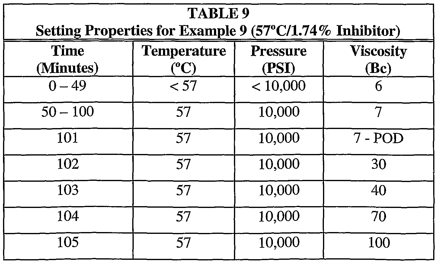
- Tables 4-11 provide select data points. Again, “POD” refers to the point of departure at which the sample compositions began to undergo the phase transition reaction.
- Example 4 A specimen according to the base formulation was prepared. The specimen composition included three grams (0.86 weight % of the MgO) of R-Tek inhibitor (sodium hexametaphosphate). The specimen was heated in the consistometer to a temperature of 65°C with a 50 minute ramp. Pressure was set to 10,000 psi. Figure 4 provides the temperature, pressure and viscosity data while Table 4 provides select data points relating to the phase transition reaction.
- Example 4 shows that the composition began to undergo the phase transition from flowable slurry to solid (i.e., the POD) at about 57 minutes.
- the composition set to form a solid at 60 minutes.
- the temperature of the composition was observed to be between about 60-68°C at this time.
- the data, and the corresponding graph ( Figure 4), demonstrate that the phase transition is sudden at an approximate composition temperature of about 60- 68°C.
- the shape of the curve in Figure 4 is indicative of the right-angle set characteristic of compositions of the invention.
- Figure 15 presents compressive strength data for a composition according to Example 4.
- the data were generated by a Chandler pressurised, ultrasonic compressive strength tester programmed, as in Example 4, to heat the specimen to a temperature of 65°C with a 50 minute ramp with pressure set to ramp to 10,000 psi.
- the data show that the composition achieved a compressive strength of about 1250 psi within 43 minutes following the POD (which occurred at 57 minutes) and that the compressive strength is increasing rapidly at that time.
- An important aspect of the invention is the rapid increase in compressive strength. As shown in Figure 15, the compressive strength increased almost 1175 psi in the 40 minutes following the POD. This very rapid increase in compressive strength makes the composition particularly useful in sealing pressurised formations.
- Example 5 A second specimen according to the base formulation was prepared to evaluate the effect of increasing the weight percentage of inhibitor in the composition.
- Example 5 differed from Example 4 in that six grams (1.76 weight % of the MgO) of R-Tek were included in the composition. The specimen was heated to a temperature of 65°C over a 50 minute time ramp. Pressure was set to linearly increase to 10,000 psi over 50 minutes.
- Figure 5 and Table 5 provide the temperature, pressure and viscosity measurements for the example.
- Example 5 demonstrates the same phase transition and right-angle set as the composition of Example 4 except that the phase transition occurs about 16 minutes later than does the phase transition in Example 4.
- the composition temperature was observed to be 60-68°C at POD. The difference in timing ofthe phase transition is explained by the greater concentration of inhibitor present in the composition of Example 5.
- Example 6 A third specimen according to the base formulation was prepared to evaluate the effect of further increasing the weight percentage of inhibitor in the composition.
- the composition of Example 6 differed from the compositions of Examples 4 and 5 in that twelve grams (3.48 weight % of the MgO) of R-Tek were added to the composition.
- the specimen was heated to a temperature of 65°C with a 50 minute ramp up.
- Consistometer pressure was set to 10,000 psi.
- Figure 6 and Table 6 provide the temperature, pressure and viscosity data for the sample run.
- Example 6 demonstrates that the composition began to undergo the phase transition at about 108 minutes.
- the composition was essentially solid at 111 minutes.
- the data in Table 6 and Figure 6 demonstrate that the phase transition of the composition is rapid.
- the phase transition again occurred at an observed composition temperature of about 60-68°C.
- the shape of the curve in Figure 6 is indicative of the right-angle set characteristic of compositions of the invention.
- the phase transition delay is again due to the increased concentration of the inhibitor versus that in the compositions of Examples 4 and 5.
- Example 7 The purpose of Example 7 was to evaluate the effect of increased temperature on the phase transition properties of the composition of Example 6.
- a specimen was formulated in the same manner as the specimen of Example 6 including the addition of twelve grams (3.48 weight % of the MgO) of R-Tek. Unlike Example 6, the specimen was heated to a temperature of 80°C over a 50 minute ramp time. Consistometer pressure was set to increase to 10,000 psi over the 50 minute ramp. The temperature, pressure and viscosity data for the sample run are presented in Figure 7 and Table 7.
- Example 7 demonstrates that the phase transition occurs more rapidly at higher ambient temperatures.
- the phase transition of Example 7 began to occur 30 minutes earlier than the phase transition of Example 6.
- the observed composition temperature at 78 minutes was between about 60-68°C.
- the surrounding temperature therefore, affects the rate at which the composition reaches the approximate 60-68°C composition temperature required for the phase transition to occur.
- the phase transition occurs more rapidly at elevated temperatures.
- the right-angle set is seen in Figure 7.
- Example 8 includes an evaluation of a composition according to Example 5, but heated to a slightly greater temperature.
- the specimen of Example 8 was prepared according to the base formulation of the invention.
- six grams (1.74 weight % of the MgO) of R-Tek were included in the composition.
- the oil bath was heated to a temperature of 73°C with a 50 minute time ramp.
- Consistometer pressure was set to 10,000 psi. Temperature, pressure and viscosity data are presented in Figure 8 and Table 8.
- Example 8 demonstrates that the composition began to undergo the phase transition at about 67 minutes.
- the composition formed a solid at about 69 minutes.
- the characteristic right-angle set is again evident in Figure 8.
- the observed composition temperature at 67-69 minutes was between about 60-68°C.
- less time was required for the composition to set because of the elevated oil bath temperature versus that in Example 5.
- the data in Table 8 and Figure 8 demonstrate that the phase transition of the composition is rapid and again occurs at an approximate observed composition temperature of about 60-68°C.
- Example 9 was conducted to evaluate the effect of reduced temperature on the set time of a composition having the same inhibitor concentration as in Examples 5 and 8.
- a specimen was prepared in the same manner as in Examples 5 and 8. Again, six grams (1.74 weight % of the MgO) of R-Tek were included in the formulation.
- the oil bath containing the specimen was heated to a temperature of only 57°C with a 50 minute ramp up. Consistometer pressure was set at 10,000 psi. Table 9 and Figure 9 provide the temperature, pressure and viscosity measurements for the sample run.
- Example 10 In Example 10 the effect of increased temperature and increased inhibitor concentration was evaluated. A specimen according to the base formulation was again prepared. Five percent by weight of the MgO of R- Tek inhibitor were included in the composition, i this example, the oil bath and specimen were heated to a temperature of 80°C with a 50 minute time ramp. Example 10 is the essentially the same test as that in Example 7 but with an additional 1.26% inhibitor. Consistometer pressure was set to 10,000 psi. Table 10 and Figure 10 provide the oil bath temperature, pressure and composition viscosity data for the sample run.
- Example 11 was prepared to evaluate the effect of a decreased temperature on the phase transition properties of a composition like that of Example 6. Again, a specimen was prepared according to the base formulation. As in Example 6, twelve grams (3.48 weight % of the MgO) of R-Tek were added to the composition. The specimen was heated to a temperature of 55 °C (10 °C less than in Example 6) with a 50 minute time ramp. Figure 11 provides the oil bath temperature, pressure and composition viscosity data for the sample run while Table 11 provides select data points.
- Example 6 As expected, a greater amount of time, 148 minutes, was required for the composition to reach the POD versus that of Example 6 which required only 108 minutes to reach the POD.
- the composition temperature at 148 minutes was observed to be about 60-68°C.
- the 40 minute time difference in reaching the POD may be explained by the lower oil bath temperature provided in Example 11 which increases the amount of time required for the exothermic reaction to heat the composition to the temperature required for the phase transition to occur.
- the right-angle set is again evident in Figure 11 despite the fact that more time was required for the set to occur.
- Figure 12 The solid line in Figure 12 is identified as "data set #1" and is based on the setting properties data of Tables 4-6 and Figures 4-6.
- the setting properties of the compositions of Examples 4-6 were also obtained at an earlier time under the same conditions and protocol to those in Examples 4-6. That information is identified as "data set #2" and is represented by the dashed line in Figure 12.
- the near-identical nature of the data in data sets 1 and 2 in Figure 12 show that the composition has consistent setting properties.
- the data of Figure 12 also show a near-linear relationship between the time required for each exemplary composition to reach 100 B c at varying inhibitor concentrations when the temperature is held constant. These data demonstrate that the phase transition and right-angle set occur in a predictable manner at varying inhibitor concentrations.
- the data points need not be completely linear but must not reflect an exponential relationship between the time needed for the reaction and the inhibitor concentration at the selected temperature.
- Figure 13 is a graph showing the setting times required for the compositions of Examples 6, 7 and 11 to reach a viscosity of 100 B 0 .
- the compositions of Examples 6, 7 and 11 each included identical inhibitor concentrations (3.48 wt.% ofthe MgO) but were heated by the consistometer to temperatures of 65, 80 and 55 °C respectively.
- the right-most data set represents the total amount of time required for each composition to reach a viscosity of 100 B c including the 50 minute ramp to the respective final temperature.
- the left-most data set represents the total amount of time that each composition was held at the respective final temperature before reaching a viscosity of 100 B c . This data set excludes the 50 minutes required to reach the final temperature.
- Figures 12 and 13 show that the set time is predictably extended by increasing the inhibitor concentration and/or decreasing the ambient temperature. Importantly, the data show that the set time can be determined based on the ambient temperature and/or inhibitor concentration thereby providing operators of down hole wellbore operations with a previously unknown degree of control over the cement.
- Examples 12-13 further demonstrate that the inventive Thermatek compositions, including other additives like viscosity modifiers, inhibitors and weighting agents, undergo a predictable phase transition from a flowable slurry to a solid state at varying temperatures and inhibitor concentrations.
- the data demonstrate that the compositions set predictably in the presence of contaminants typically encountered in actual drilling operations.
- Example 12 is the Thermatek base composition.
- Example 13 is the Thermatek base formulation together with a weighting agent as described below.
- the base formulation comprising Example 12 and used for Example 13 comprised an unweighted slurry prepared according to the following mixing order:
- Thermatek magnesium oxide powder and the dolomite powder were blended in the approximate 4.1:1 ratio set forth in the base formulation mixing
- Thermatek magnesium oxide powder and the dolomite powder were blended in the approximate 4.1:1 ratio set forth in the base formulation mixing order table.
- the dolomite is not a required constituent of the invention.
- a brine solution consisting of fresh water and C-Tek magnesium chloride salt was prepared by admixing 204g of the magnesium chloride salt with 204mL fresh water for approximately 2 minutes. The admixing was discontinued when the salt was observed to be in solution.
- magnesium oxide/dolomite powder blend was admixed with the brine for approximately 2 minutes to form the base formulation slurry.
- the magnesium oxide powder used in Examples 12-13 had a median particle size distribution, by volume, of about 2-8 ⁇ .
- the slurry was observed to be flowable with a fluid density of about 13.6 P.G. (1.63 SG).
- Example 13 consisted ofthe base formulation and a barite weighting agent provided to increase the mass and density of the composition.
- a weighting agent such as barite
- the following table shows the mixing order of the slurry including the weighting agent.
- Example 12 unweighted Thermatek slurry
- Example 13 weighted base formulation slurry
- Example 12 The unweighted Thermatek slurry composition of Example 12 was subjected to the static setting time tests at 100°F (38°C), 150°F (66°C) and 200P (93°C) all at ambient pressure. After the rheological properties were dete ⁇ nined, as reported in Table 12 above, the samples of the unweighted slurry samples were placed in three different ovens.
- Example 13 The weighted Thermatek slurry sample of Example 13 was placed in an oven at 150°F (66°C) at ambient pressure. The setting time of the weighted slurry was determined as set forth in Table 16.
- the unweighted and weighted Thermatek slurry compositions of Examples 12 and 13 were next exposed to three different contaminant fluids typical of contaminants found in drilling operations.
- the purpose of the experiments was to evaluate the effect of the contaminants on the setting properties of both exemplary compositions.
- the contaminants used in Examples 14-15 consisted of one of: (1) seawater, (2) NOVATEC brand invert emulsion field mud and (3) laboratory prepared KCl/Glycol water-based mud with 35 ppb KC1 and 4% by volume Glycol at 12.5ppg (1.5SG). The rheological properties of the three contaminants were taken using a Fann Drilling Fluid Viscometer and are presented in Table 17.
- each of the contaminant fluids was added to separate samples of the unweighted Thermatek slurry of Example 12 and weighted Thermatek slurry of Example 13 at 0.25 bbl equivalents of contaminant to 0.75 bbl equivalent of the slurry.
- Rheological properties of the composition of Example 14 (unweighted slurry and contaminants) and Example 15 (weighted slurry and contaminants) were determined using a Fann Drilling Fluid Viscometer prior to static setting time testing. The properties were as reported in Tables 18 and 19 below.
- Example 14 Samples of each unweighted, Thermatek slurry sample of Example 12, with the respective contaminant, were placed in ovens at 150°F (66°C). The setting time of each contaminated slurry was determined as set forth in Tables 20-22.
- Example 15 Samples of each weighted, Thermatek slurry sample of Example 13, with the respective contaminant, were placed in ovens at 150°F (66°C). The setting time of each contaminated slurry was determined as set forth in Tables 23-25. Although the rheological properties of the contaminated and weighted Thermatek slurry samples were elevated, the fluids all appeared to retain their pumpability.
- the data show that contamination does not adversely affect the phase transition of the weighted Thermatek slurry.
- the set times of the contaminated, weighted slurries were similar. Such set times were also comparable to the set time of the uncontaminated weighted slurry as shown in Table 16.
- Examples 16-17 R-Tek inhibitor was added to the unweighted and weighted Thermatek slurry compositions of Examples 12 and 13 to evaluate the effect of the inhibitor on the setting properties of the compositions.
- the inhibitor was admixed with the fresh water before addition of the other constituents. 11.94g of inhibitor (5% by weight of inhibitor based solely on the magnesium oxide) was added to each of the exemplary compositions.
- the rheological properties of Examples 16 and 17 were determined using a Fann Drilling Fluid Viscometer as set forth in Table 26 prior to static setting time testing.
- Example 16-17 The compositions of Examples 16-17 were placed in an oven at 150°F (66°C) under static conditions and ambient pressure. There was no attempt to provide a linear temperature/pressure ramp as in Examples 1-11. Viscosity observations were made every 30 minutes for three hours. Observations for the unweighted slurry with inhibitor (Example 16) and the weighted slurry with inhibitor (Example 17) are presented in Tables 27 and 28 respectively.
- Example 18 Acid Solubility
- Acid solubility is an important requirement for wellbore compositions of the invention because an acid solvent may be used to remove the hardened composition from the wellbore. The ability to remove the composition from the well bore provides a greater degree of control over the drilling operation.
- a one-half inch cube sample of the cured composition according to Example 12 was obtained.
- the cube was placed in a container with 100 mL of a solution of aqueous 15 % hydrochloric acid (HCl). Observations were made with respect to the solubilization of the cube. After 30 to 40 minutes, the cube was observed to be solubilized with only a trace amount of insoluble debris present in the beaker.
- the solid state form ofthe inventive composition is almost totally soluble in 15% HCl solution.
- Example 19 Non-invasiveness Compositions of the invention were evaluated for their noninvasive properties with respect to geological formations surrounding the wellbore.
- Noninvasiveness is an important property of the invention because filtrate and composition flow into surrounding earthen formations can be limited thereby minimizing potential damage to the reservoirs and surrounding earthen formations.
- the noninvasive nature of the composition is also desirable because that property facilitates removal of the hardened composition from the well bore because the composition can be contacted and solubilized by an acid solution.
- Core permeability tests were performed in order to determine the non- invasiveness of the compositions. The purpose of the experiments was to compare the permeability of the cores after placement of the composition within the cores against the return permeability of the cores after solubilization and removal of the hardened composition. The extent to which core permeability is restored is a measure of the extent to which the composition is non-invasive. A composition which significantly invades the surrounding formation will not be accessible to, or removable by, an acid solvent and is, therefore, considered invasive.
- Example 19 simulate placement of the composition into a wellbore shaft.
- Three inch deep Berea sandstone cores of 100 and 300 md (air permeability) were selected for the experiment.
- a 4 % ammonium chloride solution was selected as a reference brine for determination of initial and final permeability of cores.
- the flow rate of the reference brine through the three cores is provided in Table 29.
- a Thermatek base formulation according to Example 12 was prepared. The slurry was injected into each core at 4000 psi differential pressure at 60°C. The Thermatek was allowed to harden. The 4% ammonium chloride solution was then injected into the cores following hardening of the Thermatek and the flow rate recorded. A 15% aqueous HCl solution was next injected into the cores to solubilize the Thermatek. Subsequently, the reference brine was injected into the cores and the flow rate was again determined and recorded.
- the data show that the hardened form of the composition sealed the cores and blocked essentially all flow of the reference brine through the cores. After an aqueous 15% HCl solution was injected into the cores the flow rate of the reference brine was fully restored. These data demonstrate that the hardened form of the composition is not invasive because the composition did not significantly flow into the porous sandstone material surrounding the cores thereby permitting the composition to be solubilized and removed from the cores. These data further demonstrate that the composition is essentially 100% soluble in an aqueous 15% HCl solution.
- Examples 20-21 Base Slurry Density Reduction by Dilution Examples 20 and 21, exemplary compositions of the invention were diluted with fresh water and seawater. The setting properties of the diluted compositions were then observed.
- Thermatek base slurry was prepared according to the following mixing order:
- Thermatek base composition was scaled-up to make a four barrel equivalent batch of the composition of Example 20.
- the base slurry had a density of 13.6 ppg (1.63 SG).
- Example 20 three fresh water slurry dilutions were prepared with densities of 12.5 ppg (1.50 SG), 11.5 ppg (1.38 SG) and 10.5 ppg (1.26 SG). V-Tek viscosity modifier was added to each slurry as a strengthening agent and to limit any separation of the slurry constituents. The cut-backs were calculated as follows:
- the three fresh water cut-back samples shown in Table 30 were placed in a static oven at 150°F (66°C) and ambient pressure.
- the time required for a hard set for the 12.5 ppg dilution was 105 minutes and for the 11.5 ppg dilution was 135 minutes.
- Example 21 With respect to the 10.5 ppg dilution, that sample exhibited approximately 10% free water separation on the surface after 45 minutes in the oven. After 180 minutes, about 5% of the free water had evaporated but the sample was not set hard. The 10.5 ppg dilution sample was left in the oven for 16 hours. The free water had evaporated but the sample was only slightly harder than it was at 180 minutes.
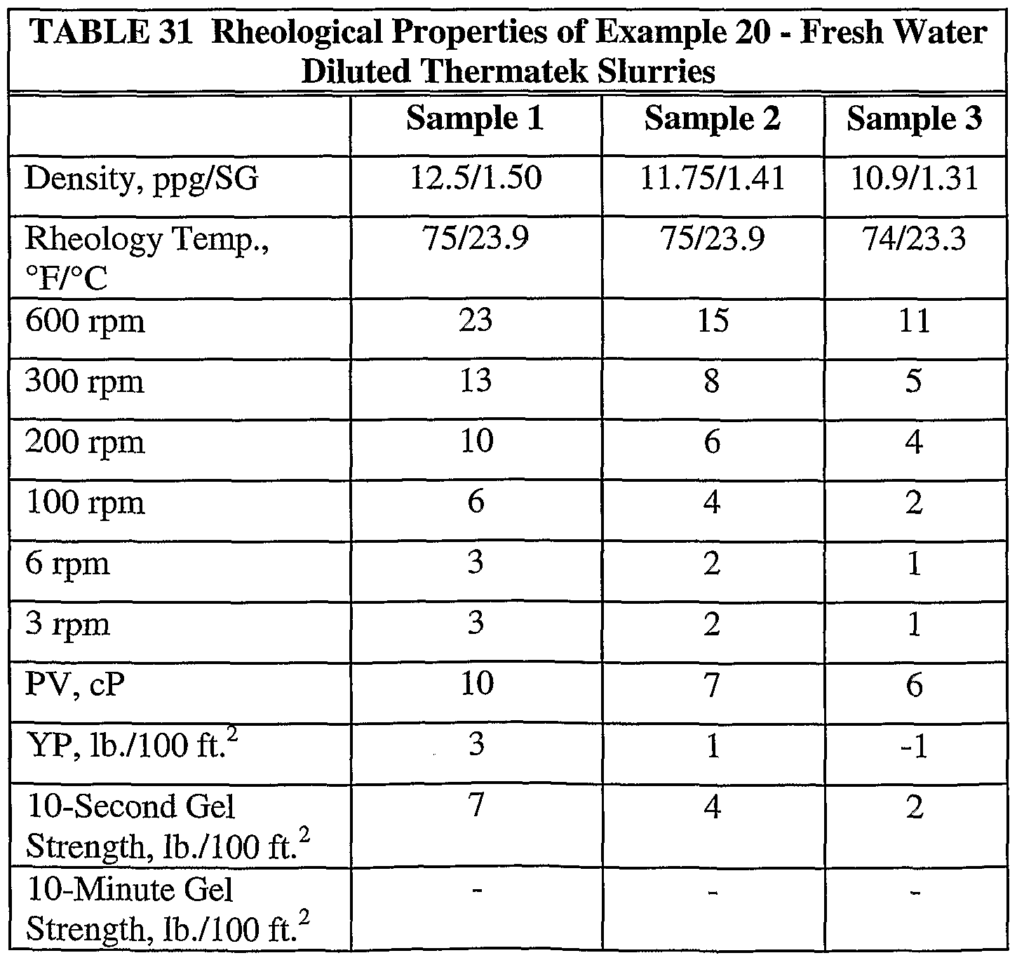
- a new batch of the exemplary base composition was scaled-up to make a fresh four barrel equivalent batch of the composition. The base slurry again had a density of 13.6 ppg (1.63 SG). The composition was diluted with environmental seawater as set forth in Table 32. V-Tek was added to the three dilutions as shown in Table 31. The V-Tek was provided as a strengthening agent and in a sufficient amount to limit any separation of the constituents.
- the three dilution samples of Example 21 were as follows:
- Static setting time results for the three seawater diluted samples were similar to those of the three fresh-water-diluted samples.
- the 12.5 ppg dilution of Example 21 was hard set in 105 minutes while the 11.5 ppg dilution of Example 21 was hard set in 135 minutes.
- that sample exhibited approximately 10% free water separation on the surface after 45 minutes in the oven.
- the free water had evaporated to about 5% and the sample was very firm but not set hard.
- the 10.5 ppg dilution was slightly firmer, but still not set hard. A spatula could be inserted to the bottom of the sample with some force.
- the sample was crumbly, chalky and tacky with a consistency similar to a bar of bath soap.
- Examples 20 and 21 show that the compositions of the invention can be prepared in a broad range of dilutions.
- the inventive magnesium oxychloride can be present in an amount greater than about 30% to about 70% of the composition.
- a preferred range for the magnesium oxychloride is between about 40-70%.
- the composition will form a solid-state material when diluted with either fresh water or environmental sea water.
- Example 22 is an evaluation of Baymag 96-200 MgO showing the same set characteristics but at a higher temperature and using a different MgO but otherwise with the same base formulation as described in example 11 above.
- Phase transition normally occurred more rapidly at the higher ambient temperatures.
- the phase transition of the composition in Example 22 began to occur at 57 minutes.
- the observed composition temperature at 57 minutes was between about 130-134°C.
- the surrounding temperature therefore, affected the rate at which the composition reached the approximate 134°C composition temperature required for the phase transition to occur.
- the phase transition occurs more rapidly at elevated temperatures.
- the flat , viscosity profile remains the same with the attendant right angle set at the phase transition.
- the right-angle set is seen in Figure 17.
- Example 10 includes an evaluation of a composition according to Example 22, but heated to a slightly lower temperature.
- the specimen of Example 23 was prepared according to the base formulation of the invention but replacing the MgO with Baymag -96/200. Because of the lower temperature the R-Tek inhibitor was reduced to 8.2 grams, or 2%, in the composition.
- the oil bath was heated to a temperature of 110°C with a 30 minute time ramp. Consistometer pressure was set to 10,000 psi. Temperature, pressure and viscosity data are presented in Figure 18 and Table 35 below.
- Example 23 demonstrates that the composition began to undergo the phase transition at about 58 minutes.
- the composition formed a solid at about 59 minutes.
- the characteristic right-angle set is again evident in Figure 18.
- the observed composition temperature at 57-59 minutes was about 110°C.
- more time was required for the composition to set because of the lowered oil bath temperature versus that in Example 22.
- the data in table 35 and Figure 18 demonstrate that the phase transition of the composition is the same as in table 34, and occurs at an approximate observed composition temperature of about 110°C.
- the relationship between the temperature /time and inhibitor is linear demonstrating the predictability (and therefore the controllability) of the composition at differing temperatures.
- Example 24 is an evaluation of Lycal 93/12F MgO at a lower temperature of 29oC as compared with the temperatures used in previous examples. Because of the lower temperature the exothermic reaction to reach the POD is slower.
- the graph in Fig 19 shows a gradual increase in pumpable viscosity up to the POD which is almost instantaneous, with the set showing an absolute right angle.
- the formulation content ratios are the same for all the tests at high, medium and low temperatures, showing the same set characteristics at greatly lowered temperatures, as per the previously documented higher temperature data using different MgOs but otherwise with the same base formulation. Phase transition normally occurs more slowly at lower ambient temperatures. The phase transition of Example 24 began to occur at 67 minutes. The observed composition temperature at 67 minutes was 29°C.
- Example 25 employs the same composition as example 24, shown in table 36 but substituting Lycal 93/12F for Baymag/40.
- the consistometer results are shown in Fig 20.
- the final POD is the same.
- the viscosity profile prior to POD has a much lower and flatter profile.
- the POD is extremely rapid.
- the characteristic right-angle set is again evident in Fig 20.
- the required composition temperature of 29 OC was ramped over 15 minutes.
- the composition temperature remained at 29 OC for 63 minutes until the POD. This was 10 minutes longer than the total time taken to POD by the Lycal 93/12F MgO.
- compositions are useful in treating wellbores in order to seal them as described herein, but certain embodiments may also find use in methods of treating wells for squeezing compositions into the formation in order to affect the formation outwith the wellbore itself.
- the composition can bond to sandy or shale formations to consolidate them, to seal off faults or fissures in the formation, or to isolate one zone of the formation from another, which can optionally be carried out in the absence of remedial operations to correct an apparent deficiency in the formation being treated.
- the composition can also be used to seal faults or fissures in the formation outwith the wellbore. It should be understood that the composition may be used in applications other than hydrocarbon drilling operations.
- the composition can be used in any drilling operation where control over underground substances, such as fluids, gases and particulates, is desired.
- the composition may also be used in applications in addition to those involving the sealing of wellbores.
- Such uses include remedial and work over operations — operations in which the acid solubility and non-invasiveness of the composition would be particularly useful properties.
Abstract
Description


Claims
Priority Applications (5)
| Application Number | Priority Date | Filing Date | Title |
|---|---|---|---|
| EA200201266A EA008274B1 (en) | 2000-06-06 | 2001-06-05 | Composition for controlling wellbore fluid and gas invasion and method for using same |
| AU2001262511A AU2001262511A1 (en) | 2000-06-06 | 2001-06-05 | Composition for controlling wellbore fluid and gas invasion and method for usingsame |
| EP01936641A EP1292756A2 (en) | 2000-06-06 | 2001-06-05 | Composition for controlling wellbore fluid and gas invasion and method for using same |
| US10/297,752 US7044222B2 (en) | 2000-06-06 | 2001-06-05 | Composition for controlling wellbore fluid and gas invasion and method for using same |
| NO20025890A NO324366B1 (en) | 2000-06-06 | 2002-12-06 | Composition for control of well fluid and gas penetration and method for using the same |
Applications Claiming Priority (2)
| Application Number | Priority Date | Filing Date | Title |
|---|---|---|---|
| US09/588,422 US6664215B1 (en) | 2000-06-06 | 2000-06-06 | Composition for controlling wellbore fluid and gas invasion and method for using same |
| US09/588,422 | 2000-06-06 |
Publications (2)
| Publication Number | Publication Date |
|---|---|
| WO2001093842A2 true WO2001093842A2 (en) | 2001-12-13 |
| WO2001093842A3 WO2001093842A3 (en) | 2002-03-28 |
Family
ID=24353774
Family Applications (1)
| Application Number | Title | Priority Date | Filing Date |
|---|---|---|---|
| PCT/GB2001/002471 WO2001093842A2 (en) | 2000-06-06 | 2001-06-05 | Composition for controlling wellbore fluid and gas invasion and method for using same |
Country Status (6)
| Country | Link |
|---|---|
| US (2) | US6664215B1 (en) |
| EP (1) | EP1292756A2 (en) |
| AU (1) | AU2001262511A1 (en) |
| EA (1) | EA008274B1 (en) |
| NO (1) | NO324366B1 (en) |
| WO (1) | WO2001093842A2 (en) |
Cited By (7)
| Publication number | Priority date | Publication date | Assignee | Title |
|---|---|---|---|---|
| US6664215B1 (en) | 2000-06-06 | 2003-12-16 | Brian H. Tomlinson | Composition for controlling wellbore fluid and gas invasion and method for using same |
| US7246665B2 (en) | 2004-05-03 | 2007-07-24 | Halliburton Energy Services, Inc. | Methods of using settable compositions in a subterranean formation |
| US7350576B2 (en) | 2005-08-17 | 2008-04-01 | Halliburton Energy Services, Inc. | Methods of sealing subterranean formations using rapid setting plugging compositions |
| US7544641B2 (en) | 2005-08-17 | 2009-06-09 | Halliburton Energy Services, Inc. | Rapid setting plugging compositions for sealing subterranean formations |
| CN102516962A (en) * | 2011-11-24 | 2012-06-27 | 中国科学院青海盐湖研究所 | Hole sealing material of potassium-magnesium salt mine drilling holes and hole sealing method thereof |
| US9546313B2 (en) | 2013-12-13 | 2017-01-17 | Brian Henry Tomlinson | Compositions and methods for controlling wellsite fluid and gas flow |
| WO2019122858A1 (en) * | 2017-12-20 | 2019-06-27 | Ardyne Holdings Limited | Improvements in or relating to well abandonment and slot recovery |
Families Citing this family (74)
| Publication number | Priority date | Publication date | Assignee | Title |
|---|---|---|---|---|
| US6951250B2 (en) | 2003-05-13 | 2005-10-04 | Halliburton Energy Services, Inc. | Sealant compositions and methods of using the same to isolate a subterranean zone from a disposal well |
| US7527098B2 (en) * | 2004-05-27 | 2009-05-05 | Halliburton Energy Services, Inc. | Methods of increasing the thickening times of phosphate-based cementitious compositions in high-temperature wellbores |
| US8703659B2 (en) * | 2005-01-24 | 2014-04-22 | Halliburton Energy Services, Inc. | Sealant composition comprising a gel system and a reduced amount of cement for a permeable zone downhole |
| WO2007014168A2 (en) * | 2005-07-25 | 2007-02-01 | Dennis Andrew C | Magnesium cementitious composition |
| CA2618150C (en) | 2005-08-17 | 2010-11-30 | Halliburton Energy Services, Inc. | Rapid setting plugging compositions and methods for sealing subterranean formations |
| US8297357B2 (en) | 2005-09-09 | 2012-10-30 | Halliburton Energy Services Inc. | Acid-soluble cement compositions comprising cement kiln dust and/or a natural pozzolan and methods of use |
| US9023150B2 (en) | 2005-09-09 | 2015-05-05 | Halliburton Energy Services, Inc. | Acid-soluble cement compositions comprising cement kiln dust and/or a natural pozzolan and methods of use |
| US8950486B2 (en) | 2005-09-09 | 2015-02-10 | Halliburton Energy Services, Inc. | Acid-soluble cement compositions comprising cement kiln dust and methods of use |
| WO2007035707A2 (en) * | 2005-09-16 | 2007-03-29 | Saudi Arabian Oil Company | Well cement formulations for increased drilling hardness |
| US7694738B2 (en) * | 2005-12-01 | 2010-04-13 | Halliburton Energy Services, Inc. | Methods of using wellbore sealant compositions containing cationic latexes |
| US7687440B2 (en) * | 2005-12-01 | 2010-03-30 | Halliburton Energy Services, Inc. | Wellbore sealant compositions containing cationic latexes |
| US20070130608A1 (en) * | 2005-12-05 | 2007-06-07 | Samsung Electronics Co., Ltd. | Method and apparatus for overlaying broadcast video with application graphic in DTV |
| US7776797B2 (en) | 2006-01-23 | 2010-08-17 | Halliburton Energy Services, Inc. | Lost circulation compositions |
| US8132623B2 (en) | 2006-01-23 | 2012-03-13 | Halliburton Energy Services Inc. | Methods of using lost circulation compositions |
| US7530394B2 (en) * | 2006-06-30 | 2009-05-12 | Halliburton Energy Services, Inc. | Cement compositions for low temperature applications |
| US20080060811A1 (en) * | 2006-09-13 | 2008-03-13 | Halliburton Energy Services, Inc. | Method to control the physical interface between two or more fluids |
| US7789149B2 (en) * | 2006-11-03 | 2010-09-07 | Halliburton Energy Services, Inc. | Methods of servicing wellbore with composition comprising ultra low density thermatek® slurries |
| US7431086B2 (en) * | 2007-01-11 | 2008-10-07 | Halliburton Energy Services, Inc. | Methods of servicing a wellbore with compositions comprising quaternary material and sorel cements |
| US7763572B2 (en) * | 2007-01-11 | 2010-07-27 | Halliburton Energy Services, Inc. | Compositions comprising quaternary material and sorel cements |
| US7893011B2 (en) * | 2007-01-11 | 2011-02-22 | Halliburton Energy Services Inc. | Compositions comprising Sorel cements and oil based fluids |
| US7350575B1 (en) | 2007-01-11 | 2008-04-01 | Halliburton Energy Services, Inc. | Methods of servicing a wellbore with compositions comprising Sorel cements and oil based fluids |
| US8302686B2 (en) * | 2007-04-02 | 2012-11-06 | Halliburton Energy Services Inc. | Use of micro-electro-mechanical systems (MEMS) in well treatments |
| US7712527B2 (en) | 2007-04-02 | 2010-05-11 | Halliburton Energy Services, Inc. | Use of micro-electro-mechanical systems (MEMS) in well treatments |
| US9200500B2 (en) | 2007-04-02 | 2015-12-01 | Halliburton Energy Services, Inc. | Use of sensors coated with elastomer for subterranean operations |
| US9732584B2 (en) * | 2007-04-02 | 2017-08-15 | Halliburton Energy Services, Inc. | Use of micro-electro-mechanical systems (MEMS) in well treatments |
| US8083849B2 (en) | 2007-04-02 | 2011-12-27 | Halliburton Energy Services, Inc. | Activating compositions in subterranean zones |
| US10358914B2 (en) | 2007-04-02 | 2019-07-23 | Halliburton Energy Services, Inc. | Methods and systems for detecting RFID tags in a borehole environment |
| US8316936B2 (en) | 2007-04-02 | 2012-11-27 | Halliburton Energy Services Inc. | Use of micro-electro-mechanical systems (MEMS) in well treatments |
| US8297353B2 (en) * | 2007-04-02 | 2012-10-30 | Halliburton Energy Services, Inc. | Use of micro-electro-mechanical systems (MEMS) in well treatments |
| US8297352B2 (en) * | 2007-04-02 | 2012-10-30 | Halliburton Energy Services, Inc. | Use of micro-electro-mechanical systems (MEMS) in well treatments |
| US9394756B2 (en) | 2007-04-02 | 2016-07-19 | Halliburton Energy Services, Inc. | Timeline from slumber to collection of RFID tags in a well environment |
| US9394784B2 (en) | 2007-04-02 | 2016-07-19 | Halliburton Energy Services, Inc. | Algorithm for zonal fault detection in a well environment |
| US8162050B2 (en) * | 2007-04-02 | 2012-04-24 | Halliburton Energy Services Inc. | Use of micro-electro-mechanical systems (MEMS) in well treatments |
| US20110187556A1 (en) * | 2007-04-02 | 2011-08-04 | Halliburton Energy Services, Inc. | Use of Micro-Electro-Mechanical Systems (MEMS) in Well Treatments |
| US9394785B2 (en) | 2007-04-02 | 2016-07-19 | Halliburton Energy Services, Inc. | Methods and apparatus for evaluating downhole conditions through RFID sensing |
| US9194207B2 (en) | 2007-04-02 | 2015-11-24 | Halliburton Energy Services, Inc. | Surface wellbore operating equipment utilizing MEMS sensors |
| US8291975B2 (en) * | 2007-04-02 | 2012-10-23 | Halliburton Energy Services Inc. | Use of micro-electro-mechanical systems (MEMS) in well treatments |
| US9494032B2 (en) | 2007-04-02 | 2016-11-15 | Halliburton Energy Services, Inc. | Methods and apparatus for evaluating downhole conditions with RFID MEMS sensors |
| US9822631B2 (en) | 2007-04-02 | 2017-11-21 | Halliburton Energy Services, Inc. | Monitoring downhole parameters using MEMS |
| US8342242B2 (en) | 2007-04-02 | 2013-01-01 | Halliburton Energy Services, Inc. | Use of micro-electro-mechanical systems MEMS in well treatments |
| US8162055B2 (en) | 2007-04-02 | 2012-04-24 | Halliburton Energy Services Inc. | Methods of activating compositions in subterranean zones |
| US8586508B2 (en) * | 2007-05-30 | 2013-11-19 | Halliburton Energy Services, Inc. | Polysaccharide based cement additives |
| US8569214B2 (en) | 2007-05-30 | 2013-10-29 | Halliburton Energy Services, Inc. | Methods of using polysaccharide based cement additives |
| EP2085449A1 (en) * | 2007-12-28 | 2009-08-05 | Services Pétroliers Schlumberger | Cement composition comprising mixture of organic and inorganic fibres for curing severe losses especially in the reservoir section |
| US7740070B2 (en) * | 2008-06-16 | 2010-06-22 | Halliburton Energy Services, Inc. | Wellbore servicing compositions comprising a density segregation inhibiting composite and methods of making and using same |
| US7654326B1 (en) * | 2008-07-10 | 2010-02-02 | Halliburton Energy Services, Inc. | Sorel cements and methods of making and using same |
| US7854262B2 (en) * | 2008-10-14 | 2010-12-21 | Halliburton Energy Services, Inc. | Sorel cement compositions, amine phosphono retarders, and associated methods |
| US20100212892A1 (en) * | 2009-02-26 | 2010-08-26 | Halliburton Energy Services, Inc. | Methods of formulating a cement composition |
| CA2768936A1 (en) * | 2009-07-31 | 2011-02-03 | Bp Corporation North America Inc. | Method to control driving fluid breakthrough during production of hydrocarbons from a subterranean reservoir |
| US8408303B2 (en) * | 2009-09-24 | 2013-04-02 | Halliburton Energy Services, Inc. | Compositions for improving thermal conductivity of cement systems |
| KR101731666B1 (en) * | 2010-01-14 | 2017-04-28 | 엔지니어드 어레스팅 시스템즈 코포레이션 | Cellular phosphate ceramics and methods of manufacture and use |
| US8418763B1 (en) | 2012-04-27 | 2013-04-16 | Halliburton Energy Services, Inc. | Self-degrading cement compositions and associated fluid loss applications |
| US9617460B2 (en) | 2012-09-18 | 2017-04-11 | Halliburton Energy Services, Inc. | Magnesium chloride in alcoholic solvent for sorel cement |
| US9133386B2 (en) | 2012-12-12 | 2015-09-15 | Hallburton Energy Services, Inc. | Viscous settable fluid for lost circulation in subterranean formations |
| US10081755B2 (en) | 2012-12-31 | 2018-09-25 | M-I Drilling Fluids Uk Ltd | Set on demand cement compositions for curing fluid loss |
| US20140209307A1 (en) | 2013-01-29 | 2014-07-31 | Halliburton Energy Services, Inc. | Wellbore Fluids Comprising Mineral Particles and Methods Relating Thereto |
| WO2014120385A1 (en) * | 2013-01-30 | 2014-08-07 | Halliburton Energy Services, Inc. | Methods for producing fluid migration resistant cement slurries |
| WO2014165314A2 (en) | 2013-04-02 | 2014-10-09 | Halliburton Energy Services, Inc. | Surface wellbore operating equipment utilizing mems sensors |
| US10066146B2 (en) | 2013-06-21 | 2018-09-04 | Halliburton Energy Services, Inc. | Wellbore servicing compositions and methods of making and using same |
| CA3033413C (en) | 2013-12-13 | 2020-10-06 | Pluto Ground Technologies Holding Inc. | Cement compositions and methods for controlling wellsite fluid and gas flow |
| US9771773B2 (en) | 2014-06-12 | 2017-09-26 | Halliburton Energy Services, Inc. | Diutan as a rheological modifier in sorel cements |
| BR112017016096A2 (en) | 2015-02-27 | 2018-04-03 | Halliburton Energy Services Inc | method for making measurements in a hole, communication set and system for use in a hole, and detection set. |
| MX2017010984A (en) | 2015-03-03 | 2017-10-18 | Halliburton Energy Services Inc | Multi-coil rfid sensor assembly. |
| US10329472B2 (en) | 2015-03-04 | 2019-06-25 | Halliburton Energy Services, Inc. | Wellbore additives that include liquid-infiltrated porous silica |
| CN108929099B (en) * | 2017-05-26 | 2021-03-09 | 中国石油天然气集团公司 | Acid-soluble cement slurry and preparation method and application thereof |
| CN111119747B (en) * | 2018-11-01 | 2021-08-13 | 中国石油化工股份有限公司 | Drilling string and drilling completion integrated method |
| US11230497B2 (en) | 2019-04-10 | 2022-01-25 | Saudi Arabian Oil Company | Cement additives |
| CN110333551B (en) * | 2019-07-26 | 2020-09-25 | 长江大学 | Dolostone reservoir prediction method and system based on well-seismic combination and storage medium |
| US11148977B2 (en) | 2019-10-04 | 2021-10-19 | Saudi Arabian Oil Company | Sorel cement composition and method to cure loss of circulation |
| US11091964B1 (en) * | 2020-03-26 | 2021-08-17 | Halliburton Energy Services, Inc. | Method to manage tandem single string reactive LCM pill applications |
| US11434410B2 (en) | 2020-07-07 | 2022-09-06 | Halliburton Energy Services, Inc. | Methods of making and using a wellbore servicing fluid for controlling losses in permeable zones |
| CN111689757A (en) * | 2020-07-10 | 2020-09-22 | 安徽友胜建材科技集团有限公司 | Light homogeneous fireproof heat-insulation board |
| US11542424B1 (en) | 2021-12-09 | 2023-01-03 | Halliburton Energy Services, Inc. | Wellbore servicing fluids and methods for controlling fluid losses in permeable zones |
| US11858039B2 (en) | 2022-01-13 | 2024-01-02 | Saudi Arabian Oil Company | Direct ink printing of multi-material composite structures |
Citations (4)
| Publication number | Priority date | Publication date | Assignee | Title |
|---|---|---|---|---|
| US1634505A (en) * | 1922-05-01 | 1927-07-05 | Cleveland Trust Co | Oxychloride cement and process of making same |
| EP0558232A1 (en) * | 1992-02-19 | 1993-09-01 | Halliburton Company | Well cement methods and compositions |
| US5281270A (en) * | 1992-02-19 | 1994-01-25 | Halliburton Company | Retarded acid soluble well cement compositions and methods |
| EP0582367A1 (en) * | 1992-07-31 | 1994-02-09 | Halliburton Company | Retarded acid soluble well cement compositions |
Family Cites Families (27)
| Publication number | Priority date | Publication date | Assignee | Title |
|---|---|---|---|---|
| US1019083A (en) | 1910-03-04 | 1912-03-05 | Joseph Simson | Method of manufacturing jointless facings of floors, walls, and the like. |
| US2351641A (en) | 1939-10-02 | 1944-06-20 | Minnesota Mining & Mfg | Cementitious material |
| SU68063A1 (en) * | 1943-02-23 | 1946-11-30 | В.Г. Шакиева | Hydraulic to throttle |
| US2543959A (en) | 1945-09-01 | 1951-03-06 | Fmc Corp | Magnesium oxychloride cement mix and method of making |
| US2939799A (en) | 1957-04-02 | 1960-06-07 | Fmc Corp | Magnesium oxychloride cements |
| US3320077A (en) | 1966-01-19 | 1967-05-16 | William L Prior | Inorganic plastic cements and process for the preparation thereof |
| DE2140618C2 (en) * | 1971-07-12 | 1982-08-19 | Oil Base Germany GmbH, 2000 Hamburg | Method of temporarily sealing borehole areas |
| US3963849A (en) | 1971-11-01 | 1976-06-15 | Thompson Chemicals, Inc. | Fireproof product using magnesium oxychloride cement |
| US3951885A (en) | 1971-11-01 | 1976-04-20 | Thompson Chemicals, Inc. | Method of making magnesium oxychloride cement cofoamed with synthetic resin |
| US3887009A (en) * | 1974-04-25 | 1975-06-03 | Oil Base | Drilling mud-cement compositions for well cementing operations |
| US4209339A (en) | 1978-06-05 | 1980-06-24 | Norcem A/S | Cement compositions |
| US4158570A (en) | 1978-08-28 | 1979-06-19 | Ppg Industries, Inc. | Preparing magnesium oxychloride and/or oxysulfate cements |
| US4352694A (en) | 1980-07-18 | 1982-10-05 | Norcem A.S. | Process of producing sorel cement |
| US4480693A (en) | 1983-12-23 | 1984-11-06 | Exxon Research & Engineering Co. | Fluid loss control in oil field cements |
| US5130184A (en) * | 1984-04-25 | 1992-07-14 | Pyrotite Corporation | Fire barrier coating and fire barrier plywood |
| US4886550A (en) | 1985-10-15 | 1989-12-12 | American Colloid Company | Flexible grout composition and method |
| SU1513126A1 (en) * | 1987-05-21 | 1989-10-07 | Институт горного дела им.А.А.Скочинского | Binder |
| US5110361A (en) | 1988-11-04 | 1992-05-05 | Cac, Inc. | Magnesium oxychloride cement compositions and methods for manufacture and use |
| US5004505A (en) | 1988-11-04 | 1991-04-02 | Cac, Inc. | Magnesium oxychloride cement compositions and methods for manufacture and use |
| SU1641981A1 (en) * | 1988-11-21 | 1991-04-15 | Донецкий Научно-Исследовательский Угольный Институт | Method of preparing a consolidating composition |
| US5039454A (en) | 1990-05-17 | 1991-08-13 | Policastro Peter P | Zinc-containing magnesium oxychloride cements providing fire resistance and an extended pot-life |
| RU2015155C1 (en) | 1991-11-15 | 1994-06-30 | Макеев Николай Михайлович | Liquid for strengthening of unstable rocks at hole drilling |
| US5228524A (en) | 1992-02-25 | 1993-07-20 | Baker Hughes Incorporated | Fluid system for controlling fluid losses during hydrocarbon recovery operations |
| US5504062A (en) | 1992-10-21 | 1996-04-02 | Baker Hughes Incorporated | Fluid system for controlling fluid losses during hydrocarbon recovery operations |
| RU2060360C1 (en) * | 1994-03-10 | 1996-05-20 | Пермский государственный научно-исследовательский и проектный институт нефтяной промышленности | Tamponage composition |
| US6664215B1 (en) | 2000-06-06 | 2003-12-16 | Brian H. Tomlinson | Composition for controlling wellbore fluid and gas invasion and method for using same |
| WO2002098100A1 (en) | 2001-05-31 | 2002-12-05 | Preventon Technologies Limited | Access control systems |
-
2000
- 2000-06-06 US US09/588,422 patent/US6664215B1/en not_active Expired - Lifetime
-
2001
- 2001-06-05 EA EA200201266A patent/EA008274B1/en not_active IP Right Cessation
- 2001-06-05 AU AU2001262511A patent/AU2001262511A1/en not_active Abandoned
- 2001-06-05 WO PCT/GB2001/002471 patent/WO2001093842A2/en active Application Filing
- 2001-06-05 EP EP01936641A patent/EP1292756A2/en not_active Ceased
- 2001-06-05 US US10/297,752 patent/US7044222B2/en not_active Expired - Lifetime
-
2002
- 2002-12-06 NO NO20025890A patent/NO324366B1/en not_active IP Right Cessation
Patent Citations (4)
| Publication number | Priority date | Publication date | Assignee | Title |
|---|---|---|---|---|
| US1634505A (en) * | 1922-05-01 | 1927-07-05 | Cleveland Trust Co | Oxychloride cement and process of making same |
| EP0558232A1 (en) * | 1992-02-19 | 1993-09-01 | Halliburton Company | Well cement methods and compositions |
| US5281270A (en) * | 1992-02-19 | 1994-01-25 | Halliburton Company | Retarded acid soluble well cement compositions and methods |
| EP0582367A1 (en) * | 1992-07-31 | 1994-02-09 | Halliburton Company | Retarded acid soluble well cement compositions |
Non-Patent Citations (1)
| Title |
|---|
| See also references of EP1292756A2 * |
Cited By (8)
| Publication number | Priority date | Publication date | Assignee | Title |
|---|---|---|---|---|
| US6664215B1 (en) | 2000-06-06 | 2003-12-16 | Brian H. Tomlinson | Composition for controlling wellbore fluid and gas invasion and method for using same |
| US7246665B2 (en) | 2004-05-03 | 2007-07-24 | Halliburton Energy Services, Inc. | Methods of using settable compositions in a subterranean formation |
| US7863226B2 (en) | 2004-05-03 | 2011-01-04 | Halliburton Energy Services Inc. | Methods of using settable compositions in a subterranean formation |
| US7350576B2 (en) | 2005-08-17 | 2008-04-01 | Halliburton Energy Services, Inc. | Methods of sealing subterranean formations using rapid setting plugging compositions |
| US7544641B2 (en) | 2005-08-17 | 2009-06-09 | Halliburton Energy Services, Inc. | Rapid setting plugging compositions for sealing subterranean formations |
| CN102516962A (en) * | 2011-11-24 | 2012-06-27 | 中国科学院青海盐湖研究所 | Hole sealing material of potassium-magnesium salt mine drilling holes and hole sealing method thereof |
| US9546313B2 (en) | 2013-12-13 | 2017-01-17 | Brian Henry Tomlinson | Compositions and methods for controlling wellsite fluid and gas flow |
| WO2019122858A1 (en) * | 2017-12-20 | 2019-06-27 | Ardyne Holdings Limited | Improvements in or relating to well abandonment and slot recovery |
Also Published As
| Publication number | Publication date |
|---|---|
| NO20025890D0 (en) | 2002-12-06 |
| EA200201266A1 (en) | 2003-06-26 |
| NO20025890L (en) | 2003-01-27 |
| WO2001093842A3 (en) | 2002-03-28 |
| EP1292756A2 (en) | 2003-03-19 |
| US6664215B1 (en) | 2003-12-16 |
| US7044222B2 (en) | 2006-05-16 |
| AU2001262511A1 (en) | 2001-12-17 |
| NO324366B1 (en) | 2007-10-01 |
| US20040040711A1 (en) | 2004-03-04 |
| EA008274B1 (en) | 2007-04-27 |
Similar Documents
| Publication | Publication Date | Title |
|---|---|---|
| US7044222B2 (en) | Composition for controlling wellbore fluid and gas invasion and method for using same | |
| EP0616660B1 (en) | Method of propagating a hydraulic fracture using fluid loss control particulates | |
| US6342467B1 (en) | Method and composition for controlling fluid loss in high permeability hydrocarbon bearing formations | |
| US7789149B2 (en) | Methods of servicing wellbore with composition comprising ultra low density thermatek® slurries | |
| CA2623057C (en) | In-situ solidification of invert emulsion fluids to form gas tight annular barrier | |
| US20090029878A1 (en) | Drilling fluid, drill-in fluid, completition fluid, and workover fluid additive compositions containing thermoset nanocomposite particles; and applications for fluid loss control and wellbore strengthening | |
| AU2017401564B2 (en) | Application of metal oxide-based cements | |
| US20190031941A1 (en) | Delaying polymer hydration in well treatment fluids by using silica infusion | |
| US6170574B1 (en) | Method of forming cement seals in downhole pipes | |
| CA3033413C (en) | Cement compositions and methods for controlling wellsite fluid and gas flow | |
| WO2010011222A1 (en) | Drilling fluid, drill-in fluid, completion fluid, and workover fluid additive compositions containing thermoset nanocomposite particles | |
| US9771773B2 (en) | Diutan as a rheological modifier in sorel cements | |
| US5309997A (en) | Well fluid for in-situ borehole repair | |
| Brandl et al. | Improving mud removal and simplifying challenging cement design: a deepwater case history in the South China sea | |
| US11332654B2 (en) | Well bore spacer and efficiency fluids comprising geopolymers | |
| AU2017405325B2 (en) | Viscosity modifiers and methods of use thereof | |
| EP4206159A1 (en) | Water proofing agents for sorel cement in horizontal well applications | |
| Bour et al. | Low-density acid-removable cement as a solution for lost circulation across producing formations | |
| US20230019738A1 (en) | Viscoelastic surfactant-based treatment fluids for use with metal oxide-based cements | |
| NO20190750A1 (en) | Application of metal oxide-based cement | |
| WO1999036664A1 (en) | Method of forming cement seals in downhole pipes |
Legal Events
| Date | Code | Title | Description |
|---|---|---|---|
| AK | Designated states |
Kind code of ref document: A2 Designated state(s): AE AG AL AM AT AU AZ BA BB BG BR BY BZ CA CH CN CO CR CU CZ DE DK DM DZ EE ES FI GB GD GE GH GM HR HU ID IL IN IS JP KE KG KP KR KZ LC LK LR LS LT LU LV MA MD MG MK MN MW MX MZ NO NZ PL PT RO RU SD SE SG SI SK SL TJ TM TR TT TZ UA UG US UZ VN YU ZA ZW |
|
| AL | Designated countries for regional patents |
Kind code of ref document: A2 Designated state(s): GH GM KE LS MW MZ SD SL SZ TZ UG ZW AM AZ BY KG KZ MD RU TJ TM AT BE CH CY DE DK ES FI FR GB GR IE IT LU MC NL PT SE TR BF BJ CF CG CI CM GA GN GW ML MR NE SN TD TG |
|
| 121 | Ep: the epo has been informed by wipo that ep was designated in this application | ||
| DFPE | Request for preliminary examination filed prior to expiration of 19th month from priority date (pct application filed before 20040101) | ||
| AK | Designated states |
Kind code of ref document: A3 Designated state(s): AE AG AL AM AT AU AZ BA BB BG BR BY BZ CA CH CN CO CR CU CZ DE DK DM DZ EE ES FI GB GD GE GH GM HR HU ID IL IN IS JP KE KG KP KR KZ LC LK LR LS LT LU LV MA MD MG MK MN MW MX MZ NO NZ PL PT RO RU SD SE SG SI SK SL TJ TM TR TT TZ UA UG US UZ VN YU ZA ZW |
|
| AL | Designated countries for regional patents |
Kind code of ref document: A3 Designated state(s): GH GM KE LS MW MZ SD SL SZ TZ UG ZW AM AZ BY KG KZ MD RU TJ TM AT BE CH CY DE DK ES FI FR GB GR IE IT LU MC NL PT SE TR BF BJ CF CG CI CM GA GN GW ML MR NE SN TD TG |
|
| WWE | Wipo information: entry into national phase |
Ref document number: 200201266 Country of ref document: EA |
|
| REEP | Request for entry into the european phase |
Ref document number: 2001936641 Country of ref document: EP |
|
| WWE | Wipo information: entry into national phase |
Ref document number: 2001936641 Country of ref document: EP |
|
| WWE | Wipo information: entry into national phase |
Ref document number: 10297752 Country of ref document: US |
|
| WWP | Wipo information: published in national office |
Ref document number: 2001936641 Country of ref document: EP |
|
| REG | Reference to national code |
Ref country code: DE Ref legal event code: 8642 |
|
| NENP | Non-entry into the national phase |
Ref country code: JP |