FIELD PROGRAMMABLE TELEPHONY INTERFACE MODULE
Related Application
This application claims the benefit of U.S. Provisional Application Serial Number 60/149,593, filed August 18, 1999 under 35 U.S.C. 119(e).
Field of the Invention The present invention relates to the field of telephony. More particularly, this invention relates to a telephony device providing universal PBX features.
Background of the Invention A variety of standard analog telephone interfaces have been established by international standards bodies and in a de facto manner. A challenge for a designer of telephony systems is adapting a design to meet each different standard, which can be a time consuming process, and add additional expense in the design and manufacture of a system. Thus, there is a need for a highly adaptable, field programmable telephony interface module that can provide a compatible interface to many different standard telephony interfaces, in a compact manner. Summary ofthe Invention
According to one embodiment, the present invention provides an electronic/software module or unit that provides analog telephony functionality. According to one example embodiment, the module or unit acts like a universal PBX (private branch exchange) analog line card. According to another embodiment, the module is field programmable. According to yet another embodiment, the module is operating system independent, and/or provides a serial programming interface. According to yet another example embodiment, the module or unit is provided in the form of a printed circuit module that may be mounted in an expansion slot of a computing system such as a personal computer or workstation.
According to yet another embodiment, one or more ofthe following features are provided in the module or unit, alone or in combination:
FEATURES
Acts as a Universal PBX Analog Line Card
CMOS And TTL Compatible Inputs And Outputs
Direct A and B Signaling Bit Access Pins
Fully Remote Controllable Telephony Interface
Industrial Strength Isolation Barrier
In-System Programmability
Low Noise Design
Low Power Consumption
Low RFI Emissions
Meets Or Exceeds AT&T Bell System Technical Reference 43801
No DIP Switches and No Jumpers
On-Board Ring Generator
On-Board Battery Power Supply
Operating System Independent
Programmable:
CAS Bit Manipulations
Control Interfaces
Framing Modes
Internal Hybrid Balance Network
Loop-Back Modes
PCM Interfaces
Telephony Interfaces
Receive Gain
Ringing Frequency
Ringing Voltage
Telecom Voltage
Timeslot Assignment
Transmit Gain -Law or A-Law Companding Serially Programmable Interface Single Voltage Power Supply Input Small Dual-In-Line Package Footprint
State-of-the-Art Technology Supports:
Extensive Channel Associated Signaling Bit Manipulation
Standard PCM Interfaces
Standard Telephony Interfaces
Standard Serial Interfaces
FXO, FXS, DPO, DPT, E&M, PLR, ETO, And TO nterfaces
Loop- Start, Ground-Start And Direct-Inward-Dialing • E&M Type I, II, III, IV, And V Signaling
Two-Wire And Four- Wire Transmissions
• Transparent Interface Conversion Operation
• Universal Asynchronous Receiver Transmitter Interface According to yet another embodiment ofthe invention, the module or unit is incorporated into or used so as to provide any one or more, alone or in combination, of the following applications: APPLICATIONS
Automatic Call Distributors
Central Offices • Digital Loop Carriers
Fax Boards
Fiber-In-The-Loop
Hybrid-Fiber/Coax
Gateways • Key Telephone Systems
Modems
Multiplexers
Private Branch Exchanges
PC-PBX • IP-PBX
Remote Terminals
Voice Processing Boards
Wireless Local Loop
According to yet another example embodiment, one or more ofthe multitude of design details set forth in the accompanying specification are implemented in one or more ofthe above described embodiments. Detailed Description of the Drawing Figure 1 illustrates an overview ofthe present invention.
Description of the Preferred Embodiment In the following detailed description ofthe preferred embodiments, reference is made to the accompanying drawings which form a part hereof, and in which are shown by way of illustration specific embodiments in which the invention may be practiced. It is to be understood that other embodiments may be utilized and structural changes may be made without departing from the scope ofthe present invention.
Attached hereto as Appendix A is a description of various embodiments of he invention. The Materials of Appendix A include the following: — Product Sheet (2 pages)
Assembly Drawing (1 page) Bill of Materials (1 page) Schematic Diagram (7 pages) Printed Circuit Board Artwork (13 pages) ~ Users Guide (80 pages)
Programmers Guide (48 pages)
Further, the entire contents ofthe above identified provisional application from which priority is claimed is hereby incorporated herein by reference. It is to be understood that the above description is intended to be illustrative, and not restrictive. Many other embodiments will be apparent to those of skill in the art upon reviewing the above description. The scope of the invention should, therefore, be determined with reference to the appended claims, along with the full scope of equivalents to which such claims are entitled.
cτpχισoι 4££«!»?
Field Programmable
Telephony Interface Benefits
CTPX Telecommunications, InC 901 Jefferson Ave, #301 St Paul, MN, 55IO2 (651) 293-0535 Fax: (651) 225-4533 www.ctpx.com fLeXiBle Computer Telephony Interface Solutions
The CTPX1001 module uses channel as1 sociated signaling (A and B bits) to control the analog Interface. Technical Data
Module Interface Ports and Pins t
PORTS PER MODULE
Analog Port 1 (Telephony Interfaces) Digital Port 1 (PCM Interfaces) Control Port 1 (Serial Interfaces)
STANDARD TELEPHONY INTERFACES
Foreign Exchange Subscriber FXS (Loop-Start or Ground-Start) Foreign Exchange Office FXO (Loop-Start or Ground-Start) Dial Pulse Originating DPO (Direct Inward-Dialing) Dial Pulse Terminating DPT (Direct Inward-Dialing) E&M Lead Signaling E&M (2-Wire or 4 Wire) Pulse Link Repeater PLR (2-Wire or 4-Wιre) Transmission Only TO (2-Wire) Equalized Transmission Only ETO (4- ire)
STANDARD PCM INTERFACES
Applications AT&T Concentration Highway Interface
Multi-Vendor Integration Protocol MVIP
Mitel ST Bus
Siemens PCM Highway
Automatic Call Distributors STANDARD SERIAL INTERFACES
Digital Loop Carriers SPI Interlace 3-Wlre synchronous UART Interface 2-Wire asynchronous
Fax Boards
Fax Servers TERMINATION
Analog Port 9-Pin Header with 2 mm pitch
Fiber-in-the-Loop Digital Port 9-Pιn Header with 2 mm pitch Control Port 9-pin Header with 2 mm pitch
Hybrid-Fiber/Coax
IP Gateways POWER REQUIREMENTS
Key Systems Voltage +5 Vdc Tolerance +/• 5 %
Modems Current 0.1 A Maximum ower 0.5 W Maximum
Multiplexers
DIMENSIONS
PBX, PC-PBX, IP-PBX Length 3.750- (9.525 cm)
Remote Terminals Width 1.065" (2.705 cm)
Height 0.540- (1.372 cm)
Voice Processing Boards
Wireless Local Loop ENVIRONMENTAL
Operating Temperature +32 F To +10* F (0 C To 40 C) Storage Temperature •40 F To +185 F (-40 C To +85 C) Humidity 5 % To 95 % (Non Condensing)
The CTPX1001 module can be factory programmed to support unique interfaces per cusAll trademarks are property of their respective owners tomer specifications. Please call for details.
CTPX Teleco munications, InC 901 Jefferson Ave, «01 St Paiil.MN, 55102 (651)2M-0535 Fax: (651) 225-4533 www.ctpx.com fLeXiBle Computer Telephony Interface Solutions
'-TiM Revisisd
ISY 108-0027-01 Revision: C
11 Of : Material Ξ August 3, 2000 16:: 12:19 Page tern Quantity Reference Part MFR PART NUMBER
1 2 C15,C19 6.8N NIC ιNSFC682J50TRBl
2 2 C12,C9 ION NIC NSFC103J50TRB2
3 1 C14 27N NIC NSFC273 25TRB2
4 4 Cl,C10,C16,ι C22 0.47U NIC NMC-H1812Z5U474M2I
5 2 C23.C25 18P NIC NMC0603NPO180J50TI
6 3 C20,C24,C26 0.1U MURA GRM39X7R104K016AD
7 4 C4,C17,C18,ι C21 10U KEME T491A106K010AS
8 8 C2,C3,C5,C6 ,C7, C8,C11, 47U NIC NACZ470M50V6.3X8T] C13
9 • 1 Rll 10K DALE CRCW2512103J
10 1 R32 0.25 DALE WSL-2010-0.25-1%
11 1 R19 10 NIC NRC06J100TR
12 1 R23 100 NIC NRC06J101TR
13 1 R31 270 NIC NRC06J271TR
14 1 R30 330 NIC NRC06J331TR
15 1 R33 470 NIC NRC06J471TR
16 13 R1,R4,R7,R9 ,R1Cl,R13,R15, IK NIC NRC06J102TR R21,R25,R26 ,R27',R28,R29
17 3 R12,R18,R20 22K NIC NRC06J223TR
18 5 R2,R6,R17,R35,R36 47K NIC NRC06J473TR
19 4 R5,R14,R16 ] R22 100K NIC NRC06J104TR
20 2 R8,R3 IM NIC NRC06J105TR
21 1 R34 3.9M NIC NRC06J395TR
22 1 R24 220 CTS 75083R220
23 2 VS1,VS2 6.0V Gl SMBJ6.0CA-TR
24 1 BR1 BRIDGE Gl MB4S
25 2 D2,D3 SCHOTTKY Gl EGF1D
26 2 T2,T1 AUDIO MIDC 671-8424R
27 1 T3 PULSE FRNT SMT50-2A SMT4000V
28 1 Dl 30V MOT MMSZ5256BT1
29 1 Q2 PNP ZETX FZT956
30 1 Qi NPN ZETX FZTA14
31 4 Ul , U3 , U5 , U7 OPTO MOT 4N26S
32 6 U2 , U4 , U6 , U8 rU9, U10 SSR SSO AD4C111S-H
33 1 Ull SLIC LUCE LB1011AB
34 1 U14 CODEC LUCE T-7570-ML2
35 1 U15 MICRO ATML AT89S8252-24AC
36 1 TJ13 SMPS MAXM MAX749CSA
37 1 U12 SWITCH MAXM MAX4624EUT
38 1 Yl XTAL COR C35L11.0592MHz
39 3 Jl, J2, J3 2MM KELT 2PH109SG
ΠTTT
crmeei
&
crpxiβm
nun:
Φ
• ♦
:: .
crpxteβL
ιssιx^τ
CTPX
Telecommunications, Inc. 90! Jefferson Avenue #301
Saint Paul, Minnesota 5510
Telephone: (651) 293-0535
Facsimile: (651) 2 5-4533 i www.ctpx.com
Patent Pending
Field Programmable Telephony Interface Module
Users Guide
08/09/2000 12:17:46 PM
fLeXiBle Computer Telephon y In terface Solutions
CTPX
© MM, CTPX Telecommunications, Inc All rights reserved
P/N: 103-0017A Issue 1 2000
TRADEMARKS:
CTPX is a trademark of CTPX Telecommunications, Inc
CTPX1001 is a trademark of CTPX Telecommunications, Inc
FP-TiM is a trademark of CTPX Telecommunications, Inc φ All trademarks are property of their respective owners.
BELLCORE is a trademark of Bell Communications Research
FCC is a trademark of Federal Communications Commission
ITU is a trademark of International Telecommunications Union
MVIP is a trademark of GO- VIP, Inc
SPI is a trademark of Motorola Corporation
ST-BTJS is a trademark of Mitel Corporation
TOUCH-TONE is a trademark of AT&T
φ Information contained in this document is subject to change without notice!
f L eXiBle Compu ter Te lepho ny In terfa ce Solu tions
CTPX
TABLE OF CONTENTS
APPLICATIONS 9
FEATURES J. 10
DESCRIPTION 11
OPERATION 12
TELEPHONY FUNCTIONS 12
OPERATIONAL TASKS 12
REGISTER SETTINGS 12
AUTONOMOUS OPERATIONS 12
MODULE CONNECTIONS 12
PROGRAMMING TASKS 12
FUNCTIONS 13
BATTERY FEED 13
OVERVOLTAGE PROTECΗON 13
RINGING 13
SUPERVISION 13
CODEC 13
HYBRID 13
TESTING 13
TASKS 14
CONVERTING 14
PASSING 14
RINGING 15
RINGING PARAMETERS 15
RING GENERATION. IS
RING DETECTION 16
RING TRIP 16
RING PRE-TRIP TEST 16
RINGER WAD , 16
ALERTING.- 17
PATTERNS 17
DAI CODE 1 PATTERN 17
DAI CODE 2 PATTERN 17
DA2 PATTERN. ■. - 17
DA3 PATTERN. 17
LEVELS i 18
DIGITAL MILLIWATT 18
2-WIRE TRANSMISSION 18
4-WIRE TRANSMISSION 18
SUPERVISION 18
SUPERVISORY STATES 18
SUPERVISORY EVENTS 18
SIGNALING 19
SIGNALING METHODS 19 fL eXiBle Com pu ter Te lephon y In terfa ce Solu tio ns 3
CTPX
SIGNALING TERMINALS 19
SIGNALING LEADS 19
SIGNALING TYPES 19
INTERFACES 20
INTERFACE WITH LOOP-START SUPERVISION . 21
Loop-Start Line Signaling 22
FXS-LS 22
FXO-LS 22
INTERFACE WITH GROUND-START SUPERVISION ....:... 23
Ground-Start Line Signaling 24
FXS-GS 24
FXO-GS 24
INTERFACE WITH LOOP-REVERSE-BATTERY SUPERVISION (DID) 25
DPT 26
DPO 26
INTERFACE WITH E&M LEAD SUPERVISION 27 28
E 28
M 28
E 28
M 28
E 28
INTERFACE WITH NO SUPERVISION 29
PORTS 30
FOREIGN EXCHANGE OFFICE (LOOP-START) 30
FOREIGN EXCHANGE SUBSCRIBER (LOOP-START) 31
FOREIGN EXCHANGE OFFICE (GROUND-START) 32
FOREIGN EXCHANGE SUBSCRIBER (GROUND-START) 33
DIAL PULSE ORIGINATING 34
DIAL PULSE TERMINATING. 35
E & M SIGNALING 36
PULSE LINK REPEATER 37
TRANSMISSION ONLY 38
EQUALIZED TRANSMISSION ONLY 39
CAS-BΓΓS 40
MANIPULATION 40
NORMAL A 40
INVERTED A 40
NORMAL A SWAPPED TO B 40
INVERTED A SWAPPED TO B 40
NORMAL B : 40
INVERTED B •. - 40
NORMAL B SWAPPED TO A 40
INVERTED B SWAPPED TO A 40
CONDITIONS 41
CONVERSIONS ~ 42
SPECIFICATIONS 43
PORTS PER MODULE 43
ANALOG INTERFACES 43
DIGITAL INTERFACES 43
CONTROL INTERFACES 43
TERMINATION 43
POWER REQUIREMENTS 43 fL eXiBle Computer Teleph ony In terfa ce Solutions 4
CTPX
DIMENSIONS 43
ENVIRONMENTAL 43
WEIGHT 43
TECHNICAL DATA 44
PRODUCT » 44
NETWORK 45
ABSOLUTE MAXIMUM RATINGS 45
CHARACTERISTICS 46
ELECTRICAL 46
TRANSMISSION 46
TIMING 46
PCM. 46
SPI 46
UART 46
MNEMONICS 47
EXTERNAL 47
ANALOG PORT. 47
DIG TAL PORT. 47
CONTROL PORT 47
OUTLINE 48
PIN DESCRIPTION 49
PIN-OUT 50
NOTICES 51
WARNINGS 51
HANDLING. 52
FCC PART 68 53
DID INFORMATION. 53
FCC PART 15 54
RFI INFORMATION. 54
APPENDIX ........ : 55
DIGIT CHARACTER SETS 55
DIAL PULSE .' 55
DUAL TONE MULTI FREQUENCY. .' 55
MULTI FREQUENCY 55
PULSE DIALING 56
DIAL-PULSE PARAMETERS 7 56
DIGITS. 56
INTERDIGΠAL PERIOD 56
SPEED 56
BREAK RATIO 56
START-MODES 57
LOOP-START. 57
GROUND-START 57
IMMEDIATE-START. 57
WINK-START 57
DELAY-DIAL 57
HUNTING 58
SEQUENTIAL HUNTING. 58 CIRCULAR HUNTING ; 58 fL eXiB le Com pu ter Teleph on y Iv f rfa ce Solu tion s 5
CTPX
RANDOM HUNTING 58
SIGNALING CONVERSION 59
DIRECT CONVERSION 59
INDIRECT CONVERSION 59
LOGIC CONVERSION 59
SMART CONVERSION. 4 59
FORCED CONVERSION. 59
CALL PROGRESS TONES , 60
DIAL-TONE 60
STUTTER DIAL-TONE 60
CALL WAITING TONE. 60
A UDIBLE RINGING TONE. 60
UNEBUSY TONE. 60
ALL-TRUNKS-BUSY TONE 60
RECEIVER-OFF-HOOK-TONE 60
DID INFORMATION 61
TRUNK POWER 61
EMERGENCY POWER 61
TROUBLE TICKET 61
POLARITY. 61
FIELD INFO 67
ADDRESSING CAPACITIES 61
DIGIT OUT-PULSE SCHEME 61
SPECIAL TRUNK SERVICE 62
DID TRUNKS WITH CALL TRANSFER CAPABILITY. 62
DID TRUNKS WITH OUT-DIAL CAPABILTTY. 62
TWO-WAY DID TRUNKS 62
E&M INFORMATION 63
E&MBASICS 63
COMPARISON OF E&M TYPES. 64
TYPE I 64
TYPE D 64
TYPE m. 64
TYPE IV 64
TYPE V 64
GLARE 65
GLARE CONDπiONS. 65
GLARE RESOLUTION..... 65
GLARE SPECIFICATIONS. 65
PBX LOSS PLAN 66
TRUNK DESIGNATION 66
ANALOG PORT OPERATION 66
TUTORIAL : 67
DID * 67
E&M 67
SIGNALING FACILITIES .' 68
ANALOG FACILITIES. '....: 68
DIGITAL FACILITIES. 68
TECHNICAL TIPS 69
AVOIDING GLARE 69
ORDERING DID TRUNKS. 69
BUSYING OUT DID TRUNKS. , 69
CHECKING THE TELECOM FUSE 69
PROTECTING FROM POWER SURGES 69
MEASUREMENTS 70
DC PARAMETERS 70
T&R LEADS 70 fL eXiBle Compu ter Telephony In terfa ce Solu tions 6
CTPX
E&M LEADS : 70
SG& SB LEADS. 70
ABBREVIATIONS 71
GLOSSARY 72
OPPOSITES 76
SUPPORT . 78
APPLICATION SUPPORT 78
SALES SUPPORT 78
SERVICE SUPPORT 78
TECHNICAL SUPPORT 78
RETURNS 78
RETURN MATERIAL AUTHORIZATION 78
WARRANTY 79
2 YEAR LIMITED PRODUCT WARRANTY 79
SERVICE 80
HARDWARE REPAIRS 80
FIRMWARE UPGRADES 80
TECH SUPPORT 80
CONTACT ADDRESS 80
fLeXiBle Computer Telephony Interface Solutions
CTPX
CTPX Telecommunications,. Inc
Providing
Computer Telephony
Interfaces
And
System
Integration
Technologies
CTPX
Computer Telephony Platforms fLeXiBle by design
1001
1 = Module Level Product 0 = PC Bus Interface 0 = Telephony Bus Interface 1 = single Analog Telephony Interface Port
fL eXiBle Com puter Teleph ony In terfa ce S olution s
CTPX
APPLICATIONS
Automatic Call Distributors
Central Offices
Digital Loop Carriers
Fax Boards
Fiber-In-The-Loop
Hybrid-Fiber/Coax
Gateways
Key Telephone Systems
Modems
Multiplexers
Private Branch Exchanges
PC-PBX
IP-PBX
Remote Terminals
Voice Processing Boards
Wireless Local Loop
fLeXiBle Computer Telephony Interface Solutions
CTPX
FEATURES
Acts as a Universal PBX Analog Line Card
CMOS And TTL Compatible Inputs And Outputs
Direct A and B Signaling Bit Access Pins
Fully Remote Controllable Telephony Interface
Industrial Strength Isolation Barrier
In-System Programmability
Low Noise Design
Low Power Consumption
Low RFI Emissions
Meets Or Exceeds AT&T Bell System Technical Reference 43801
No DIP Switches and No Jumpers
On-Board Ring Generator
On-Board Battery Power Supply
Operating System Independent
Programmable:
CAS Bit Manipulations
Control Interfaces
Framing Modes
Internal Hybrid Balance Network
Loop-Back Modes
PCM Interfaces
Telephony Interfaces
Receive Gain
Ringing Frequency
Ringing Voltage
Telecom Voltage
Timeslot Assignment
Transmit Gain μ-Law Or A-Law Companding Serially Programmable Interface Single Voltage Power Supply Input Small Dual-In-Line Package Footprint Sate-of-the-Art Technology Supports:
Extensive Channel Associated Signaling Bit Manipulation
Standard PCM Interfaces
Standard Telephony Interfaces
Standard Serial Interfaces
FXO, FXS, DPO, DPT, E&M, PLR, ETO, And TO Interfaces
Loop-Start, Ground-Start And Direct-Inward-Dialing
E&M Type I, II, III, IV, And V Signaling
Two-Wire And Four-Wire Transmissions Transparent Interface Conversion Operation Universal Asynchronous Receiver Transmitter Interface
fL eXiBle Com puter Telep hon y In terfa ce Solu tio ns 10
CTPX
DESCRIPTION
CTPX1001™ is a Field Programmable - Telephony Interface Module (FP-TiM). The module is a dual-in-line printed circuit assembly.
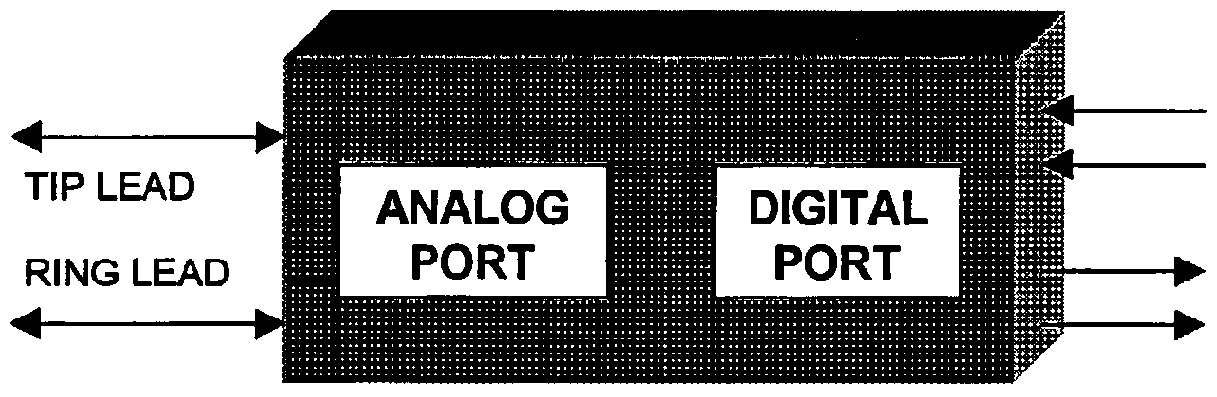
FP-TiM consists of three user programmable ports:
• ANALOG
• DIGITAL
• CONTROL
The analog port connects to analog telephony interfaces, the digital port connects to digital telephony interfaces, and the control port connects to the host processor interface. These three ports allow the designer and user to choose the appropriate telephony interface when the system is configured either in manufacturing, or in the field. This flexibility adds convemence, low cost, and quick time to market to designing modern communication systems or updating existing telephony systems. The module takes care of the many analog interfaces allowing the designer to focus on the digital design aspects ofthe project.
The Field Programmable Telephony interface Module CTPX1001 performs the functions ofthe following devices:
Data Access Arrangement (DAA) Subscriber Line Interface Circuit (SLIQ Universal PBX Line Card
S P 1 UAI rr
+5VdC fL e XiB le Comp u ter Teleph ony Interfa ce Sol tions 11
CTPX
OPERATION
The analog module ports can be configured for Foreign eXchange Subscriber (FXS), Foreign exchange Office (FXO), Dial Pulse Terminating (DPT), and Dial Pulse Originating (DPO) operation The E and M (E&M) and Pulse Link Repeater (PLR) analog port operation can be configured for either 2-wire or 4-wire transmission. The module also supports interfaces with no signaling like Transmission Only (TO) and Equalized Transmission Only (ETO). The module supports the following start-modes: Loop-Start (LS), Ground-Start (GS), Immediate-Start (IS), Wink-Start (WS), and Delay-Dial (DD). The Dial Pulse (DP) addressing information is passed from the analog port to the appropπate Channel Associated output Bits. The Dual Tone Multi Frequency (DTMF) and Multi Frequency (MF) addressing information is converted and passed directly from the analog port into the digital pulse code modulation (PCM) stream. CTPX 1001 supports the basic analog Public Switched Telephone Network (PSTN) interfaces with Loop-Start supervision, Ground-Start supervision, Loop-Reverse-Battery (DID) supervision, E and M (E&M) supervision, and no (NO) supervision.
TELEPHONY FUNCTIONS
• Battery Feed
• Overvoltage Protection
• Ringing
• Supervision
• Codec
• Hybrid
• Testing
OPERATIONAL TASKS
• Converting Analog Signaling to Digital Channel Associated Signaling (CAS)
• Converting Analog Audio to Digital Pulse Code Modulation (PCM)
REGISTER SETTINGS
• Analog Configuration
• Digital Configuration
• Control Configuration
AUTONOMOUS OPERATIONS
• Ring Generation
• Ring Trip
• Ring Detection
• Signal Validation
MODULE CONNECTIONS
• Pin Header
PROGRAMMING TASKS
• Programming
• Configuring
• Operating
fL e XiBle Com pu ter Teleph ony In terfa ce Solu tio n s 12
CTPX
FUNCTIONS
The CTPX1001 provides and enables the common analog Line Card BORSCHT telephone functions.
BATTERY FEED
• Battery Voltage Generation for energizing the lines or trunks.
• Loop Current Detection for recognizing line or trunk seizures.
OVERVOLTAGE PROTECTION
• External Transient Voltage Suppressors for Overvoltage Protection are required for Secondary Protection.
• External Fuses for Current Limitation are required for Secondary Protection.
RINGING
• Ring Pre-Trip Test for checking if the telephone is already Off-Hook before the application of ringing.
• Ring Generation for outgoing calls.
• Ring Detection for incoming calls.
• Ring Trip for shutting off the ring generator when the telephone answers during ringing.
SUPERVISION
• Ring on/Ring off"
• On-hook/Off-hook
• Normal Polarity/Reverse Polarity
• Audio on-hook
• Caller ID protocol
CODEC
• Analog to Digital Conversion
• Digital to Analog Conversion
HYBRID
• 2-Wire to 4-Wire Circuit Conversion
TESTING
• An External Relay is required to provide Test Access.
fL eXiBle Com puter Teleph ony In terfa ce Solution s 13
CTPX
TASKS
CONVERTING
The CTPX1001 interfaces with the following lines or trunks: t
• Loop-Start
• Ground-Start
• Direct-Inward-Dialing
• E&M Lead Signaling
PASSING
The CTPX1001 is transparent for the following payloads, tones, and signals. The information passes between the analog and digital port without modification or intervention:
Voice Information Payload Data Information Payload Fax Information Payload Call Progress Tones Dual-Tone Multi-Frequency Tones Multi-Frequency Tones Dial-Pulse Signals Supervisory Signals
fL eXiBle Com puter Teleph ony In te rfa ce Solution s 14
CTPX
RINGING
The process of alerting the other side of the interface consists of a ring generator, ringer load, ring detector, and ring trip detector.
RINGING PARAMETERS
Ring Voltage (45 Vrms to l50 Vrms)
Ring Frequency (16 Hz to 68 Hz)
Ring Burst (200 ms to 2000 ms)
Ring Silent Interval (200 ms to 4000 ms)
Ring Trip (100 ms to 200 ms)
Ring Pattern (see Alerting)
Ring Cycle (6 seconds)
Ring Duration (from a few ms to a few minutes)
Ring Current (Ring Voltage/Ringer Load)
Ringer Load ((77000000 OOhhmmss aatt 2200 HHzz == RREENN11,, 11440000 OOhhmmss aatt 2200 HHzz = = REN5)
RING GENERATION
The ring generator creates an alternating current (AC) waveform of a specific voltage and frequency. The voltage and frequency requirements may differ from application to application and country to country. The ring generator is turned on for a certain ring burst duration followed by a ring silence interval. The generator rings into the ringer load on the other side of the interface. The application of the ring burst and silence interval is repeated as often as required by the application.
RING DETECTION
The presence of the ringer load causes an alternating current (AC) to flow in the loop. The AC causes the mechanical bell to ring the piezoelectric buzzer to chirp and the electronic ring detection circuit to trigger. If the AC is absent then the ringer load is either disconnected, not present, or the line is not hooked up properly.
RING TRIP
When the other side ofthe interface answers the ringing by going off-hook and entering into a low direct current (DC) resistance state, a ring trip condition is present and the ring generator must be shut off within a specific interval. Ringing should be tripped within a maximum of 200 ms after the transition to the Off-hook State. This requirement should be met regardless weather the off-hook occurred during the ringing or silent interval. A ring-trip interval of less than 100 ms is desirable.
Conditions across the Tip and Ring leads in which ringing should not be tripped:
• A 2uF Capacitor
• Five C4A Ringers
• A lOkOhm Resistive Load
• An Off-Hook Signal less than 12 ms in duration
RING PRE-TRIP TEST
Prior to the application of ringing, the line is being tested for a low resistance condition. The test is performed by briefly applying battery to the line with the tip lead negative with respect to the ring lead. This test checks if the telephone that is connected to the other side of the interface is already in the Off-hook State before the application of ringing.
RINGER LOAD
The ringer load may consist of:
A Mechanical Bell
A Piezoelectric Buzzer
An Electronic Ring Detection Circuit
fL eXiBle Co mp u ter Teleph ony Interfa ce Solu tions 16
CTPX
ALERTING
The individual ring bursts may be of different duration in order to create Distinctive Alerting (DA) patterns. This way different ring cadences can be created for Basic Business Group (BBG) operation.
PATTERNS
DA type 1 code 1 (2.0 s on, 4.0 s off) DA type 1 code 2 (1.0 s on, 1.0 s off, 1.0 s on, 3.0 s off) DA type 2 (0.8 s on, 0.4 s off, 0.8 s on, 4.0 s off) DA type 3 (0.4 s on, 0.2 s off, 0.4 s on, 0.2 s off, 0.8 s on, 4.0 s off)
DA1 CODE 1 PATTERN
DA1 CODE 2 PATTERN
DA2 PATTERN
DA3 PATTERN
φ Two full 6 second ring cycles shown in each figure
f L e XiBle Com puter Teleph ony In te r fa ce S olutions 17
CTPX
LEVELS
DIGITAL MILLIWATT
The reference for setting transmission levels in a telephony communication system is the digital milliwatt. The digital milliwatt is created by a sequence of PCM bytes which generates the 0 dBm, 1000 Hz signal and defines the 0 dB TLP (Transmission Level Point) at the digital interface
Byte l [00001111]
Byte 2 [00000000]
Byte 3 [00000000]
Byte 4 [10011001]
Byte 5 [11111111]
Byte 6 [10011001]
Byte 7 [11111111]
Byte 8 [01100110]
2-WIRE TRANSMISSION
Transmit/Receive 0 dB to -3.0 dB TLP
4-WIRE TRANSMISSION
Receive > +7.0 dB TLP
Transmit -16.0 dB TLP
SUPERVISION
Supervision indicates the condition of a call and shows the readiness of equipment to respond to an attempt to establish or release a connection.
SUPERVISORY STA TES
Supervisory states indicate to equipment, to an operator, or to a caller that a particular state in a call has been reached and may signify the need for action to be taken. A supervisory state may last from a few milliseconds to infinity.
• Idle
• Busy
• Alerting
• Talking
SUPERVISORY EVENTS
Supervisory events indicate a change from one state to a new state. Each port on either side of the interface may establish or terminate the connection. This results in four possible variations of the call scenario.
• Seize
• Answer
• Disconnect
• Hang-up
fL eXiBle Comp uter Teleph on y Interfa ce So lu tions 18
CTPX
SIGNALING
There are four major analog signaling facilities:
• Loop Signaling (LS, GS, LRBS) supported by CTPX 1001
• E&M Signaling (E&M, PLR) supported by CTPX1001
• Duplex Signalmg (DX) not supported by CTPX1001
• Single Frequency Signaling (SF) not supported by CTPX1001
SIGNALING METHODS
The way by which a Loop or E&M type telephony port notifies the other side of a change in state is limited to five primary signaling methods:
LOOP open or closed loop indicates the idle or off-hook state
BATTERY normal or reverse battery indicates the idle or answered state
RINGING no ringing or AC ringing indicates the idle or alerting state
E-LEAD open or ground E-lead indicates the idle or seized state
M-LEAD ground/open or battery/ground M-lead indicates the idle or seized state
SIGNAUNG TERMINALS
The signaling terminals of analog telephony interfaces are:
• T-Lead Tip terminal ofthe 2-Wire port (4-wire transmit output)
• R-Lead Ring terminal of the 2-Wire port (4-wire transmit output)
• Tl-Lead Tip terminal ofthe 4-Wire port (4-wire receive input)
• Rl-Lead Ring terminal ofthe 4-Wire port (4-wire receive input)
• E-Lead E terminal of the E&M port
• M-Lead M terminal ofthe E&M port
• SG-Lead Signal Ground terminal ofthe E&M port
• SB-Lead Signal Battery terminal ofthe E&M port
SIGNAUNG LEADS
The number of signaling leads depends on the type of interface selected:
• 2 leads Loop-Start, Ground-Start, and Loop-Reverse-Battery (DID)
• 4 leads 2-Wire, E&M, Type I and V signaling
• 6 leads 2-Wire, E&M, Type D., m, and IV signaling
• 8 leads 4-Wire, E&M, Type 0; m, and IV signaling
SIGNALING TYPES
There are five different signaling types used exclusively for interfaces with E&M supervision. The types differ physically and electrically.
TYPE I E: open when idle ground when seized (ground return required)
M: ground when idle battery when seized (ground return required)
TYPE Π E: open when idle ground when seized (no ground return required)
M: open when idle battery when seized (no ground return required)
TYPE ΓH E: open when idle ground when seized (no ground return required)
M: ground when idle battery when seized (no ground return required)
TYPE IV E: open when idle ground when seized (no ground return required)
M: open when idle ground when seized (no ground return required)
TYPE V E: open when idle ground when seized (ground return required)
M: open when idle ground when seized (ground return required) fL eXi Ble Co mp u ter Teleph o ny Interfa ce So lu tio ns 19
CTPX
INTERFACES
An interface is the boundary between two pieces of equipment across which all signals pass. The interface definition includes:
• Physical Connector
• Transmit and Receive Levels
• Audio Impedance
• Signal Timing
• Sequence of Events
• Meaning of Signals.
There are two sides to every telephony interface. The telephone cable connects one side to the other side. An equipment port terminates each side. One port generates an event or function while the other port detects the event or function and acts on it accordingly. The equipment ports are generally described as:
• Central Office (CO)
• Customer Premise Equipment (CPE)
• Private Branch Exchange (PBX)
There are five common analog interfaces. Each has a specific purpose and different operation:
• Interface with Loop-Start Supervision
• Interface with Ground-Start Supervision
• Interface with Loop-Reverse-Battery Supervision
• Interface with E&M Lead Supervision
• Interface with No Supervision
Loop-Start example: On a loop-start (POTS) line the Central Office (CO) generates ringing while the telephone (CPE) that is connected to the CO detects the ringing and alerts the called party.
• The CO port generates battery and the CPE port detects battery.
• The CO port generates ringing and the CPE port detects ringing.
• The CO port generates dial tone and the CPE port detects dial tone.
• The CPE port generates off-hook and the CO port detects off-hook.
• The CPE port generates digits and the CO port detects digits.
• The CPE port generates on-hook and the CO port detects on-hook
Loop-Reverse Battery example: On a Direct-Inward-Dialing (DID) trunk the Central Office (CO) goes off-hook and does the dialing while the private branch exchange (PBX) trunk port powers the trunk.
• The PBX port generates battery and the CO port detects battery.
• The PBX port generates normal polarity and the CO port detects normal polarity.
• The PBX port generates reverse polarity and the CO port detects reverse polarity.
• The CO port generates off-hook and the PBX port detects off-hook.
• The CO port generates digits and the PBX port detects digits.
• The CO port generates on-hook and the PBX port detects on-hook.
On most analog interfaces both sides are not the same. There are electrical differences between both interface ports. The only analog ports without electrical differences are the interfaces with No Supervision and the E&M type V interface. The E&M type V interface is mainly used with ITU compliant equipment. fL eXiBle Comp u ter Teleph ony In te r fa ce S olutions 20
CTPX
INTERFACE WITH LOOP-START SUPERVISION
This interface is often referred to as Plain-Old-Telephone-Service (POTS). "Plain-Old-Telephone-Service" is a service provided by the Central Office for common in-bound and out-bound call traffic. Loop-start is a form of signaling in which the end office supplies battery between tip and ring conductors. A terminal indicates an off-hook state by allowing current to flow. Loop refers to the closing of switch contacts across the tip and ring conductors to allow current to flow in the telephone loop. The interface with loop-start supervision is normally not polarity sensitive However, it is good practice to always connect the tip-lead from one side to the tip-lead ofthe other side and connect the ring-lead from one side to the ring-lead from the other side.
The following equipment ports are part of this interface:
• Foreign Exchange Office (FXO)
• Foreign Exchange Subscriber (FXS)
This interface is used to connect:
• CO to Telephone
• CO to Key Telephone System
• CO to FAX/Modem
• PBX to Station Set or Telephone
• PBX to Voice Messaging System
• PBX to FAX/Server
Loop-Start Trunk States
Conditions No Ringing Ringing
Open Loop Idle Alerting
Closed Loop Seized Talking
Advantages: Most common interface with the most simple call set-up.
Disadvantages: Off-hook signals can collide and lock up the trunk, causing a condition called""Glare."
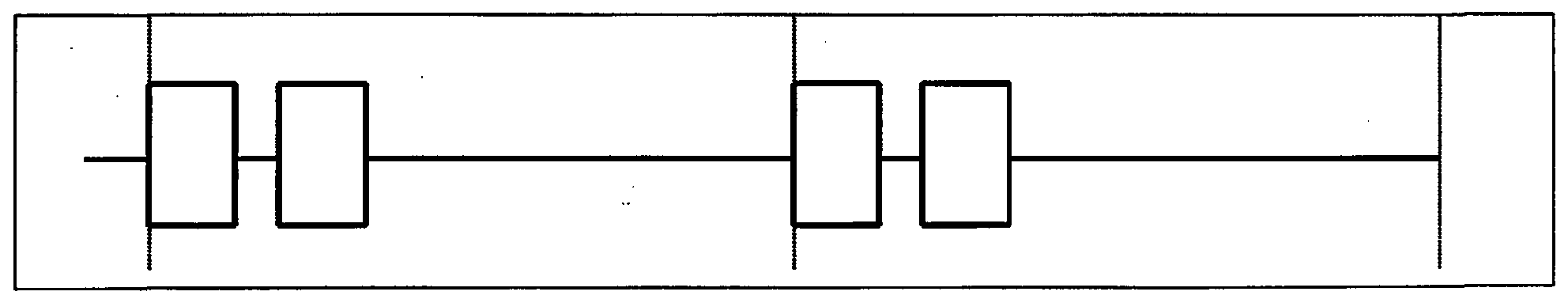
Loop-Start Tip and Ring Voltage Diagram
Idle Alerting Answer Talking Flash Disconnect Jlr oJlJjxel .
fL e XiBle Com pu ter Teleph ony In te rfa ce Solu tions 21
CTPX
H = High DC resistance loop (greater than 30,000 Ohms).
L = Low DC resistance loop (100 Ohms to 2,400 Ohms).
N = Normal battery with the tip lead at ground potential (+Vdc) and the ring lead at battery potential (-Vdc).
O = Open circuit condition (Battery and/or ground leads are removed from the circuit).
X = Any condition
fLeXiBle Computer Telephony lηtejrface Solutions 22
CTPX
INTERFACE WITH GROUND-START SUPERVISION
This interface most commonly connects the trunk side of a PBX to the servicing Central Office. Ground-start is a form of signaling in which grounding a wire indicates a request for service by either interface side. The interface with ground-start supervision is polarity sensitive. Always connect the T-lead from one side to the T-lead of the other side and connect the R-lead from one side to the R-lead from the other side. If the T-lead and the R-lead are reversed, the PBX will not be able to initiate out-bound calls.
The following equipment ports are part of this interface:
• Foreign Exchange Office (FXO)
• Foreign Exchange Subscriber (FXS)
This interface is used to connect:
• CO to Private Branch Exchange
Interface With Ground-Start Supervision
Ground-Start Trunk States
Advantages: Automatic resolutions of call collisions ("Glare"). Disadvantages: Complicated call set-up.
Ground-Start Tip/Ring Voltage Diagram
Idle Seize Alerting Answer Talking Flash Disconnect Idle
f L eXiB le Com pu te r Te lephony In terfa ce Solu tio ns 23
CTPX
H = High DC resistance loop (greater than 30,000 Ohms).
L = Low DC resistance loop (100 Ohms to 2,400 Ohms).
N = Normal battery with the tip lead at ground potential (+Vdc) and the ring lead at battery potential (-Vdc).
O = Open circuit condition (Battery and/or ground leads are removed from the circuit).
X = Any condition
fLeXiBle Computer Telephony Interface Solutions 24
CTPX
INTERFACE WITH LOOP-REVERSE-BATTERY SUPERVISION (DID)
This interface is also known as Direct-Inward-Dialing Service or DID service. DID is a function provided by the Central Office for in-bound call traffic only. The customer premise equipment (PBX/VMS) typically receives the last 3 to 7 digits of the telephone number dialed by the caller through the Central Office which is coifiiected at the other side of the DID trunk. The PBX/VMS uses the DID digits to route and place the call to a specific person (station) or during a ring-no- answer/busy-no-answer condition to an individual mailbox. The loop-reverse-battery-signaling interface is polarity sensitive. It makes a difference which way the tip and ring wires are hooked up to the public switched telephone network. If the wires are reversed, the trunk busies out and the caller may hear the all-trunks-busy or fast busy signal.
The following equipment ports are part of this interface:
• Dial Pulse Originating (DPO)
• Dial Pulse Terminating (DPT)
This interface is used to connect:
• CO to Private Branch Exchange
• CO to Voice Messaging System
• PBX to Voice Messaging System
• PBX to Telephone Answering System
• TAS to Voice Messaging System
Interface With Loop-Reverse-Battery (DID) Supervision
Advantages: Direct station access, direct voice mail access, and direct fax access.
Disadvantages: Polarity sensitivity may cause wiring problems. T must be connected to T and R must be connected to R.
Loop-Reverse-Battery (DD3) Tip/Ring Voltage Diagram
Idle Seizure Wink Addressing Ringback Answer Talking Flash CO Disconnect Idle
Normal on-hook f L eXiB le Compu ter Te lephony lπ te$£a ce Solu tio ns 25
CTPX
H = High DC resistance loop (greater than 30,000 Ohms).
L = Low DC resistance loop (100 Ohms to 2,400 Ohms).
N = Normal battery with the tip lead at ground potential (+Vdc) and the ring lead at battery potential (-Vdc).
R = Reverse battery with the tip lead at battery potential (-Vdc) and the ring lead at groimd potential (+Vdc).
O = Open circuit condition (Battery and/or ground leads are removed from the circuit).
X = Any condition
fLeXiBle Computer Telephony Interface Solutions 26
CTPX
INTERFACE WITH E&M LEAD SUPERVISION
The term E&M describes interfaces used by switches within the confines of a building. E&M signaling is not used in outside wiring. On an E&M trunk, the carrier facilities or PBX Tie Lines may dial many or no digits in DTMF or MF via in-band signaling or Dial Pulse via E-lead or M-lead out-of-band signaling. The switth uses the digits to route and place the call to a specific person (station) or during a ring-no-answer/busy-no-answer condition to an individual mailbox. The term E&M originates from the old Ear and Mouthpieces associated with early telephones. The E and M lead-signaling interface is wiring sensitive. Always connect the E-lead from one side to the E-lead of the other side. If the E and M-lead are hooked up reversed, the interface will not operate as expected
The following equipment ports are part of this interface:
• E and M Signaling (E&M)
• Pulse Link Repeater (PLR)
This interface is used to connect:
• PBX to Private Branch Exchange
• PBX to Channel Bank
• PBX to Carrier Facilities
• PBX to Tie Trunks
The Interface With E&M Supervision
E- and M-Lead Trunk States
Advantages: Quiet call control. No clicking noise when answering, hook-flashing or disconnecting. Disadvantages: More than two wires required. Lead hook-up may cause some wiring errors.
E-Lead or M-Lead Voltage Diagram
Idle Wink Seize Connect Flash Connect Disconnect Idle
On-hook Level
1 r Off-hook Level
f L eXiBle Comp u ter Teleph o ny In terfa ce Soluti o ns 27
CTPX
E and M Type I and Type in Line Signaling
Line States Interface Conditions Comments
M E
Idle Ground Open Trunk is waiting for a new call
PLR Seizure Battery Open PLR lands a new call on the E&Mltrunk
E&M Seizure Ground Ground E&M lands a new call on the E&M trunk
Connect Battery Ground Called party and calling party are communicating
E and M Type II Line Signaling
Line States Interface Conditions Comments
£
Idle Open Open Trunk is waiting for a new call
PLR Seizure Battery Open PLR lands a new call on the E&M trunk
E&M Seizure Open Ground E&M lands a new call on the E&M trunk
Connect Battery Ground Called party and calling party are communicating
E and M Type TV and Type V Line Signalir ιg
Line States Interface Conditions Comments
M E
Idle Open Open Trunk is waiting for a new call
PLR Seizure Ground Open PLR lands a new call on the E&M trunk
E&M Seizure Open Ground E&M lands a new call on the E&M trunk
Connect Ground Ground Called party and calling party are communicating
Open = High DC resistance loop (greater than 20,000 Ohms). Looped = Low DC resistance loop (0 Ohms to 2,400 Ohms). Battery = Battery potential (-Vdc). Ground = Ground potential (+Vdc).
fL e XiBle Com puter Telep hon y In te rfa ce Solution s 28
CTPX
INTERFACE WITH NO SUPERVISION
No supervision indicates that the trunk is a "dry" circuit. "Diy" means that there is no battery power or flow of any current involved. There is also no signaUng associated with this kind of interface. The talk-path consists of a balanced wire pair and is suitable for long haul signal transmissions. The signaling interface without any supervision is not wiring sensitive. However, it is good practice to always connect the T-lead from one side to the T-lead of the other side and connect the R-lead from one side to the R-lead from the other side. The Interface with no supervision maintains a constant and direct talk-path connection to the other side.
The following equipment ports are part of this interface:
• Transmission Only ('TO')
• Equalized Transmission Only (ETO)
This interface is used to connect:
• Switch to Leased Line
• Switch to Paging Terminal
• Switch to Satellite Terminal
The Inl erface with NO Supervision C )iagram
ETO and TO Trunk State
Advantages : Direct connection between equipment. Disadvantages: No call control or supervision.
f L eXiBle Com pu te r Telephon y In terfa ce Solu tio n s 29
CTPX
PORTS
FOREIGN EXCHANGE OFFICE (Loop-Start) i
The Foreign Exchange Office port looks like a 2500 type telephone station set. This port is also referred to as the CPE side ofthe loop-start interface. Its counterpart is the FXS port configured for loop-start supervision.
Abbreviation FXO'
Alerting RINGING
CAS Bits A and B
Signaling Type NONE
Start-Mode LOOP-START
Transmission 2-WIRE
Wire terminals TIP and RING
The FXO Port in Loop-Start Mode
d LOOP
RINGING -» <r LOOP
f L eXiBle Comp u ter Teleph ony In te rfa ce S olutions 30
CTPX
FOREIGN EXCHANGE SUBSCRIBER (Loop-Start)
The Foreign Exchange Subscriber port looks like a telephone wall outlet jack when configured for loop-start supervision. This port is also referred to as the CO side of the loop-start interface. Its counterpart is the FXO port configured for loop-start supervision.
Abbreviation 'FXS' Alerting RINGING CAS Bits an B Signaling Type NONE Start mode LOOP-START Transmission 2-WIRE Wire terminals TD? and RING
The FXS Port in Loop-Start Mode
RINGING
LOOP -» <r RINGING
fL eXiBle Comp uter Teleph ony In terfa ce S olutions 31
CTPX
FOREIGN EXCHANGE OFFICE (Ground-Start)
The Foreign Exchange Office port in ground-start mode looks like a PBX trunk circuit. This port is also referred to as the PBX trunk side of the ground-start interface. Its counterpart is the FXS port configured with ground-start supervision. l
Abbreviation 'FXO' Alerting RINGING CAS Bits andB Signaling Type NONE Start mode GROUND-START Transmission 2-WIRE Wire terminals TIP and RING
The FXO Port in Ground-Sta rtMode
RCV A = rrlnse 1 OOP RCV B = R-GROUND
XMT A - T-GROUND XMT = no RINGIN
RINGING -» <r ■LOOP T-GROUND -» « ■ R-GROUND
fLeXiBle Computer Telephony Interface Solutions 32
CTPX
FOREIGN EXCHANGE SUBSCRIBER (Ground-Start)
The Foreign Exchange Subscriber port in ground-start mode looks like a CO network interface circuit. This port is also referred to as the CO side of the ground-start interface. Its counterpart is the FXO port configured for ground-start supervision.
Abbreviation 'FXS' Alerting RINGING CAS Bits A and B Signaling Type NONE Start Mode GROUND-START Transmission 2-WIRE Wire terminals TIP and RING
The FXS Port in Ground-Start Mode
RCV A = T-GROUND RCV B = no RINGING
XMT A = closed LOOP XMT B = R-GROUND
LOOP -* BRINGING R-GROUND-* <-T-GROUND
fL eXiBle Co u ter Teleph ony In te rfa ce Solution s 33
CTPX
DIAL PULSE ORIGINATING
The Dial Pulse Originating port looks like a CPE trunk circuit configured for loop-reverse-battery supervision. This port is also referred to as the CPE side of DID trunk. Its counterpart is the DPT port.
Abbreviation 'DPO' Alerting NONE CAS Bits A=B Signaling Type NONE Start Modes IMMEDIATE, WINK, and DELAY-DIAL Transmission 2-WπtE Wire terminals TIP and RING
The DPO Port
LOOP-* <r BATTERY
fLeXiBle Computer Telephony Interface Solutions 34
CTPX
DIAL PULSE TERMINATING
The Dial Pulse Terminating port looks like a CO network interface circuit configured for loop-reverse-battery supervision. This port is also referred to as the CO side ofthe DID trunk. Its counteipart is the DPO port.
Abbreviation DPT' Alerting NONE CAS Bits A = B Signaling Type NONE Start Mode IMMEDIATE, WINK, and DELAY-DIAL Transmission 2-WIRE Wire terminals TIP and RING
fLeXiBle Computer Telephony Inte f^^ Solutions 35
CTPX
E&MSIGNALING
The E&M signaling port looks like a signaling circuit configured for E&M supervision. This port is also referred to as the normal E&M side of the E and M signaling interface. Its counterpart is the PLR port.
Abbreviation 'E&M' Alerting NONE CAS Bits A=B Signaling Type I,Π,ΠLIV,V Start Mode IMMEDIATE, WINK, and DELAY-DIAL Transmission 2-WIRE and 4-WIRE Wire terminals T, R, TI, RI, E, M, SG, and SB
The E&M Port
fLeXiBle Computer Telephony Interface Solutions 36
CTPX
PULSE LINK REPEATER
The Pulse Link Repeater looks like a trunk circuit configured for E&M supervision. This port is also referred to as the reverse E&M side ofthe E and M signaling interface. Its counterpart is the E&M port.
Abbreviation PLR' Alerting NONE CAS Bits A=B Signaling Type Π,Π IV,V Start Mode IMMEDIATE, WINK, and DELAY-DIAL Transmission 2-WIRE and 4-WERE Wire terminals T, R, TI, RI, E, M, SG, and SB
The PLR Port
fLeXiBle Computer Telephony Interface, Soluti ons 37
CTPX
TRANSMISSION ONLY
The Transmission-Only port looks like a two-wire terminal circuit configured for no supervision. This port is also referred to as the 2-wire dry voice circuit This port may carry talk-path information in either direction on the same wire pair. The advantage of the TO is that transmit and receive signals are carried on one wire pair only. Its counterpart is the TO port.
Abbreviation TO'
Signaling Type NONE
Start Mode NONE
Transmission 2-WIRE
Wire terminals T, R
The TO Port
fL eXiBle Comp u ter Teleph ony Interfa ce S o lu tions 38
CTPX
EQUALIZED TRANSMISSION ONLY
The Equalized Transmission-Only port looks like a four-wire terminal circuit configured for no supervision. This port is also referred to as the 4-wire dry voice circuit. The port carries transmit and receive talk-path information on separate wire pairs. The advantage ofthe ETO is that signals can easily be amplified, attenuated, or equalized as required. Each wire pair of this four-wire circuit has to be defined as transmit only and receive only port. Its counterpart is the ETO port.
Abbreviation ETO' Alerting NONE CAS Bits does not care Signaling Type NONE Start Mode NONE Transmission 4-WIRE Wire terminals T, R, TI, and RI
ETO Analog Port Signaling to CAS Signaling Bit Conversion
Input To Port XMT A XMT B RCV A RCV B Output From Port
No SIGNALING No SIGNALING
fL eXiB le Compu te r Te lepho n y I n terfa ce Solu tio ns 39
CTPX
CAS-BITS
MANIPULATION
NORMAL A
From Analog interface -^ A normal A -> to Digital Interface
INVERTED A
From Analog Interface - A invert A -^ to Digital Interface
NORMAL A SWAPPED TO B From Analog Interface -* A normal B -> to Digital Interface
INVERTED A SWAPPED TO B From Analog Interface -^ A invert B -> to Digital Interface
NORMAL B
From Analog interface -> B normal B -> to Digital Interface
INVERTED B
From Analog Interface -> B invert B -> to Digital Interface
NORMAL B SWAPPED TO A From Analog Interface -> B normal A -> to Digital Interface
INVERTED B SWAPPED TO A From Analog Interface -* B invert A -* to Digital Interface
fL eXiBle Co puter Telep h ony In te rfa ce S olution s 40
CTPX
CONDITIONS
When High:
The A-Xmt bit from the FXO/LS port indicates a remote condition of FIXED LOW BIT LEVEL
The A-Xmt bit from the FXO/GS port indicates a remote condition of TJP-GROUND
The A-Xmt bit from the FXS/LS port indicates a remote condition of CLOSED LOOP
The A-Xmt bit from the FXS/GS port indicates a remote condition of CLOSED LOOP
The A-Xmt bit from the DPO port indicates a remote condition of CLOSED LOOP
The A-Xmt bit from the DPT port indicates a remote condition of REVERSE POLARITY
The A-Xmt bit from the E&M port indicates a remote condition of M-LEAD SEIZURE
The A-Xmt bit from the PLR port indicates a remote condition of E-LEAD SEIZURE
The A-Xmt bit from the ETO port indicates a remote condition of NO EFFECT
The A-Xmt bit from the TO port indicates a remote condition of NO EFFECT
When Hi h:
The B •X bit from the FXO/LS port indicates a remote condition of NO RINGING The B -Xmtbit from the FXO/GS port indicates a remote condition of NO RINGING The B -Xmtbit from the FXS/LS port indicates a remote condition of FIXED HI BIT LEVEL The B' ■Xmt bit from the FXS/GS port indicates a remote condition of RING-GROUND The B Xmtbit from the DPO port indicates a remote condition of CLOSED LOOP The B- ■Xmtbit from the DPT port indicates a remote condition of REVERSE POLARITY The B- ■Xmtbit from the E&M port indicates a remote condition of M-LEAD SEIZURE The B- •Xmtbit from the PLR port indicates a remote condition of E-LEAD SEIZURE The B- ■Xmtbit from the ETO port indicates a remote condition of NO EFFECT The B- ■Xmt bit from the TO port indicates a remote condition of NO EFFECT
When High:
The A- ■Rev bit to the FXO/LS port creates a local setting of CLOSED LOOP The - •Rrcv bit to the FXO/GS port creates a local setting of CLOSED LOOP The A- ■Rev bit to the FXS/LS port creates a local setting of NO EFFECT The A- ■Rev bit to the FXS/GS port creates a local setting of TD?-GROUND The A- Rev bit to the DPO port creates a local setting of REVERSE POLARITY The A- Rev bit to the DPT port creates a local setting of CLOSED LOOP The A- Rev bit to the E&M port creates a local setting of E-LEAD SEIZURE The A- Rev bit to the PLR port creates a local setting of M-LEAD SEIZURE The A- Rev bit to the ETO port creates a local setting of NO EFFECT The - Rev bit to the TO port creates a local setting of NO EFFECT
When High: The B •Rev bit to the FXO/LS port creates a local setting of NO RINGING The B ■Rev bit to the FXO/GS port creates a local setting of NO RINGING The B Rev bit to the FXS/LS port creates a local setting of FIXED HI BIT LEVEL The B Rev bit to the FXS/GS port creates a local setting of RING-LEAD GROUND The B Rev bit to the DPO port creates a local setting of CLOSED LOOP The B Rev bit to the DPT port creates a local setting of REVERSE POLARITY The B ■Rev bit to the E&M port creates a local setting of M-LEAD SEIZURE The B ■Rev bit to the PLR port creates a local setting of E-LEAD SEIZURE The B ■Rev bit to the ETO port creates a local setting of NO EFFECT The B ■Rev bit to the TO port creates a local setting of NO EFFECT
fL e XiBle C om pu ter Teleph ony ln te rfa ce_^S olu tion s 41
CTPX
CONVERSIONS
This set of diagrams shows a couple examples of direct conversion. Direct conversion is based on a straight A-bit to A-bit and B-bit to B-bit conversion.
Loop-Start
Ground-Start
E and M Lead Signaling (with 4-Wire to 2-Wire Conversion example shown)
No Supervision (with 2-Wire to 4-Wire Conversion example shown)
-* To Terminal <- From Terminal
fLeXiBle Computer Telephony Interface Solutions 42
CTPX
SPECIFICATIONS
PORTS PER MODULE
Analog Port 1 Digital Port 1 Control Port 1
ANALOG INTERFACES
Foreign Exchange Subscriber FXS (Loop-Start or Ground-Start) Foreign Exchange Office FXO (Loop-Start or Ground-Start) Dial Pulse Originating DPO (Loop-Reverse-Battery-Signaling, DID) Dial Pulse Terminating DPT (Loop-Reverse-Battery-Signaling, DID) E&M Lead Signaling E&M (2-Wire or 4-Wire) Pulse Link Repeater PLR (2-Wire or 4-Wire) Equalized Transmission Only ETO (4-Wire) Transmission Only TO (2-Wire)
DIGITAL INTERFACES
CONTROL INTERFACES
SPI Interface 3-Wire Synchronous UART Interface 2-Wire Asynchronous
TERMINATION
Analog Port 9-Pin SIP (Header with 2-mm pitch) Digital Port 9-Pin SD? (Header with 2-mm pitch) Control Port 9-Pin SD? (Header with 2-mm pitch)
POWER REQUIREMENTS
Voltage +5 Vdc (Nominal) Tolerance +/-5 % (Maximum) Current 0.1 A (Maximum) Power 0.5 W (Maximum)
DIMENSIONS -
Length 3.750 « (9.525 cm)
Depth 1.065 " (2.705 cm)
Height 0.540 « (1.372 cm)
ENVIRONMENTAL
Operating Temperature +32 °F to +104 °F (0 °C To 40 °C) Storage Temperature -40 °F to +185 °F (-40 °C To +85 °C) Humidity 5 % to 95 % (non Condensing)
WEIGHT
Net Weight l Oz (28 g) f L eXiBle Compu ter Te lephony In terfa ce Solu tio ns 43
CTPX
TECHNICAL DATA
PRODUCT
fLeXiBle Co puter Telephony Interface Solutions 44
CTPX
NETWORK
ABSOLUTE MAXIMUM RATINGS
fLeXiBle Computer Telephony Interf t^Solutions 45
CTPX
CHARACTERISTICS
ELECTRICAL
TRANSMISSION
TIMING
PCM
SPI
UART
fLeXiBle Computer Telephony Interface Solutions 46
CTPX
MNEMONICS
EXTERNAL
ANALOG PORT
The Analog port consists ofthe 2-Wire and 4-Wire interface terminals.
T TIP-LEAD 4-Wire E&M Transmit or 2-Wire E&M Transmit/Receive
R RING-LEAD 4-Wire E&M Transmit or 2-Wire E&M Transmit Receive
TI T P 1 -LEAD 4-Wire E&M Receive
RI RINGl-LEAD 4-Wire E&M Receive
E E-LEAD or 2-Wire LOOP, Tip-Lead
M M-LEAD _ or 2-Wire LOOP, Ring-Lead
SG SIGNAL GROUND-LEAD
SB SIGNAL BATTERY-LEAD
TRC TELECOM REFERENCE CONDUCTOR or PROTECTIVE EARTH (PE)
DIGITAL PORT
The digital port consists ofthe PCM interface and the CAS interface terminals.
The PCM interface controls the serial media stream via the following leads:
• BCLK PCM, Bit Clock Input
• FSRX PCM, Frame Synchronization Pulse Input
• DR PCM, Data Receive, Stream Input
• DX PCM, Data Transmit, Stream Output
• TSX PCM, Timeslot, Transmit Enable, Stream Output
The CAS interface controls the parallel signaling bits via the following leads:
• ARCV CAS BIT, A Receive Input
• BRCV CAS BIT, B Receive Input
• AXMT CAS BIT, A Transmit Output
• BXMT CAS BIT, B Transmit Output
The +5 Vdc module power is connected to the following leads:
• VDD POWER +5.00 Vdc Supply
• GND GROUND +5.00 Vdc Return
CONTROL PORT
The control port consists ofthe SPI interface and the UART interface terminals.
The SPI Interface is a 3 -Wire synchronous communication method using the following leads:
• RST RESET Input
• SCK SPI Clock Input
• CSS SPI Chip Select Input
• SDO SPI Data Output
• SDI SPI Data Input
The UART Interface is a 2-Wire asynchronous communication method using the following leads:
• RXD UART, Receive Input
• TXD UART, Transmit Output
f L eXiBle Compu te r Telephony In terfa ce Sol tion s 47
CTPX
OUTLINE
φ All dimensions are in inches
Header Pin Length is 0.235" φ The Drawing is not to scale. fLeXiBle Comp ter Telephony Interface Solutions 48
CTPX
fLeXiBle Computer Telephony Interface Solutions 49
CTPX
PIN-OUT
φ Bottom View. Looking directly onto the header pins.
φ All dimensions are in inches fLeXiBle Computer Telephony Interface Solutions 50
CTPX
NOTICES
WARNINGS When using your telephone equipment, basic safety precautions should always be followed to reduce the risk of fire, electric shock, and injury to persons, including the following:
• Read and understand all instructions
• Follow all warnings and instructions
• Unplug the module from the telecom connector before cleaning
• Use a damp cloth for cleaning
• Do not use liquid cleansers or aerosol cleaners
• Do not use this product near water
When installing this module into your system, please make sure that the module earth ground pin is securely connected to the systems chassis or telecom reference conductor terminal and that the system is plugged into a grounded three-prong outlet. Incorrect grounding can result in harmful or fatal electrical shock or component damage.
Use caution when installing or modifying telephone lines.
® Changes or modifications to this product not expressly approved by the party responsible for compliance could void the user's authority to operate the equipment
f eXiB le Compu te r Telep h on y In terfa ce Solu tions 51
CTPX
HANDLING
Proper care must be taken when handling and installing the module:
• Observe the absolute maximum ratings for all ports
• Avoid exposure to electrostatic discharge (ESD)
• Prevent the application of reverse polarity to logic Power (+5 Vdc)
• Provide filtered logic power to the module
• Never plug or unplug the module while powered
fL e XiBle Com puter Teleph ony In te rfa ce Solution s 52
CTPX
FCC PART 68
The Federal Communications Commission (FCC) has established rules that permit CTPX1001 to be directly connected to the public switched telephone network (PSTN). Standardized jacks are used for these connections. CTPX 1001 should not be used on party lines or coin lines. ι
If CTPX1001 is malfunctioning, it may be causing harm to the telephone network. CTPX1001 should be disconnected until the source of the problem can be determined and until repair has been made. If repair is not done, the . Telephone Company may temporarily disconnect service.
The Telephone Company may make changes in its technical operations and procedures; if such changes affect the compatibility of CTPX1001, the Telephone Company is required to give adequate notice of the changes. You will be advised of your right to file a complaint with the FCC.
If the Telephone Company requests information on what equipment is connected to their lines, please inform them ofthe following:
• The Telephone Number This Unit Is Connected To (NBR #)
• The Ringer Equivalence Number (REN #)
• The User Order Code Jack Required (USOC #)
• The Service Order Code (SOC #)
• The Facility Interface Code (FIC #)
• The FCC Registration Number (FCC #)
DID INFORMATION
Allowing this equipment to be operated in such manner as not to provide proper answer supervision is in violation of part 68 ofthe FCC rules.
And:
PROPER ANSWER SUPERVISION IS WHEN:
This equipment returns answer supervision to the PSTN when DID calls are:
• Answered by the called station
• Answered by an attendant
• Routed to a recorded announcement that can be administered by the CPE user
• Routed to a dial prompt
This equipment returns answer supervision for all direct-inward-dialing calls forwarded to the PSTN. Permissible exceptions are:
• A call is unanswered
• A busy tone is received
• A reorder tone is received
f L eXiBle Com ute r Te lephon y In terfa ce Solu tions 53
CTPX
FCC PART 15
This equipment has been tested and found to comply with the limits for a class B digital device, pursuant to part 1 of the FCC rules. These limits are designed to provide reasonable protection against harmful interference when the equipment is operated in a residential installation. This equipment generates, uses, and can radiate radio frequency energy and, if not installed and used in accordance with the instruction manual, may cause harmful interference to radio communications. However, there is no guarantee that interference will not occur in a particular installation. If this equipment does cause harmful interference to radio or television reception, which can be determined by turning the equipment off and on, the user is encouraged to try to correct the interference by one or more ofthe following measures:
RFI INFORMATION
• Re-orient or relocate the receiving antenna.
• Increase the separation between the equipment and the receiver.
• Connect the equipment into an outlet on a circuit different from that to which the receiver is connected.
• Consult the dealer or an experienced radio/television technician for help.
fL eXiBle Com puter Telep h ony In terfa ce Solution s 54
CTPX
APPENDIX
DIGIT CHARACTER SETS
DIAL PULSE
DUAL TONE MULTI FREQUENCY
MULTI FREQUENCY
fLeXiBle Computer Telephony Interface Solutions 55
CTPX
PULSE DIALING
Pulse dial addressing is used for loop and E&M analog signaling facilities. The process of dialing the dial-pulse addressing digits consists of a series of break and make signals separated by an interdigital period (IDP).
DIAL-PULSE PARAMETERS
DP Digits (digit zero to digit nine)
DP Interdigital Period (180 ms to ∞ ms typical range) (300 ms nominal value)
DP Speed (8 pps to 12 pps typical range) (10 pps nominal value)
DP Break Ratio (40 % to 80 % typical range) (64 % nominal value)
Dial-Pulse Voltage Diagram
Off-Hook Level
On-Hook Level
1st break followed by 1st make followed by 1st IDP represents the digit one 2 breaks and 2 makes followed by 2nd IDP represents the digit two
3 breaks and 3 makes followed by 3rd IDP represents the digit three
4 breaks and 4 makes followed by constant off -hook represent the digit four
DIGITS
The dial pulse digits consist of the numbers 0 - 9. The individual dial-pulse digit ONE is represented by 1 break. The digit ZERO is represented by a series of 10 consecutive breaks.
INTERDIGITAL PERIOD
The spacing between two digits is represented by the interdigital period and marks the boundary between two consecutive digits and the end ofthe last digit.
SPEED
The dial pulse digits consist of the numbers 0 - 9. The individual dial-pulse digit "one" is represented by 1 break. The digit ZERO is represented by a series of 10 consecutive breaks. This measure is expressed in pulses per second.
BREAK RATIO
The break time is often expressed as a percent of the break plus make period. This ratio represents a measure of dial pulsing and is often called "percent break."
f L e XiBle Com puter Telep h ony In te rfa ce S olutions 56
CTPX
START-MODES
Start-modes are associated with specific interfaces. The start mode defines how the trunk/line call scenario proceeds after the initial "Request-for-Service" or seizure signal. In most cases the release of the addressing digits is dependent on an acknowledge signal in response to the trunk/line seizure.
• Loop-Start
• Ground-Start
• Immediate-Start
• Wink-Start
• Delay-Dial
LOOP-START
A form of signaling for FXS and FXO ports, in which one side of the interface closes the loop The LOOP is closed to indicate the readiness to process the call Start dialing digits after detecting the dial tone.
GROUND-START
A form of signaling for FXS and FXO ports, in which one side ofthe interface grounds a wire to indicate a request for service. The GROUND is applied to a lead to indicate the readiness to process the call. Start dialing digits after detecting the dial tone.
IMMEDIATE-START
A form of signaling for DPT, DPO, E&M, and PLR ports, in which immediately after the trunk seizure, the addressing digits are being released. The IMMEDIATE release of the addressing digits happens regardless whether the other interface side is ready to receive the digits or not. Start dialing digits a short time after the seizure signal.
WINK-START
A form of signaling for DPT, DPO, E&M, and PLR ports, which is based on hand shaking between the two interface sides. After a trunk seizure the other side acknowledges the readiness to process the call by a brief transition to the Off-hook State. The WINK lets the seizing side ofthe interface know that it is now ready to receive the addressing digits. Start dialing digits after reception ofthe wink signed.
DELAY-DIAL
A form of signaling for DPT, DPO, E&M, and PLR ports, which is based on hand shaking between the two interface sides. After a trunk seizure the other side returns the off-hook condition while idle. The off-hook signal remains until the port is ready to process the call. This process allows a controlling DELAY ofthe addressing digit release. Start dialing digits after release ofthe delay- dial signal
fL eXiBle Com puter Teleph ony In terfa ce S olution s 57
CTPX
HUNTING
Trunks or lines are oftentimes combined to form logical groups for specific in-bound or out-bound applications. For different reasons different hunt-group arrangements are available.
• Sequential Hunt-Group
• Circular Hunt-Group
• Random Hunt-Group
SEQUENTIAL HUNTING
In a sequential hunt-group all calls land on available trunks in a sequential pattern. This hunt-group arrangement is mostly used for Loop-Start Lines that hook up to a Key-System. There is a primary line, which activates the preferred first button in a group of key system buttons. When no button is lit, then the next call will always land on the primary line to activate the first key telephone button. The second call will land on the secondary line, which in turn activates the preferred second button on the key system telephone.
CIRCULAR HUNTING
In a circular hunt-group all calls land on available trunks in a circular pattern. This hunt-group arrangement is mostly used for Direct-Inward-Dialing trunk groups. There is no dedicated primary trunk in a circular hunt group set-up. The next call will always land on the next available trunk in the group. This allows for easy detection and trouble shooting of specific failed DID trunks. This trunk group arrangement is also known as rotational hunting.
RANDOM HUNTING
In a random hunt-group all calls land on available trunks in a random pattern. This hunt-group arrangement is the least popular set-up. Random hunting allows every trunk to have calls landed on evenly when averaged over time.
fL e XiBle C o p uter Teleph ony In te r fa ce S olu tions 58
CTPX
SIGNALING CONVERSION
The individual port provides analog to digital and digital to analog conversion for the talk-path and signaling information. The talk-path information converts from an analog signal to 8-bit PCM. The signaling information converts from an analog state to Channel Associated Signaling (CAS) using A, B, C, and D bit assignments and vice versa. Each port can be converted from one interface to another using different conversion principles. The talk-path information is being passed straight from the "input" port to the "output" port.
• The Voice/data/fax and tone information is passed through
• Signals like IDLE, SEIZE, BREAK, MAKE, WINK, FLASH, DISCONNECT are passed through.
• Any signalmg method can be converted from one to another, (see table below)
DIRECT CONVERSION
Direct conversion is based on straight A-bit to A-bit and B-bit to B-bit conversioa This works because the A- and B-bits have the same name and function. In this case the signaling bit is passed directly from one digital side to the other digital side.
For example: FXO to FXS port for the purpose of signal amplification.
INDIRECT CONVERSION
Indirect conversion is based on A-bit to A-bit and B-bit to B-bit conversion. The A- and B-bits have the same name but not the same function. In this case some signaling bits are ignored.
For example: EXO-GS to FXS-LS port for the purpose of start-mode conversion.
LOGIC CONVERSION
Logic conversion is based on A-bit to B-bit and B-bit to A-bit conversion when the A- and B-bits do not have the same name but the function causes the same result Proprietary methods are used to achieve proper interface conversion results.
For example: PLR to FXO for the purpose of signaling conversion.
SMART CONVERSION
Smart conversion is based on intelligent signaling A-bit to A- or B-bit and B-bit to B- or A-bit conversion when the A- and B-bits have neither the same name nor the same function. Proprietary algorithms are used to achieve proper interface conversion results.
For example: DPO to FXS for the purpose of supervision conversion.
FORCED CONVERSION
Forced conversion is based on a fixed receive signaling bit conversion. The user sets the A- and B-bits to a to a pre-determined state (0 or 1) for proper interface conversion results.
For example: ETO to E&M port for the purpose of signaling ehmination.
f L e XiBle Com puter Teleph ony In te r fa ce Solu tion s 59
CTPX
CALL PROGRESS TONES
Call progress tones are not generated by the CTPX 1001. The attached DSP resource or other tone generation method if required must create audible tones.
Here is a list of common call progress tones that are associated with the North American PSTN:
DIAL-TONE
350 Hz+440 Hz (steady on)
This tone lets the calling party know that the local central office is ready for service and the dialing process may begin. This tone is commonly known as the "PRIMARY DIAL TONE" signal.
STUTTER DIAL-TONE
350 Hz+440 Hz (3 x (0.10 s on, 0.10 s off), then steady on)
This tone lets the caller know that a special service has been activated. For example: Stutter Dial Tone may appear on the line after a hook-flash requesting a secondary dial request. Or, Stutter Dial Tone may be used to indicate to the caller that a message is waiting at the voice mail service provider. This tone is commonly known as the "SECONDARY DIAL TONE' signal.
CALL WAITING TONE
440 Hz (0.30 s on, 9.70 s off, repeating)
This tone lets the called party know during an already established connection that another caller wants to establish a connection. This tone is commonly known as the "CALL INTERRUPTION" signaL
AUDIBLE RINGING TONE
440 Hz-M80 Hz (following the Ring Pattern)
This tone lets the caller know that the connection to the calling party has been established and that the called party is being alerted. This tone is commonly known as the "RLNGBACK" signal.
LINE BUSY TONE
480 Hz+620 Hz (0.50 s on, 0.50 s off, repeating)
This tone lets the caller know that the connection to the calling party can not be established due to an off hook- condition at the called party's destination. This temporary condition happens if the called party has the line already in use. This tone is commonly known as the "BUSY' signal.
ALL-TRUNKS-BUSY TONE
480 Hz+620 Hz (0.25 s on, 0.25 s off, repeating)
This tone lets the caller know that the connection to the calling party can not be established due to a circuit contention condition. This temporary condition happens if there are more calls coming in than trunks are available. This tone is also known as the "FAST BUST' signal.
RECEIVER-OFF-HOOK-TONE
1400 Hz+2060 Hz+2450 Hz+2600 Hz (0.10 s on, 0.10 s off, repeating)
This tone alerts the station user that the receiver may have been accidentally in the off-hook condition. This tone is commonly known as the "HOWLING' signal.
f L eXiBle Compu te r Telephony In terfa ce Solu tions 60
CTPX
DID INFORMATION
TRUNK POWER
The customer premise equipment powers Direct-Inward-Dialing Trunks. In this case, CTPX 1001 provides power to the connected DID trunks. The central office will only provide service to direct-inward-dialing trunks, which are properly connected and powered. A service call to the local telephone company might be required to start the DID trunk operation.
EMERGENCY POWER
It is strongly recommended to operate all TELEPHONY equipment with a back up power-unit or un-interruptible power supply (UPS). This emergency power arrangement avoids service calls to the central office and reduces trouble tickets from the Telephone Company.
TROUBLE TICKET
The phone company may issue a trouble ticket if the servicing central office attempts to land a call on an un- powered or un-connected DID trunk. The central office switch may recognize this failure condition and take the un- powered or un-connected trunk out-of-service and attempt to land the same call on another trunk if available. If no other DID trunk is available in the hunt-group, an all circuits busy (fast busy tone) signal will be issued towards the caller.
POLARITY
Under Normal Battery Conditions:
• Tip Is Positive And At Ground Potential (tiP = Positive)
• Ring Is Negative And At -48 Vdc Potential (riNg = Negative)
FIELD INFO
A DID number is still just a 10 digit telephone number. Order at least two DID trunks for your PBX/VMS. A block of DID numbers is equivalent to a set of voice mailboxes. DID digits are the last digits ofthe telephone number out pulsed on the DID trunk. DID operates like Plain-Old-Telephone-Service with its roles reversed. Normally you go off-hook and dial the number you want to reach. During direct-inward-dialing operation the central office goes off-hook and dials up the CPE equipment For the telephone answering service: get two fines per operator: one to talk and one to hold. Allow for about 25 active accounts per trunk. For a start-up VMS service, at least 2 DID trunks are needed. If the DID trunks return a busy tone try reversing the tip and ring leads or add more did trunks.
ADDRESSING CAPACITIES
The number of telephones, extensions, stations, VMS clients, and/or Fax boxes depends on the number of DID digits out-pulsed by the Telephone Company:
3 DID digits can address 1,000 Stations
4 DID digits can address 10,000 Stations
5 DID digits can address 100,000 Stations
6 DID digits can address 1,000,000 Stations
7 DID digits can address 8,000,000 Stations
DIGIT OUT-PULSE SCHEME
According to the North American Numbering Plan (NANP):
• l-(651) NXX-lyyy DID = yyy 3 Digits Out-Pulsed
• l-(651) NXX-yyyy Dtt> = y yy 4 Digits Out-Pulsed
• H651) NXy-yyyy DΠ> = yyyyy 5 Digits Out-Pulsed
• l-(651) Nyy-yyyy DΠ> = yyyyyy 6 Digits Out-Pulsed
• l-(651) yyy-yyyy , DID = yyyyyyy 7 Digits Out-Pulsed f L e XiBle Com pu ter Teleph on y In terfa ce Solu tion s 61
CTPX
SPECIAL TRUNK SERVICE
DID TRUNKS WITH CALL TRANSFER CAPABILITY
Some telephone companies offer direct inward dialing trunks that return secondaiy dial tone or stutter dial tone when flashed normal battery after the call has been established. Check with the local Telephone Company for availability of this service.
DID TRUNKS WITH OUT-DIAL CAPABILITY
Some telephone companies offer direct inward dialing trunks that allow the Customer Premise Equipment to initiate an out-bound call. This trunk service may also include call transfer capabilities. Check with the local Telephone Company for availability of this service
TWO-WAY DID TRUNKS
Some telephone companies offer direct inward dialing trunks using an E&M interface. This trunk allows the Customer Premise Equipment to initiate out-bound calls and transfer calls. After a single hook-flash the caller gets placed on hold at the Central Office (CO) and the CO issues secondary or stutter dial tone. After detecting the secondary dial tone the CPE may dial a telephone number and perform a blind transfer by simply hanging up, or hook-flash between both calls to inform the initial caller about the secondary call progress. Conference calls may be supported with a double hook-flash. The Telephone Company may bring this service into the customer premise via an E&M interface. Check with the local Telephone Company for availability of this service.
fL eXiBle Comp uter Teleph ony In terfa ce Solu tio ns 62
CTPX
E&M INFORMATION
E&M BASICS
There are two different transmission types associated with E&M signaling:
• Two- ire Voice Transmission (transmit and receive talk path on the same wire pair)
• Four- Wire Voice Transmission (transmit and receive talk path on separate wire pairs)
There are two sides to an E&M interface circuit:
• E&M (Originates a call on the E-Lead)
• PLR (Originates a call on the M-Lead)
There are five different E&M signalmg types:
Type I Type H Type HI Type IV Type V
There is one information carrying lead in each direction:
• E-Lead
• M-Lead
The signaling leads carry status information from the local side to the remote side ofthe interface:
• On-Hook (un-seized)
• Off-Hook (seized)
The lead status information is transmitted as a single bit with the following states:
• idle
• active
The following signaling information can be transmitted using E&M signaling interface:
• Seize (local off-hook)
• Wink, Dial-Pulse, Flash (signaling information)
• Answer (remote off-hook)
• Disconnect (remote on-hook)
• Un-seize (local on-hook)
The wiring connection is always as following:
• E-Lead from the local interface to the E-lead of the remote interface
• M-lead from the local interface to the M-lead of the remote interf ce
Type II, ITI, and IV signaling have additional power leads associated with them:
• SG-Lead (Signal Ground)
• SB-Lead (Signal Batteiy) fL e XiBle Com pu ter Telep h ony In te r fa c e Solu tion s 63
CTPX
COMPARISON OF E&M TYPES
E&M signaling is used within the confines of a room or building. The signaling leads do not exit the protection of the building. E&M signaling leads are not designed for use in the "outside wiring plant."
Here is an attempt at providing a simple comparison between the different E&M interface types.
TYPE I
This interface is the original E&M interface arrangement.
Both sides ofthe interface are different.
Single lead wiring arrangement using E to E and M to M connections.
Requires a common ground or return path through frame or power ground.
Only one side ofthe interface provides -48 Vdc power.
This type is very common in North America.
TYPE II
This interface is a looped E&M arrangement eliminating deficiencies of type I signaling.
Both sides ofthe interface are different.
Dual lead wiring arrangement using E to E, M to M, SG to SG and SB to SB connections
Does not require a common ground or return path.
Both sides ofthe interface provide their own isolated power.
This type is common in North America.
TYPE m
This is a four leaded modification ofthe type I interface with complete separation ofthe power supplies.
Both sides ofthe interface are different.
Multi lead wiring arrangement using E to E, M to M, SG to SG and SB to SB connections
Requires a common ground or return path through frame or power ground for the E-lead.
Only one side ofthe interface provides -48 Vdc power.
TYPE ΓV
This interface is a looped E&M arrangement eliminating the deficiencies of type II signaling.
Both sides ofthe interface are alike.
Multi lead wiring arrangement using E to E, M to M, SG to SG and SB to SB connections
Requires no common ground or return path
Both sides ofthe interface provide their own isolated power.
TYPE V
This interface is the counterpart ofthe type I signaling arrangement.
Both sides ofthe interface are alike.
Single lead wiring arrangement using E to E, M to M connections
Requires a common ground or return path through frame or power ground for both leads.
Both sides ofthe interface provide their own power.
This type is common in Europe and other parts ofthe world.
f L eXiBle Compu ter Telepho n y I n ter fa ce Solu tions 64
CTPX
GLARE
GLARE CONDITIONS
Glare is encountered on two-way trunks when both sides ofthe interface attempt to ^ake control ofthe trunk or line at virtually the same time with neither side backing-out. The resulting condition is a stalemate that renders the trunk or line out-of-service.
GLARE RESOLUTION
Glare resolution is the successful re-negotiation of a glare condition. If a glare condition has been detected then the interface port that is given priority releases the trunk and the automatic switching equipment retries the call on another trunk. The successful negotiation between the two interface ports to solve this problem is called glare resolution. Automatic glare resolution is possible on trunks with wink-start and delay-dial operation. Automatic glare resolution is not available for trunks with immediate-start operation.
GLARE SPECIFICATIONS
fL eXiBle Com p uter Te lep h ony In terfa ce Solu tion s 65
CTPX
PBX LOSS PLAN
TRUNK DESIGNATION
ANALOG PORT OPERATION
fLeXiBle Computer Telephony Interface Solutions 66
CTPX
TUTORIAL
DID
Direct Inward Dialing "DID" is a feature provided by the local Phone Company. The servicing Central Office (CO) commonly issues DID numbers in "Blocks" of 25 (e.g. 555-1000 to 555-1024). Usually the last 3 or 4 "Digits" of the phone number are out-pulsed by the CO to the Customer Premise Equipment (CPE), but the phone company can configure the CO switch differently if the application requires it. The DID "Address" are the last digits ofthe phone number dialed. A call routed to a DID trunk sends the dialed number either via rotaiy Dial-Pulse (DP) digits or via Dual-Tone-Multi- Frequency (DTMF) tones depending on how the DID trunks are ordered. The connection is called a trunk because it hooks-up two pieces of automatic switching equipment (CO and PBX or Fax Server). There are three different DID trunk "Start-modes" available: Immediate-Start, Wink-Start, and Delay-Dial. The start-mode defines how the addressing digits are sent to the CPE. Delay-Dial is rarely used. Immediate-start with dial-pulse addressing is common but is a slower and less reliable method of transferring digits. Wink-Start combined with DTMF addressing is the most modern and provides the fastest and most reliable DID trunk operation. When ordering more than one DID trunk, the phone company arranges the trunks in single "Hunt-group." The method of hunting defines how new incoming calls are distributed across the available DID trunks. The best hunt group arrangement for DID trunks is circular (a.k.a. rotational hunting) because the Fax server port activity screen provides an easy point to spot out-of-service trunks. One of the major differences between DID trunks and regular Loop-Start phone lines lies in who powers the "phone line." Loop-start lines get power from the local CO but DID trunks get power from the Customer Premise Equipment (CPE). Therefore, it is good practice, to provide an un-interruptible power supply (UPS) with integral telecom surge suppression to DID-based equipment.
E&M
E&M signaling is an interfacing method supported by most Private Branch Exchanges (PBX) or phone systems. This interface is most often used to connect or "Tie" two PBX's or phone systems together to make them function as one unit, even though they are physically separated. In this case the PBX can be configured to forward all incoming Fax calls to its E&M ports. Usually the last 3 or 4 "Digits" of the phone number are out-pulsed in DTMF by the E&M port to the attached equipment, but the PBX can be configured differently if the application requires it. The E&M "Address" are the last digits of the phone number dialed. The connection is called a trunk because it hooks-up two pieces of automatic switching equipment (PBX and Fax Server). The preferred "Start-mode" here is Wink-Start because it provides glare detection. In this mode VP_2000.E&M provides automatic glare resolution. When configuring E&M ports, the PBX arranges the trunks in a single "Hunt-group." There are two choices of E&M transmission: Two-wire and Four-wire. There are five choices of E&M signaling: Type I, II IE IV, and V. There are two choices of E&M call origination: Originate on the E-lead or Originate on the M-lead. The VP_2000.E&M interface supports the following: Two-wire, E&M type I originate on E-lead. The E and M leads provide the port activity status for each signaling direction. Always connect E to E and M to M and hook-up a common ground wire between the two connected E&M ports. E&M leads are not designed to leave the building. Remember, to use un-interruptible power supply (UPS) with integral telecom surge suppression to protect valuable equipment
f L e XiBle Co m puter Te leph ony In te rfa ce S olution s 67
CTPX
SIGNALING FACILITIES
The North American local telephone and long distance carrier companies use different facilities to communicate between Central Office to Central Office and Central Office to Customer Premise.
ANALOG FACILITIES
CTPX1001 supports the following common facility interfaces:
• 2-Wire Loop
• 2-Wire E&M
• 4-Wire E&M
CTPX1001 does not support the following special facility interfaces:
• 2-Wire Duplex (DX)
• 4-Wire Duplex (DX)
• 4-Wire Single Frequency (SF)
DIGITAL FACILITIES
In North America and Europe TI and El trunks can cany A-, B-, C-, and D-bits for signaling purposes. To date, there is no standard signaling protocol that uses more than the A- and B-bits for signaling. The C- and D- bits are present but they are not used. In North America they are set equal to A- and B-bits respectively. In Europe they are set to a fixed value. When only A-bit signaUng is used, then all four bits are tied together.
BELLCORE
• TI North American Transmission Carrier Level 1 also known as DS 1
• PRI Primary Rate Integrated Services Digital Network
• BRI Basic Rate Integrated Services Digital Network
CCΓTT (ITU)
• El European Transmission Carrier Level 1 also known as PCM30
• PRI Primary Rate Integrated Services Digital Network
• BRI Basic Rate Integrated Services Digital Network
On a digital facility both interface sides arc the same, the only electrical difference between ports is transmit and receive. The local transmit port connects to the remote receive port and vice versa.
f L eXiBle Com puter Teleph ony In terfa ce S olutions 68
CTPX
TECHNICAL TIPS
Here are some technical tips that may assist with installing and troubleshooting:
AVOIDING GLARE
When two pieces of automatic switching equipment are connected with a two-way trunk or line, it is quite possible to experience locked-up trunks or stuck lines. This condition is called "glare." Glare happens when both sides of the interface attempt to take control of the trunk at the same time with neither side backing-out. The successful negotiation between the ports to solve this problem is called glare resolution. Two interfaces provide for glare resolution:
• Interface with Ground-Start supervision
• Interface with E&M supervision
The Interface with loop-reverse-battery supervision (DID trunks) is for one-way call traffic only. The DID inbound trunks can be complemented with loop-start lines that are dedicated for out-bound traffic only. Thus glare will never occur in this kind of trunking arrangement.
ORDERING DID TRUNKS
When ordering DID trunks, the local Telephone Company will ask for the following:
• Number of Trunks: Order at least two trunks to get started.
• Blocks of Numbers: Usually one block consists of 20 numbers. (NXX-lOOO to NXX-1019)
• Start Mode: Wink-start is most modern and reliable as opposed to immediate-start.
• Dialing Mode: DTMF (touch-tone) is the fastest, Dial Pulse (Rotary) is the slowest method.
• Number of Digits: Three to seven digits are possible but four digits are most common.
• Hunt Group: Circular hunting is prefened. Avoid sequential hunting.
BUSYING OUT DID TRUNKS
When working on DID trunks from time to time for maintenance purposes it may be necessary to prevent a particular trunk from accepting calls from the central office. In this case a simple tip and ring reversal on the trunk informs the central office of an intentional busy out condition. Most central offices will not land calls on DID trunks that are reverse powered.
CHECKING THE TELECOM FUSE
There are 48 surface mount fuses located right behind the RJ-21X 50-pin telecom connector. The fuses can be checked with an ordinary multi meter or continuity beeper. Set the multi meter to the low resistance range:
• If the measured fuse resistance is less then 1 Ohm then the fuse is ok.
• If the measured fuse resistance is much greater then 1 Ohm then the fuse is blown
It takes quite a bit of instant energy to blow the 1 A-telecom fuse. Lightning effects or power line crossings over to the telephone wiring can cause the fuse to blow.
PROTECTING FROM POWER SURGES
Simply having an un-interruptible Power Supply (UPS) and a couple of surge protectors is no guarantee that they are going to perform their duty reliably. Ideally the telecom surge protector and the power line surge protector are one integral unit. If that is not the case, they must at least share the same common ground. The UPS eases the stress on the computer hard-drive and keeps the DID trunks alive in case of power outages. There are multiple reasons for power surges:
• Power line transients or spikes caused by lightning effects
• Power line crosses over to telephone wiring accidentally
• Telephone line transients or spikes caused by lightning effects fL eXiBle Compu te r Telepho n y I n terfa ce So lu tio n s 59
CTPX
MEASUREMENTS
When measuring telephony voltage knowledge of loop parameters and the equivalent port and circuit diagrams are reqmred in order to make sense of the measured voltage values. Avoid tip to ground and πng to ground voltage measurements. Due to the effect of loop and wiring resistance, the voltages measured across tip and ring at the local port compared to the voltage measured across tip and ring at the remote port can be substantially different Measuring telephony currents and their interpretation is somewhat simpler. Generally currents over 16mA indicate a seized trunk or off-hook state Take extreme care when performing voltage and current measurements.
DC PARAMETERS
DC Voltage Range 433 Vdc to 52.8 Vdc DC Current Range 000 mAdc to 50.0 mAdc DC Resistance On-Hook 30, 000 Ohms minimum DC Resistance Off-Hook 200 Ohms maximum DC Resistance Battery Feed 400 Ohms nominal DC Resistance Loop Tip 900 Ohms maximum DC Resistance Loop Ring 900 Ohms maximum DC Resistance Loop Total 2,400 Ohms maximum
T&R LEADS a) What is the on-hook voltage across the tip lead and ring lead? Should be between 43.3 Vdc and 52.8 Vdc b) What is the off-hook voltage across the tip lead and ring lead? Should be between 3 20 Vdc and 45 0 Vdc c) What is the on-hook polarity across the tip and ring lead? Should be normal d) What is the polarity across the tip and πng lead before answer? Should be normal e) What is the polarity across the tip and πng lead after answer? Either normal or reversed (DID) f) What is the on-hook current in the tip lead? Should be around 00 mAdc g) What is the off-hook current in the tip lead? Anywhere between 16 mAdc to 50 mAdc h) What is the on-hook current in the ring lead? Should be around 0.0 mAdc i) What is the off-hook current in the ring lead? Anywhere between 16 mAdc to 50 mAdc j) Is there any AC voltage across the tip lead and the ring lead? Should be 0.00 Vac k) Is there any AC voltage across the tip lead and ground? May be present but must be equal to 1) 1) Is there any AC voltage across the ring lead and ground? May be present but must be equal to k)
E&M LEADS
A) What is the voltage across the idle E-lead and ground? Should be near -48 0 Vdc
B) What is the voltage across the active E-lead and ground? Should be near 0.0 Vdc
C) What is the voltage across the idle M-lead and ground? Should be near 0.0 Vdc
D) What is the voltage across the active M-lead and ground? Should be near -48.0 Vdc
E) Is there any AC voltage across the E-lead and ground? There should be none
F) Is there any AC voltage across the M-lead and ground? There should be none
SG & SB LEADS
I) What is the voltage across the SG-lead and ground? Should be near 0 0 Vdc
II) What is the voltage across the SG-lead and battery? Should be near -48.0 Vdc
HI) What is the voltage across the SB-lead and battery? Should be near 0 0 Vdc IV) What is the voltage across the SB-lead and ground? Should be near -48.0 Vdc f L e XiB le Com pu ter Te lephon y I n te rfa ce Solu tio n s 70
CTPX
ABBREVIATIONS
AC Alternating Current MISO Master Input Serial Output
ATB All-Tninks-Busy MOSI Master Output Serial Input
MVIP Multi Vendor Interface Protocol
BBG Basic Business Group
BCLK Bit Clock: NANP North American Numbering Plan
BRI Basic Rate ISDN NBR Number
NXX Central Oflicepre-fix (N = 2 to 9 and X = 0 to 9) c Celsius
CAS Channel Associated Signaling PCB Printed Circuit Board
CO Central Office PCM Pulse Code Modulation
CPE Customer Premise Equipment PCM30 Pulse Code Modulation with 30 channels (ITU)
PE Protective Earth
DAA Data Access Arrangement PLR Pulse Link Repeater
DC Direct Current PRI Primary Rate ISDN
DD) Direct Inward Dialing PSTN Public Switched Telecom Network
DIP Dual-In-Line Package POTS Plain-Old-Telephone-Service
DP Dial Pulse
DPO Dial Pulse Originating R Ring Lead
DPT Dial Pulse Terminating RCV Receive
DSI Digital Signal Input REN Ringer Equivalence Number
DSO Digital Signal Output RFI Radio Frequency Interference
DSI Digital Signal Level 1 RJ Registered Jack
DTMF Dual Tone Multi Frequency RMA Return Material Authorization
DX Duplex Signaling RST Reset
E E-lead SB Signal Battery lead
E&M Ear and Mouth ;-) SF Single Frequency Signaling
E/M E and M lead SG Signal Ground lead
El European Digital Signal Level 1 SIP Single-Li-Line Package
ESD Electrostatic Discharge SOC Service Order Code
ETO Equalized Transmission Only SXI Simplex Input
SXO Simplex Output
F Fahrenheit
FAX Facsimile T Tip lead
FCC Federal Communications Commission T/R Tip and Ring leads
FDX Full Duplex TI Basic PCM Transmission with 1.544 Mbps
FIC Facility Interface Code TELCO Telephone Company
EXO Foreign Exchange Office TO Transmission Only
FXS Foreign Exchange Subscriber TRC Telecom Reference Conductor
GND Ground USOC User Order Code
GS Ground-Start
Vac Voltage of Alternating Current
IS Immediate-Start Vdc Voltage of Direct Current
ISDN Integrated Services Digital Network VDD Voltage Drain to Dram
ITU International Telecommunications Union VMS Voice Messaging System
Vrms Voltage root mean square
LS Loop-Start
WS Wink-Start
M Mlead MF Multi Frequency XMT Transmit
fL e XiBle Co puter Telep h ony In te rfa ce Solu tion s 71
CTPX
GLOSSARY
Addressing
Signaling state used to convey destination information. Four addressing methods are common: Dial-Pulse (DP), Dual-Tone-Multi-Frequency (DTMF), Multi-Frequency (MF), and Single- Frequency (SF).
Alerting
Signaling state used to indicate the presence of an incoming call. It consists of an AC ringing signal that is periodically interrupted by silent intervals (no ringing signal).
Amplifying
Increase of signal level resulting in transmission gain.
Analog Signal
An Analog signal is a continuous time signal of continuously varying amplitude.
Analog-to-Digital Converter
An A/D is a device that converts an analog signal into a digital signal.
Analog Telephony
Analog telephony is referring to interfaces with, LOOP, E&M, SF and DS signaling.
Answer
Off-hook signal transmitted when the called destination answers.
Battery
The -48 Vdc terminal connected to negative voltage potential.
Battery Feed
Power source for a specific telephone trunk or line.
Break
Break is a part of a dial-pulse digit. During dial pulsing, short on-hook intervals, called breaks interrupt the DC current flow.
Busy
Busy is the condition of a line or trunk resulting in the inability to complete an incoming call because the line or trunk is in use or in trouble.
Busy Out
Trunks or lines can be busied out in order to prevent them from landing calls on the port. This is done by intentionally forcing the port to a permanent off-hook condition.
Busy Tone
Audible signal indicating a call cannot be completed because the called line is busy.
Call
Exchange of messages or information by telephone.
Call Processing
Call processing is the sequence of events performed by a switch after the call has landed on one of its trunks till the final station destination answers the call.
Call Progress tones
Call progress tones are voice band signals and announcements used to inform the caller of the condition or state of a call. They co er the interval from the end of dialing to answer by the called station or abandonment of the call attempt
Central Office
The building where Telephone Company switching equipment is housed and lines and trunks are terminated.
Channel
Channel is a transmission path between two points.
Channel Bank
Equipment used to multiplex channels onto a transmission carrier.
Character
Single specific number, letter, or symbol used to designate a dialable signal.
Chassis
Housing for electronic equipment.
Closed
Low Resistance State between hook-switch contacts.
Computer Telephony
Referring to the merging of computer and telephony technology.
Configuration
Configuration is the composition of hardware, software, and facilities to implement a system.
Connection f L e XiBle Comp u ter Te lephon y In terfa ce Solu tion s 72
CTPX
Connection is a two way voice band circuit between two points established by connecting two or more switching devices
Customer Premise Equipment
Equipment connected to public switched telephone network located at customer location Delay-Dial
Delay-dial is a part of the address signalmg sequence based on the ability of two pieces of automatic switching equipment to respond to a trunk seizure within a defined manner This start mode is similar to the wink-start operation After a trunk seizure the other side returns the off- hook condition while idle. The off-hook signal remains until the port is ready to process addressing digits
Dial Pulse
A dial-pulse is a change m the direct current of a signalmg lead to provide address information.
Dial Pulse Signaling
Method of transmitting address information using a sequence of alternating break (on-hook) and make (off-hook) signals The number of break intervals in a dial-pulse tram equals the numerical value of the dialed digit. Ten break intervals represent the digits zero A long make interval indicates an interdigital interval.
Digital Milliwatt
The repetitive transmission of a specific digital sequence of codes m a given channel will be decoded by a properly aligned CODEC as a 0 dB O, 1 kHz signal
Digital Signal
Non tune continuous signal consisting of two states. Digital Telephony
Referring to transmission earner and ISDN interfaces Digital-to-Analog Converter
A D/A is a device that converts a digital signal into an analog signal Direct-Inward-Dialing
DID is a feature that allows callers direct access to a station on the switching system without attendant assistance Typically the last digits of a caller's telephone number are transmitted for direct connection to the called party's telephone extension, voicemail or FAX mailbox
Disconnect
Disconnect is an on-hook signal that persists beyond a prescribed limit A disconnect can last ^definitely.
Dual Tone Multi Frequency
DTMF or TOUCH-TONE is a tone signalmg method of transmitting address and other information where a set of dual-tone pulses is used to represent a corresponding set of characters Each DTMF pulse consists of two components: one component from a group of four high- frequency tones and another component from a group of four high-frequency tones. There are sixteen combinations of which 12 are accessible to the public.
E-Lead
This is the wire that is connected to the E terminal ofthe E&M signaling device
Federal Communications Commission
FCC is a government agency regulating all domestic use of communications
Flash
The flash is a short, on-hook interval during the off-hook period of a call. A flash mdicates a desire to recall a service function or to activate a custom-calling feature.
Four- Wire Circuit
Arrangement of wires where one pair is for transmitting and another is for receiving
Full Duplex Transmission
Full duplex is a method of simultaneous bi-directional communication
Glare
Glare is the condition when both sides of a two-way trunk attempt to take control of the circuit at the same time. The result is a stalemate condition that renders the trunk out-of-service.
Glare Resolution
Glare resolution is the successful re-negotiation of a glare condition. Usually one side of the mterface is given priority
Ground
The positive battery terminal that is connected to earth ground potential
Ground-Start Supervision
Form of signalmg and mterface in which grounding a wire mdicates a request for service by either side
Hybrid
Hybrid is an electronic telephony circuit that provides 2-wire to 4-wire conversion. f L e XiBle Com pute r Telep hony In terfa ce Solu tions 73
CTPX
Immediate-Start
Immediate-start is a part of the address signalmg sequence based on the ability of two pieces of automatic switching equipment to respond to a trunk seizure within a timely manner This start mode is often associated with dial-pulse addressing Digit mutilation may occur
Interface
Interface is the point of interconnection between terminal equipment and communications facilities The boundary is defined by physical and electrical interconnection requirements
Lme is a transmission path between station equipment and the telephone network
Local
Referring to (he near end ofthe trunk or lme
Local Loop
The Local loop is the connection between the subscriber and the central office
Loop
The contact closure to allow current flow
Loop-Reverse-Battery Supervision
Form of signaling and mterface m which loop open and close is used to mdicate on-hook and off- hook states in one direction, normal and reversed battery polarity is used to mdicate dle and busy states m the opposite direction.
Loop Side
Portion ofthe switching system that interfaces with local loops
Loop-Start Supervision
Form of signaling and mterface in which the end office supplies battery between tip and πng conductors and a terminal mdicates an off-hook state by allowing current to flow
M-Lead
This is the wire that is connected to the M terminal ofthe E&M signaling device
Multi Frequency Signaling
MF is atone signaling method of transmitting address and other information where a set of dual- tone pulses is used to represent a corresponding set of characters Each MF pulse consists of two components chosen from a set of six frequencies
Network Interface
Point of demarcation between public switched telephone network and customer premise equipment
Normal Battery
The tip is at positive potential and ring is at negative potential Off-Hook
Off-hook is the active, in-use, or request-for-semce state in which the hook-switch contact is closed resulting in the flow of DC current
On-Hook
On-hook is the idle, quiescent or inactive state in which the hook-switch contact is open resulting in the absence of DC current
Open
High resistance state between hook-switch contacts
Phone
Short form of telephone
Plain-Old-Telephone-Service
Plain-Old-Telephone-Service is the basic single line telephone service
Power Denial
A port can be powered down by shutting off its power and drive amplifier.
Private Branch Exchange
PBX is a pnvate switching system, either manual or automatic, usually located on a customer's premise
Radio Frequency Interference
RFI is noise interference in the radio spectrum.
Reliability
Reliability is the likelihood of trouble-free performance
Remote
Referring to the far end ofthe trunk or lme
Reverse Battery
The tip is at negative potential and the πng is at positive potential
Ring
One ofthe two conductors associated with a two-wire mterface
Ringing Signal fL e XiBle Com u ter Teleph ony In te rfa ce Solution s 74
CTPX
The high voltage sinusoidal alternating current representing the alerting signal
Seizure
Seizure is the action of taking control of a circuit
Signaling
Signalmg is the generation and transferring of information between the two sides of an mterface
Station
Single addressable telephone device ι
Station Equipment
Station eqmpment is user accessible telephone apparatus and associated equipment
Station Side
Station side is the portion ofthe switching system that interfaces with stations
Subscπber
Subscriber is a user of telephone company service
Supervision
Supervision is the constant monitoring and detection of the state of a call or trunk condition
Supervisory Signals
Signals used to mdicate or control the states of circuits involved m a particular connection A supervisory signal mdicates to equipment, to an operator, or to a caller that a particular state m a call has been reached and may signify the need for action to be taken
Switch
Switch is the informal descπption for a PBX or a central office Switching
Switching is the connection and disconnection of appropnate lmes and trunks Switching System
This is equipment capable of establishing connections on demand between selected pairs of voice band circuits
Telco
Telco is the informal short form of Telephone Company or local central office Telecommunication
Telecommunication is the electromagnetic transmission and reception of information carrying electncal signals
Telephone
A telephone is an apparatus for the transmission of speech Telephony
Telephony is a method for transmission of speech Tuning
The differentiation between hit, breaks, make, wink, flash, disconnect and permanent signals based on their duration.
Tip
One ofthe two conductors associated with a two-wire mterface
Tip/Ring Lead Reversal
In order to correct an external tip and πng lead wiπng error the leads may be reversed by the port
Transmission
Transmission is the transporting of information from one pomt to another
Trouble
Trouble is a bad exception from the ordinary
Trunk
Telephone path connecting two switching systems
Trunk Side
Trunk side is the portion ofthe switching system that interfaces with trunks
Two-Way Trunk
Two-way trunk is a telephone circuit that can be seized at either end
Two-Wire Circuit
Arrangement of wires where one pair is used for transmitting and the other parr for receiving signals
Voice Messaging System
A device for creating, storing, and delivering messages in voice form
Wink
The wink is a short, off-hook interval during the On-hook State of a call
Wink-Start
Wink-start is a part of the address signaling sequence based on hand shaking between the two pieces of automatic switching equipment A trunk seizure on one side is followed by an indication from the other side regarding the readiness to receive address information. f L eXiBle Com p uter Teleph ony In te rfa ce S oluti on s 75
CTPX
OPPOSITES
Absorb Reflect
Active Passive
Ac Dc
Amplifier Attenuator
Analog Digital
Analysis Synthesis
Antinome Synonym
Appendix Prefix
Apply Remove
Ascend Descend
Attach Release
Attenuate Boost
Block Queue
Break Make
Busy Idle
Called Party Calling Party
Capacitor Inductor
Central Office Private Branch Exchange
Chaotic Sequential
Closed Open
Collect Return
Complex Simple
Condition Event
Conductor Isolator
Connect Disconnect
Customer Premise Equipment Public Switched Telephone Network
Decay Growth
Decode Encode
Decryption Enciyption
Demodulation Modulation
Demultiplexer Multiplexer
Demux Mux
Detector Emitter
Direct Inward Dialing Direct Outward Dialing
Dissolve Establish
Down Up
Dumb Smart
Duplex Simplex
Dynamic Static
E-Lead M-Lead
Enter Exit
Equipment Side Switch Side
Fall Rise
Far End Near End
Finish Start
Forward Reverse
Gain Loss f L eXiBle Com pute r Telephon y In terfa ce Solu tion 76
CTPX
Generator Load
High Low Host Terminal
In Out
In-Bound Out-Bound
Input Output
Lead Trail
Leading Trailing
Line Trunk
Line Interface Phone Interface
Mark Space
Negative Positive
Network Station
Noise Signal
Normal Reverse
Obsolete State-of-the-Art
Off On
Off-Hook On-Hook
Open Short
Originate Terminate
Originating End Receiving End
Parallel Serial
Periodic Random
Power Down Power-Up
Range Value
Receive Transmit
Receiver Transmitter
Reception Transmission
Return Send
Ring Lead Tip Lead
Seize Un-Seize
Sensor Transducer
Station Side Trunk Side
Start Stop
Steady Transient
Strong Weak
fL eXiBle Co pu ter Teleph on y I n te rfa ce Solu tion s 77
CTPX
SUPPORT
Product support can be reached through multiple communication methods:
• by telephone
APPLICATION SUPPORT
Applications personnel usually before the sale provide application support
SALES SUPPORT
Sales personnel mostly during the sale provide sales support.
SERVICE SUPPORT
Customer service personnel provide service support commonly after the sale.
TECHNICAL SUPPORT
Engineering personnel before and after the sale provide technical support.
RETURNS
Reasons for product returns:
• Return for Credit
• Return for Refund
• Return for Repair
RETURN MATERIAL AUTHORIZATION
Authorization prior to returning product is required. Call for an RMA number before sending any returns. Returns without an RMA number will not be accepted. The RMA number must be prominently displayed on the shipping label. All products will be returned to customers in the same timely manner as they are received
fL e XiBle Com p uter Teleph ony Interfa ce S olutions 78
CTPX
WARRANTY
2 YEAR LIMITED PRODUCT WARRANTY
The CTPX Telecommunications, Inc CTPX1001 Field Programmable Telephony interface Module is warranted to the original purchaser to be free of defects in material and workmanship for a period of two (2) years from the date of purchase.
Should CTPX1001 fail to operate as specified at any time during the warranty period, CTPX Telecommunications, Inc. will either repair or replace the product free of charge for parts and labor and return it to the customer, freight prepaid, within the United States.
Modules not found to be defective will be returned at purchaser's expense and will include cost of testing, handling, and shipping.
This limited warranty does not include repairs due to, abuse, misuse, accident, or natural causes such as fire, floods, hurricanes, lightning, tornadoes, or other such catastrophes. Damages caused by environmental hazards such as power surges or power transients, telecom surges or transients, or modifications and repairs done by unauthorized personnel are not covered under this limited warranty.
A CTPX1001 requiring limited warranty service during the warranty period should be delivered to CTPX Telecommunications, Inc. with proof of purchase. If delivery is by mail or any other deliver carrier, the sender must insure the module or assume the risk of loss or damage during shipment. CTPX Telecommunications, Inc. only accepts modules for repair that have pre-paid shipping charges.
No credit will be given for repairs performed by unauthorized personnel LIMITATION
All express and implied warranties for this product including, but not limited to, the warranties of merchantability and fitness for a particular purpose are limited in duration to the above two year period.
LIMITATION
Under no circumstances will CTPX Telecommunications, Inc. be liable in any way to the user for damages including any lost profits, lost savings or other incidental or consequential damages arising out of the use of, or inability to use, this product.
fL e XiBle Com puter Te lep h on y In te rfa ce Solution s 79
CTPX
SERVICE
In the event of a product malfunction, CTPX Telecommunications, Inc. or an authorized agent should perform all repairs. It is the responsibility of users requiπng service to report the need for service to CTPX Telecommunications, Inc. or to one of our authorized agents. l
HARDWARE REPAIRS
Module repairs not covered under warranty are based on a flat fee charge for parts and labor. Please consult with CTPX Telecommunications, Inc. for the up-to-date repair charge.
FIRMWARE UPGRADES
Firmware upgrades are based on a license fee charge. Please consult with CTPX Telecommunications, Inc. for the up-to-date upgrade charge.
TECH SUPPORT
For 24-hour technical support, call CTPX Teleco munications, Inc. and ask for tech support.
CONTACT ADDRESS
Service can be obtained at:
f L eXiBle Comp uter Teleph ony In te rfa ce S olutions 80
CTPX
Telecommunications, Inc. 90i Jefferson Avenue #301
Saint Paul, Minnesota 55102
Telephone: (651) 293-0535
Facsimile: (651) 225-4533 www.ctpx.com
Patent Pending
Field Programmable Telephony Interface Module
Programmers Guide
PRELIMINARY
Printed: 08/09/2000 12:27:04 PM
fL eXiBle Computer Telephony In terface Solutions
CTPX
© MM, CTPX Telecommunications, Inc All rights reserved
P/N: 103-0017A
Issue 1
2000
TRADEMARKS:
CTPX is a trademark of CTPX Telecommunications, Inc
CTPX1001 is a trademark of CTPX Telecommunications, Inc
FP-TiM is a trademark of CTPX Telecommunications, Inc φ All other products, services, and publications are trademarks or registered trademarks of their respective owners.
BELLCORE is a trademark of Bell Communications Research
FCC is a trademark of Federal Communications Commission
ITU is a trademark of International Telecommumcations Union
MVIP is a trademark of GO-MVP, Inc
SPI is a trademark of Motorola Corporation
ST-BUS is a trademark of Mitel Corporation
TOUCH-TONE is a trademark of AT&T
φ Information contained in this document is subject to change without notice!
f L eXiB le Comp u ter Te lephon y In terfa ce S o lu tio ns
CTPX
TABLE OF CONTENTS
PORTS
PINS _, 7
REGISTERS 8
MODULE CONTROL REGISTER .....: 9
MCR Settings (Byte 1) o
SERIAL CONTROL REGISTER 10
SCR Settings (Byte 2) JO
PORT OPERATION REGISTER 11
POR Settings (Byte 2) U
TELEPHONY ERROR REGISTER 12
TER Settings (Byte 2) 12
MODULE TEST REGISTER 12
MTR Settings (Byte 2) 12
CAS BIT REGISTER 13
CBR Settings (Byte 2) 13
CAS MANIPULATION REGISTER 13
CMR Settings (Byte 2) 13
RECEIVE DECLARATION REGISTERS 14
RDR Settings (Byte 2) 14
TRANSMIT DECLARATION REGISTERS 14
TDR Settings (Byte 2) 14
INTERFACE SELECTION REGISTER 15
ISR Settings βyte 2) 15
RING PATTERN REGISTER 15
RPR Settings βyte 2) 15
RING FREQUENCY REGISTER 16
RFR Settings (Byte 2) 16
RING VOLTAGE REGISTER 17
RVR Settings (Byte 2) 17
TELECOM VOLTAGE REGISTER 18
TVR Settings βyte 2) 18
UPPER FREQUENCY REGISTER 19
UFR Settings βyte 2) :...' 19
LOWER FREQUENCY REGISTER 20
LFR Settings βyte 2) 20
CODEC CONTROL REGISTER. 21
CCR Settings βyte 2) 21
RECEIVE GAIN REGISTER _ 22
RGR Settings βyte 2) [0x00 to 0x3F] 23
RGR Settings βyte 2) [0x40 to OxlF 24
RGR Settings βyte 2) [0x80 to OxBFJ 25
RGR Settings βyte 2) [OxCO to OxFFJ 26
TRANSMIT GAIN REGISTER 27
TGR Settings βyte 2) [0x00 to 0x3F] 28
TGR Settings βyte 2) [0x40 to 0x7F] 29
TGR Settings βyte 2) [0x80 to OxBFJ 30
TGR Settings βyte 2) [OxCO to OxFFJ 31
HYBRID-BALANCE REGISTERS 32
HBR1 Settings βyte 2) '. 32
HBR2 Settings βyte 2) 32
HBR3 Settings βyte 2) ,. 32 fL eXiBle Com puter Teleph on y In terfa ce Solutions 3
CTPX
RECEIVE TTMESLOT REGISTER 33
RTR Settings βyte 2) 33
TRANSMIT TIME SLOT REGISTER 33
TTR Settings βyte 2) 33
SOLID STATE REGISTER 1 3
SSR1 Settings βyte 2) t 34
SOLID STATE REGISTER 2 34
SSR2 Settings βyte 2) 34
INTERFACE LATCH REGISTER 35
ILR Settings βyte 2) 35
LATCH DIRECTION REGISTER 35
LDR Settings βyte 2) '. 35
AUTONOMOUS FUNCTIONS 36
RING-GENERATION [ 36
RING-TRIP 37
RING-DETECTION 37
SIGNAL VALID ATION 38
INTERFACE TABLES 39
FXO-LS 39
FXO-RB 39
FXO-GS : 39
FXS-LS 40
FXS-RB : 40
FXS-GS 40
DPT 41
DPO 41
2-W. E&M I 42
SERVICE 48
HARDWARE REPAIRS 48
SOFTWARE UPGRADES 48
TECH SUPPORT 48
CONTACT ADDRESS 48 fL eXiBle Com pute r Telephon y In terfa ce Solu tio n s 4
CTPX
fLeXiBle Computer Telephony Interface Solutions
CTPX
PORTS
• Analog
• Digital
• Control
• Power
+5VdC
fLeXiBle Co puter Telephony Interface Solutions
CTPX
PINS
fLeXiBle Com uter Telephony Interface Solutions
CTPX
REGISTERS
Control information and data are written into or read back from the module through the serial control ports. All control instructions require 2 bytes, except the power-up/power-down command, which requires only 1 byte. All programmable functions should be initially programmed while the device is powered down. Bit 7 of bytes 1 and 2 is always the first bit clocked into or out from the SDO/TXD and SDI/RXD pins. Other register address codes are invalid and may not be used.
Serial Control Register SCR (read/write)
Port Operation Register POR (read/write)
Telephony Error Register TER (read only/latched)
Module Test Register MTR (inactive)
CAS Bit Register CBR (read only)
CAS Manipulation Register CMR (read/write)
Receive Declaration Register RDR (read/write) Transmit Declaration Register TDR (read/write)
Interface Selection Register ISR (read/write)
Ring Pattern Register RPR (read/write)
Ring Frequency Register RFR (read/write)
Ring Voltage Register RVR (read/write)
Telecom Voltage Register TVR (read/write)
Upper Frequency Register UFR (read/write)
Lower Frequency Register LFR (read/write)
Codec Control Register CCR (read/write)
Interface Latch Register ILR (not user accessible)
Latch Direction Register LDR (not user accessible)
Receive Gain Register RGR (read write)
Transmit Gain Register TGR (read/write)
Hybrid Balance Register 1 HBR1 (read possible but write not recommended)
Hybrid Balance Register 2 HBR2 (read possible but write not recommended)
Hybrid Balance Register 3 HBR3 (read possible but write not recommended)
Receive Timeslot Register RTR (read/write)
Transmit Timeslot Register TTR (read/write)
fL eXiBle Com pu ter Telep h ony In te rfa ce Solutions
CTPX
MODULE CONTROL REGISTER
The module control register provides direct read/write access to the specific module registers.
MCR Settings (Byte 1)
fLeXiBle Com uter Telephony Interface Solutions
CTPX
SERIAL CONTROL REGISTER
SCR Settings (Byte 2)
UART Operation
Baud Rate 19.2kbps
Data Bits 8
Parity Bit none
Stop Bit 1
Maximum Character Read/Write 4 (2 x 2 Byte Nibbles)
Minimum Character Read/Write 2 (1 x 2 Byte Nibbles)
The following is an example of how to set the Telecom Voltage to approximately 60Vdc using the UART interface. This is accomplished by writing a OxOD to the Telecom Voltage Register (TVR) which is located at register address 0x2C:
1st character 2 first register address byte nibble 2nd character C second register address byte nibble 3rf character 0 first register data byte nibble 4th character D second register data byte nibble
SPI Operation
Maximum SPI Clock Speed : 2.048MHz
Minimum SPI Byte Spacing : 125us
The following is an example of how to set the Telecom Voltage to approximately 60Vdc using the SPI interface. This is accomplished by writing a OxOD to the Telecom Voltage Register (TVR) which is located at register address 0x2C: lrt Byte 2C register address byte 2nd Byte 0D register data byte
fL e XiBle C o mputer Teleph ony In terfa ce S olutions 10
CTPX
PORT OPERATION REGISTER
POR Settings (Byte 2)
The module power down state consist of taking the following components into their respective shut-down mode:
1. Micro Controller is in sleep mode.
2. Codec is in powered down mode.
3. Switch Mode Power Supply is turned off.
4. Solid State Relays are deactivated.
fLeXiBle Computer Telephony Interface Solutions 11
CTPX
TELEPHONY ERROR REGISTER
This register indicates possible receive eπor conditions. The following telephony eπors may occur:
No current present when current is supposed to be flowing
T and R lead reversal l
E and M lead reversal
Signaling lead open
Signaling lead shorted to other lead
Signaling lead shorted to ground
Signaling lead shorted to power
TER Settings (Byte 2)
Note: This is a latched register. This is a read only register. The new value is latched until the next register read resets the value back to "0".
MODULE TEST REGISTER
MTR Settings (Byte 2)
Note: This register is currently inactive.
f L eXiBle Comp u ter Te leph ony In terfa ce S olutions 12
CTPX
CAS BIT REGISTER
CBR Settings (Byte 2)
Note: This is a read only register.
CAS MANIPULATION REGISTER
CMR Settings (Byte 2)
fLeXiBle Computer Telephony Interface Solutions 13
CTPX
RECEIVE DECLARATION REGISTERS
RDR Settings (Byte 2)
TRANSMIT DECLARATION REGISTERS
fLeXiBle Com uter Telephony Interface Solutions 14
CTPX
INTERFACE SELECTION REGISTER
RING PATTERN REGISTER
RPR Settings (Byte 2)
fLeXiBle Computer Telephony Interface Solutions 15
CTPX
RING FREQUENCY REGISTER
fLeXiBle Co puter Telephony Interface Solutions 16
CTPX
RING VOLTAGE REGISTER
RVR Settings (Byte 2)
fLeXiBle Computer Telephony Interface Solutions 17
CTPX
TELECOM VOLTAGE REGISTER
TVR Settings (Byte 2)
fLeXiBle Co uter Telephony Interface Solutions 18
CTPX
UPPER FREQUENCY REGISTER
fLeXiBle Computer Telephony Interface Solutions 19
CTPX
LOWER FREQUENCY REGISTER
fLeXiBle Computer Telephony Interface Solutions 20
CTPX
CODEC CONTROL REGISTER
CCR Settings (Byte 2)
Note: State at power-up initialization (bit 4 = 0) Codin Law Conventions
Note: The MSB is always the first PCM bit shifted in or out
fLeXiBle Computer Telephony Interface Solutions 21
CTPX
RECEIVE GAIN REGISTER
fLeXiBle Computer Telephony Interface Solutions 22
CTPX
fLeXiBle Computer Telephony Interface Solutions 23
CTPX
fLeXiBle Co puter Telephony Interface Solutions 24
CTPX
Note: The 0 dB receive path gain setting is OxAE.
fLeXiBle Computer Telephony Interface Solutions 25
CTPX
Note: Receive path gain settings greater than 0xC3 are permitted; however, large signals may cause overload.
fLeXiBle Computer Telephony Interface Solutions 26
CTPX
TRANSMIT GAIN REGISTER
fLeXiBle Computer Telephony Inter fa£g_£alutions 27
CTPX
fLeXiBle Computer Telephony Interface Solutions 28
CTPX
fLeXiBle Co uter Telephony Interface Solutions 29
CTPX
Note: TheO dB transmit path gain setting is OxBF.
fLeXiBle Computer Telephony Interface Solutions 30
CTPX
Note: Transmit path gain settings greater than 0xC3 are permitted; however, large signals may cause overload
fLeXiBle Computer Telephony Interface Sol tions 31
CTPX
HYBRID-BALANCE REGISTERS
The Codec Hybrid-Balance Software Program from Lucent Technologies defines the correct settings for the Hybrid Balance Registers 1, 2, and 3. The settings are dependent on internal component parameters and the external termination impedance. Extensive knowledge of transmission theory and complex mathematics is required to run the program. t
HBR1 Settings (Byte 2)
HBR2 Settings (Byte 2)
HBR3 Settings (Byte 2)
f L eXiBle Com pu ter Te leph on y In terfa ce Solu tions 32
CTPX
RECEIVE TIMESLOT REGISTER
The Receive Timeslot Register byte 2 functions are identical to the Receive Timeslot Register byte 2 functions. The new timeslot assignment becomes active on the second frame following end of the CS for the second control byte.
RTR Settings (Byte 2)
Note: T5 is the MSB ofthe timeslot assignment
TRANSMIT TIME SLOT REGISTER
The Transmit Timeslot Register byte 2 functions are identical to the Receive Timeslot Register byte 2 functions. The new timeslot assignment becomes active on the second frame following end ofthe CS for the second control byte.
TTR Settings (Byte 2)
Note: T5 is the MSB ofthe timeslot assignment
f L eXiBle Comp u ter Teleph ony In terfa ce S o lu tions 33
CTPX
SOLID STATE REGISTER 1
The solid state relays are controlled with an active low signal. A low on the SSR control pin closes the contact.
SSR1 Settings (Byte 2)
Bit Number and Name
Function BC BT BR GC GT GR SBE SGE
Battery Closed Off Battery Closed On
Batteiy-On-Tip Off Battery-Qn-Tip On
Battery-On-Ring Off Battery-On-Ring On
Ground Closed Off Ground Closed On
Ground-On-Tip Off Ground-On-Tip On
Ground-On-Riπg Off Grouπd-Qπ-Riπg On
Signal Battery Enable Off Signal Battery Enable On
Signal Ground Enable Off Signal Ground Enable On
Note: This register is not user accessible!
SOLID STATE REGISTER 2
The opto couplers provide an active low signal output, Current flowing through the individual photo detector causes the phototransistor to issue low level on its collector output.
SSR2 Settings (Byte 2)
For Your Information
fL e XiBle Com puter Te leph ony In te rfa ce Solution s 34
CTPX
INTERFACE LATCH REGISTER
The ADJ and CTL bits control the output ofthe internal switch mode power supply.
ILR Settings (Byte 2)
Note: This register is not user accessible!
Note: The SMPS has a serially controlled internal S-bitDAC. The DAC can only be incremented one step at a time. The DAC has no direct user access.
LATCH DIRECTION REGISTER
Note: This register is not user accessible!
Write 00110000 to this register as initialization word. A logic "0" defines the pin as an input A logic "1" defines the pin as an output
f L e XiBle Com p uter Teleph ony In te f a ce S olutions 35
CTPX
AUTONOMOUS FUNCTIONS RING-GENERATION
Ring generation is required for FXS interface port operation.
1. The port is at its idle condition (TVR). 2. The port receives the command to ring issue a ring burst (RPR). 3. The port applies the Ring Pre-Trip Test for the duration of a half ring-cycle (RFR). 4. The port applies the Ring Negative Max Voltage (RVR) for the duration of a half ring-cycle (RFR). 5. The port applies the Ring Positive Max Voltage (RVR) for the duration of a half ring-cycle (RFR) . 6. The port repeats the Ring cycle (RPR). 7. The port applies the Ring Silence condition (RPR).
* Without a valid ringer load present the opto coupler output value will be "1". The port is sending out a ring voltage but there is no ringer connected on the other side to draw ring current.
# If during the ring pre-trip test any of the opto couplers show a "0" for a valid amount of time, then ringing is not applied to this port.
If at any time during ringing the Off-Hook Normal or Off-Hook Reverse condition occurs the ring generation stops.
f L e XiBle Com pu te r Te leph ony I n terfa ce So lu tions 36
CTPX
RING-TRIP
Ring trip is required for FXS interface port operation.
RING-DETECTION
Ring detection is required for FXO interface port operation.
1. As soon as the first change from the idle state has been detected, then . The ring frequency timer starts tuning the first ring cycle.
3. The πng frequency timer value is recorded as soon as the second ring cycle starts.
4. As soon as the first change from the idle state has been detected, then
5. The ring frequency timer starts timing the second ring cycle.
6. The ring frequency timer value is recorded as soon as the third ring cycle starts.
7. The ring frequency timer value is checked against the current value loaded in the lower frequency register.
8. The ring frequency timer value is checked against the current value loaded in the upper frequency register.
9. If the timer value fits the ring frequency range than the ring detection flag is set.
Ring Detection Logic Diagram of one full Ring Period
f L eXiBle Com pu ter Te lephony In te rfa ce Solu tion s 37
CTPX
SIGNAL VALIDATION
All received analog signals are validated with 20 ms processing delay. Any analog event that appears and disappears within a 20 ms window is being ignored. Signal validation is required for the purposes of reducing sporadic triggering ofthe digital AB receive signals. All digital A/B transmit signals are accepted and passed on to the analog port without validation. l
fLeXiBle Computer Telephony Interface Solutions 38
CTPX
INTERFACE TABLES
The A-bit and B-bit transmit and receive signaling states listed here are defined in Bell publication 43801. Opto- coupler conditions not listed in a specific state are considered errors and are reported to the TER.
FXO-LS
FXO-RB
During a closed loop condition the Opto coupler indication occursn et er pars or pars.
FXO-GS
fLeXiBle Computer Telephony Interface Solutions 39
CTPX
FXS-LS
Note: See ring generation for "Rng" conditions.
FXS-RB
urng a cose oop con on t e pto couper n caton occurs n et er pars or pars.
FXS-GS
Note: See ring generation for "Rng" conditions.
fLeXiBle Computer Telephony Interface Solutions 40
CTPX
DPO
fLeXiBle Computer Telephony Interface Solutions 41
CTPX
2-W, E&M II
Note: The following module pins must be re-lαbeledfor E&M type IV interface operation: The E-lead pin becomes the M-lead pin. The M-lead pin becomes the E-lead pin. The SG-lead pin becomes the SB-leadpin. The SB-leadpin becomes the SG-lead pin.
fLeXiBle Computer Telephony Interface Solutions 42
CTPX
fLeXiBle Computer Telephony Interface Solutions 43
CTPX
2-lrV, PLR IV
2-lrV, PLR V
fLeXiBle Computer Telephony Interface Solutions 44
CTPX
4-W, E&M II
4-W, E&M III
fLeXiBle Computer Telephony Interface Solutions 45
CTPX
fLeXiBle Computer Telephony Interface Solutions 46
CTPX
fLeXiBle Computer Telephony Interface Solutions 47
CTPX
SERVICE
In the event of a product malfunction, CTPX Telecommunications, Inc. or an authoπzed agent should perform all repairs. It is the responsibility of users requiring service to report the need for service to CTPX Telecommunications, Inc. or to one of our authorized agents.
HARDWARE REPAIRS
Module repairs not covered under warranty are based on a flat fee charge for parts and labor. Please consult with CTPX Telecommunications, Inc. for the up-to-date repair charge.
SOFTWARE UPGRADES
Software upgrades are based on a license fee charge. Please consult with CTPX Telecommunications, Inc. for the up-to-date upgrade charge.
TECH SUPPORT
For 24-hour technical support, call CTPX Telecommunications, Inc. and ask for tech support.
CONTACT ADDRESS
Service can be obtained at:
f L e XiB le Comp u t e r Tele hon y In t rfa ce S ol tio ns 48