WO1999060418A1 - Method for detecting mobile objects with active sonar - Google Patents
Method for detecting mobile objects with active sonar Download PDFInfo
- Publication number
- WO1999060418A1 WO1999060418A1 PCT/FR1999/001091 FR9901091W WO9960418A1 WO 1999060418 A1 WO1999060418 A1 WO 1999060418A1 FR 9901091 W FR9901091 W FR 9901091W WO 9960418 A1 WO9960418 A1 WO 9960418A1
- Authority
- WO
- WIPO (PCT)
- Prior art keywords
- signal
- frequency
- frequencies
- spectrum
- speed
- Prior art date
Links
Classifications
-
- G—PHYSICS
- G01—MEASURING; TESTING
- G01S—RADIO DIRECTION-FINDING; RADIO NAVIGATION; DETERMINING DISTANCE OR VELOCITY BY USE OF RADIO WAVES; LOCATING OR PRESENCE-DETECTING BY USE OF THE REFLECTION OR RERADIATION OF RADIO WAVES; ANALOGOUS ARRANGEMENTS USING OTHER WAVES
- G01S15/00—Systems using the reflection or reradiation of acoustic waves, e.g. sonar systems
- G01S15/02—Systems using the reflection or reradiation of acoustic waves, e.g. sonar systems using reflection of acoustic waves
- G01S15/50—Systems of measurement, based on relative movement of the target
- G01S15/52—Discriminating between fixed and moving objects or between objects moving at different speeds
-
- G—PHYSICS
- G01—MEASURING; TESTING
- G01S—RADIO DIRECTION-FINDING; RADIO NAVIGATION; DETERMINING DISTANCE OR VELOCITY BY USE OF RADIO WAVES; LOCATING OR PRESENCE-DETECTING BY USE OF THE REFLECTION OR RERADIATION OF RADIO WAVES; ANALOGOUS ARRANGEMENTS USING OTHER WAVES
- G01S13/00—Systems using the reflection or reradiation of radio waves, e.g. radar systems; Analogous systems using reflection or reradiation of waves whose nature or wavelength is irrelevant or unspecified
- G01S13/02—Systems using reflection of radio waves, e.g. primary radar systems; Analogous systems
- G01S13/50—Systems of measurement based on relative movement of target
- G01S13/52—Discriminating between fixed and moving objects or between objects moving at different speeds
- G01S13/522—Discriminating between fixed and moving objects or between objects moving at different speeds using transmissions of interrupted pulse modulated waves
- G01S13/524—Discriminating between fixed and moving objects or between objects moving at different speeds using transmissions of interrupted pulse modulated waves based upon the phase or frequency shift resulting from movement of objects, with reference to the transmitted signals, e.g. coherent MTi
- G01S13/526—Discriminating between fixed and moving objects or between objects moving at different speeds using transmissions of interrupted pulse modulated waves based upon the phase or frequency shift resulting from movement of objects, with reference to the transmitted signals, e.g. coherent MTi performing filtering on the whole spectrum without loss of range information, e.g. using delay line cancellers or comb filters
- G01S13/528—Discriminating between fixed and moving objects or between objects moving at different speeds using transmissions of interrupted pulse modulated waves based upon the phase or frequency shift resulting from movement of objects, with reference to the transmitted signals, e.g. coherent MTi performing filtering on the whole spectrum without loss of range information, e.g. using delay line cancellers or comb filters with elimination of blind speeds
Definitions
- the present invention relates to methods of detecting mobile underwater objects using an active sonar, comprising a directional antenna, using the Doppler effect attached to the relative movement of the object and the sonar and forming directional channels from the signals from the antenna transducers.
- the emission consists of a pulse of pure frequency f 0 of duration T, amplitude weighted to lower the level of the secondary lobes of the spectrum emitted in order to obtain good spectral rejection.
- the spectral width of such a pulse is then approximately 4 / T for a weighting in cos 2 .
- FIG. 1 shows the value of the frequency f of the signal received as a function of the cosine of the angle ⁇ between the speed vector of the sonar carrier and the direction of a point in space in the plane of the deposit.
- the carrier being driven by a uniform speed V and the transmitted frequency being f 0 , it is known that the received frequency is given by
- the area marked A corresponds to the reverberation case indicated above.
- the reverberated signal is received in the main reception lobe 103. It is eliminated neither by the directivity nor by the Doppler filtering.
- the zones denoted B correspond to the case where the spectrum of the reverberated signal and that of the copy overlap in front of the secondary lobes 104 of the reception channel. There are then two contributions to the detected reverberation intensity. The first is that of the diffusers in the main lobe of the reception channel, but at frequencies different from the target. These diffusers are rejected by spectral analysis. Since the latter can reach 40 to 50 dB in sonar, this contribution can be overlooked.
- the second contribution corresponds to diffusers at the same frequency as the target, but attenuated by the secondary lobes of the directivity diagram. In the case of the figure, it is the intersection 105 of the lines 101 and 102 and the secondary lobe 106.
- the zones denoted C correspond to the case where there is no broadcaster at the frequency of the reception channel. In this case the performance is generally very good, but it only corresponds to a limited number of potential targets.
- the invention proposes a method for detecting moving objects by an active sonar in motion animated at a speed V, in which one transmits a signal of duration T which is reverberated by the transmission medium by presenting a spread of spectrum due to the natural speed of the sonar and one processes this reverberated signal by correlation with a set of copies of the emission signal shifted by frequency to correspond to the set of Doppler shifts likely to affect the reverberated signal, mainly characterized in that the transmitted signal is coded in wide band to present a spectrum having a comb structure of lines at successive frequencies f, of which l separating two successive lines f, and f
- a is an integer between 1 and 2.
- the coded signal is formed of N pulses which each occupy a frequency band B centered on a frequency f 0 ; N being greater than or equal to: x ⁇ 4VT f ⁇ r B)
- the emission signal further comprises two pulses at pure frequencies f m and f M intended to allow detection of rapidly moving objects whose echoes are located both in distance and in proximity beyond the frequency band occupied by the reverberated signal; these frequencies being given by the relations:
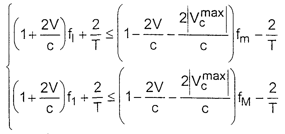
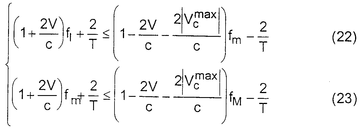
- the frequencies f m and f M are chosen to satisfy in in addition to relationships:
- ⁇ corresponds to the smallest interval separating the arithmetic sequence of reason p / q from the sequence of integers.
- a towed linear acoustic antenna is used to receive the reverberated signals.
- FIG. 4 a diagram similar to that of Figure 2, of the N signals transmitted in accordance with the invention.
- the invention proposes using signals coded according to codes, the spectrum of which has a so-called comb-line structure.
- Such a structure can be obtained by emitting a periodic broadband signal, or by direct synthesis in the spectral domain.
- the code transmitted consists of N "sub codes” weighted in cos 2 or "elementary patterns" broadband (FM.BPSK or other) identical, each of duration T / N, the whole sequence being weighted in amplitude over time T.
- Its spectrum, represented according to a frequency / direction diagram as in FIG. 1, will then have the appearance represented in FIG. 2.
- a comb of lines 201 is observed, each of width 4 / T (between the first zeros), spaced N / T, and having a strong spectral rejection between the lines.
- the set of lines covers a bandwidth B.
- the ratio of the reverberated intensity to the energy emitted is approximately equal to:
- V c radial speed of the target
- ⁇ 0 angular interval of overlap of the spectra. This formula is valid when V c ax > 2 V, which in practice is almost always the case.
- the invention therefore proposes to use a wide band comb code adapted to the speed of the wearer, regardless of the speed of the target.
- This broadband code of duration T and of bandwidth B, is such that the spacing between each line of its spectrum is equal to the frequency shoring of the reverberation associated with the line originating solely from the speed V of the carrier , as shown in FIG. 3, where the width of the pulses 301 has been exaggerated with respect to the interval 300 of variation of the copy. For 2 adjacent lines, this condition is written:
- FIG. 4 The diagram of the direction cos ⁇ as a function of the frequency under these conditions is represented in FIG. 4. It is noted that a single direction of reverberation 306 contributes to the interspectrum.
- the wide band code used is composed of N pulses each having a band of width B centered on the frequency f 0 .
- this condition corresponds to carrier speeds verifying the condition:
- i varies from 1 to a maximum value given by:
- reception processing of this broadband code can be done in a conventional manner by correlation with copies which correspond to all the possible "Doppler targets".
- the invention proposes, in a preferred embodiment, to use two conventional FP codes 401 and 411, each with the same energy as the broadband code, the frequencies of which are located symmetrically with respect to the spectrum of the broadband code.
- the frequencies f m and f M of these two codes are determined so as to ensure detection of the target, by one of the two codes, as soon as it is in zone C.
- these blind speeds correspond in all cases, taking into account the frequency spacing chosen for the broadband code, to targets in zone C (the worst cases correspond to a target coming from the rear with a radial speed of 2V , or a target coming from the front with a radial speed of -2V). It is therefore possible according to the invention to treat them with FP codes.
- the performances in zone C are then those of the FP mode, on the condition that the spectra of the different codes are sufficiently disjoint to be able to neglect mutual interactions.
- the different lines occupy the positions kN / T where k is an integer, and for certain elementary reasons (FM code for example), the decrease in the level of these lines is rather slow, so that the reverberation induced by the emission of the broadband code in the FP copy can be annoying.
- the spectrum of the FP copy intercepts one of the lines of the spectrum of the reverberation associated with the broadband code opposite the main lobe of the channel pointed at the target. This corresponds to a condition given by the formula:
- the 2 conditions (13) and (14) can occur simultaneously, which does not then ensure detection of the target by one of the 2 FP codes in zone C.
- the frequency values can be fixed at
- ⁇ ⁇ -, where ⁇ corresponds to the smallest interval separating the arithmetic sequence of reason p / q from the sequence of integers.
- the invention however still works, but with degraded performance, when only one of these 2 pure frequencies is used.
- a sonar with linear towed antenna was produced, the bandwidth available for transmission
- Each pulse of the broadband code therefore has a band equal to 480 Hz.
- T e T copies are generated by performing a Doppler shift of the broadband code transmitted with the Doppler parameters corresponding to the 2N / T interval.
- V for other speeds V , such as:
- the copies are generated by Doppler shift of the frequencies f m and f M with the corresponding Doppler parameters.
- the adapted filtering of the received signal is carried out simultaneously with all the copies thus generated and the normalization and detection processes known from the prior art are applied.
- the broadband code can be synthesized directly using the following formula:
Landscapes
- Physics & Mathematics (AREA)
- Engineering & Computer Science (AREA)
- Radar, Positioning & Navigation (AREA)
- Remote Sensing (AREA)
- Acoustics & Sound (AREA)
- Computer Networks & Wireless Communication (AREA)
- General Physics & Mathematics (AREA)
- Measurement Of Velocity Or Position Using Acoustic Or Ultrasonic Waves (AREA)
Abstract
Description


Claims


Priority Applications (5)
| Application Number | Priority Date | Filing Date | Title |
|---|---|---|---|
| EP99918028A EP1078280B1 (en) | 1998-05-15 | 1999-05-07 | Method for detecting mobile objects with active sonar |
| AU36098/99A AU769930B2 (en) | 1998-05-15 | 1999-05-07 | Method for detecting mobile objects with active sonar |
| DE69901102T DE69901102T2 (en) | 1998-05-15 | 1999-05-07 | METHOD FOR DETECTING MOVABLE GOALS BY AN ACTIVE SONAR |
| US09/674,505 US6314053B1 (en) | 1998-05-15 | 1999-05-07 | Method for detecting mobile objects with active sonar |
| NO20005783A NO332575B1 (en) | 1998-05-15 | 2000-11-15 | Process for detecting moving objects with active sonar |
Applications Claiming Priority (2)
| Application Number | Priority Date | Filing Date | Title |
|---|---|---|---|
| FR98/06179 | 1998-05-15 | ||
| FR9806179A FR2778748B1 (en) | 1998-05-15 | 1998-05-15 | METHOD OF DETECTING MOBILE OBJECTS BY ACTIVE SONAR |
Publications (1)
| Publication Number | Publication Date |
|---|---|
| WO1999060418A1 true WO1999060418A1 (en) | 1999-11-25 |
Family
ID=9526411
Family Applications (1)
| Application Number | Title | Priority Date | Filing Date |
|---|---|---|---|
| PCT/FR1999/001091 WO1999060418A1 (en) | 1998-05-15 | 1999-05-07 | Method for detecting mobile objects with active sonar |
Country Status (7)
| Country | Link |
|---|---|
| US (1) | US6314053B1 (en) |
| EP (1) | EP1078280B1 (en) |
| AU (1) | AU769930B2 (en) |
| DE (1) | DE69901102T2 (en) |
| FR (1) | FR2778748B1 (en) |
| NO (1) | NO332575B1 (en) |
| WO (1) | WO1999060418A1 (en) |
Families Citing this family (8)
| Publication number | Priority date | Publication date | Assignee | Title |
|---|---|---|---|---|
| US6052334A (en) * | 1998-08-04 | 2000-04-18 | Rowe-Deines Instruments | System and method for measuring wave directional spectrum and wave height |
| US7123544B1 (en) | 2004-05-24 | 2006-10-17 | The United States Of America As Represented By The Secretary Of The Navy | Assembly and method for determining speed of a supercavitating underwater vehicle |
| FR2872669B1 (en) * | 2004-07-02 | 2006-11-24 | Thales Sa | ATN NETWORK SIMULATION FOR THE TESTING OF TERMINAL EQUIPMENT APPLICATIONS IN CIVIL AIRCRAFT |
| FR2872919B1 (en) * | 2004-07-09 | 2006-09-29 | Thales Sa | FAST COHERENT TREATMENT FOR PERIODIC RATE SPECTRUM CODES |
| FR2900504B1 (en) | 2006-04-26 | 2009-11-20 | Thales Sa | METHOD FOR OPTIMIZING THE POWER SUPPLY OF A LINEAR TRANSMITTED TRANSMITTER ANTENNA FOR TRANSMITTING IN OMNIDIRECTIONAL MODE. |
| US7847925B2 (en) * | 2007-06-18 | 2010-12-07 | Teledyne Rd Instruments, Inc. | System and method of acoustic doppler beamforming |
| US8254208B2 (en) * | 2008-12-08 | 2012-08-28 | Teledyne Rd Instruments, Inc. | Multi-state beamforming array |
| JP5980113B2 (en) | 2009-05-27 | 2016-08-31 | テレダイン アールディー インスツルメンツ,インコーポレイテッド | System and method for determining wave characteristics from a mobile platform |
Citations (2)
| Publication number | Priority date | Publication date | Assignee | Title |
|---|---|---|---|---|
| FR2687226A1 (en) * | 1992-02-11 | 1993-08-13 | Thomson Csf | Method of detecting an underwater target with frequency diversity |
| JPH09159752A (en) * | 1995-12-12 | 1997-06-20 | Nec Corp | System for automatically detecting moving target |
Family Cites Families (3)
| Publication number | Priority date | Publication date | Assignee | Title |
|---|---|---|---|---|
| US35535A (en) * | 1862-06-10 | Improvement in lam p-chi mneys | ||
| US3732533A (en) * | 1966-04-04 | 1973-05-08 | Vadys Ass Ltd | Underwater explosive-acoustic transducer and systems |
| US5208785A (en) * | 1990-09-26 | 1993-05-04 | Rowe, Deines Instruments Incorporated | Broadband acoustic doppler current profiler |
-
1998
- 1998-05-15 FR FR9806179A patent/FR2778748B1/en not_active Expired - Lifetime
-
1999
- 1999-05-07 WO PCT/FR1999/001091 patent/WO1999060418A1/en active IP Right Grant
- 1999-05-07 AU AU36098/99A patent/AU769930B2/en not_active Expired
- 1999-05-07 EP EP99918028A patent/EP1078280B1/en not_active Expired - Lifetime
- 1999-05-07 DE DE69901102T patent/DE69901102T2/en not_active Expired - Lifetime
- 1999-05-07 US US09/674,505 patent/US6314053B1/en not_active Expired - Lifetime
-
2000
- 2000-11-15 NO NO20005783A patent/NO332575B1/en not_active IP Right Cessation
Patent Citations (3)
| Publication number | Priority date | Publication date | Assignee | Title |
|---|---|---|---|---|
| FR2687226A1 (en) * | 1992-02-11 | 1993-08-13 | Thomson Csf | Method of detecting an underwater target with frequency diversity |
| WO1993016398A1 (en) * | 1992-02-11 | 1993-08-19 | Thomson-Csf | Process for frequency diversity detection of an underwater target |
| JPH09159752A (en) * | 1995-12-12 | 1997-06-20 | Nec Corp | System for automatically detecting moving target |
Non-Patent Citations (4)
| Title |
|---|
| COX H: "Space-time processing for suppression of bottom reverberation", CA CONFERENCE ARTICLE, vol. 2, 30 October 1995 (1995-10-30) - 2 November 1995 (1995-11-02), Los Alamitos, CA, IEEE Comput. Soc. Press, USA, pages 1296 - 1299, XP002092784 * |
| COX H; HUNG LAI: "Geometric comb waveforms for reverberation suppression", CA CONFERENCE ARTICLE, vol. 2, 31 October 1994 (1994-10-31) - 2 November 1994 (1994-11-02), Los Alamitos, CA, USA, IEEE Comput. Soc. Press, pages 1185 - 1189, XP002092783 * |
| NIHAT M. BILGUTAY, JAFAR SANIIE: "Frequency agile minimum detector for target detection and clutter rejection", PROCEEDINGS OF THE NATIONAL COMMUNICATIONS FORUM, vol. 40, no. Part 2, 1986, Oak Brook, Illinois, USA, pages 1247 - 1252, XP002092785 * |
| PATENT ABSTRACTS OF JAPAN vol. 097, no. 010 31 October 1997 (1997-10-31) * |
Also Published As
| Publication number | Publication date |
|---|---|
| AU769930B2 (en) | 2004-02-12 |
| NO20005783D0 (en) | 2000-11-15 |
| EP1078280A1 (en) | 2001-02-28 |
| FR2778748B1 (en) | 2004-08-27 |
| DE69901102D1 (en) | 2002-05-02 |
| DE69901102T2 (en) | 2002-11-21 |
| NO332575B1 (en) | 2012-11-05 |
| AU3609899A (en) | 1999-12-06 |
| NO20005783L (en) | 2000-11-15 |
| FR2778748A1 (en) | 1999-11-19 |
| US6314053B1 (en) | 2001-11-06 |
| EP1078280B1 (en) | 2002-03-27 |
Similar Documents
| Publication | Publication Date | Title |
|---|---|---|
| EP0944844B1 (en) | Side scan sonar with synthetic antenna | |
| EP0870205A1 (en) | Method and system for sensing and locating a person, e.g. under an avalanche | |
| Groen et al. | Adaptive port-starboard beamforming of triplet sonar arrays | |
| EP1078280B1 (en) | Method for detecting mobile objects with active sonar | |
| CA1206584A (en) | Adaptive filter system of signals emitted by an active sonar for the suppression of correlated echoes | |
| EP2018579B1 (en) | Improved frontal sonar | |
| EP0458885A1 (en) | Method for increasing the image rate of a sonar and sonar for implementing such method | |
| EP0424239B1 (en) | Beam forming method for sonar | |
| WO2005069038A1 (en) | Device for avoiding obstacles for high-speed multi-hulled watercraft | |
| EP0580695B1 (en) | Movement compensation method for a sonar antenna | |
| EP1428038A1 (en) | Method of processing signals from a towed linear array | |
| EP1407292A1 (en) | Imaging sonar and a detection system using one such sonar | |
| EP2300847A1 (en) | Methods and systems for encoded broadcasting and antenna reception, particularly for radar | |
| EP1099958B1 (en) | Method and device to determine the shape of a linear antenna and resolve its directional ambiguity | |
| EP0626073B1 (en) | Process for frequency diversity detection of an underwater target | |
| EP0114547A2 (en) | Acoustic system with parametric multi-bundle antennas | |
| Ellis et al. | Comparison of range-dependent reverberation model predictions with array data from the 2013 Target and Reverberation Experiment | |
| FR2821164A1 (en) | DISTRIBUTED TRANSMISSION AND RECEPTION SYSTEM, IN PARTICULAR RADAR WITH SYNTHETIC TRANSMISSION AND BEAM FORMATION BY CALCULATION | |
| FR2731866A1 (en) | Electronically swept acoustic antennae for underwater ultrasonics | |
| FR2685782A1 (en) | Method of compensating for antenna movement in a sonar system | |
| FR2735873A1 (en) | Doppler log emitting modulated pulses with directional reception |
Legal Events
| Date | Code | Title | Description |
|---|---|---|---|
| AK | Designated states |
Kind code of ref document: A1 Designated state(s): AU CA JP NO US |
|
| AL | Designated countries for regional patents |
Kind code of ref document: A1 Designated state(s): AT BE CH CY DE DK ES FI FR GB GR IE IT LU MC NL PT SE |
|
| DFPE | Request for preliminary examination filed prior to expiration of 19th month from priority date (pct application filed before 20040101) | ||
| 121 | Ep: the epo has been informed by wipo that ep was designated in this application | ||
| WWE | Wipo information: entry into national phase |
Ref document number: 36098/99 Country of ref document: AU |
|
| WWE | Wipo information: entry into national phase |
Ref document number: 1999918028 Country of ref document: EP |
|
| WWE | Wipo information: entry into national phase |
Ref document number: 09674505 Country of ref document: US |
|
| WWP | Wipo information: published in national office |
Ref document number: 1999918028 Country of ref document: EP |
|
| WWG | Wipo information: grant in national office |
Ref document number: 1999918028 Country of ref document: EP |
|
| WWG | Wipo information: grant in national office |
Ref document number: 36098/99 Country of ref document: AU |