WO1996017429A1 - Commutatorless polyphase ac electric machine - Google Patents
Commutatorless polyphase ac electric machine Download PDFInfo
- Publication number
- WO1996017429A1 WO1996017429A1 PCT/CA1995/000651 CA9500651W WO9617429A1 WO 1996017429 A1 WO1996017429 A1 WO 1996017429A1 CA 9500651 W CA9500651 W CA 9500651W WO 9617429 A1 WO9617429 A1 WO 9617429A1
- Authority
- WO
- WIPO (PCT)
- Prior art keywords
- magnets
- stator
- rotor
- notches
- electric machine
- Prior art date
Links
Classifications
-
- H—ELECTRICITY
- H02—GENERATION; CONVERSION OR DISTRIBUTION OF ELECTRIC POWER
- H02K—DYNAMO-ELECTRIC MACHINES
- H02K29/00—Motors or generators having non-mechanical commutating devices, e.g. discharge tubes or semiconductor devices
- H02K29/03—Motors or generators having non-mechanical commutating devices, e.g. discharge tubes or semiconductor devices with a magnetic circuit specially adapted for avoiding torque ripples or self-starting problems
-
- H—ELECTRICITY
- H02—GENERATION; CONVERSION OR DISTRIBUTION OF ELECTRIC POWER
- H02K—DYNAMO-ELECTRIC MACHINES
- H02K1/00—Details of the magnetic circuit
- H02K1/06—Details of the magnetic circuit characterised by the shape, form or construction
- H02K1/12—Stationary parts of the magnetic circuit
- H02K1/16—Stator cores with slots for windings
- H02K1/165—Shape, form or location of the slots
-
- H—ELECTRICITY
- H02—GENERATION; CONVERSION OR DISTRIBUTION OF ELECTRIC POWER
- H02K—DYNAMO-ELECTRIC MACHINES
- H02K1/00—Details of the magnetic circuit
- H02K1/06—Details of the magnetic circuit characterised by the shape, form or construction
- H02K1/22—Rotating parts of the magnetic circuit
- H02K1/27—Rotor cores with permanent magnets
- H02K1/2786—Outer rotors
- H02K1/2787—Outer rotors the magnetisation axis of the magnets being perpendicular to the rotor axis
- H02K1/2789—Outer rotors the magnetisation axis of the magnets being perpendicular to the rotor axis the rotor consisting of two or more circumferentially positioned magnets
- H02K1/2791—Surface mounted magnets; Inset magnets
- H02K1/27915—Magnets shaped to vary the mechanical air gap between the magnets and the stator
-
- H—ELECTRICITY
- H02—GENERATION; CONVERSION OR DISTRIBUTION OF ELECTRIC POWER
- H02K—DYNAMO-ELECTRIC MACHINES
- H02K21/00—Synchronous motors having permanent magnets; Synchronous generators having permanent magnets
- H02K21/12—Synchronous motors having permanent magnets; Synchronous generators having permanent magnets with stationary armatures and rotating magnets
Definitions
- the present invention relates to a polyphase alternating current electric machine having a stator frame and a rotor frame.
- the stator's magnetic circuit is made up of metal strips with a non-linear magnetization curve. This curve shows a high initial permeability until it reaches a certain level of magnetic force where it falls to a value equivalent to the air permeability.
- the distribution of the flux density in the metal strips results from the addition of the strength of the magnetic fields produced by the current in the conductors and by the magnets, taking into account the magnetization curve.
- the flux density increases proportionally with the increase of the current in the conductors, thereby increasing the resulting torque.
- the magnetic field resulting from the sum of the two sources is kept below the saturation threshold in all the regions of the magnetic circuit.
- the current in the conductors can be increased to a level where the total magnetic force goes beyond the saturation threshold and where the flux density no longer follows proportionally. This phenomenon occurs in regions of the magnetic circuit where the two magnetic forces are cumulative.
- the torque is subject to distortion, stops increasing linearly, and tends to saturate with increasing current in the conductors.
- the fluctuation in flux density in the metal lamellae of the stator is a factor that produces losses related to hysteresis effects and eddy currents. These losses are proportional to the harmonics contained in the flux density.
- the trigger torque produced by the attraction between each of the magnets and the parts in protrusion during rotation of the rotor must be taken into account.
- the torque harmonics generated by the product of the conductor currents with the magnetic field of the magnets add to the expansion torque.
- the percentage of filling of the space available in the slots by the copper conductors influences the weight of the machine and the thermal conductivity between the copper conductors and the steel.
- the geometry of the magnetic circuit must be used to channel the flux density as much as possible without however reaching saturation, thereby minimizing the total weight of the machine.
- the protruding parts of the stator must have curved ends partially covering the notches in order to allow the minimum opening necessary to insert the conductors one by one into the corresponding notch.
- the curved ends must have a relatively uniform thickness in order to to prevent saturation by the magnetic field of the magnets.
- each notch of the stator reduces the trigger torque.
- This oblique notch induces a progressive phase shift of the expansion torque along the length of each of the projecting parts of the stator so that, overall, all the harmonics are canceled.
- the oblique notch was used in the apparatus described in US Patent No. 5,327,034. This solution may seem simple, but from a practical point of view, it increases the complexity of the construction. In addition, this solution is difficult to achieve in the case where the axial length of the stator along the axis of rotation is relatively short. Thanks to the curved ends, it is possible to channel a substantial part of the magnetic field while minimizing the quantity of magnets necessary to produce a magnetic field around the conductors.
- each harmonic induces an eddy current which generates a loss which is added to the total loss of the machine. These losses are added to the losses due to the fundamental component.
- shape of the flux picked up by the windings depends on the way in which the stator has been wound. With a single winding, that is say a phase by notch by pole, there are presence of flux harmonics which cause a torque ripple if the currents in the phases are sinusoidal. It is always possible to reduce the ripple by increasing the number of notches per pole and by using windings which are nested one in the other to filter the harmonics of flux but, in this case, the complexity of l assembly is increased. Finally, the y / p ratio limits the possible geometries.
- the object of what is proposed in this document is to reduce the trigger torque.
- the proportion of the number of rotor poles to the number of stator poles causes division.
- the torque resulting from the sum of the torques induced by each of the rotor poles on the stator is uniform.
- the problems of loss in the metal strip associated with the flow harmonics are still present.
- the currents in the windings must be trapezoidal. These current harmonics produce an additional loss due to the skin effect (kelvin effect). It should be noted that this machine also uses projecting parts with notches provided with ends curved.
- the machine described in this patent is of the direct current type and uses a stator with poles having permanent magnets formed so as to reduce the expansion torque when the rotor armature rotates.
- the machine has a rotor with projecting parts and notches without curved ends.
- the stator poles cover a peripheral part of the rotor with a constant air gap.
- the machine's expansion torque results from the variation in permeability induced by the succession of notches and the protruding parts of the rotor passing in front of each of the stator poles.
- a pole produces an alternating trigger torque with positive and negative maxima having the same magnitude.
- the poles are separated from each other by 180 ° electric.
- the positive and negative maxima of the expansion torque produced by each of the poles contribute to the increase in the overall expansion torque. It is possible to phase-shift one pole out of two by a given angle so that the positive maximum of half of the poles corresponds to the negative maximum of the other half. Thus, the sum of the relaxation couples produced by one half of the poles cancels the sum of the relaxation couples produced by the other half.
- the geometry of the proposed poles consists in removing part of each of the poles. The removed parts are adjacent from one pole to another. Thus, it is possible to obtain the phase shift of a pole without physically phase shifting the entire pole. Thanks to this method, the construction of the engine is simplified. However, due to the flat profile of the poles, flux harmonics are produced along the magnetic paths, which increases losses in the iron.
- a first object of the present invention is to propose an electric machine with polyphase alternating current without collector having a curve of the torque compared to the current which is linear inside a wide current band.
- a second object of the present invention is to provide an electrical machine with polyphase alternating current without collector which has low losses due to the harmonic distortion of the flux density in the armature of the stator.
- a third object of the present invention is to provide an electrical machine with polyphase alternating current without collector having a low expansion torque between the armature of the rotor and the armature of the stator, under load and at no load.
- the present invention provides a polyphase alternating current electric machine without collector comprising: a stator frame having a surface provided with notches and parallel projecting parts arranged alternately, each of said notches having an opening on said surface, each of said openings being substantially as wide as the widest part of the corresponding notch; and a rotor frame having a surface provided with permanent magnetizing means having respective surface sections facing said notches and protrusions, each of said surface sections facing a number of said notches corresponding to a number of phases of said machine , all of said surface sections of said magnetization means producing a magnetic flux density having a component of mean amplitude B r ( ⁇ ) perpendicular to the corresponding surface of the stator, which is substantially defined by the following equation:
- ⁇ is an angular position in radians with respect to a reference position on said rotor armature;
- B r ( ⁇ ) is said component of mean amplitude at said angular position ⁇ ;
- L ( ⁇ ) is a distance apart between said protrusions and said surface of said rotor frame at said angular position ⁇ ;
- M r ( ⁇ ) is a residual induction component of said magnetization means at said angular position ⁇ , M r ( ⁇ ) being perpendicular to the corresponding surface of the stator armature, M r ( ⁇ ) alternating according to a corresponding period at 4 ⁇ r / K;
- K is an even number representing all of said surface sections;
- C is an arbitrary constant;
- the present invention also provides a method of operating a polyphase alternating current electric machine without a collector, comprising the steps of: magnetically coupling a stator frame provided with windings with a rotor frame, the stator frame having a surface provided with recesses and parallel projecting parts arranged alternately, each of said notches having an opening on said surface, each of said openings being substantially as wide as the widest part of the corresponding notch, the rotor frame having a surface provided with permanent magnetization means having respective surface sections facing said notches and projecting parts, each of said surface sections facing a number of said notches corresponding to a number of machine phases, all of said surface sections said magnetization means producing a magnetic flux density ic having a component of mean amplitude B r ( ⁇ ) perpendicular to the corresponding surface of the stator armature, which is substantially defined by the following equation:
- ⁇ is an angular position in radians with respect to a reference position on said rotor frame
- B r ( ⁇ ) is said component of mean amplitude at said angular position ⁇
- Iv ( ⁇ ) is a distance apart between said protrusions and said surface of said rotor frame at said angular position ⁇
- M,. ( ⁇ ) is a component of the residual induction of said magnetization means at said angular position ⁇ , M,. ( ⁇ ) being perpendicular to the corresponding surface of the stator armature, M,.
- Figure 1 is a partial side view in section of the stator and rotor armatures of a polyphase alternating current electric machine without collector according to a first preferred embodiment of the invention
- Figure 2 is a partial side view in section of the stator and rotor armatures of a polyphase alternating current electric machine without collector according to a second preferred embodiment of the invention
- Figure 3 is a partial side view in section of the stator and rotor armatures of a polyphase alternating current electric machine without collector according to a third preferred embodiment of the present invention
- Figure 4 is a partial side view in section of the stator and rotor armatures of a polyphase alternating current electric machine without collector according to a fourth preferred embodiment of the present invention
- Figure 5 is a partial side view in section of the stator and rotor armatures of a polyphase alternating current electric machine without collector according to a fifth preferred embodiment of the present invention
- Figure 6 is a partial side view in section of the stator and rotor armatures of a polyphase alternating current electric machine without collector according to a sixth preferred embodiment of the present invention
- FIG. 7 is a partial side view in section of the stator and rotor armatures of a polyphase alternating current electric machine without collector according to a seventh preferred embodiment of the present invention.
- FIG. 8 is a partial side view in section of the stator and rotor armatures of a polyphase alternating current electric machine without collector according to an eighth preferred embodiment of the present invention.
- FIG. 9 is a partial side view in section of the stator and rotor armatures of a polyphase alternating current electric machine without collector according to a ninth preferred embodiment of the present invention.
- Figure 10 is a partial cross-sectional view along lines X-X shown in Figure 1 according to a preferred embodiment of the invention
- Figure 11 is a partial cross-sectional view along the lines X-X shown in Figure 1 according to another preferred embodiment of the invention.
- FIG. 12 is a diagram showing the relationship between the current I and the torque T when the machine is in operation.
- FIG. 1 shows a partial side view in section of the stator and rotor armatures of a polyphase alternating current electric machine without collector.
- This machine comprises a stator frame 2 having a surface provided with notches 8 and projecting parts 7 parallel and arranged alternately.
- Each of the notches 8 has an opening 40 on the surface of the stator frame 2.
- Each of the openings 40 is substantially as wide as the widest part of the corresponding notch 8.
- the machine also comprises a rotor frame 1 having a surface 44 provided with permanent magnetization means 3 having respective surface sections 42 facing the notches 8 and the protruding parts 7.
- Each of these surface sections 42 faces a number of slots 8 corresponding to the number of machine phases.
- each of the surface sections 42 faces three notches 8. It is therefore a three-phase machine.
- All the surface sections 42 of the magnetization means 3 produce a magnetic flux density having a component of mean amplitude Br ( ⁇ ) perpendicular to the corresponding surface of the stator 2, which is substantially defined by the following equation:
- ⁇ is an angular position in radians with respect to a reference position on the rotor armature 1.
- B r ( ⁇ ) is the component of mean amplitude at the angular position ⁇ .
- L v ( ⁇ ) is a distance of difference between the projecting parts 7 and the surface 44 of the rotor frame 1 at the angular position ⁇ .
- .. ( ⁇ ) is the residual induction component of the magnetization means 3 at the angular position ⁇ .
- M r ( ⁇ ) is perpendicular to the corresponding surface on stator 2.
- M r ( ⁇ ) alternates according to a period corresponding to 4 ⁇ / K.
- K is an even number representing all the surface sections 42 and C is an arbitrary constant.
- the stator frame 2 has a cylindrical shape.
- the surface provided with notches 8 and parallel projecting parts 7 form the external surface of the stator frame 2.
- the rotor frame 1 has a cylindrical shape.
- the surface 44 provided with permanent magnetization means forms an internal surface of the rotor frame 1.
- the component of average amplitude B r ( ⁇ ) is a radial component.
- Each of the notches 8 has a rectangular section.
- the permanent magnetization means comprise a series of permanent magnets 3 made of a homogeneous material. Each of these magnets 3 has a thickness, relative to the angular position ⁇ , determined substantially by L a ( ⁇ ).
- Each of the protruding parts 7 ends in a square manner.
- the operating method of the polyphase alternating current electric machine without collector illustrated in FIG. 1 comprises the steps of magnetically coupling the stator armature 2 provided with the windings 6 with the rotor armature 1, and supplying power the windings 6 of the stator 2.
- the rotor armature 1 is magnetically coupled to the stator armature 2, while making it possible to reduce the losses due to the density of magnetic flux in the stator armature 2, to have a curve of the torque compared to the current which is linear for a wide band of current and to reduce the expansion torque between the stator armature 2 and the rotor armature 1.
- the cylindrical rotor 1 comprises a cylinder head 4 made of steel and a number K of magnets 3 mounted on the internal wall of the cylinder head 4, K being an even integer.
- the cylinder head 4 of the rotor 1 is separated from the cylindrical stator 2 by a distance - -
- the stator 2 is made of magnetic metal strips 5 forming a series of projecting parts 7 and non-oblique notches 8. These notches 8 open in the direction of the rotor 1.
- conductors 6 of rectangular section are mounted in the notches 8. All the conductors 6 mounted in the same notch 8 correspond to the same phase.
- the number of phases can vary from two to N, N being an integer greater than two.
- the stator 2 has N notches 8 for each magnet 3 of the rotor 1.
- the total number of notches 8 or projecting parts 7 is equal to N "K.
- each magnet 3 has a high uniform intrinsic coercive force inside the material and a magnetic permeability equal to that of air.
- the cylinder head 4 and the metal strips 5 are made of a material having a high magnetic permeability.
- the magnetization curve of each of the cylinder heads 4 and of the metal strips 5 is non-linear and reaches a saturation threshold at the point where the permeability decreases to a value equal to that of air.
- Each of the magnets 3 has an arc-shaped profile 9 harmonizing with the circular internal wall of the rotor 1.
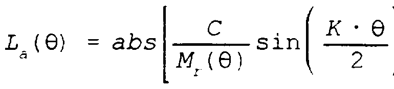
- Each of the magnets 3 also has a second opposite profile 10 defined so that its radial thickness L a is defined by:
- ⁇ is an angular position in radians with respect to a reference position on the rotor 1.
- L a ( ⁇ ) is the radial thickness of the magnet 3 at an angular position ⁇ .
- M r ( ⁇ ) is the radial component of residual induction of the magnet 3 at the angular position ⁇ , and alternates according to a period corresponding to 4 ⁇ / K.
- K is an even number representing all the magnets 3 on the periphery of the rotor 1.
- C is a constant.
- the flux density channeled by a projecting part 7 is substantially produced by the portion of magnets contained in the volume 11 located between the end of the corresponding projecting part 7 and the cylinder head 4.
- the average amplitude of the radial component of the flux density Br ( ⁇ ) in a section of volume 11 is defined by:
- B r ( ⁇ ) is sinusoidal because M r ( ⁇ ) alternates 180 ° from a magnet to the other. It is possible to define B r ( ⁇ ) by:
- B r ( ⁇ ) The shape of B r ( ⁇ ) is sinusoidal when the rotor 1 rotates.
- the equation is valid provided that the machine is in operation in the linear part of the steel magnetization curve.
- L a ( ⁇ ) varies according to a sine with respect to the angular position ⁇ because M r ( ⁇ ) is considered to be constant.
- the current flowing through the conductors 6 produces a magnetic field which is added to that produced by the magnets 3.
- the total flux density corresponds to the vector sum of the flux density produced by the magnets 3 and the flux density produced by the currents through the conductors 6. As illustrated in FIG.
- the present invention allows to obtain a rotary machine whose torque curve with respect to the current is linear for a current band (a) which is wider than that of similar machines described in the prior art.
- the torque obtained with the machine according to the present invention is the tangential component of the force produced at the radius of the air gap. This force results from the vector product of the currents in the conductors with the magnetic field produced by the magnets 3.
- the phase current in the notches 8 alternates with the flow channeled by the projecting parts 7 to produce a torque in the same direction.
- the vector product is proportional to the currents through the conductors 6.
- the magnetic field produced by the magnets 3 is added to that produced by the currents through the conductors 6. By increasing the current, a saturation of the flux density is produced in the zones where the sum of the fields is cumulative.
- the open notches 8 of the stator 2 make it possible to use conductors of substantially rectangular section for the windings.
- the sections of the notches can therefore be smaller and the length of the projections to channel the flow can be shorter. Consequently, the weight of a machine making it possible to obtain a torque similar to that obtained by the machines described in the prior art is smaller.
- the flux density in a specific location inside one of the projections 7 is proportional to B r ( ⁇ ).
- the inner strip of the metal strips 5 of the stator 2 is used as a return path for the magnetic field induced in the corresponding projecting parts 7.
- the density channelized flow is the sum of the sinusoidal flows, so the sum is also sinusoidal.
- the losses associated with harmonics other than the fundamental component, inside the metal strips 5 of the stator 2 are negligible compared to the loss due to the fundamental component. As a result, the machine operates with reduced losses in the iron.
- the present invention makes it possible to obtain a rotary machine which has, in operation, a low ripple torque under load or when empty.
- This result can be explained as follows.
- the rotation of the rotor 1 relative to the stator 2 produces a force of attraction between the magnets 3 and the projecting parts 7.
- This force of attraction is associated, when the machine is running, with the variation of energy which is stored in the magnetic field contained substantially inside the volumes 11 of air and magnets between each projecting part 7 and the head of the cylinder 4.
- the tangential component of this attraction force for each projection 7 is added to the torque.
- the couple T is defined as follows:
- W is the energy contained inside volume 11 and is defined by:
- R le is the internal radius of the cylinder head 4 of the rotor 1
- the couple T is the derivative of W with respect to ⁇ .
- the torque T is defined as follows:
- the trigger torque on each of the projecting parts 7 is therefore sinusoidal and periodic according to l / (2 ⁇ K).
- the total expansion torque when the machine is empty is the sum of the expansion couples acting on each of the protruding parts 7 of the stator 2. Since there are N * K protruding parts 7 on all of the stator 2, the total expansion torque T r is equal to:
- the flux density produced by the magnets 3 in the projecting parts 7 of the stator is sinusoidal.
- the magnetic flux surrounded by the coils forming a phase of the machine corresponds to the sum of the flows channeled by the projecting parts wound by the corresponding windings. This sum of flows is also sinusoidal.
- the sum of the torques developed by each of the phases is constant for sinusoidal phase currents, which are similarly phase-shifted with respect to the channeled flow. Consequently, the machine does not present a trigger torque in operation.
- a sinusoidal current reduces the losses of joules in copper, associated with the kelvin effect (skin effect). The loss is minimal when the harmonic content in the current inside the copper has only one component.
- FIG. 2 shows an electrical machine with polyphase alternating current without collector which is preferably characterized in that each of the projecting parts 7 has a square end and that each of the magnets has a truncated end.
- the volume of magnetic material that has been truncated at each end a magnet 3 is added near this same truncated end so as to increase its thickness.
- each of the magnets 3 has thicker truncated ends and about the same amount of magnetic material as if it did not have truncated ends. Thanks to this modification, it is possible to produce magnets whose ends are less fragile than those of non-truncated magnets.
- These truncated magnets are also easier to mount on the cylinder head 4 of the rotor 1. The consequences on the magnetic performance of the flux density are negligible.
- Figure 3 shows an electric machine with polyphase alternating current without collector which is preferably characterized in that each of the projecting parts 7 has a rounded end and that each of the magnets has truncated ends.
- the ends of the magnets 3 have been thickened by adding thereto respectively the volume of magnetic material which has been truncated. Thanks to the rounded ends 28 of the projecting parts 7, it is possible to eliminate the funneling effect of the flux density, which produces a saturation of flow in the projecting parts 7. This funneling effect has the effect increase the amplitude of the harmonic components when the projecting parts have square ends. Also, the magnetic flux leakage produced by the currents in the conductors is reduced.
- the flow channeled in the projecting parts 7 is produced by magnets having a higher magnetization to compensate for the rounded ends of the projecting parts 7.
- FIG. 4 shows a polyphase alternating current electric machine without collector, preferably characterized in that the stator armature 2 has an internal surface 48 having recesses 30 substantially aligned with the respective projecting parts 7. Also, each of the protrusions 7 has a rounded end and each of the magnets has truncated ends. As for the embodiment shown in FIG. 2, the ends of the magnets 3 are thickened by adding thereto respectively the volume of truncated magnetic material.
- the rotor frame 1 has an outer surface 50 having recesses 29 substantially aligned with central portions of the respective magnets 3.
- Another preferred object of the present invention is to provide a machine having a reduced weight. This reduction in weight is obtained by removing zones where the density of the magnetic flux is low, as illustrated in FIG. 4. Steel has been removed in zones 29 and 30 where the maximum flux density is low. Thus, the flux density in the remaining portions adjacent to zones 29 and 30 increases to a level similar to that which occurs in the machine in general.
- FIG. 4 makes it possible to achieve another object of the present invention, that is, that of obtaining an electric machine with polyphase alternating current without collector, characterized by a geometry of the stator's magnetic circuit which is smaller. Therefore with this embodiment, it is possible to reduce the total weight of the electric machine.
- FIG. 5 shows a polyphase alternating current electric machine without collector which is preferably characterized in that the rotor frame 1 has a cylindrical outer surface 50.
- Each of the projecting parts 7 has a rounded end and the inner surface 44 of the rotor armature 1 is provided with inwardly curved housings to receive the permanent magnets 3, respectively.
- FIG. 6 shows a polyphase alternating current electric machine without collector which is preferably characterized in that the rotor armature 1 has a cylindrical external surface 50. Each of the parts in projection has a rounded end. Each of the magnets 3 has truncated ends. As for the embodiment shown in FIG. 2, the ends of the magnets 3 are thickened by adding thereto respectively the volume of truncated magnetic material.
- the internal surface 44 of the rotor frame 1 is provided with housings curved inwards to receive the permanent magnets 3 respectively.
- FIG. 7 shows a polyphase alternating current electric machine without collector, preferably characterized in that the stator armature 2 has a corrugated inner surface 48 defining recesses 30 substantially aligned with the respective projecting parts 7.
- Each of the notches ends with a rounded bottom.
- Each of the protrusions 7 has a rounded end and each of the magnets has truncated ends.
- the ends of the magnets 3 are thickened by adding thereto respectively the volume of truncated magnetic material.
- 8 shows a polyphase alternating current electric machine without collector which is preferably characterized in that the stator frame 2 has an internal surface 48 and is provided with transverse cavities 52 substantially aligned with the respective projecting parts 7.
- Each of the cavities 52 is located midway between a lower end of the corresponding projecting part 7 and the internal surface 48 of the stator frame 2.
- Each of the cavities 52 has a substantially triangular shape with an apex 54 facing the corresponding projecting part 7.
- Each of the notches 8 ends in a rounded bottom.
- Each of the protruding parts 7 has a rounded end and each of the magnets 3 has truncated ends.
- each end of the magnets 3 is thickened by adding thereto respectively the volume of truncated magnetic material.
- FIG. 9 shows an electrical machine with polyphase alternating current without collector which is preferably characterized by the fact that each of the projecting parts 7 has a square end and each of the magnets 3 has truncated ends.
- each end of the magnets 3 is thickened by adding thereto respectively the volume of truncated magnetic material.
- the rotor frame 1 has an outer surface 50 having recesses 29 substantially aligned with central portions of the respective magnets 3.
- Figures 10 and 11 each show a polyphase alternating current electric machine without collector which is preferably characterized in that the stator frame 2 is made of a series of adjacent metal strips 54 having peripheral parts forming the parts projecting 7. These peripheral parts have a thickness tapered towards the periphery of the metal strips.
- the peripheral parts of the stator illustrated in FIG. 10 are identical and have the same symmetrical taper while those illustrated in FIG. 11 have a non-symmetrical taper.
- each of the metal or stator sheets forming each of the protruding parts is not uniform but rather tapered from the base of the corresponding protruding part towards its end, which allows to make the magnetic flux density along each of the projecting parts more uniform.
- the magnets are used to produce a magnetic field in a rotary machine provided with a group of conductors excited by alternating, polyphase and sinusoidal currents.
- the magnets are profiled magnets made of a homogeneous material and are mounted on the internal wall of the cylindrical rotor so as to face a series of projections and notches, the notches having openings without curved ends.
- a magnetic field of sinusoidal shape is produced in the polar parts to reduce the harmonic components, excluding the fundamental, and thus reduce the losses. Consequently, a high torque and a very low trigger torque are obtained. The weight of the pole pieces is also reduced.
Landscapes
- Engineering & Computer Science (AREA)
- Power Engineering (AREA)
- Permanent Field Magnets Of Synchronous Machinery (AREA)
- Iron Core Of Rotating Electric Machines (AREA)
- Permanent Magnet Type Synchronous Machine (AREA)
- Brushless Motors (AREA)
Abstract
Description


Claims


Priority Applications (5)
| Application Number | Priority Date | Filing Date | Title |
|---|---|---|---|
| EP95937737A EP0795229A1 (en) | 1994-12-02 | 1995-11-15 | Commutatorless polyphase ac electric machine |
| AU38656/95A AU3865695A (en) | 1994-12-02 | 1995-11-15 | Commutatorless polyphase ac electric machine |
| BR9508702A BR9508702A (en) | 1994-12-02 | 1995-11-15 | Brushless multiphase electric AC machine and method for its operation |
| JP8517974A JPH11500897A (en) | 1994-12-02 | 1995-11-15 | Polyphase brushless AC electric machine |
| MX9700858A MX9700858A (en) | 1994-12-02 | 1995-11-15 | Commutatorless polyphase ac electric machine. |
Applications Claiming Priority (2)
| Application Number | Priority Date | Filing Date | Title |
|---|---|---|---|
| US353,241 | 1990-03-20 | ||
| US08/353,241 US5753991A (en) | 1994-12-02 | 1994-12-02 | Multiphase brushless AC electric machine |
Publications (1)
| Publication Number | Publication Date |
|---|---|
| WO1996017429A1 true WO1996017429A1 (en) | 1996-06-06 |
Family
ID=23388299
Family Applications (1)
| Application Number | Title | Priority Date | Filing Date |
|---|---|---|---|
| PCT/CA1995/000651 WO1996017429A1 (en) | 1994-12-02 | 1995-11-15 | Commutatorless polyphase ac electric machine |
Country Status (12)
| Country | Link |
|---|---|
| US (1) | US5753991A (en) |
| EP (1) | EP0795229A1 (en) |
| JP (1) | JPH11500897A (en) |
| CN (1) | CN1157675A (en) |
| AR (1) | AR000493A1 (en) |
| AU (1) | AU3865695A (en) |
| BR (1) | BR9508702A (en) |
| CA (1) | CA2191128A1 (en) |
| MX (1) | MX9700858A (en) |
| TR (1) | TR199501515A2 (en) |
| TW (1) | TW280964B (en) |
| WO (1) | WO1996017429A1 (en) |
Cited By (1)
| Publication number | Priority date | Publication date | Assignee | Title |
|---|---|---|---|---|
| US11002566B2 (en) | 2007-06-27 | 2021-05-11 | Brooks Automation, Inc. | Position feedback for self bearing motor |
Families Citing this family (49)
| Publication number | Priority date | Publication date | Assignee | Title |
|---|---|---|---|---|
| JPH09308218A (en) * | 1996-05-10 | 1997-11-28 | Canon Inc | Linear motor, stage system and exposure device using it |
| SE512784C2 (en) | 1998-04-21 | 2000-05-15 | Hoeganaes Ab | Induktionsmaskinstator |
| JP2000166152A (en) | 1998-11-20 | 2000-06-16 | Mitsubishi Electric Corp | Stator of ac generator for vehicle and its manufacture |
| JP3559181B2 (en) * | 1998-11-30 | 2004-08-25 | 三菱電機株式会社 | Motor for electric power steering system |
| TW443667U (en) * | 1999-10-13 | 2001-06-23 | Delta Electronics Inc | Improved magnetic structure |
| US6140736A (en) * | 1999-10-22 | 2000-10-31 | Hsu; Chun-Pu | Anti-loosening outer rotor means for high-torque outer-rotor type electric motor |
| JP2002010606A (en) * | 2000-06-20 | 2002-01-11 | Honda Motor Co Ltd | Outer rotor brushless dc motor |
| JP2002101628A (en) * | 2000-09-22 | 2002-04-05 | Hitachi Ltd | Permanent magnet rotating electric machine |
| US7245054B1 (en) | 2000-11-01 | 2007-07-17 | Emerson Electric Co. | Permanent magnet electric machine having reduced cogging torque |
| US6707209B2 (en) | 2000-12-04 | 2004-03-16 | Emerson Electric Co. | Reduced cogging torque permanent magnet electric machine with rotor having offset sections |
| US6597078B2 (en) * | 2000-12-04 | 2003-07-22 | Emerson Electric Co. | Electric power steering system including a permanent magnet motor |
| JP2003092863A (en) * | 2001-09-20 | 2003-03-28 | Nissan Motor Co Ltd | Permanent magnet embedded synchronous motor |
| US6784582B1 (en) | 2001-11-19 | 2004-08-31 | Valeo Electrical Systems, Inc. | Magnet shaping and pole concentration for reduction of cogging torque in permanent magnet motors |
| EP1458080B1 (en) * | 2001-12-20 | 2017-03-01 | Mitsubishi Denki Kabushiki Kaisha | Permanent magnet type dynamo-electric machine and wind power generation-use permanent magnet type synchronous generator |
| US6844645B2 (en) * | 2002-11-08 | 2005-01-18 | Wavecrest Laboratories, Llc | Permanent magnet motor rotor having magnetic permeable material for enhanced flux distribution |
| TWI223488B (en) * | 2003-03-25 | 2004-11-01 | Delta Electronics Inc | Motor rotor and manufacture method thereof |
| US7262536B2 (en) * | 2003-08-11 | 2007-08-28 | General Motors Corporation | Gearless wheel motor drive system |
| US20050035678A1 (en) * | 2003-08-11 | 2005-02-17 | Ward Terence G. | Axial flux motor mass reduction with improved cooling |
| US7332837B2 (en) * | 2003-08-11 | 2008-02-19 | General Motors Corporation | Cooling and handling of reaction torque for an axial flux motor |
| DE102004044700B4 (en) * | 2004-09-15 | 2008-04-24 | Siemens Ag | synchronous machine |
| JP2006174692A (en) * | 2004-11-19 | 2006-06-29 | Nippon Densan Corp | Brushless motor |
| JP4797431B2 (en) * | 2005-05-02 | 2011-10-19 | 三菱電機株式会社 | Permanent magnet type motor |
| DE102006006882A1 (en) * | 2005-11-21 | 2007-05-24 | Robert Bosch Gmbh | Electric machine and rotor for an electric machine |
| JP5448314B2 (en) * | 2006-08-30 | 2014-03-19 | 信越化学工業株式会社 | Permanent magnet and permanent magnet rotating machine |
| WO2008031080A2 (en) * | 2006-09-08 | 2008-03-13 | Gm Global Technology Operations, Inc. | Vehicular wheel assembly |
| US8283813B2 (en) | 2007-06-27 | 2012-10-09 | Brooks Automation, Inc. | Robot drive with magnetic spindle bearings |
| US8659205B2 (en) * | 2007-06-27 | 2014-02-25 | Brooks Automation, Inc. | Motor stator with lift capability and reduced cogging characteristics |
| KR101660894B1 (en) | 2007-06-27 | 2016-10-10 | 브룩스 오토메이션 인코퍼레이티드 | Multiple dimension position sensor |
| US9752615B2 (en) * | 2007-06-27 | 2017-09-05 | Brooks Automation, Inc. | Reduced-complexity self-bearing brushless DC motor |
| US8823294B2 (en) | 2007-06-27 | 2014-09-02 | Brooks Automation, Inc. | Commutation of an electromagnetic propulsion and guidance system |
| CN101801817B (en) | 2007-07-17 | 2015-07-22 | 布鲁克斯自动化公司 | Substrate processing apparatus with motors integral to chamber walls |
| US20090072648A1 (en) * | 2007-09-18 | 2009-03-19 | Li Mei-Han | Outward turning motor rotor for a ceiling fan |
| US8129880B2 (en) * | 2007-11-15 | 2012-03-06 | GM Global Technology Operations LLC | Concentrated winding machine with magnetic slot wedges |
| JP2010022088A (en) * | 2008-07-08 | 2010-01-28 | Kokusan Denki Co Ltd | Magnet rotation type rotary electric machine |
| US7741750B1 (en) * | 2008-12-29 | 2010-06-22 | Tesla Motors, Inc. | Induction motor with improved torque density |
| JP5210150B2 (en) * | 2008-12-29 | 2013-06-12 | 株式会社日立産機システム | Permanent magnet type rotating electrical machine, elevator apparatus, and manufacturing method of permanent magnet type rotating electrical machine |
| JP2010178442A (en) * | 2009-01-28 | 2010-08-12 | Hitachi Ltd | Outer rotation type permanent magnet rotary electric machine and elevator apparatus using same |
| JP2010178493A (en) * | 2009-01-29 | 2010-08-12 | Mitsuba Corp | Outer rotor type brushless motor |
| US8035270B2 (en) | 2009-06-30 | 2011-10-11 | American Axle & Manufacturing, Inc. | Wheel motor |
| US8069555B2 (en) * | 2010-02-18 | 2011-12-06 | Tesla Motors, Inc. | Manufacturing method utilizing a dual layer winding pattern |
| EP2378635A1 (en) * | 2010-04-13 | 2011-10-19 | Siemens Aktiengesellschaft | Electrical machine and permanent-magnet |
| EP2388891A1 (en) * | 2010-05-19 | 2011-11-23 | Siemens Aktiengesellschaft | Generator with compact single turn wave winding and wind turbine |
| EP2403108A1 (en) * | 2010-06-29 | 2012-01-04 | Siemens Aktiengesellschaft | Wind turbine generator and method of assembly of a wind turbine generator |
| US20120025655A1 (en) * | 2010-07-29 | 2012-02-02 | System General Corporation | Motor rotor and motor having the motor rotor |
| JP6095267B2 (en) * | 2012-02-24 | 2017-03-15 | 株式会社クリーンクラフト | Three-phase permanent magnet synchronous motor |
| CN105305734B (en) * | 2015-10-22 | 2018-10-09 | 江苏大学 | The harmonic wave note of fault tolerant permanent magnet machine cuts method |
| JP2018143043A (en) * | 2017-02-28 | 2018-09-13 | 日本電産株式会社 | motor |
| CN108599427A (en) * | 2018-04-20 | 2018-09-28 | 宁波大叶园林设备股份有限公司 | A kind of brushless motor using 12 slot, ten extremely low cogging torque structure |
| CN212784936U (en) * | 2020-08-24 | 2021-03-23 | 深圳市大疆创新科技有限公司 | Magnetic part, motor and movable platform |
Citations (3)
| Publication number | Priority date | Publication date | Assignee | Title |
|---|---|---|---|---|
| EP0409661A1 (en) * | 1989-07-21 | 1991-01-23 | Mitsubishi Chemical Corporation | Motor |
| US5105113A (en) * | 1989-08-14 | 1992-04-14 | Hitachi, Ltd. | Permanent-magnetic motor having anti-cogging structure |
| US5170084A (en) * | 1989-09-29 | 1992-12-08 | Hitachi Metals Ltd. | Wide-angle arc segment magnet and brush motor containing it |
Family Cites Families (18)
| Publication number | Priority date | Publication date | Assignee | Title |
|---|---|---|---|---|
| US2695370A (en) * | 1950-07-04 | 1954-11-23 | Hartford Nat Bank & Trust Co | Permanent magnet for dynamoelectric machines |
| DE1203047B (en) * | 1961-12-09 | 1965-10-14 | Bosch Gmbh Robert | Process for the production of magnetic flywheels for flywheel or flywheel magnet detectors |
| US3604961A (en) * | 1970-02-26 | 1971-09-14 | Vernitron Corp | Direct current motor having poles arranged to minimize cogging torque |
| JPS5553164A (en) * | 1978-10-14 | 1980-04-18 | Sony Corp | Permanent magnet rotor |
| JPS573570A (en) * | 1980-06-05 | 1982-01-09 | Ricoh Co Ltd | Linear motor |
| US4341969A (en) * | 1980-12-01 | 1982-07-27 | Honeywell Inc. | Direct current motor with improved pole piece that reduces cogging |
| US4692646A (en) * | 1984-08-01 | 1987-09-08 | Matsushita Electric Industrial Co., Ltd. | Rotating electric motor with reduced cogging torque |
| US4613780A (en) * | 1984-10-12 | 1986-09-23 | General Electric Company | Lanced strip and edgewise wound core |
| FI76898C (en) * | 1987-02-19 | 1988-12-12 | Antti Poro | ELECTRIC MOTOR. |
| JP2535181B2 (en) * | 1987-09-30 | 1996-09-18 | 株式会社シコー技研 | 5-phase DC motor with no overlapping armature windings |
| FR2632465A1 (en) * | 1988-06-03 | 1989-12-08 | Ventilation Electricite Appliq | ELECTRICALLY SWITCHED ELECTRIC MOTOR, ESPECIALLY FOR DRIVING A MACHINE FOR DISPLACING A FLUID, IN PARTICULAR A HAIRDRYER, EQUIPPED WITH SUCH A MOTOR |
| JPH02179246A (en) * | 1988-12-28 | 1990-07-12 | Fanuc Ltd | Stator construction of built-in motor |
| DE3914731A1 (en) * | 1989-04-28 | 1990-10-31 | Siemens Ag | THREE-PHASE MOTOR OF LARGE DIAMETER WITH PART JOINTS IN THE STAND |
| US5206556A (en) * | 1989-08-29 | 1993-04-27 | Mabuchi Motor Co., Ltd. | Field magnet for miniature motors |
| JPH069578Y2 (en) * | 1989-08-29 | 1994-03-09 | マブチモーター株式会社 | Field magnet for small motors |
| US5204569A (en) * | 1990-02-07 | 1993-04-20 | Asmo Co., Ltd. | Anisotropic magnet for rotary electric machine |
| US4994702A (en) * | 1990-07-20 | 1991-02-19 | Mitsubishi Kasei Corporation | Motor |
| US5327034A (en) * | 1992-07-14 | 1994-07-05 | Hydro-Quebec | Electrically motorized wheel assembly |
-
1994
- 1994-12-02 US US08/353,241 patent/US5753991A/en not_active Expired - Fee Related
-
1995
- 1995-11-07 TW TW084111781A patent/TW280964B/zh active
- 1995-11-15 BR BR9508702A patent/BR9508702A/en not_active Application Discontinuation
- 1995-11-15 WO PCT/CA1995/000651 patent/WO1996017429A1/en not_active Application Discontinuation
- 1995-11-15 MX MX9700858A patent/MX9700858A/en not_active IP Right Cessation
- 1995-11-15 JP JP8517974A patent/JPH11500897A/en active Pending
- 1995-11-15 AU AU38656/95A patent/AU3865695A/en not_active Abandoned
- 1995-11-15 CA CA002191128A patent/CA2191128A1/en not_active Abandoned
- 1995-11-15 EP EP95937737A patent/EP0795229A1/en not_active Ceased
- 1995-11-15 CN CN95194993.4A patent/CN1157675A/en active Pending
- 1995-11-28 AR AR33440895A patent/AR000493A1/en active IP Right Grant
- 1995-11-30 TR TR95/01515A patent/TR199501515A2/en unknown
Patent Citations (3)
| Publication number | Priority date | Publication date | Assignee | Title |
|---|---|---|---|---|
| EP0409661A1 (en) * | 1989-07-21 | 1991-01-23 | Mitsubishi Chemical Corporation | Motor |
| US5105113A (en) * | 1989-08-14 | 1992-04-14 | Hitachi, Ltd. | Permanent-magnetic motor having anti-cogging structure |
| US5170084A (en) * | 1989-09-29 | 1992-12-08 | Hitachi Metals Ltd. | Wide-angle arc segment magnet and brush motor containing it |
Cited By (1)
| Publication number | Priority date | Publication date | Assignee | Title |
|---|---|---|---|---|
| US11002566B2 (en) | 2007-06-27 | 2021-05-11 | Brooks Automation, Inc. | Position feedback for self bearing motor |
Also Published As
| Publication number | Publication date |
|---|---|
| MX9700858A (en) | 1997-04-30 |
| AU3865695A (en) | 1996-06-19 |
| TW280964B (en) | 1996-07-11 |
| AR000493A1 (en) | 1997-07-10 |
| JPH11500897A (en) | 1999-01-19 |
| BR9508702A (en) | 1997-08-12 |
| CA2191128A1 (en) | 1996-06-06 |
| TR199501515A2 (en) | 1996-07-21 |
| EP0795229A1 (en) | 1997-09-17 |
| US5753991A (en) | 1998-05-19 |
| CN1157675A (en) | 1997-08-20 |
Similar Documents
| Publication | Publication Date | Title |
|---|---|---|
| WO1996017429A1 (en) | Commutatorless polyphase ac electric machine | |
| EP0793870B2 (en) | Permanent magnet synchronous motor | |
| EP0909010B1 (en) | Electrical machine with flux commutation, particularly alternator for vehicle | |
| EP1497906B1 (en) | Transverse flow electric machine with a toothed rotor | |
| WO2004082100A2 (en) | Rotary electric machine comprising a stator and two rotors | |
| FR2825846A1 (en) | ENGINE-GENERATOR APPARATUS FOR VEHICLES USING A SYNCHRONOUS MACHINE | |
| EP2917999B1 (en) | Synchronous electric motor with permanent magnets and electric compressor comprising such an electric motor | |
| EP2209193B1 (en) | Rotating electric machine with saliant poles | |
| EP0851559A1 (en) | Electric machine of the synchronous type | |
| WO2020174179A1 (en) | Stator for a rotating electrical machine | |
| WO2005029679A1 (en) | Polyphase electric turning machine such as an alternator or an alterno-starter, particularly for a motor vehicle | |
| FR2941105A1 (en) | ROTATING ELECTRIC MACHINE, ESPECIALLY FOR A MOTOR VEHICLE STARTER | |
| EP1082804A1 (en) | Rotating machine with advanced excitation means | |
| EP3931941A1 (en) | Stator for a rotating electrical machine | |
| WO2016193558A2 (en) | Electromagnetic armature for rotating electrical machine and method for manufacturing same | |
| CH715403A2 (en) | Winding for electric machines. | |
| WO2008043926A1 (en) | Toothed rotor equipped with ferromagnetic interpolar elements of optimized width and rotary machine equipped with such a rotor | |
| FR3093385A1 (en) | Rotating Electric Machine Stator | |
| WO2019020490A1 (en) | Rotor for a rotary electric machine provided with a resin layer in the cavities of permanent magnets | |
| FR2809240A1 (en) | Homo-polar electrical machine and fabrication method, uses stampings from a flat metallic sheet, shaped teeth to support conductors | |
| FR2775393A1 (en) | Hybrid vernier(RTM) effect variable reluctance dynamo electric motor having a large range and speed. | |
| FR2861226A1 (en) | Multi-phase electric motor includes phase windings situated in separated sectors along axis of rotor | |
| WO2020165252A1 (en) | Mechanical-commutator polyphase synchronous electric machine | |
| FR3098044A1 (en) | Polyphase synchronous electrical machine with mechanical switch | |
| FR2905205A1 (en) | Tubular electrical machine e.g. synchronous motor, for e.g. roller blind, has stator with one part having windings allowing to differently magnetize claws in direction of rotor rotation, where windings are included in revolution cylinder |
Legal Events
| Date | Code | Title | Description |
|---|---|---|---|
| WWE | Wipo information: entry into national phase |
Ref document number: 95194993.4 Country of ref document: CN |
|
| AK | Designated states |
Kind code of ref document: A1 Designated state(s): AL AM AT AU BB BG BR BY CA CH CN CZ DE DK EE ES FI GB GE HU IS JP KE KG KP KR KZ LK LR LT LU LV MD MG MN MW MX NO NZ PL PT RO RU SD SE SG SI SK TJ TM TT UA UG UZ VN |
|
| AL | Designated countries for regional patents |
Kind code of ref document: A1 Designated state(s): KE LS MW SD SZ UG AT BE CH DE DK ES FR GB GR IE IT LU MC NL PT SE BF BJ CF CG CI CM GA GN ML MR NE SN TD TG |
|
| DFPE | Request for preliminary examination filed prior to expiration of 19th month from priority date (pct application filed before 20040101) | ||
| 121 | Ep: the epo has been informed by wipo that ep was designated in this application | ||
| WWE | Wipo information: entry into national phase |
Ref document number: 2191128 Country of ref document: CA |
|
| ENP | Entry into the national phase |
Ref document number: 1996 517974 Country of ref document: JP Kind code of ref document: A |
|
| WWE | Wipo information: entry into national phase |
Ref document number: 1995937737 Country of ref document: EP |
|
| WWE | Wipo information: entry into national phase |
Ref document number: PA/a/1997/000858 Country of ref document: MX |
|
| WWE | Wipo information: entry into national phase |
Ref document number: 1019970703576 Country of ref document: KR |
|
| WWP | Wipo information: published in national office |
Ref document number: 1995937737 Country of ref document: EP |
|
| REG | Reference to national code |
Ref country code: DE Ref legal event code: 8642 |
|
| WWP | Wipo information: published in national office |
Ref document number: 1019970703576 Country of ref document: KR |
|
| WWR | Wipo information: refused in national office |
Ref document number: 1995937737 Country of ref document: EP |
|
| WWW | Wipo information: withdrawn in national office |
Ref document number: 1995937737 Country of ref document: EP |
|
| WWR | Wipo information: refused in national office |
Ref document number: 1019970703576 Country of ref document: KR |