Leuchtenabdeckung, insbesondere für LeuchtstofflampenLuminaire cover, especially for fluorescent lamps
Gegenstand der vorliegenden Neuerung ist eine Leuchtenabdeckung nach dem Oberbegriff des Schutzanspruchs 1. Derartige Leuchtenabdeckungen sind in vielfältigen AusfUhrungsformen bekannt geworden, wobei diese Leuchtenabdeckungen durchsichtig oder durchscheinend sind und zur Abdeckung der Leuchte nach oben und/oder unten geeignet sind.The subject of the present innovation is a luminaire cover according to the preamble of protection claim 1. Such luminaire covers have become known in various designs, these luminaire covers being transparent or translucent and suitable for covering the luminaire upwards and / or downwards.
Bei derartigen Leuchtenabdeckungen besteht das grundsätzliche Problem, daß die Leuchtenabdeckung in ihrer lichtlenkenden Beschaffenheit so ausgebildet sein muß, daß keine störenden Schatten auftreten, sofern lichtundurchlässige Körper im Strahlengang liegen und ferner eine gewisse lichtlenkende Wirkung erwünscht wird; ferner ist es bekannt, an einer Seite der Leuchtenabdeckung die Oberfläche mindestens an einer Seite mit einer bestimmten Struktur zu versehen.With such light covers there is the fundamental problem that the light cover in its light-directing nature must be designed such that no disturbing shadows occur, provided that opaque bodies lie in the beam path and furthermore a certain light-directing effect is desired; it is also known to provide the surface on at least one side with a certain structure on one side of the lamp cover.
Eine bekannte derartige Struktur sind z.B. in Längsrichtung der Leuchtenabdeckung verlaufende, parallel zueinander gerichtete und einen gegenseitigen Abstand voneinander einnehmende Rillen, die im Querschnitt (Profil) eine Dreiecksstruktur(Prismenstruktur) bilden. Nachteil dieser bekannten Leuchtenabdeckung mit Prismenstruktur ist, daß es zu Schlierenbildungen an beleuchteten Flächen kommen kann und daß im Strahlengang liegende, abschattende Elemente zu einer unerwünschten Sichtbarkeit führen, d.h. derartige Elemente können noch leicht von außen erkannt werden. Soweit man derartige Schattenbildungen vermeiden will, ist es bekannt, derartige Leuchtenabdeckungen auch opal zu gestalten. Dabei besteht aber der Nachteil, daß relativ hohe Streuverluste entstehen. Damit ist der Nachteil verbunden, daß die Leuchtenabdeckung auch von relativ flachen Blickwinkeln her noch hell erscheint, was in manchen Anwendungsfallen unerwünscht ist.A known such structure is e.g. grooves running in the longitudinal direction of the lamp cover, directed parallel to one another and at a mutual distance from one another, which form a triangular structure (prism structure) in cross section (profile). The disadvantage of this known luminaire cover with prism structure is that streaks can form on illuminated surfaces and that shading elements lying in the beam path lead to undesired visibility, i.e. such elements can still be easily recognized from the outside. As far as one wants to avoid such shadows, it is known to make such lamp covers also opal. However, there is the disadvantage that relatively high scattering losses arise. This has the disadvantage that the lamp cover still appears bright even from relatively flat viewing angles, which is undesirable in some applications.
Im übrigen widerspricht dies der einschlägigen Norm.
Ferner streut derartiges opales Material auch rückwärts in die Leuchte hinein, was zu Wirkungsgradverlusten führt.Otherwise, this contradicts the relevant standard. Furthermore, such opal material also scatters backwards into the luminaire, which leads to losses in efficiency.
Aufgabe der vorliegenden Neuerung ist es, eine Leuchtenabdeckung der eingangs genannten Art so weiter zu verbessern, daß unter Vermeidung einer opalen Struktur, welche Wirkungsgradverluste mit sich bringt, eine gezielte Strahlaufweitung ohne Streuverluste und mit einer Art von Weichzeichner-Effekt erzielt wird.The object of the present innovation is to improve a luminaire cover of the type mentioned at the outset in such a way that, while avoiding an opal structure, which entails losses in efficiency, a targeted beam expansion without scattering losses and with a kind of soft focus effect is achieved.
Zur Lösung der gestellten Aufgabe ist die Neuerung durch die technische Lehre des Anspruchs 1 gekennzeichnet. Wesentlich ist, daß an mindestens einer Seite der Leuchtenabdeckung die Oberfläche mit einer wellenförmigen Struktur versehen ist, wobei diese wellenförmige Struktur sich senkrecht zur Längsachse der Leuchtenabdeckung erstreckt und die Anzahl der Wellenzüge im Bereich von mindestens drei, bevorzugt zehn und maximal tausend pro Lampenbreite beträgt, und daß die Wellenzüge stetig sich ändernde Kurven sind, wobei diese Kurven entweder als Sinuskurven oder als stetig sich ändernde Radiuskurven ausgebildet sind. Die wellenförmige Struktur bildet de ge äss in Längsrichtung verlaufende Rillen, die parallel zur Längsachse der Leuchtstofflampe verlaufen.To solve the problem, the innovation is characterized by the technical teaching of claim 1. It is essential that on at least one side of the lamp cover the surface is provided with a wave-shaped structure, this wave-shaped structure extending perpendicular to the longitudinal axis of the lamp cover and the number of wave trains in the range of at least three, preferably ten and a maximum of 1,000 per lamp width, and that the wave trains are continuously changing curves, these curves being designed either as sine curves or as constantly changing radius curves. The corrugated structure accordingly forms longitudinal grooves which run parallel to the longitudinal axis of the fluorescent lamp.
Wesentliches Merkmal der vorliegenden Neuerung ist also, daß mit der neuerungsgemässen Struktur eine Art von Weichzeichner-Effekt erzielt wird, d.h. es kommt zu einer "Strahlaufweitung", unter der folgendes verstanden wird:An essential feature of the present innovation is that a kind of soft focus effect is achieved with the structure according to the innovation, i.e. there is a "beam expansion", which means the following:
Wenn man von einem schmalen, auf die Struktur einfallenden Strahlenbündel ausgeht (wobei unter dem Begriff "schmales Bündel" eine Kurve im Polardiagramm der Intensität gemeint ist), dann erreicht die technische Lehre nach der vorliegenden Neuerung, daß in der gleichen Richtung das Strahlenbündel beim Durchstrahlen der Struktur aufgeweitet wird und breiter geworden ist, ohne daß zusätzliche Streuanteile erzeugt werden.
Hier liegt der wesentliche Vorteil der vorliegenden Neuerung im Vergleich zu den vorher erwähnten Prismen-Strukturen, weil bei den bekannten Prismen-Strukturen die Strahl!enkung im Vordergrund steht und bei den OpalStrukturen der Streuanteil diffus ist, d.h. ein relativ großer Wirkungsgradverlust in Kauf genommen werden muß. Bei Prismenstrukturen hat also das einfallende Strahlbündel eine andere Richtung als das ausfallende Strahlenbündel.If one assumes a narrow beam of rays incident on the structure (whereby the term "narrow beam" refers to a curve in the polar diagram of the intensity), then the technical teaching according to the present innovation achieves that the beam of rays when irradiating in the same direction the structure is widened and widened without generating additional scattering. This is the main advantage of the present innovation compared to the previously mentioned prism structures, because in the known prism structures the beam deflection is in the foreground and in the opal structures the scattering component is diffuse, ie a relatively large loss in efficiency is accepted got to. In the case of prism structures, the incident beam therefore has a different direction than the emerging beam.
Wichtig bei der vorliegenden Neuerung ist, daß im Strahlengang liegende - wenig durchscheinende Gegenstände - nun über den neuerungsgemässen Weichzeichner-Effekt von außen schwer sichtbar sind und die Schatten und Schlieren, die an der beleuchteten Fläche entstehen würden, vermieden werden.It is important with the present innovation that objects lying in the beam path - not very translucent - are now difficult to see from the outside due to the new soft focus effect and that the shadows and streaks that would appear on the illuminated surface are avoided.
Weiterer wesentlicher Vorteil der vorliegenden Neuerung ist, daß mit der neuerungsgemässen Leuchtungsabdeckung in einem ganz bestimmten Bereich eine gerichtete Strahlung erzeugt werden kann, so daß - wenn man die Leuchtenabdeckung von einem flachen Winkel betrachtet, diese dunkel erscheint, weil in derartigen flachen Abstrahlbereichen eine Abstrahlung nicht mehr gegeben ist.Another important advantage of the present innovation is that with the lighting cover according to the innovation, directed radiation can be generated in a very specific area, so that - if you look at the lamp cover from a flat angle, it appears dark because in such flat radiation areas there is no radiation more is given.
Bevorzugt wird eine derartige Leuchtenabdeckung für die Abdeckung einer Leuchtstofflampe verwendet, wobei Voraussetzung ist, daß sich αie beschriebenen Strukturen (Rillen) in ihrer Längsachse parallel zur Längsachse der Leuchtstofflampe erstrecken.Such a lamp cover is preferably used for covering a fluorescent lamp, provided that the structures (grooves) described extend in their longitudinal axis parallel to the longitudinal axis of the fluorescent lamp.
Der Neuerungsgegenstand der vorliegenden Neuerung ergibt sich nicht nur aus dem Gegenstand der einzelnen Patentansprüche, sondern auch aus der Kombination der einzelnen Patentansprüche untereinander. Alle in den Unterlagen - einschl eßlich der Zusammenfassung - offenbarten Angaben und Merkmale, insbesondere die in den Zeichnungen dargestellte räumliche Ausbildung werden als erfindungswesentlich beansprucht, soweit sie einzeln oder in Kombination gegenüber dem Stand
der Technik neu sind.The subject of innovation of the present innovation results not only from the subject of the individual claims, but also from the combination of the individual claims with one another. All of the information and features disclosed in the documents - including the summary -, in particular the spatial design shown in the drawings, are claimed to be essential to the invention, insofar as they are individually or in combination with respect to the stand of technology are new.
Im folgenden wird die Neuerung anhand von lediglich einen Ausführungsweg darstellende Zeichnungen näher erläutert. Hierbei gehen aus den Zeichnungen und ihrer Beschreibung weitere erfin¬ dungswesentliche Merkmale und Vorteile der Neuerung hervor.In the following, the innovation will be explained in more detail with the aid of drawings showing only one embodiment. Further features and advantages of the innovation which are essential to the invention emerge from the drawings and their description.
Es zeigen:Show it:
Figur 1: Polardiagramm der Intensität eines auf die Struktur einfallenden Strahlenbündels;FIG. 1: polar diagram of the intensity of a beam of rays incident on the structure;
Figur 2: Polardiagramm der Intensität eines die Struktur verlassenden Strahlenbündels;Figure 2: Polar diagram of the intensity of a beam leaving the structure;
Figur 3: Darstellung des Brechungsgesetzes auf einer brechenden Oberfläche;Figure 3: Representation of the law of refraction on a refractive surface;
Figur 4: die Darstellung der Lichtbrechung eines Teils einer brechenden Struktur;FIG. 4 shows the refraction of a part of a refractive structure;
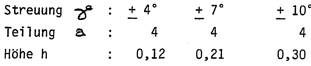
Figur 5: ein Anwendungsbeispiel einer brechenden Struktur mit Angabe der Maßverhältnisse;Figure 5: an application example of a refractive structure with details of the proportions;
Figur 6: eine Stirnansicht einer Leuchtenabdeckung nach der Neuerung;Figure 6: an end view of a lamp cover after the innovation;
Figur 7: ein größerer Teilschnitt durch die Leuchtenabdeckung nach Figur 6.Figure 7: a larger partial section through the lamp cover according to Figure 6.
Gemäss Figur 1 fällt ein Strahlenbündel 1 auf eine durchscheinende Struktur, wobei im Polardiagramm der Intensität dieses auf eine Struktur einfallende Strahlenbündel relativ schmal ausgebildet ist, d.h. bezogen
auf die Intensität stark gerichtet ist.According to FIG. 1, a bundle of rays 1 falls on a translucent structure, the beam of rays incident on a structure in the polar diagram of the intensity being relatively narrow, that is to say related is strongly focused on the intensity.
Die Figur 2 zeigt den Erfolg der vorliegenden Neuerung, nämlich , daß ein die Struktur verlassendes Strahlenbündel 2 stark gerichtet ist, jedoch eine gewisse Strahlaufweitung aufweist, wobei der Winkel Gamma die Hälfte der gewünschten Strahlaufweitung darstellt.FIG. 2 shows the success of the present innovation, namely that a beam 2 leaving the structure is strongly directed, but has a certain beam expansion, the angle gamma representing half of the desired beam expansion.
Wichtig ist, daß auch das Strahlenbündel 2, welches die Struktur verlässt, relativ stark gerichtet ist und im wesentlichen keinen Streuanteil enthält. Im übrigen ist wesentlich, daß es in die gleiche Richtung gerichtet ist, wie das einfallende Strahlenbündel 1, woraus sich ergibt, daß die neuerungsgemässe Leuchtenabdeckung ein gerichtetes Licht abgibt, dies im Gegensatz zu opalen Abdeckungen, die nur streuen. Im übrigen besteht auch ein Unterschied zu den vorher erwähnten Prismen-Strukturen, weil derartige Prismen-Strukturen keine Strahlenaufweitung durchführen, sondern nur eine Strahlu !enkung, d.h. das einfallende Strahlenbündel wird in einer anderen Richtung abgestrahlt. Dies ist nicht Zweck der vorliegenden Neuerung.It is important that the radiation beam 2, which leaves the structure, is directed relatively strongly and contains essentially no scatter component. Moreover, it is essential that it is directed in the same direction as the incident beam 1, which means that the luminaire cover according to the invention emits a directed light, in contrast to opal covers that only scatter. For the rest, there is also a difference to the prism structures mentioned above, because such prism structures do not expand the beam, but only deflect it, i.e. the incident beam is emitted in a different direction. This is not the purpose of the present innovation.
Durch die beschriebene Strahlaufweitung wird also der vorher erwähnte Weichzeichner-Effekt erreicht, so daß von vornherein störende Schlieren und Schattenabbildungen auf bestrahlten Wänden vermieden werden.The previously described soft focus effect is achieved by the described beam expansion, so that from the outset annoying streaks and shadows are avoided on irradiated walls.
Unter Bezugnahme auf die späteren Zeichnungen werden folgende Parameter
With reference to the later drawings, the following parameters
definiertAre defined
= Hälfte der Strahlenaufweitung= Half of the beam expansion
α. = Maximale Abweichung von der parallelen Platte sind <*= xα. = Maximum deviation from the parallel plate is <* = x
5i »/Sr= Brechungswinkel5 i »/ S r = angle of refraction
h = halbe Tiefe der Strukturh = half the depth of the structure
<& = halbe Breite der Struktur<& = half the width of the structure
Die Figur 3 zeigt in allgemeiner Form das Brechungsgesetz, wenn ein bestimmtes Strahlenbündel im Winkel Alpha auf eine brechende Oberfläche auftrifft und diese im Winkel Beta verlässt.FIG. 3 shows the refraction law in general form when a specific beam hits the refractive surface at an angle alpha and leaves it at an angle beta.
n ist hierbei der Brechungsindex.n is the refractive index.
Hierbei gilt die FormelThe formula applies here
sin Ä n = sin ßsin Ä n = sin β
In Figur 4 ist eine wellenförmige Struktur 3 dargestellt, wobei mit dieser Struktur die Oberfläche der Leuchtenabdeckung ausgebildet sein soll .A wavy structure 3 is shown in FIG. 4, the structure of the surface of the lamp cover being designed with this structure.
Mit dem Parameter a ist die halbe Breite der Struktur definiert, während mit dem Parameter h die halbe Tiefe der Struktur definiert wird.The parameter a defines half the width of the structure, while the parameter h defines half the depth of the structure.
Wenn nun ein strahlabgebendes Lichtbündel 1 von unten auf die wellenförmige Struktur 3 auftrifft, dann verlässt dieses Lichtbündel 2 die Struktur 3 in der in Figur 4 dargestellten Form, wobei der Winkel Gamma die Hälfte der Strahlaufweitung darstellt. D.h. das parallel
unterhalb der Struktur einfallende Strahlenbündel 1 wird nach Durchtreten durch die Struktur 3 an jeder Seite um den Winkel Gamma aufgeweitet.If a beam of light 1 emitting rays strikes the undulating structure 3 from below, then this light beam 2 leaves the structure 3 in the form shown in FIG. 4, the angle gamma representing half of the beam expansion. Ie that in parallel Beams 1 incident below the structure are expanded by the angle gamma on each side after passing through the structure 3.
Man erkennt, daß der Winkel Alpha der Winkel ist, der maximal zulässig ist, der damit die maximal zulässige Abweichung der wellenförmigen Struktur 3 von einer parallelen Platte 4 beschreibt.It can be seen that the angle alpha is the maximum permissible angle, which thus describes the maximum permissible deviation of the wavy structure 3 from a parallel plate 4.
D.h. der Winkel Alpha ist auch als maximal zulässiger Tangentenwinkel an die wellenförmige Struktur 3 aufzufassen.That the angle alpha is also to be understood as the maximum permissible tangent angle to the wavy structure 3.
Der Winkel Alpha folgt hierbei der nachstehend wiedergegebenen FormelThe angle alpha follows the formula shown below
4h a4h a
= sin <x.= sin <x.
4h8 1+ a2 4h 8 1+ a 2
Diese Formel beschreibt eine Dimensionsangabe für die wellenförmige Struktur, wobei in Figur 5 einige Werte ausgerechnet sind bezogen auf unterschiedliche Strukturen der wellenförmigen Struktur 3.This formula describes a dimension specification for the wavy structure, with some values in FIG. 5 being calculated in relation to different structures of the wavy structure 3.
Einige Auswertungen dieser Formel ergeben Ergebnisse, wie nachstehend angegeben:Some evaluations of this formula give results as shown below:
Nachfolgend wird auch noch der Zusammenhang zwischen dem Winkel Alpha, dem Winkel Gamma und dem Brechungsindex angegeben.
-8-The relationship between the angle alpha, the angle gamma and the refractive index is also given below. -8th-
= arcsiin In sin Ick- arc sin ( ti
= arcsiin In sin Ick- arc sin (ti
Jm ausgeführten Beispiel gemäss Figur 5 und den obenstehenden Werten wird hierbei von einer Leuchtenabdeckung aus dem Material Wacrolon ausgegangen mit einem Brechungsindex von n = 1,586. In the example according to FIG. 5 and the above values, a luminaire cover made of Wacrolon material is assumed with a refractive index of n = 1.586.
In den Figuren 6 und 7 ist ein ausgeführtes Beispiel für eine derartige Leuchtenabdeckung 5 angegeben.FIGS. 6 and 7 show an example of such a lamp cover 5.
Hierbei wäre eine Lampe bei Position 6 angeordnet, wobei aus Reinhaltungsgründen die von der Lampe abgewandte Oberseite der Leuchtenabdeckung 5 (Oberseite 7) glatt ausgebildet ist. Die Unterseite (die zur Lampe zugewandte Seite 8) trägt die vorher beschriebene, wellenförmige Struktur 3.A lamp would be arranged at position 6, the upper side of the lamp cover 5 (upper side 7) facing away from the lamp being made smooth for reasons of cleanliness. The underside (the side 8 facing the lamp) bears the wavy structure 3 described above.
Hierbei wird es von der vorliegenden Neuerung umfasst, dass sowohl die Oberseite 7 als auch die Unterseite 8 eine derartige wellenförmige Struktur tragen.It is encompassed by the present innovation that both the top 7 and the bottom 8 carry such a wavy structure.
Es versteht sich vonseibst, daß die Leuchtenabdeckung 5 den verschiedensten, ansich bekannten, Leuchtenzwecken dienen kann, nämlich zur Abdeckung der Leuchte bei Position 6 nach oben und ebenso zur Abdeckung der Leuchte nach unten oder auf eine zu bestrahlende Seite.It goes without saying that the lamp cover 5 can serve a wide variety of known lighting purposes, namely to cover the lamp at position 6 upwards and also to cover the lamp downwards or on a side to be irradiated.
Ebenso kann es vorgesehen sein, daß die neuerungsgemässe Leuchtenabdeckung die Leuchte von allen Seiten umgibt. Aus Figur 7 sind weitere Einzelheiten der wellenförmigen Struktur 3 zu entnehmen.It can also be provided that the luminaire cover according to the innovation surrounds the luminaire from all sides. 7 shows further details of the wave-shaped structure 3.
Hier wurde die Sinusfunktion, die vorher errechnet wurde, durch entsprechende Radienkurven angenähert. Von einer Bezugslinie 9 ausgehend sind hierbei Radiusstrecken mit einem Radius von jeweils 3,6mm (ausgehend von der Bezugslinie 9) hintereinanderfolgend in stetiger Aneinanderreihung aneinandergefügt.
Hierbei ist wichtig, daß die in Figur 7 gezeigten "Wellenberge" die Radienstücke betreffen, die von der unteren Bezugslinie 9 ausgehen, während die in Figur 7 dargestellten "Wellentäler" von einer oberen Bezugslinie 9 ausgehen.Here the sine function, which was calculated beforehand, was approximated by corresponding radius curves. Starting from a reference line 9, radius sections each having a radius of 3.6 mm (starting from the reference line 9) are successively joined together in a row. It is important here that the "wave crests" shown in FIG. 7 relate to the radii that start from the lower reference line 9, while the "wave troughs" shown in FIG. 7 start from an upper reference line 9.
Die Bezugslinien 9 sind hierbei zu einer gemittelten Oberfläche 10 symmetrisch.The reference lines 9 are here symmetrical to an averaged surface 10.
Die Materialstärke 11 von z.B. 2,4 mm ist in weiten Grenzen variierbar und hängt von den Materialeigenschaften des verwendeten Materials ab.The material thickness 11 of e.g. 2.4 mm can be varied within a wide range and depends on the material properties of the material used.
Die Punkte 12 und 13 beschreiben den Abstand zwischen zwei Wellenbergen, wobei Geraden 14,15 durch diese Punkte 12,13 hindurchgehen und sich in gegenüberliegenden Punkten 16,17 der gegenüberliegenden Bezugslinie schneiden.Points 12 and 13 describe the distance between two wave crests, with straight lines 14, 15 passing through these points 12, 13 and intersecting at opposite points 16, 17 of the opposite reference line.
Der Winkel 18 zwischen den Geraden 14,15 beträgt dann beispielsweise 33, 42°.The angle 18 between the straight lines 14, 15 is then, for example, 33, 42 °.
Weil die gesamte Abdeckung noch gemäss Figur 6 sphärisch gebogen ist, ergibt sich ein oberer Winkel 19 mit einem Wert von z.B. 32,91°.Because the entire cover is still spherically curved according to FIG. 6, there is an upper angle 19 with a value of e.g. 32.91 °.
Bei der vorliegenden Erfindung handelt es sich also um die Verwendung einer "gezielten" Rillenstruktur in einer Leuchtenabdeckung, die im vorliegenden Ausführungsbeispiel nur für die Verwendung mit einer Leuchtstofflampe beschrieben wurde. In den Rahmen der vorliegenden Neuerung fallen jedoch die Anwendungen mit anderen Beleuchtungslampen, wie z.B. Halogenlampen oder Glühlampen.The present invention therefore relates to the use of a “targeted” groove structure in a luminaire cover, which was described in the present exemplary embodiment only for use with a fluorescent lamp. Within the scope of the present innovation, however, the applications with other lighting lamps, such as Halogen lamps or incandescent lamps.
Bei der Verwendung derartiger Beleuchtungskörper würden die Rillenstrukturen dann nicht parallel zur Längsachse der vorher beschriebenen Leuchtstofflampe verlaufen, sondern die Rillenstrukturen wären konzentrische Rillenstrukturen oder auch lokalkonzentrische
Rillenstrukturen, wobei man derartige ringförmige Strukturen über die Oberfläche einer Leuchtenabdeckung verteilt.If lighting fixtures of this type were used, the groove structures would then not run parallel to the longitudinal axis of the fluorescent lamp described above, but the groove structures would be concentric groove structures or also locally concentric Groove structures, such ring structures being distributed over the surface of a lamp cover.
Es wurde vorstehend noch darauf hingewiesen, daß bevorzugte Dimensionen für die wellenförmige Struktur vorhanden sind, wobei die obere Grenze nur von den material echnischen Eigenschaften des Materials und von dem verwendeten Werkzeug zur Anbringung der wellenförmigen Strukturen abhängt. Dies bedeutet, daß man statt einer z.B. aus Macrolon bestehenden Leuchtenabdeckung auch eine dünne Folie verwenden kann, wobei die vorher beschriebenen wellenförmigen Strukturen im Mikrometerbereich in diese Struktur eingeformt sind.
It was pointed out above that there are preferred dimensions for the wavy structure, the upper limit depending only on the material's technical properties and on the tool used to apply the wavy structures. This means that instead of a lamp cover made of Macrolon, for example, a thin film can also be used, the wavy structures described above being molded into this structure in the micrometer range.
λ .λ.
ZEICHNUNGS-LEGENDEDRAWING LEGEND
Strahlenbündel " wellenförmige Struktur parallele Platte Leuchtenabdeckung Position Oberseite Unterseite Bezugslinie Oberfläche Materialstärke Punkt Punkt Gerade Gerade Punkt " Winkel Winkel
Beam "wavy structure parallel plate lamp cover position top underside reference line surface material thickness point point straight line point" angle angle