WO1981002631A1 - Leakage detection method using helium - Google Patents
Leakage detection method using helium Download PDFInfo
- Publication number
- WO1981002631A1 WO1981002631A1 PCT/JP1981/000048 JP8100048W WO8102631A1 WO 1981002631 A1 WO1981002631 A1 WO 1981002631A1 JP 8100048 W JP8100048 W JP 8100048W WO 8102631 A1 WO8102631 A1 WO 8102631A1
- Authority
- WO
- WIPO (PCT)
- Prior art keywords
- helium
- gas
- detector
- leak
- membrane
- Prior art date
Links
Classifications
-
- G—PHYSICS
- G01—MEASURING; TESTING
- G01M—TESTING STATIC OR DYNAMIC BALANCE OF MACHINES OR STRUCTURES; TESTING OF STRUCTURES OR APPARATUS, NOT OTHERWISE PROVIDED FOR
- G01M3/00—Investigating fluid-tightness of structures
- G01M3/02—Investigating fluid-tightness of structures by using fluid or vacuum
- G01M3/04—Investigating fluid-tightness of structures by using fluid or vacuum by detecting the presence of fluid at the leakage point
- G01M3/20—Investigating fluid-tightness of structures by using fluid or vacuum by detecting the presence of fluid at the leakage point using special tracer materials, e.g. dye, fluorescent material, radioactive material
- G01M3/202—Investigating fluid-tightness of structures by using fluid or vacuum by detecting the presence of fluid at the leakage point using special tracer materials, e.g. dye, fluorescent material, radioactive material using mass spectrometer detection systems
-
- G—PHYSICS
- G01—MEASURING; TESTING
- G01M—TESTING STATIC OR DYNAMIC BALANCE OF MACHINES OR STRUCTURES; TESTING OF STRUCTURES OR APPARATUS, NOT OTHERWISE PROVIDED FOR
- G01M3/00—Investigating fluid-tightness of structures
- G01M3/02—Investigating fluid-tightness of structures by using fluid or vacuum
- G01M3/04—Investigating fluid-tightness of structures by using fluid or vacuum by detecting the presence of fluid at the leakage point
- G01M3/20—Investigating fluid-tightness of structures by using fluid or vacuum by detecting the presence of fluid at the leakage point using special tracer materials, e.g. dye, fluorescent material, radioactive material
- G01M3/22—Investigating fluid-tightness of structures by using fluid or vacuum by detecting the presence of fluid at the leakage point using special tracer materials, e.g. dye, fluorescent material, radioactive material for pipes, cables or tubes; for pipe joints or seals; for valves; for welds; for containers, e.g. radiators
- G01M3/226—Investigating fluid-tightness of structures by using fluid or vacuum by detecting the presence of fluid at the leakage point using special tracer materials, e.g. dye, fluorescent material, radioactive material for pipes, cables or tubes; for pipe joints or seals; for valves; for welds; for containers, e.g. radiators for containers, e.g. radiators
Definitions
- the present invention relates to a method of detecting a system leak using a leak detector, and in particular, a partial pressure ratio of helium reaching a detector tube (mass spectrometer tube) using a membrane that can selectively transmit a Helium gas. This increases the leak detection sensitivity while preventing contamination or breakage of the detector tube.
- the air will be displaced by the air and flow into the system through the place, and the partial pressure of the remaining gas in the gas (the gas in the system) will increase and eventually the place
- the partial pressure of Helium in the detector tube increases, and the increase is detected.
- the system was diluted to helm or appropriate concentration.
- the room is pressurized and sealed, and the leak of the gas from the leak location to the outside is sucked by a steam leak detector and introduced into the detection tube.
- the introduced gas is replaced by air components due to leakage, and is rich in helium components and is detected.
- the conventional laser leak detector is basically composed of a test boat 1, a throttle valve 2, a diffusion bomb 3, an exhaust pipe 4, a mass spectrometer pipe 5, and a rotary bomb (not shown) as shown in Fig./Fig. It is structured.
- Gas containing air from the system (or sniffer nozzle) from the system flows into the test boat 1 and flows through the throttle valve 2 as needed. After being decompressed, it is sucked by the diffusion bomb 3 and exhausted from the exhaust pipe 4.
- the mass spectrometer pipe 5 is provided in the space inside the diffusion bomb 3 on the throttle valve 2 side, and the space of the The pressure is measured.
- the throttle valve 2 is configured so that the air partial pressure (pressure obtained by subtracting the Helium component from the total pressure) in the sample gas introduced into the test port 1 is in the space of the mass spectrometer tube 5, and the diaphragm of the spectrometer is used. at a minimum to prevent burning of the bets are placed in order to keep under / over 4 T orr.
- the valve function variably reduces or attenuates the total pressure itself due to its one characteristic, and the partial pressure ratio (component ratio) between air and air becomes constant before and after the valve, and there is no selective restriction. There is no ability. That is, the partial pressure of air applied to test boat 1
- the total pressure in the mass spectrometer tube 5 is P 2
- the partial pressure of the helium is P 2 s
- the conductance of the throttle valve 2 is Cv
- the effective pumping speed of the diffusion bomb 3 is Sv
- the space of the mass spectrometer tube 5 is Assuming that V is the volume of the space between the valve 2 and the high pressure of the diffusion bomb 3, the helium partial pressure B in the mass analysis curve 5 is given by the following equation (1). Is represented.
- time helicopter ⁇ beam partial pressure P 2 H in the mass spectrometer tube 5 Given the magnitude of the P 2 s except dependent term is [rho 2 ⁇ orr next, when fixed to a certain value data, mass spectrometry In order to increase the determined 0 P 2 B depending on the total pressure of the pipe 5, it is necessary to increase the value of, but that will necessarily increase the partial pressure of the air * air component. As described above, it is not desirable that the partial pressure of the air component exceed / ⁇ * Torr in order to prevent the analysis tube filament from burning. Thus:: P 2 H stays at the maximum of / 4 To rr. In the case where the result cannot be increased, for example, when the gas load due to degassing of the system is large and the leakage is small, there is a disadvantage that it is difficult to detect the leakage.
- the mass spectrometer tube 5 is connected to the system only by the throttle valve 2, the mass spectrometer tube 5 is easily contaminated by dust, fumes, etc. in the system, and is likely to cause deterioration of the signal. There was a disadvantage.
- the present invention seeks to expand the range of system leak detection that can be performed by a room leak detector by using a membrane that selectively transmits a vehicle, and the presence of the film makes the leak detection unnecessary. Air components, dust, and fumes are suppressed, and leak detectors are detected.
- the size of the system was reduced, and the leak detector itself was reduced in size, and at the same time, contamination of the mass spectrometer tube was prevented, thereby improving the reliability of the leak detector.
- the purpose is to provide a method for detecting leaks.
- the method of the present invention uses a membrane (referred to as a “permeate membrane”), for example, a polystyrene membrane, which can selectively transmit permeate gas relative to air in a hemi leak detection. Essence.
- a membrane for example, a polystyrene membrane, which can selectively transmit permeate gas relative to air in a hemi leak detection. Essence.
- the Helium gas that enters the system after being replaced with the air component at the location of the leak is mixed with the existing gas and permeates through the Helium permeable membrane as a sample gas, which makes it undetectable by this membrane.
- air mainly N 2 or O
- the ratio of the hemispheric components in the analysis tube space is increased in proportion to the t of the product of the partial pressure difference and the permeability in comparison with the hemisphere component ratio of the sample gas.
- the partial pressure of the helium in the gas having the increased helium component is measured by a mass spectrometer.
- the magnitude of the change in the partial pressure of the helium in the analysis tube depends on the magnitude of the replacement of the air component gas with the helium gas at the leaking unit, and the presence or absence of the helium component is increased by the action of the membrane. After this, the magnitude of the leak is detected.
- the sucked sample gas is placed at an appropriate position reaching the analysis tube, for example, at a probe tip.
- the leak is detected by the method of the present invention.
- WIPO Figure 2 is a schematic diagram showing a conventional hemi leak detector
- Figure 2 is a schematic diagram showing the basic configuration of the hemi leak detector used in the present invention
- Figure J is a system using a raw exhaust chamber.
- Connection diagram when a system leak is detected by a hemi-leak detector while heating shows a connection diagram when the back pressure method is applied
- FIG. 2 shows a basic configuration of the present invention, in which a permeable membrane 6 is provided instead of the throttle valve 2 shown in FIG.
- the hemisphere in the sample gas mainly a mixed gas consisting of air, a small amount of helicopter, and air
- the permeable membrane 6 passes through the diffusion pump 3, and is exhausted. It is sensed by the analysis tube 5.
- the permeable membrane 6 is kept at a partial pressure of air / 0- * Torr or less in the mass spectrometer tube 5 similarly to the throttle valve 2 shown in FIG. Further, the permeable membrane 6 plays a role of increasing the helium concentration in the mass spectrometer tube 5 by selectively transmitting the helium.
- the air partial pressure A applied to the test boat 1 is assumed to be constant, as in the case of FIG.
- the conductance to the air is the conductance CA to the air
- the effective pumping speed of the diffusion bomb 8 is Sn
- the volume of the space on the permeable membrane 6 side of the diffusion bomb 3 is V , the total pressure in the mass fraction ⁇ 5 / - 4
- equation ( 2 ) becomes equation ( 3 ) below.
- the present invention is based on the above-described findings, and has the advantage that a system leak can be detected by a relatively high change in helium partial pressure, and a device for detecting system leak can be downsized. Further, since the permeable membrane 6 also plays a role of a filter, an advantage that the mass spectrometer tube 5 can be prevented from being infected by dust fume or the like can be obtained.
- FIGS. J to J show representative embodiments of the present invention.
- system A is, for example, a tank or piping used for vacuum or high pressure.
- the heavy leak detector B includes a test boat 1, a diffusion bomb 8, a mass spectrometer tube 5, a permeable membrane 6, throttle valves 7, 8, 9 and rotary bombs 10, 11.
- a helium leak detector and a main exhaust pump 21 are connected to the system A via pipes 22 and 23, respectively.
- the main exhaust boat of System A and the inspection boat_ May be shared.
- the main exhaust pump 21 is a vacuum bomb such as a gas bomb, and evacuates the system A to a predetermined low vacuum pressure.
- the sample gas flowing into the test boat 1 is guided to the mass spectrometer tube 5 through the permeable membrane 6.
- the helical gas partial pressure ratio of the sample gas after passing through the permeable membrane 6 is higher than the helical gas partial pressure ratio of the sample gas before passing through the permeable film 6 by the permeable membrane 6, and the The steam partial pressure ratio is sensed up to the mass spectrometer tube 5, and then exhausted by the diffusion horn 8 and the rotary pump 10 via the throttle valve 8.
- the degree of vacuum in the mass spectrometer tube 5 is adjusted by the throttle valves 7 and 8.
- the rotary bomb 11 is for replacing the sample gas flowing into the permeable membrane 6, and the throttle valve 9 is provided for adjusting the effective pumping speed of the same.
- the rotary bomb 11 may be shared with the rotary bomb 10. In this case, fifteen pipes after the throttle valve 9 are connected to the pipe 4 connecting the diffusion bomb 3 and the ⁇ -tali pump 10. Further, the rotary horn 11 is provided with another true depending on the pressure of the sample gas flowing into the permeable membrane 6. It is also possible to substitute an empty pump or a suction bomb.
- the embodiment of FIG. 3 is effective as a detection method when the system has a large leak, that is, when a high vacuum cannot be maintained in the system.
- the pressure in the system / - 1 Tor r, a helicopter ⁇ beam concentration is / ⁇ click ppm of which, the pressure in the mass spectrometer tube is / - when was s Torr, in the conventional method by weight
- the partial pressure of the air in the analytical tube was / ⁇ -1 >> Tor r.
- the leak leak detector shown in 3 ⁇ the conductance of the vehicle is / X / 0 ⁇ M, '; the transmissive film has an empty conductance of X / 0.1e / s. O, the partial pressure of the helium was doubled after / second and twice as high as that of the solitary method.
- the sample gas in the system A is exhausted by the diffusion bomb 31 and the rotary bomb 32, and the pipe 8'8 is connected to the back pressure side of the diffusion bomb 31 through the pipe 8'8.
- the helicopter and detector B shown in the figure are connected in series to detect system leaks, and the same ghost as in the embodiment shown in Fig. 3 can be obtained.
- a pressurized room is sealed in a system, and leakage of the system can be detected.
- a helium or a mixed gas containing a helium as a main component is pressurized and filled to a pressure higher than the atmospheric pressure in system A (the slant indicates a pressurized state).
- a test hose 1 of leak detector B is connected to a vacuum hose 41, and a sniffer nozzle 42 connected to the other end of the vacuum hose 41 detects a leaked vehicle outside system A.
- This method is an application of the usual sniffer method. Ever since, this method was used by Sfurnos
- CMPI Since the pressure difference between the atmospheric pressure and the high vacuum pressure of the hem leak detector must be maintained, the tip has a structure with fine holes, so there was an inconvenience that dust and the like became clogged. .
- the tip of the sniffer nozzle can be constituted by a relatively large hole, it is possible to eliminate the inconvenience of clogging such as dust and to improve the detection capability remarkably. it can.
- the mass spectrometer maintains a high vacuum pressure of / Torr
- the realm conductance is / X / 0 ⁇ * JL
- the air conductance is processing was carried out as shown in FIG using transmission ⁇ of's "2 X / over 8 Zs, about fold from Yodo come re ⁇ beam partial pressure to the quality 'weight analysis tube / transfer JK response time under could be enhanced.
- a detector having a permeable membrane for selectively transmitting a vehicle may be used instead of the spheroid nozzle.
- This detector has, for example, a cutout in the shape of a drawn wall at the tip of a tube, and a permeation membrane provided inside the tube.
- the embodiment of FIG. 3 is a method suitable for a case where the system can maintain a relatively high vacuum pressure state.
- the exhaust in the stem A is performed only by the leak detector C via the pipe 51, or a separate exhaust pipe consisting of the diffusion bomb 53 and the rotary bomb 54 connected by the pipe 52 is used. This is a method of detecting leakage while operating the exhaust device.
- the sample gas flowing into the leak detector C from the test boat 1 is sucked into the diffusion bomb 3 through the throttle valve 55 and then exhausted by the w-bomb 10.
- a part of the sample gas between the wiping pump 3 and the rotary pump 10 permeates the permeable membrane 6 to increase the partial pressure ratio of the helium gas.
- This gas is sucked into the diffusion bomb 3 again through the throttle valve 57.
- the throttle valve 57 is used to adjust the effective pumping speed of the diffusion chamber 8 for the poor analysis tube.o
- the sample gas is transmitted through a permeable membrane that can selectively transmit the air in comparison with air, and the partial pressure ratio of the gas is increased. Is detected by a mass spectrometer tube.
- the permeable membrane used has a relatively large separation coefficient (helium tightness + air permeability) for the helium and air, and has a low conductance at least for the helical permeability. Convert to / - 4 A / s j3 ⁇ 4 wear shall be desirable. It is also desirable to be able to process thin films easily, but a polymer film such as polystyrene was effective as a means to meet such requirements.
- the permeable membrane increases the partial pressure ratio of the helium gas in the sam- ble gas and can be detected by the mass spectrometer tube, the detection sensitivity is remarkably improved and the detection accuracy is also improved. Due to the filter effect of the permeable membrane, the inside of the mass spectrometer tube can always be kept clean, and the reliability is improved. In addition, since it is not necessary to use a throttle valve or a water nozzle having a raden capillary, the inconvenience caused by clogging due to dust can be completely eliminated.
- the exhaust speed is / ⁇ ⁇ 2 s diffusion bomb and the back pressure of the diffusion bomb is exhausted. It is necessary to have a rotary bomb with a pumping speed of ⁇ 2 ⁇ ⁇ (ID
- a vacuum trapping system such as a tank and a storage tube. It may also be used for inspection of other airtight systems such as high pressure tanks, high pressure storage tubes, etc.
Abstract
A method for detecting leakage in a vacuum or high-pressure apparatus, piping, or the like using a helium detector (5), which comprises increasing the relative partial pressure of helium reaching a helium detector (5) by means of membrane (6), allowing helium gas to selectively permeate therethrough, and detecting the resulting helium. A sample of gas from a system which is to be detected for leakage, or a sniffer probe, is introduced into test port (1), helium in the gas permeates through the helium-permeating membrane (6) and is detected by helium detector (5) in the course of being discharged via pump (3). The helium-permeating membrane (6) maintains partial pressure of air in the helium detector at a level of 10-4 Torr or less, and also functions as a filter.
Description
明 細 書 へリゥムを用いてシステムの漏洩を検知する方法 技 術 分 野 Description How to detect system leaks using a realm
本発萌はヘリ ゥムリ ークディテクタを用いてシステムの漏洩を検 知する方法に関し、 特にヘリ ゥムガスを選択的に透過し得る膜を用 いて検知管 (質量分析管) に到達するヘ リ ウムの分圧比を增大させ これにより検知管の汚染あるいは、 破損を防止しながら漏洩検知感 度の増大をはかったものである。 The present invention relates to a method of detecting a system leak using a leak detector, and in particular, a partial pressure ratio of helium reaching a detector tube (mass spectrometer tube) using a membrane that can selectively transmit a Helium gas. This increases the leak detection sensitivity while preventing contamination or breakage of the detector tube.
背 景 技 術 - . Background technology-.
—殺に真空又は高 を取り扱う装置あるいは配管等の漏洩個所及 び漏洩量検知にはヘリ ゥム リ ークディテクタが多用されている。 へ リ ウムリークディテクタを用いたリークディテクシヨンは、 ヘリ ゥ ムが空気中にわずかしか含まれておらず、 人為的にヘリ ゥムを導入 しなけれぱ、 空気中のへリ ゥムがほほ一定成分比しか存在しないこ とを積極的に利用するものである。 また、 この検知方法は具体的に 大別して、 真空法と加 法の ·2種類の方法がある o 真空法に於ては 被試験体 (システム) 内をヘリ ウム リ ークディ テク タ の排気系単独 あるいは他の補助排気系と共同して真空排気しながら、 铵検査假所 に外便からヘリ ゥムを吹きつける。 渥浅髌所か'存在すると、 その倔 所を通してヘリ ゥムが空気と置換してシステム内に流入し、 残存ガ ス (システム内のガス) 中のヘリ ゥム分圧が増大し結局の所検知管 部でのヘ リ ゥム分圧の増大をもたらしその増加分が検知される。 加 圧法に於ては、 システムにヘリ ゥム又は適当な濃度に薄められた.へ —Small leak detectors are frequently used to detect leaks and the amount of leaks in devices or pipes that handle vacuum or high pressure. In the leak detection using the Helium leak detector, the helicopter is only slightly contained in the air, and the helicopter in the air is almost constant unless the helicopter is introduced artificially. The fact that only the component ratio exists is actively used. In addition, this detection method is roughly classified into two types, a vacuum method and an additive method. O In the vacuum method, the exhaust system of the helium leak detector is used only inside the test object (system). Or, while evacuating in cooperation with other auxiliary exhaust systems, spray a helmet from outside service to the inspection area. If there is an atsasa place, the air will be displaced by the air and flow into the system through the place, and the partial pressure of the remaining gas in the gas (the gas in the system) will increase and eventually the place The partial pressure of Helium in the detector tube increases, and the increase is detected. In the pressurized method, the system was diluted to helm or appropriate concentration.
OMPI OMPI
/.' \v ir'O
リ ゥムを加圧封入し、 該ガスが漏洩個所から外側に漏洩するのを、 ヘリ ゥムリークディテク タによって吸引し、 検知管部に導入する。 導入されてきたガス 分は漏洩によって空気成分と置換された分だ けヘリ ゥム成分に富み、 検知される。 /. '\ v ir'O The room is pressurized and sealed, and the leak of the gas from the leak location to the outside is sucked by a steam leak detector and introduced into the detection tube. The introduced gas is replaced by air components due to leakage, and is rich in helium components and is detected.
従来のヘリ ゥム リ ークディテク タは第 / 図に示すよ う にテス ト ホート 1、 絞り弁 2、 拡散ボンブ 3、 排気管 4、 質量分析管 5および ロータ リ ボンブ (図示略) によ り基本的に構成されている。 The conventional laser leak detector is basically composed of a test boat 1, a throttle valve 2, a diffusion bomb 3, an exhaust pipe 4, a mass spectrometer pipe 5, and a rotary bomb (not shown) as shown in Fig./Fig. It is structured.
システムからあ-るいはス - フアブ π—ブ (スニ ファノ ズル) から のヘ リ ゥムを含むガス (以下サンブルガスと呼称する) は、 テス ト ボート 1に流入し絞り弁 2によって必要に応じて減圧された後、 拡 散ボンブ 3によって吸引されて排気管 4から排気される ¾ 質量分析 管 5は絞り弁 2側の拡散ボンブ 3内の空間に設けられ、 この空間の ヘリ ゥムの分圧が測定される。 Gas containing air from the system (or sniffer nozzle) from the system (hereafter referred to as “sumble gas”) flows into the test boat 1 and flows through the throttle valve 2 as needed. After being decompressed, it is sucked by the diffusion bomb 3 and exhausted from the exhaust pipe 4.The mass spectrometer pipe 5 is provided in the space inside the diffusion bomb 3 on the throttle valve 2 side, and the space of the The pressure is measured.
絞り弁 2はテス トポ一 ト 1に導入されるサンブルガス中の空気分 圧 (全圧からヘ リ ゥム分压を差引いた圧力) が質量分析管 5の空間 内で該分析管のフイラメ ン トの焼損を防止する に少く とも / ー4 T o r r以下に維持させる為に設置されている。 弁機能は一铰の性 質からして、 全圧そのものを可変減;衰させるものであり、 空気とへ リ ゥムの分圧比 (成分比) は弁前後で一定となり、 何らの選択的絞 り檨能はない。 すなわち、 テス トボート 1に印加される空気分圧The throttle valve 2 is configured so that the air partial pressure (pressure obtained by subtracting the Helium component from the total pressure) in the sample gas introduced into the test port 1 is in the space of the mass spectrometer tube 5, and the diaphragm of the spectrometer is used. at a minimum to prevent burning of the bets are placed in order to keep under / over 4 T orr. The valve function variably reduces or attenuates the total pressure itself due to its one characteristic, and the partial pressure ratio (component ratio) between air and air becomes constant before and after the valve, and there is no selective restriction. There is no ability. That is, the partial pressure of air applied to test boat 1
Ρμ を一定とし、 ヘリ ゥム分圧: P!Hを下記のように仮定する c Assuming that Ρμ is constant and the partial pressure of the helium: P! H is as follows c
tt

また質量分析管 5内の全圧を P2 、 ヘリ ゥム分圧 P2s、 絞り弁 2 のコ ンダク タ ンスを Cv、拡散ボンブ 3の実効排気速度を Sv、質量分 析管 5の空間を含む、 紋り弁 2と挞散ボンブ 3の高真空倒との間の 空間の体積を Vとすると、 質量分析彎 5内のヘ リ ウ ム分圧 Bは下 記の (1)式によって表わされる。
 The total pressure in the mass spectrometer tube 5 is P 2 , the partial pressure of the helium is P 2 s, the conductance of the throttle valve 2 is Cv, the effective pumping speed of the diffusion bomb 3 is Sv, and the space of the mass spectrometer tube 5 is Assuming that V is the volume of the space between the valve 2 and the high pressure of the diffusion bomb 3, the helium partial pressure B in the mass analysis curve 5 is given by the following equation (1). Is represented.
従って、 時間に依存する項を除いて P2sの大きさを考えると質量 分析管 5中のヘリ ゥム分圧 P2Hは Ρ2· orrとなり、 タをある値に 固定すると、 質量分析管 5の全圧に佐存し、 決定される 0 P2B を大 にするには を大にすれば良いが、 それは必然的に空 *気成分の分 圧を高めることになる o しかし前述したように、 分析管フイ ラメ ン トの焼損防止の為に空気成分の分圧を / ^ * Torr を越えることは 望ましくない。 従って、 : P2Hは最大僮/ -4 To r r にとどまる。 その結果 を大にすることができないケース、 例えばシステムの脱 ガス等によるガス負荷が大であって、 漏洩が小さい時などに ¾ては、 漏洩検知が困難にな という欠点があった。 Therefore, time helicopter © beam partial pressure P 2 H in the mass spectrometer tube 5 Given the magnitude of the P 2 s except dependent term is [rho 2 · orr next, when fixed to a certain value data, mass spectrometry In order to increase the determined 0 P 2 B depending on the total pressure of the pipe 5, it is necessary to increase the value of, but that will necessarily increase the partial pressure of the air * air component. As described above, it is not desirable that the partial pressure of the air component exceed / ^ * Torr in order to prevent the analysis tube filament from burning. Thus:: P 2 H stays at the maximum of / 4 To rr. In the case where the result cannot be increased, for example, when the gas load due to degassing of the system is large and the leakage is small, there is a disadvantage that it is difficult to detect the leakage.
また、 質量分析管 5は絞り弁 2のみによってシステムに接続され ているため、 システム内のダス ト、 ヒューム等によって汚染されや すく、 信賴拴の悪化をもたらしやすいし、 さらには絞り弁 2の閉塞 という欠点があった。 Further, since the mass spectrometer tube 5 is connected to the system only by the throttle valve 2, the mass spectrometer tube 5 is easily contaminated by dust, fumes, etc. in the system, and is likely to cause deterioration of the signal. There was a disadvantage.
本発明はヘリ ゥムを選択的に透過させる膜を利用することによつ てヘリ ゥム リ ークディテク タによるシステムの 洩検知可能範囲の 拡大をはかるとともに、 該膜の存在によって漏洩検知に不要な空気 成分及びダス ト、 ヒュームを抑 ¾防¾1し、 リークディテクタの探-気 The present invention seeks to expand the range of system leak detection that can be performed by a room leak detector by using a membrane that selectively transmits a vehicle, and the presence of the film makes the leak detection unnecessary. Air components, dust, and fumes are suppressed, and leak detectors are detected.
OftDr
系を小型化させ、 ひいてはリークディテクタそのものを小型化させ ると同時に質量分析管の汚染を防止し、 これによつてリ ークディテ ク タの信頼铨の向上をはかったへリ ゥムを用いてシステムの漏洩を 検知する方法を提供することを目的としている。 OftDr The size of the system was reduced, and the leak detector itself was reduced in size, and at the same time, contamination of the mass spectrometer tube was prevented, thereby improving the reliability of the leak detector. The purpose is to provide a method for detecting leaks.
発 明 の 開 .示 . The disclosure of the invention.
本発明の方法はヘリ ゥムリークディテクシヨ ンに於て、 空気に比 ベヘリ ゥムガスを選択的に透過さ—せ得る膜 (へリ ゥム透過膜と呼称 する) 例えばボリスチレン膜を用いることをその本質とする。 The method of the present invention uses a membrane (referred to as a “permeate membrane”), for example, a polystyrene membrane, which can selectively transmit permeate gas relative to air in a hemi leak detection. Essence.
Dち、 真空法に ¾て、 漏洩僞所で空気成分と置換してシステムに 流入したヘリ ゥムガスは 存ガスと混合してサンブルガスとしてへ リ ウム透過膜を透過し、 この膜によって検知に不必要な空気 (主に N 2 あるいは O ) が抑制された後、 全圧として/ ー4 T o r r 以下 の真空度で分析管の空間に流入する。 即ち、 サンブルガス のヘリ ゥム成分比より分析管空間のヘリ ゥム成分比が各々の分圧差と透過 度の積の tに比例して増大させられる。 この増大されたヘリ ゥム成 分を有するガス中のヘリ ゥム分圧が質量分析管によって測定される。 すなわち漏洩個 ίでの空気成分ガスとヘリ ゥムガス との置換の大 小及び有無によって分析管でのへリ ゥム分圧の変化の大小及び有無 が生じ前記膜の作用によってヘリ ゥム成分を增加させた後、 これに よって漏洩の大小有無が検知される。 According to the vacuum method, the Helium gas that enters the system after being replaced with the air component at the location of the leak is mixed with the existing gas and permeates through the Helium permeable membrane as a sample gas, which makes it undetectable by this membrane. after air (mainly N 2 or O) is suppressed necessary, flows into the space in the analysis tube at / over 4 T orr degree of vacuum of the total pressure. That is, the ratio of the hemispheric components in the analysis tube space is increased in proportion to the t of the product of the partial pressure difference and the permeability in comparison with the hemisphere component ratio of the sample gas. The partial pressure of the helium in the gas having the increased helium component is measured by a mass spectrometer. That is, the magnitude of the change in the partial pressure of the helium in the analysis tube depends on the magnitude of the replacement of the air component gas with the helium gas at the leaking unit, and the presence or absence of the helium component is increased by the action of the membrane. After this, the magnitude of the leak is detected.
また、 铵試験体にへリ ゥムガス又は適当な濃度のヘリ ゥムガスを 加圧封入する加圧法に於ては、 吸引されてくるサンブルガスは分析 管に到る適当な位置、 例えばブ Ρ—ブ先 に設置された膜に導かれ 本発明の方法によって漏洩が検知される。 . In addition, in the pressurization method of pressurizing and filling the test specimen with a helium gas or a helium gas of an appropriate concentration, the sucked sample gas is placed at an appropriate position reaching the analysis tube, for example, at a probe tip. The leak is detected by the method of the present invention. .
図面の簡単な説明 ( ___ΟΜΠ Brief description of the drawing (___ ΟΜΠ
、 WIPO
第ノ図は 来のヘリ ゥムリークディテクタを示す略図、 第: 2図は 本発明に用いられたへリ ゥムリークディテクタの基本構成を示す略 図、 第 J図はシステムを生排気ホ'ンブで铧気しながらヘリ ゥムリー クディテクタによってシステムの漏洩を検知した場合の接続図、 第 t図は背圧法を適用した場合の接続図、 第 図はス -ファ法を応 してシステムの漏洩を検知した場合の接続 、 第 図は高真空圧を 得るシステムの漏洩を検知した場合の接続図である 0 , WIPO Figure 2 is a schematic diagram showing a conventional hemi leak detector, Figure 2 is a schematic diagram showing the basic configuration of the hemi leak detector used in the present invention, and Figure J is a system using a raw exhaust chamber. Connection diagram when a system leak is detected by a hemi-leak detector while heating, Figure t shows a connection diagram when the back pressure method is applied, and Figure shows a system leak detected according to the Sfa method connection case, the figure is a connection diagram when detecting system leakage obtaining high vacuum 0
発明を実施するための最良の形態 BEST MODE FOR CARRYING OUT THE INVENTION
第 ·2図は、 本発明の基本構成を示したもので、 第 /図に示された 絞り弁 2の代りに透過膜 6を設けたものである。 テス トポー ト 1よ り流入したサンブルガス (主として空気と微量のヘリ,ゥ.ムとからな る混合ガス) 中のヘリ ゥムは 透過膜 6を通り拡散ポンプ 3を経て 排気される過程で質量分析管 5により感知される。 透過膜 6は第/ 図に示された絞り弁 2と同様に質量分析管 5中に空気分圧/ 0 - * T o r r以下に保つ。 さらに透過膜 6はヘリ ゥムを選択的に透過させ ることにより、 質量分析管 5中のヘリ ゥム濃度を高める役割を果す。 FIG. 2 shows a basic configuration of the present invention, in which a permeable membrane 6 is provided instead of the throttle valve 2 shown in FIG. The hemisphere in the sample gas (mainly a mixed gas consisting of air, a small amount of helicopter, and air) that flows in from test port 1 passes through the permeable membrane 6, passes through the diffusion pump 3, and is exhausted. It is sensed by the analysis tube 5. The permeable membrane 6 is kept at a partial pressure of air / 0- * Torr or less in the mass spectrometer tube 5 similarly to the throttle valve 2 shown in FIG. Further, the permeable membrane 6 plays a role of increasing the helium concentration in the mass spectrometer tube 5 by selectively transmitting the helium.
ここで、 第 /図の場合と同様にテス トボー ト 1に印加される空気 分圧 Aを一定とし、 ヘリ ゥム分圧; P! Hを下記のように仮定する。 Here, the air partial pressure A applied to the test boat 1 is assumed to be constant, as in the case of FIG.

また 透過膜 6において、 ヘリ ゥムに対するコンダクタンスを 空気に対するコ ン ダク タ ンス C A とし、 挞散ボンブ 8 の実効排気速 度を S n、 同拡散ボンブ 3の透過膜 6側の空間の体積を V、 質量分 析管 5中の全圧を / -4 T o r r とすると、 質量分析管 5中のへ y ゥ In the permeable membrane 6, the conductance to the air is the conductance CA to the air, the effective pumping speed of the diffusion bomb 8 is Sn, and the volume of the space on the permeable membrane 6 side of the diffusion bomb 3 is V , the total pressure in the mass fraction析管5 / - 4 When T orr, fart y © mass spectrometer tube 5
( . CmPI- \ _麵ー ノ
ム分圧 P3 aは、 下記の (S)式によって表わされる。
 (. CmPI- \ __ 麵 ノ The system partial pressure P 3 a is represented by the following equation (S).
また S «》C Aでかつ S M》 C sとすると (2)式は、 下記の (3)式とな る o 従っ
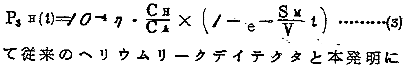 用いるヘリ ウム リークディテクタとは、 絞り弁 2と透過膜 6との違いを除いて他の 全ての諸条件が同一とした場合、 S V = S Mとなる。 そして透過膜 6 にサンブルガスを透過させることによって、 従来の絞り弁 2 を用 いた場合に比較して、 本癸明は C H / C A倍のヘリ ゥム分圧比が得 られることが判る。 , . If S «>> CA and SM >> C s, equation ( 2 ) becomes equation ( 3 ) below. The helium leak detector to be used is SV = SM when all other conditions are the same except for the difference between the throttle valve 2 and the permeable membrane 6. Then, it can be seen that by permeating the sam- ble gas through the permeable membrane 6, compared to the case where the conventional throttle valve 2 is used, the present invention can obtain a CH / CA doubled partial pressure ratio. ,.
本発明は前述した知見に基づく ものであり、 比較的高いへリ ウム 分圧の変化によってシステムの漏洩を検知できるし、 システムの瀉 洩を検知する装置が小形になる利点が得られる。 また透過膜 6はフ ィルターの役割をも杲すので、 質量分析管 5がダス トヒューム等に よって污染されることを防止することができる利点も得られる。 The present invention is based on the above-described findings, and has the advantage that a system leak can be detected by a relatively high change in helium partial pressure, and a device for detecting system leak can be downsized. Further, since the permeable membrane 6 also plays a role of a filter, an advantage that the mass spectrometer tube 5 can be prevented from being infected by dust fume or the like can be obtained.
第 J図〜第 図は、 本発明の代表的な^つの実施例を示したもの である FIGS. J to J show representative embodiments of the present invention.
第 3図において、 システム Aは、 例えば真空用あるいは高圧用に 用いられるタンクあるいは配管等である。 ヘリ ゥムリークディテク タ Bは、 テス トボー ト 1と拡散ボンブ 8 と質量分析管 5 と透過膜 6 と絞り弁 7 , 8 , 9 とロータ リ ボンブ 1 0 , 1 1 とを具備している。 システム Aには、 ヘ リ ウム リ ークディテク タ と主排気ポンプ 2 1 とが各々配管 2 2 , 2 3を介して接続されている。 あるいは披線で 示す配管 2 4によって、 システム Aの主排気ボートと検 ffiボー ト_と
を共甩させても良い。 主排気ポンプ 2 1は、 例えば ータ リ ボンブ 等の真空ボンブであり、 システム A内を所定の低真空圧まで排気す る O In FIG. 3, system A is, for example, a tank or piping used for vacuum or high pressure. The heavy leak detector B includes a test boat 1, a diffusion bomb 8, a mass spectrometer tube 5, a permeable membrane 6, throttle valves 7, 8, 9 and rotary bombs 10, 11. A helium leak detector and a main exhaust pump 21 are connected to the system A via pipes 22 and 23, respectively. Alternatively, the main exhaust boat of System A and the inspection boat_ May be shared. The main exhaust pump 21 is a vacuum bomb such as a gas bomb, and evacuates the system A to a predetermined low vacuum pressure.
—方、 システム Aに漏洩個所があると、 この個所から空気がシス テム Aに流入し、 排気速度に関連してシステム A内の真空度が一定 となる。 その後、 システム Aの外壁にヘリ ゥムが吹きつけられる。 ヘリ ゥムが吹きつけられた場所が漏洩個所であると、 その懾所から ヘリ ゥムが空気と置換してシステム Aに流入し、 システム A内の残 存ガスのヘリ ゥム分圧が高められる。 このヘリ ゥム分圧が高められ た残存ガス (サンブルガス) は、 排気されることによって配管 2 2 あるいは 2 4を通ってテス トボー ト 1に流入する。 On the other hand, if there is a leak in System A, air will flow into System A from this location, and the degree of vacuum in System A will be constant in relation to the pumping speed. After that, a helmet is sprayed on the outer wall of System A. If the location where the helicopter was blown is a leak location, the helicopter replaces air from that location and flows into system A, and the partial pressure of the residual gas in system A increases. Can be The residual gas (SAMBLE gas) having the increased partial pressure of the helium flows into the test boat 1 through the pipe 22 or 24 by being exhausted.
テス トボ, ト 1に流入したサンブルガスは、 絞り弁 7を絰由した 後、 透過膜 6を通って質量分析管 5に導かれる。 透過膜 6を通過後 のサンブルガスのヘリ ゥム分圧比は、 透過膜 6によって、 透過膜 6 を通過前のサンブルガスのヘリ ゥム分圧比よ り高められており、 こ の通過後のヘリ ゥム分圧比が質量分析管 5に至って感知され、 次い で絞り弁 8を経て拡散ホ'ンブ 8および ータ リ ポンブ 1 0によって 排気される。 ここで質量分析管 5中の真空度は絞り弁 7 および 8に よ り篛整される。 なおロータ リ ボンブ 1 1は透過膜 6に流入するサ ンブルガスを置換するためのものであり 、 絞り弁 9は同ホ 'ンブ 1 1 の実効排気速度を調整するために設けられたものである。 After flowing through the throttle valve 7, the sample gas flowing into the test boat 1 is guided to the mass spectrometer tube 5 through the permeable membrane 6. The helical gas partial pressure ratio of the sample gas after passing through the permeable membrane 6 is higher than the helical gas partial pressure ratio of the sample gas before passing through the permeable film 6 by the permeable membrane 6, and the The steam partial pressure ratio is sensed up to the mass spectrometer tube 5, and then exhausted by the diffusion horn 8 and the rotary pump 10 via the throttle valve 8. Here, the degree of vacuum in the mass spectrometer tube 5 is adjusted by the throttle valves 7 and 8. The rotary bomb 11 is for replacing the sample gas flowing into the permeable membrane 6, and the throttle valve 9 is provided for adjusting the effective pumping speed of the same.
別の方法と して、 ロータ リ ボンブ 1 1 をロータ リ ボンブ 1 0に共 用しても良い。 この場合、 絞り弁 9以後の 15管が拡散ボンブ 3 と《 —タ リ ポン プ 1 0 とを結ぶ配管 4に連設される。 また、 ロ ータ リ ホ- ンブ 1 1は透過膜 6に流入するサンブルガスの圧力に応じて他の真
空ポンプあるいは吸込ボンブに代えることも可能である。 As another method, the rotary bomb 11 may be shared with the rotary bomb 10. In this case, fifteen pipes after the throttle valve 9 are connected to the pipe 4 connecting the diffusion bomb 3 and the <<-tali pump 10. Further, the rotary horn 11 is provided with another true depending on the pressure of the sample gas flowing into the permeable membrane 6. It is also possible to substitute an empty pump or a suction bomb.
第 3図の実施例は、 システムの漏洩が大きいとき、 すなわちシス テム内が高真空を維 できないときの検知方法として有効である。 例えば、 システム内の圧力が/ —1 Tor rで、 その内のヘリ ゥム濃 度が/^ク ppmであり、 質量分析管内の圧力が/ -sTorrであった 場合、 従来の方法では質量分析管内のへリ.ゥム分圧が/ ^一》Tor r であった。 しかるに第 3 ^に示すへリ ゥムリークディテクタを用い、 さらにヘリ ゥムのコ ン ダク タ ンスが / X / 0→ ミ、 ';空 のコ ンダ クタンスが X / 0一 e /sの透過膜を用いた場合、 淀来の方法 と比べて/秒後でゾ 倍、 秒後で 倍のヘリ ゥム分圧が得られ た o . . The embodiment of FIG. 3 is effective as a detection method when the system has a large leak, that is, when a high vacuum cannot be maintained in the system. For example, the pressure in the system / - 1 Tor r, a helicopter © beam concentration is / ^ click ppm of which, the pressure in the mass spectrometer tube is / - when was s Torr, in the conventional method by weight The partial pressure of the air in the analytical tube was / ^-1 >> Tor r. However, using the leak leak detector shown in 3 ^, the conductance of the vehicle is / X / 0 → M, '; the transmissive film has an empty conductance of X / 0.1e / s. O, the partial pressure of the helium was doubled after / second and twice as high as that of the solitary method.
第 図の実施例は、 システム A内のサンプルガスを挞散ボンブ 31 およびロータ リ ボンブ 3 2によって排気すると共に、 拡散ボンブ 31 の背圧側に管 8' 8を介して第 3図の実施例に示したヘリ ゥム リ,ク ディテクタ Bを連設して、 システムの漏洩を検知するようにしたも のであり、 第 3図の実施例と同様の劫杲が得られる。 In the embodiment shown in FIG. 3, the sample gas in the system A is exhausted by the diffusion bomb 31 and the rotary bomb 32, and the pipe 8'8 is connected to the back pressure side of the diffusion bomb 31 through the pipe 8'8. The helicopter and detector B shown in the figure are connected in series to detect system leaks, and the same ghost as in the embodiment shown in Fig. 3 can be obtained.
本発明はシステムに加圧へリ ゥムを封入して同システムの漏洩を 検知することができる。 According to the present invention, a pressurized room is sealed in a system, and leakage of the system can be detected.
第 図の実施例は、 システム Aにヘリ ゥムあるいはヘリ ゥムを主 成分とする混合ガスを大気圧以上に加圧して封入し (斜籙は加圧状 態を示している) 、 ヘリ ウムリークディテクタ Bのテス トボー ト 1 に真空ホース 4 1の一凝を接続し、 同真空ホース 4 1の他嬙に接続 されたスニ ファーノ ズル 4 2によってシステム Aの外部に漏洩する ヘリ ゥムを検知する方法である。 この方法は通常のスニ ファー法を 応用したものである。 钹来、 この方法に使用されたス-ファーノズ In the embodiment shown in FIG. 5, a helium or a mixed gas containing a helium as a main component is pressurized and filled to a pressure higher than the atmospheric pressure in system A (the slant indicates a pressurized state). A test hose 1 of leak detector B is connected to a vacuum hose 41, and a sniffer nozzle 42 connected to the other end of the vacuum hose 41 detects a leaked vehicle outside system A. How to This method is an application of the usual sniffer method. Ever since, this method was used by Sfurnos
CMPI
ルは、 大気圧とへり ゥムリークディテク タの高真空圧との圧力差を 保つ必要上、 その先端は微細な孔をもった構造となっているため、 ダス ト等が詰まる不都合があった。 CMPI Since the pressure difference between the atmospheric pressure and the high vacuum pressure of the hem leak detector must be maintained, the tip has a structure with fine holes, so there was an inconvenience that dust and the like became clogged. .
しかし本発明によれば、 スニ フアーノ ズルの先鍚瓿は比較的大き な孔で構成できるので、 ダス ト等の目詰りの不芻合を解消し得ると 共に検知能力が格段に向上することができる。 例えば、 システム内 にヘリ ゥムを加圧して封入した後、 質量分析管内を/ T o r rの 高真空圧を保ちへリ ゥムのコンダクタンスが / X / 0 ~* JL 、 空気 のコンダク タ ンスがズ 《2 X / ー 8 Zsの透過腠を用いて第 図に 示すように実施した処、 質'量分析管内のへリ ゥム分圧を /移 JK下 の応答時間で淀来より約 倍高めることができた。 ま *たス - ファ 一ノ ズルの代りに、 ヘリ ゥムを選択的に透過させる透過膜が形成さ れた検出器を用いても良い。 この検出器は、 例えば筒^の先端部に 拔壁状の切欠を形成し、 筒状の内部に透遏膜を設けたものである。 However, according to the present invention, since the tip of the sniffer nozzle can be constituted by a relatively large hole, it is possible to eliminate the inconvenience of clogging such as dust and to improve the detection capability remarkably. it can. For example, after pressurizing and enclosing the helium in the system, the mass spectrometer maintains a high vacuum pressure of / Torr, the realm conductance is / X / 0 ~ * JL, and the air conductance is processing was carried out as shown in FIG using transmission腠of's "2 X / over 8 Zs, about fold from Yodo come re © beam partial pressure to the quality 'weight analysis tube / transfer JK response time under Could be enhanced. In addition, a detector having a permeable membrane for selectively transmitting a vehicle may be used instead of the spheroid nozzle. This detector has, for example, a cutout in the shape of a drawn wall at the tip of a tube, and a permeation membrane provided inside the tube.
次に第^図の実施例は、 システムが比較的高真空圧状態を錐持で きる場合に適した方法である。 すなわち、 ステム A内の排気を管 5 1を介してへリ ゥム リークディテク タ Cのみで行うか、 あるいは 管 5 2で連設された拡散ボンブ 5 3およびロータ リ ボンブ 5 4から なる別途の排気装置を作動させながら漏洩を検知する方法である。 Next, the embodiment of FIG. 3 is a method suitable for a case where the system can maintain a relatively high vacuum pressure state. In other words, the exhaust in the stem A is performed only by the leak detector C via the pipe 51, or a separate exhaust pipe consisting of the diffusion bomb 53 and the rotary bomb 54 connected by the pipe 52 is used. This is a method of detecting leakage while operating the exhaust device.
テス トボー ト 1からヘリ ゥムリ ークディテク タ C内に流入したサ ンブルガスは絞り弁 5 5を通って挞散ボンブ 3に吸引され、 次いで w—タ リ ボンブ 1 0によって排気される。 拭散ポンプ 3 とロータ リ ポンプ 1 0 との間のサンブルガスはその一部が透過膜 6 を透過する ことによってヘリ ゥム分圧比が高められ、 このヘリ ゥム分圧比が高 められたガスは分岐回路 5 6を流れて質量分析管 5に感知される-。
このガス'は、 絞り弁 5 7を通って再び拡散ボンブ 3 に吸引される。 なお絞り弁 5 7は貧量分析管に対する拡散ホ 'ンブ 8 の実効排気速度 を調整するためのものである o The sample gas flowing into the leak detector C from the test boat 1 is sucked into the diffusion bomb 3 through the throttle valve 55 and then exhausted by the w-bomb 10. A part of the sample gas between the wiping pump 3 and the rotary pump 10 permeates the permeable membrane 6 to increase the partial pressure ratio of the helium gas. Flows through the branch circuit 56 and is detected by the mass spectrometer 5. This gas is sucked into the diffusion bomb 3 again through the throttle valve 57. The throttle valve 57 is used to adjust the effective pumping speed of the diffusion chamber 8 for the poor analysis tube.o
以上説明したように本発明は、 空気に比べてヘリ ゥムを選択的に 透過させ得る透過膜にサンプルガスを透過させてへリ ゥム分圧比が 高められたガスのヘ リ ゥム分圧を質量分析管によって検知させるこ とを特徵としている。 As described above, according to the present invention, the sample gas is transmitted through a permeable membrane that can selectively transmit the air in comparison with air, and the partial pressure ratio of the gas is increased. Is detected by a mass spectrometer tube.
使^される透過膜としては、 比較的ヘリ ゥムと空気に対する分離 係数 (ヘリ ゥムの透逼率+空気の透遏率) が大きく 、 かつヘリ ゥム の透過率が少なく ともコ ンダクタンスに換算して / -4 A/s j¾上あ るものが望ましい。 また薄膜加工が容易に可能なものが.望ましいが、 このような条仵を漓たすものとしてはポリスチレン等の高分子膜が 有效であった o The permeable membrane used has a relatively large separation coefficient (helium tightness + air permeability) for the helium and air, and has a low conductance at least for the helical permeability. Convert to / - 4 A / s j¾ wear shall be desirable. It is also desirable to be able to process thin films easily, but a polymer film such as polystyrene was effective as a means to meet such requirements.
次に、 本発明の作用効果を下記に示す。 Next, the operation and effect of the present invention will be described below.
透過膜によってサンブルガス内のヘリ ゥム分圧比が高められて質 量分析管によって検知できるので、 検知感度が著るしく向上し、 ま た検出精度も向上する。 透過膜がもつフィルタ效果によって、 質量 分析管内を常に清浄に保つことができ信頼铨も向上する。 また徴鈿 な毛細管をもつ絞り弁やス - フアーノズルを使用する必要が少ない ため、 ダス ト等による目詰りによって生じた不都合を全く解消でき る O Since the permeable membrane increases the partial pressure ratio of the helium gas in the sam- ble gas and can be detected by the mass spectrometer tube, the detection sensitivity is remarkably improved and the detection accuracy is also improved. Due to the filter effect of the permeable membrane, the inside of the mass spectrometer tube can always be kept clean, and the reliability is improved. In addition, since it is not necessary to use a throttle valve or a water nozzle having a raden capillary, the inconvenience caused by clogging due to dust can be completely eliminated.
更に大きな効果としては、 ヘリ ゥムリークディテクタが備える排 気系を小さくできることである o 例えぱ従来の方法では、 排気速度 が/ 〜《2 sの拡散ボンブと、 同拡散ボンブの背圧を排気する と共に排気速度が/ 〜《2 ヱ ^のロータ リ ボンブとが必要であ-る
(ID An even greater effect is that the exhaust system of the leak detector can be reduced.o For example, with the conventional method, the exhaust speed is / ~ << 2 s diffusion bomb and the back pressure of the diffusion bomb is exhausted. It is necessary to have a rotary bomb with a pumping speed of ~ 2 << ^ (ID
が、 本発明を適用すると、 / /Sの拡散ボンブと / Ji/wk 口一タ リ ポンプとで済むのでヘリ ゥムリ ークディテクタを著るしく小型化で き 43 0 However, when the present invention is applied, it is sufficient to use only a / S diffusion bomb and a / Ji / wk one-way pump, so that the size of the leak detector can be significantly reduced.
産棻上の利甩可能铨 Industrial availability
以上のよ うに、 本発明の方法によれば、 真空をあっかうシステム 例えばタ ンクおよび記管等の漏洩を検知するのに有甩である。 また 他の気密を有するシステム例えば高圧タ ンク、 高圧用の記管等の漏 洩の検査に用いても良い O
As described above, according to the method of the present invention, it is useful for detecting a leak in a vacuum trapping system such as a tank and a storage tube. It may also be used for inspection of other airtight systems such as high pressure tanks, high pressure storage tubes, etc.
Claims
請 求 の 範 囲 The scope of the claims
/ システムからのサンブルガスを、 ヘ リ ウムを選択的に透過させ る透遏膜に透遏させて、 ヘリ ウム成分を増大させた後、 ヘリ ウム リ ークディ テク タによって感知してシステムの漏洩を検知するよ うにしたヘリ ゥムを用いてシステムの漏筏を検知する方法。 / After increasing the helium content by passing permeation from the system through a permeation membrane that selectively permeates helium, the system leaks as detected by a helium leak detector. A method of detecting leaky rafts in a system using a helicopter.
前記透過膜は、 高分子膜である特許請求の範囲第/項記載の方 The method according to claim 1, wherein the permeable membrane is a polymer membrane.
? i o ? i o
a 前記高分子膜は、 ボリ スチレン膜である特許請求の範囲第 項 記載の方法 o a the polymer film is a polystyrene film;
4 前記サ ンブルガスは低真空圧のガスであり、 また .f¾記へリ ウム リ クディテクタの検知部では窩真空圧である特許請求の範囲第 /項から第 項までのいずれかに記載の方法。 4. The method according to any one of claims 1 to 3, wherein the sample gas is a gas having a low vacuum pressure, and wherein the detection portion of the helium detector has an open vacuum pressure.
前記サンブルガスは、 システムにヘリ ウムを含むガスを加圧し て封入し、 同システムから漏洩し得るヘリ ウムを含む混合ガスと、 同システムの外壁瓿分の空気とからなる特許請求の粽囲第/項か ら第 3項までのいずれかに記載の方法。 The said shamble gas comprises a gas containing helium, which is pressurized and sealed in the system, and a mixture gas containing helium that can leak from the system and air sufficient for the outer wall of the system. The method according to any of paragraphs 3 to 3.
k 前記サンブルガスは、 ス -ファーノ ズルによって採取された特 許請求の範囲第 項記載の方法 o k The method according to claim 5, wherein said sample gas is collected by S-Fanozzur
7. 前記サンブルガスは、 透過膜を用いた検 ίίί器によって採取され た特許請求の範囲第 項記載の方法。 7. The method according to claim 1, wherein the sample gas is collected by a detector using a permeable membrane.
8i 前記透過膜は、 高分子膜である特許請求の範囲第 7項記載の方 法 O 8i The method according to claim 7, wherein the permeable membrane is a polymer membrane.
?. 前記高分子膜は、 ボリ スチレン膜である特許請求の範囲第 f 項 記載の方法。
?. The method according to claim f, wherein the polymer film is a polystyrene film.
Priority Applications (1)
| Application Number | Priority Date | Filing Date | Title |
|---|---|---|---|
| DE8181900554T DE3176358D1 (en) | 1980-03-10 | 1981-03-06 | Leakage detection method using helium |
Applications Claiming Priority (2)
| Application Number | Priority Date | Filing Date | Title |
|---|---|---|---|
| JP80/29946 | 1980-03-10 | ||
| JP2994680A JPS56126733A (en) | 1980-03-10 | 1980-03-10 | Detecting method for leakage of helium |
Publications (1)
| Publication Number | Publication Date |
|---|---|
| WO1981002631A1 true WO1981002631A1 (en) | 1981-09-17 |
Family
ID=12290145
Family Applications (1)
| Application Number | Title | Priority Date | Filing Date |
|---|---|---|---|
| PCT/JP1981/000048 WO1981002631A1 (en) | 1980-03-10 | 1981-03-06 | Leakage detection method using helium |
Country Status (5)
| Country | Link |
|---|---|
| US (1) | US4419882A (en) |
| EP (1) | EP0047324B1 (en) |
| JP (1) | JPS56126733A (en) |
| DE (1) | DE3176358D1 (en) |
| WO (1) | WO1981002631A1 (en) |
Cited By (1)
| Publication number | Priority date | Publication date | Assignee | Title |
|---|---|---|---|---|
| CN116558730A (en) * | 2023-07-10 | 2023-08-08 | 华能淮阴第二发电有限公司 | Portable unit vacuum system leak hunting device |
Families Citing this family (32)
| Publication number | Priority date | Publication date | Assignee | Title |
|---|---|---|---|---|
| GB2123153A (en) * | 1982-06-30 | 1984-01-25 | Boc Group Plc | Leak detector |
| US4558587A (en) * | 1984-08-29 | 1985-12-17 | Varian Associates, Inc. | Ball-type vacuum valve for leak detection apparatus |
| US4785666A (en) * | 1986-12-19 | 1988-11-22 | Martin Marietta Corporation | Method of increasing the sensitivity of a leak detector in the probe mode |
| EP0365042A1 (en) * | 1987-03-31 | 1990-04-25 | FINN-AQUA SANTASALO-SOHLBERG GmbH | Method for monitoring leakage in liquid conduit systems of cold drying equipment and adapted cold drying equipment for carrying out this method |
| US5022265A (en) * | 1987-03-31 | 1991-06-11 | Finn-Aqua | Method and apparatus for leak testing fluid conducting freeze-drying apparatus |
| FR2653558B1 (en) * | 1989-10-23 | 1994-06-10 | Cit Alcatel | TRACER GAS LEAK DETECTION SYSTEM. |
| DE9202350U1 (en) * | 1992-02-24 | 1992-04-16 | Leybold Ag, 6450 Hanau, De | |
| DE4228085A1 (en) * | 1992-08-24 | 1994-03-03 | Leybold Ag | Method and device for detecting a light test gas in a liquid |
| JPH0661680U (en) * | 1993-02-04 | 1994-08-30 | 光雄 柳澤 | Automatic bicycle with low bed |
| DE4326267A1 (en) * | 1993-08-05 | 1995-02-09 | Leybold Ag | Leak detector |
| DE4326264A1 (en) * | 1993-08-05 | 1995-02-09 | Leybold Ag | Test gas detector with vacuum pump and method for operating a test gas detector of this type |
| US5375456A (en) * | 1993-11-18 | 1994-12-27 | Trw Vehicle Safety Systems Inc. | Leak testing apparatus and method |
| SE502355C2 (en) * | 1994-02-17 | 1995-10-09 | Hans Stymne | Set and device to deliver small amounts of gas from a substance in condensed form to the environment at a controlled rate |
| EP0718613B1 (en) * | 1994-12-23 | 2003-03-05 | Unaxis Balzers Aktiengesellschaft | Method for analysing gas and gas analyser |
| FR2734633B1 (en) * | 1995-05-24 | 1997-06-20 | Cit Alcatel | INSTALLATION FOR DETECTING THE PRESENCE OF HELIUM IN A FLUID CIRCUIT |
| US6401465B1 (en) * | 2000-10-19 | 2002-06-11 | Carrier Corporation | Absorption chiller leak detection and location and checking hydrogen removing cells |
| JP2004521057A (en) * | 2000-12-22 | 2004-07-15 | エムイーエムシー・エレクトロニック・マテリアルズ・インコーポレイテッド | A process for monitoring the gaseous environment of a crystal puller for semiconductor growth. |
| SE518522C2 (en) * | 2001-03-21 | 2002-10-22 | Sensistor Ab | Method and device for leakage testing and leak detection |
| DE10324596A1 (en) * | 2003-05-30 | 2004-12-16 | Inficon Gmbh | Leak Detector |
| DE102004045803A1 (en) * | 2004-09-22 | 2006-04-06 | Inficon Gmbh | Leak test method and leak tester |
| DE102005021909A1 (en) * | 2005-05-12 | 2006-11-16 | Inficon Gmbh | Sniffer leak detector with quartz window sensor |
| US20080202210A1 (en) * | 2007-02-28 | 2008-08-28 | Varian, Inc. | Test gas leak detection using a composite membrane |
| US7497110B2 (en) * | 2007-02-28 | 2009-03-03 | Varian, Inc. | Methods and apparatus for test gas leak detection |
| US7905132B1 (en) | 2007-08-14 | 2011-03-15 | LACO Technologies, Inc. | Leak testing using tracer gas permeable membrane |
| US9429494B1 (en) | 2012-11-21 | 2016-08-30 | Western Digital Technologies, Inc. | Leakage test method for a hermetically sealed disk drive enclosure |
| CN103175662A (en) * | 2013-03-20 | 2013-06-26 | 厦门松芝汽车空调有限公司 | Leak detecting method in production of large and medium-sized automobile air conditioner |
| RU2560109C2 (en) * | 2013-09-30 | 2015-08-20 | Открытое акционерное общество "Моринформсистема-Агат-КИП" | Control method of tightness of fuel element jackets |
| CN104913193B (en) * | 2015-06-30 | 2016-10-26 | 宜昌江峡船用机械有限责任公司 | The leak hunting method of a kind of interlayer low-temperature (low temperature) vessel inner pressurd vessel and device |
| CN105092182A (en) * | 2015-08-14 | 2015-11-25 | 中广核工程有限公司 | Vacuum helium leak checking method for condenser at power operation phase of nuclear power plant |
| CN107389498B (en) * | 2017-07-07 | 2024-01-12 | 金华职业技术学院 | Method for measuring methane transmittance |
| EP3814164A4 (en) * | 2018-06-29 | 2022-03-02 | Hyperloop Transportation Technologies, Inc. | Tube transportation systems using a gaseous mixture of air and helium |
| CN112098008A (en) * | 2020-08-25 | 2020-12-18 | 广东鸿图科技股份有限公司 | Device for detecting air tightness of workpiece |
Citations (1)
| Publication number | Priority date | Publication date | Assignee | Title |
|---|---|---|---|---|
| JPS462709Y1 (en) * | 1967-08-11 | 1971-01-29 |
Family Cites Families (8)
| Publication number | Priority date | Publication date | Assignee | Title |
|---|---|---|---|---|
| FR1181312A (en) * | 1957-08-20 | 1959-06-15 | Commissariat Energie Atomique | Improvement in sealing measurement methods |
| DE1648367A1 (en) * | 1967-06-05 | 1971-04-15 | Varian Mat Gmbh | Diffusion membrane arrangement, especially for leak detection tubes |
| US3591827A (en) * | 1967-11-29 | 1971-07-06 | Andar Iti Inc | Ion-pumped mass spectrometer leak detector apparatus and method and ion pump therefor |
| FR2058661A5 (en) * | 1969-09-19 | 1971-05-28 | Commissariat Energie Atomique | |
| FR2082765A5 (en) * | 1970-03-26 | 1971-12-10 | Commissariat Energie Atomique | |
| US3867631A (en) * | 1972-09-28 | 1975-02-18 | Varian Associates | Leak detection apparatus and inlet interface |
| FR2207598A5 (en) * | 1972-11-17 | 1974-06-14 | Veeco Sa | Mass spectrometry leak testing - is rapid and does not impose mechanical stresses of vacuum testing |
| DE2926112A1 (en) * | 1979-06-28 | 1981-01-08 | Bosch Gmbh Robert | Test leak probe for seal testing etc. - samples permeation of test gas through membrane to mass spectrometer |
-
1980
- 1980-03-10 JP JP2994680A patent/JPS56126733A/en active Granted
-
1981
- 1981-03-06 DE DE8181900554T patent/DE3176358D1/en not_active Expired
- 1981-03-06 WO PCT/JP1981/000048 patent/WO1981002631A1/en not_active Application Discontinuation
- 1981-03-06 US US06/325,435 patent/US4419882A/en not_active Expired - Lifetime
- 1981-03-06 EP EP81900554A patent/EP0047324B1/en not_active Expired
Patent Citations (1)
| Publication number | Priority date | Publication date | Assignee | Title |
|---|---|---|---|---|
| JPS462709Y1 (en) * | 1967-08-11 | 1971-01-29 |
Non-Patent Citations (1)
| Title |
|---|
| See also references of EP0047324A4 * |
Cited By (2)
| Publication number | Priority date | Publication date | Assignee | Title |
|---|---|---|---|---|
| CN116558730A (en) * | 2023-07-10 | 2023-08-08 | 华能淮阴第二发电有限公司 | Portable unit vacuum system leak hunting device |
| CN116558730B (en) * | 2023-07-10 | 2023-09-19 | 华能淮阴第二发电有限公司 | Portable unit vacuum system leak hunting device |
Also Published As
| Publication number | Publication date |
|---|---|
| EP0047324B1 (en) | 1987-08-12 |
| EP0047324A1 (en) | 1982-03-17 |
| US4419882A (en) | 1983-12-13 |
| JPS56126733A (en) | 1981-10-05 |
| EP0047324A4 (en) | 1983-12-23 |
| DE3176358D1 (en) | 1987-09-17 |
| JPS6249923B2 (en) | 1987-10-22 |
Similar Documents
| Publication | Publication Date | Title |
|---|---|---|
| WO1981002631A1 (en) | Leakage detection method using helium | |
| US4499752A (en) | Counterflow leak detector with cold trap | |
| US4472962A (en) | Low pressure leak detector | |
| US4779449A (en) | Leak detector and leak detection method | |
| EP0356877B1 (en) | Process for controlling the tightness of a test container using a tracer gas | |
| US11105704B2 (en) | Method and apparatus for an integrity test of a flexible container with inspection fluid | |
| EP1596066A1 (en) | Light gas vacuum pumping system | |
| US5375456A (en) | Leak testing apparatus and method | |
| JPH0674855A (en) | Vacuum leakage detection method and device | |
| JP2020008564A (en) | Device, method, usage for leak detection, and corresponding computer program storage means | |
| JP2635587B2 (en) | Device for calibrating the detector of the leak inspection device | |
| JP5575812B2 (en) | How to functionally test a leak detector | |
| JP4037954B2 (en) | Tracer gas leak detector | |
| GB2190204A (en) | Search gas leak detector | |
| CN107179163A (en) | The high speed suction gun leak detecting device and detection method of high-power transformer potted component | |
| RU1809919C (en) | Device for detecting leaks using indicator gas | |
| JP4374241B2 (en) | System and method for measuring the sealability of an object | |
| US20220181709A1 (en) | Tightness test of a liquid filled test object | |
| EP0475246B1 (en) | High flow leak detector with three molecular filters | |
| JPH04256817A (en) | Leakage testing apparatus | |
| CN116569015A (en) | Gas leakage detection device and gas leakage detection method for identifying gas leakage in test object | |
| JP2011069834A (en) | Helium leak detector | |
| JP2007198865A (en) | Helium leak detector | |
| US20180252613A1 (en) | Leak Detection Upon Evacuation of a Test Chamber or a Specimen | |
| JPH07103843A (en) | Method and equipment for detecting vacuum leakage |
Legal Events
| Date | Code | Title | Description |
|---|---|---|---|
| AK | Designated states |
Designated state(s): SU US |
|
| AL | Designated countries for regional patents |
Designated state(s): DE FR GB |
|
| WWE | Wipo information: entry into national phase |
Ref document number: 1981900554 Country of ref document: EP |
|
| WWP | Wipo information: published in national office |
Ref document number: 1981900554 Country of ref document: EP |
|
| WWG | Wipo information: grant in national office |
Ref document number: 1981900554 Country of ref document: EP |
|
| WWW | Wipo information: withdrawn in national office |
Ref document number: 1981900554 Country of ref document: EP |