USRE42678E1 - Reconfigurable optical add-drop multiplexers with servo control and dynamic spectral power management capabilities - Google Patents
Reconfigurable optical add-drop multiplexers with servo control and dynamic spectral power management capabilities Download PDFInfo
- Publication number
- USRE42678E1 USRE42678E1 US12/815,930 US81593010A USRE42678E US RE42678 E1 USRE42678 E1 US RE42678E1 US 81593010 A US81593010 A US 81593010A US RE42678 E USRE42678 E US RE42678E
- Authority
- US
- United States
- Prior art keywords
- wavelength
- channel
- output ports
- spectral
- spectral channels
- Prior art date
- Legal status (The legal status is an assumption and is not a legal conclusion. Google has not performed a legal analysis and makes no representation as to the accuracy of the status listed.)
- Ceased
Links
Images


Classifications
-
- G—PHYSICS
- G02—OPTICS
- G02B—OPTICAL ELEMENTS, SYSTEMS OR APPARATUS
- G02B6/00—Light guides; Structural details of arrangements comprising light guides and other optical elements, e.g. couplings
- G02B6/24—Coupling light guides
- G02B6/26—Optical coupling means
- G02B6/28—Optical coupling means having data bus means, i.e. plural waveguides interconnected and providing an inherently bidirectional system by mixing and splitting signals
- G02B6/293—Optical coupling means having data bus means, i.e. plural waveguides interconnected and providing an inherently bidirectional system by mixing and splitting signals with wavelength selective means
- G02B6/29379—Optical coupling means having data bus means, i.e. plural waveguides interconnected and providing an inherently bidirectional system by mixing and splitting signals with wavelength selective means characterised by the function or use of the complete device
- G02B6/2938—Optical coupling means having data bus means, i.e. plural waveguides interconnected and providing an inherently bidirectional system by mixing and splitting signals with wavelength selective means characterised by the function or use of the complete device for multiplexing or demultiplexing, i.e. combining or separating wavelengths, e.g. 1xN, NxM
- G02B6/29382—Optical coupling means having data bus means, i.e. plural waveguides interconnected and providing an inherently bidirectional system by mixing and splitting signals with wavelength selective means characterised by the function or use of the complete device for multiplexing or demultiplexing, i.e. combining or separating wavelengths, e.g. 1xN, NxM including at least adding or dropping a signal, i.e. passing the majority of signals
- G02B6/29385—Channel monitoring, e.g. by tapping
-
- G—PHYSICS
- G02—OPTICS
- G02B—OPTICAL ELEMENTS, SYSTEMS OR APPARATUS
- G02B6/00—Light guides; Structural details of arrangements comprising light guides and other optical elements, e.g. couplings
- G02B6/24—Coupling light guides
- G02B6/26—Optical coupling means
- G02B6/28—Optical coupling means having data bus means, i.e. plural waveguides interconnected and providing an inherently bidirectional system by mixing and splitting signals
- G02B6/293—Optical coupling means having data bus means, i.e. plural waveguides interconnected and providing an inherently bidirectional system by mixing and splitting signals with wavelength selective means
- G02B6/29304—Optical coupling means having data bus means, i.e. plural waveguides interconnected and providing an inherently bidirectional system by mixing and splitting signals with wavelength selective means operating by diffraction, e.g. grating
- G02B6/29305—Optical coupling means having data bus means, i.e. plural waveguides interconnected and providing an inherently bidirectional system by mixing and splitting signals with wavelength selective means operating by diffraction, e.g. grating as bulk element, i.e. free space arrangement external to a light guide
- G02B6/2931—Diffractive element operating in reflection
-
- G—PHYSICS
- G02—OPTICS
- G02B—OPTICAL ELEMENTS, SYSTEMS OR APPARATUS
- G02B6/00—Light guides; Structural details of arrangements comprising light guides and other optical elements, e.g. couplings
- G02B6/24—Coupling light guides
- G02B6/26—Optical coupling means
- G02B6/28—Optical coupling means having data bus means, i.e. plural waveguides interconnected and providing an inherently bidirectional system by mixing and splitting signals
- G02B6/293—Optical coupling means having data bus means, i.e. plural waveguides interconnected and providing an inherently bidirectional system by mixing and splitting signals with wavelength selective means
- G02B6/29304—Optical coupling means having data bus means, i.e. plural waveguides interconnected and providing an inherently bidirectional system by mixing and splitting signals with wavelength selective means operating by diffraction, e.g. grating
- G02B6/29305—Optical coupling means having data bus means, i.e. plural waveguides interconnected and providing an inherently bidirectional system by mixing and splitting signals with wavelength selective means operating by diffraction, e.g. grating as bulk element, i.e. free space arrangement external to a light guide
- G02B6/29313—Optical coupling means having data bus means, i.e. plural waveguides interconnected and providing an inherently bidirectional system by mixing and splitting signals with wavelength selective means operating by diffraction, e.g. grating as bulk element, i.e. free space arrangement external to a light guide characterised by means for controlling the position or direction of light incident to or leaving the diffractive element, e.g. for varying the wavelength response
-
- G—PHYSICS
- G02—OPTICS
- G02B—OPTICAL ELEMENTS, SYSTEMS OR APPARATUS
- G02B6/00—Light guides; Structural details of arrangements comprising light guides and other optical elements, e.g. couplings
- G02B6/24—Coupling light guides
- G02B6/26—Optical coupling means
- G02B6/28—Optical coupling means having data bus means, i.e. plural waveguides interconnected and providing an inherently bidirectional system by mixing and splitting signals
- G02B6/293—Optical coupling means having data bus means, i.e. plural waveguides interconnected and providing an inherently bidirectional system by mixing and splitting signals with wavelength selective means
- G02B6/29379—Optical coupling means having data bus means, i.e. plural waveguides interconnected and providing an inherently bidirectional system by mixing and splitting signals with wavelength selective means characterised by the function or use of the complete device
- G02B6/2938—Optical coupling means having data bus means, i.e. plural waveguides interconnected and providing an inherently bidirectional system by mixing and splitting signals with wavelength selective means characterised by the function or use of the complete device for multiplexing or demultiplexing, i.e. combining or separating wavelengths, e.g. 1xN, NxM
- G02B6/29382—Optical coupling means having data bus means, i.e. plural waveguides interconnected and providing an inherently bidirectional system by mixing and splitting signals with wavelength selective means characterised by the function or use of the complete device for multiplexing or demultiplexing, i.e. combining or separating wavelengths, e.g. 1xN, NxM including at least adding or dropping a signal, i.e. passing the majority of signals
- G02B6/29383—Adding and dropping
-
- G—PHYSICS
- G02—OPTICS
- G02B—OPTICAL ELEMENTS, SYSTEMS OR APPARATUS
- G02B6/00—Light guides; Structural details of arrangements comprising light guides and other optical elements, e.g. couplings
- G02B6/24—Coupling light guides
- G02B6/26—Optical coupling means
- G02B6/28—Optical coupling means having data bus means, i.e. plural waveguides interconnected and providing an inherently bidirectional system by mixing and splitting signals
- G02B6/293—Optical coupling means having data bus means, i.e. plural waveguides interconnected and providing an inherently bidirectional system by mixing and splitting signals with wavelength selective means
- G02B6/29379—Optical coupling means having data bus means, i.e. plural waveguides interconnected and providing an inherently bidirectional system by mixing and splitting signals with wavelength selective means characterised by the function or use of the complete device
- G02B6/29391—Power equalisation of different channels, e.g. power flattening
-
- G—PHYSICS
- G02—OPTICS
- G02B—OPTICAL ELEMENTS, SYSTEMS OR APPARATUS
- G02B6/00—Light guides; Structural details of arrangements comprising light guides and other optical elements, e.g. couplings
- G02B6/24—Coupling light guides
- G02B6/26—Optical coupling means
- G02B6/28—Optical coupling means having data bus means, i.e. plural waveguides interconnected and providing an inherently bidirectional system by mixing and splitting signals
- G02B6/293—Optical coupling means having data bus means, i.e. plural waveguides interconnected and providing an inherently bidirectional system by mixing and splitting signals with wavelength selective means
- G02B6/29379—Optical coupling means having data bus means, i.e. plural waveguides interconnected and providing an inherently bidirectional system by mixing and splitting signals with wavelength selective means characterised by the function or use of the complete device
- G02B6/29395—Optical coupling means having data bus means, i.e. plural waveguides interconnected and providing an inherently bidirectional system by mixing and splitting signals with wavelength selective means characterised by the function or use of the complete device configurable, e.g. tunable or reconfigurable
-
- G—PHYSICS
- G02—OPTICS
- G02B—OPTICAL ELEMENTS, SYSTEMS OR APPARATUS
- G02B6/00—Light guides; Structural details of arrangements comprising light guides and other optical elements, e.g. couplings
- G02B6/24—Coupling light guides
- G02B6/26—Optical coupling means
- G02B6/35—Optical coupling means having switching means
- G02B6/351—Optical coupling means having switching means involving stationary waveguides with moving interposed optical elements
- G02B6/3512—Optical coupling means having switching means involving stationary waveguides with moving interposed optical elements the optical element being reflective, e.g. mirror
-
- G—PHYSICS
- G02—OPTICS
- G02B—OPTICAL ELEMENTS, SYSTEMS OR APPARATUS
- G02B6/00—Light guides; Structural details of arrangements comprising light guides and other optical elements, e.g. couplings
- G02B6/24—Coupling light guides
- G02B6/26—Optical coupling means
- G02B6/35—Optical coupling means having switching means
- G02B6/3586—Control or adjustment details, e.g. calibrating
- G02B6/3588—Control or adjustment details, e.g. calibrating of the processed beams, i.e. controlling during switching of orientation, alignment, or beam propagation properties such as intensity, size or shape
-
- G—PHYSICS
- G02—OPTICS
- G02B—OPTICAL ELEMENTS, SYSTEMS OR APPARATUS
- G02B26/00—Optical devices or arrangements for the control of light using movable or deformable optical elements
- G02B26/08—Optical devices or arrangements for the control of light using movable or deformable optical elements for controlling the direction of light
- G02B26/0816—Optical devices or arrangements for the control of light using movable or deformable optical elements for controlling the direction of light by means of one or more reflecting elements
- G02B26/0833—Optical devices or arrangements for the control of light using movable or deformable optical elements for controlling the direction of light by means of one or more reflecting elements the reflecting element being a micromechanical device, e.g. a MEMS mirror, DMD
-
- G—PHYSICS
- G02—OPTICS
- G02B—OPTICAL ELEMENTS, SYSTEMS OR APPARATUS
- G02B6/00—Light guides; Structural details of arrangements comprising light guides and other optical elements, e.g. couplings
- G02B6/24—Coupling light guides
- G02B6/26—Optical coupling means
- G02B6/32—Optical coupling means having lens focusing means positioned between opposed fibre ends
-
- G—PHYSICS
- G02—OPTICS
- G02B—OPTICAL ELEMENTS, SYSTEMS OR APPARATUS
- G02B6/00—Light guides; Structural details of arrangements comprising light guides and other optical elements, e.g. couplings
- G02B6/24—Coupling light guides
- G02B6/26—Optical coupling means
- G02B6/34—Optical coupling means utilising prism or grating
-
- G—PHYSICS
- G02—OPTICS
- G02B—OPTICAL ELEMENTS, SYSTEMS OR APPARATUS
- G02B6/00—Light guides; Structural details of arrangements comprising light guides and other optical elements, e.g. couplings
- G02B6/24—Coupling light guides
- G02B6/26—Optical coupling means
- G02B6/35—Optical coupling means having switching means
- G02B6/354—Switching arrangements, i.e. number of input/output ports and interconnection types
- G02B6/3554—3D constellations, i.e. with switching elements and switched beams located in a volume
- G02B6/3556—NxM switch, i.e. regular arrays of switches elements of matrix type constellation
-
- G—PHYSICS
- G02—OPTICS
- G02B—OPTICAL ELEMENTS, SYSTEMS OR APPARATUS
- G02B6/00—Light guides; Structural details of arrangements comprising light guides and other optical elements, e.g. couplings
- G02B6/24—Coupling light guides
- G02B6/26—Optical coupling means
- G02B6/35—Optical coupling means having switching means
- G02B6/354—Switching arrangements, i.e. number of input/output ports and interconnection types
- G02B6/356—Switching arrangements, i.e. number of input/output ports and interconnection types in an optical cross-connect device, e.g. routing and switching aspects of interconnecting different paths propagating different wavelengths to (re)configure the various input and output links
-
- G—PHYSICS
- G02—OPTICS
- G02B—OPTICAL ELEMENTS, SYSTEMS OR APPARATUS
- G02B6/00—Light guides; Structural details of arrangements comprising light guides and other optical elements, e.g. couplings
- G02B6/24—Coupling light guides
- G02B6/26—Optical coupling means
- G02B6/35—Optical coupling means having switching means
- G02B6/3586—Control or adjustment details, e.g. calibrating
-
- G—PHYSICS
- G02—OPTICS
- G02B—OPTICAL ELEMENTS, SYSTEMS OR APPARATUS
- G02B6/00—Light guides; Structural details of arrangements comprising light guides and other optical elements, e.g. couplings
- G02B6/24—Coupling light guides
- G02B6/26—Optical coupling means
- G02B6/35—Optical coupling means having switching means
- G02B6/3592—Means for removing polarization dependence of the switching means, i.e. polarization insensitive switching
Definitions
- This invention relates generally to optical communication systems. More specifically, it relates to a novel class of dynamically reconfigurable optical add-drop multiplexers (OADMs) for wavelength division multiplexed optical networking applications.
- OADMs dynamically reconfigurable optical add-drop multiplexers
- Contemporary fiber-optic communications networks commonly employ wavelength division multiplexing (WDM), for it allows multiple information (or data) channels to be simultaneously transmitted on a single optical fiber by using different wavelengths and thereby significantly enhances the information-bandwidth of the fiber.
- WDM wavelength division multiplexing
- An optical add-drop multiplexer (OADM) serves to selectively remove (or drop) one or more wavelengths from a multiplicity of wavelengths on an optical fiber, hence taking away one or more data channels from the traffic stream on the fiber. It further adds one or more wavelength back onto the fiber, thereby inserting new data channels in the same stream of traffic.
- an OADM makes it possible to launch and retrieve multiple data channels (each characterized by a distinct wavelength) onto and from an optical fiber respectively, without disrupting the overall traffic flow along the fiber. Indeed, careful placement of the OADMs can dramatically improve an optical communication network's flexibility and robustness, while providing significant cost advantages.
- OADMs in the art typically employ multiplexers/demultiplexers (e.g. waveguide grating routers or arrayed-waveguide gratings), tunable filters, optical switches, and optical circulators in a parallel or serial architecture to accomplish the add and drop functions.
- a demultiplexer e.g., a waveguide grating router
- a wavelength switching/routing means e.g., a combination of optical switches and optical circulators
- a multiplexer combines the remaining (i.e., the pass-through) wavelengths into an output multi-wavelength optical signal.
- tunable filters e.g., Bragg fiber gratings
- optical circulators are used to separate the drop wavelength from the pass-through wavelengths and subsequently launch the add channels into the pass-through path.
- additional multiplexers and demultiplexers are required to demultiplex the drop wavelengths and multiplex the add wavelengths, respectively.
- the OADMs currently in the art are characteristically high in cost, and prone to significant optical loss accumulation.
- the designs of these OADMs are such that it is inherently difficult to reconfigure them in a dynamic fashion.
- U.S. Pat. No. 6,204,946 to Askyuk et al. discloses an OADM that makes use of free-space optics in a parallel construction.
- a multi-wavelength optical signal emerging from an input port is incident onto a ruled diffraction grating.
- the constituent spectral channels thus separated are then focused by a focusing lens onto a linear array of binary micromachined mirrors.
- Each micromirror is configured to operate between two discrete states, such that it either retrofits its corresponding spectral channel back into the input port as a pass-through channel, or directs its spectral channel to an output port as a drop channel.
- the pass-through signal (i.e., the combined pass-through channels) shares the same input port as the input signal.
- An optical circulator is therefore coupled to the input port, to provide necessary routing of these two signals.
- the drop channels share the output port with the add channels.
- An additional optical circulator is thereby coupled to the output port, from which the drop channels exit and the add channels are introduced into the output ports.
- the add channels are subsequently combined with the pass-through signal by way of the diffraction grating and the binary micromirrors.
- the aforementioned OADM disclosed by Askyuk et al. has the advantage of performing wavelength separating and routing in free space and thereby incurring less optical loss, it suffers a number of limitations.
- An optical circulator therefore has to be implemented, to provide necessary routing of these two signals.
- all the add and drop channels enter and leave the OADM through the same output port, hence the need for another optical circulator.
- additional means must be provided to multiplex the add channels before entering the system and to demultiplex the drop channels after exiting the system. This additional multiplexing/demultiplexing requirement adds more cost and complexity that can restrict the versatility of the OADM thus-constructed.
- the optical circulators implemented in this OADM for various routing purposes introduce additional optical losses, which can accumulate to a substantial amount.
- the constituent optical components must be in a precise alignment, in order for the system to achieve its intended purpose. There are, however, no provisions provided for maintaining the requisite alignment; and no mechanisms implemented for overcoming degradation in the alignment owing to environmental effects such as thermal and mechanical disturbances over the course of operation.
- U.S. Pat. No. 5,906,133 to Tomlinson discloses an OADM that makes use of a design similar to that of Aksyuk et al.
- each micromirror notwithstanding switchable between two discrete positions, either reflects its corresponding channel (coming from the input port) to the output port, or concomitantly reflects its channel to the drop port and an incident add channel to the output port.
- this OADM is able to perform both the add and drop functions without involving additional optical components (such as optical circulators and in the system of the Aksyuk et al.).
- the present invention provides a wavelength-separating-routing (WSR) apparatus and method which employ an array of fiber collimators serving as an input port and a plurality of output ports; a wavelength-separator; a beam-focuser; and an array of channel micromirrors.
- WSR wavelength-separating-routing
- a multi-wavelength optical signal emerges from the input port.
- the wavelength-separator separates the multi-wavelength optical signal into multiple spectral channels, each characterized by a distinct center wavelength and associated bandwidth.
- the beam-focuser focuses the spectral channels into corresponding spectral spots.
- the channel micromirrors are positioned such that each channel micromirror receives one of the spectral channels.
- the channel micromirrors are individually controllable and movable, e.g., continuously pivotable (or rotatable), so as to reflect the spectral channels into selected ones of the output ports.
- each channel micromirror is assigned to a specific spectral channel, hence the name “channel micromirror”.
- each output port may receive any number of the reflected spectral channels.
- a distinct feature of the channel micromirrors in the present invention is that the motion, e.g., pivoting (or rotation), of each channel micromirror is under analog control such that its pivoting angle can be continouously adjusted. This enables each channel micromirror to scan its corresponding spectral channel across all possible output ports and thereby direct the spectral channel to any desired output ports.
- the wavelength-separator may be provided by a ruled diffraction grating, a holographic diffraction grating, an echelle grating, a curved diffraction grating, a dispersing prism, or other wavelength-separating means known in the art.
- the beam-focuser may be a single lens, an assembly of lenses, or other beam-focusing means known in the art.
- the channel micromirrors may be provided by silicon micromachined mirrors, reflective ribbons (or membranes), or other types of beam-deflecting means known in the art. And each channel micromirror may be pivotable about one or two axes.
- the fiber collimators serving as the input and output ports may be arranged in a one-dimensional or two-dimensional array. In the latter case, the channel micromirrors must be pivotable biaxially.
- the WSR apparatus of the present invention may further comprise an array of collimator-alignment mirrors, in optical communication with the wavelength-separator and the fiber collimators, for adjusting the alignment of the input multi-wavelength signal and directing the spectral channels into the selected output ports by way of angular control of the collimated beams.
- Each collimator-alignment mirror may be rotatable about one or two axes.
- the collimator-alignment mirrors may be arranged in a one-dimensional or two-dimensional array.
- First and second arrays of imaging lenses may additionally be optically interposed between the collimator-alignment mirrors and the fiber collimators in a telecentric arrangement, thereby “imaging” the collimator-alignment mirrors onto the corresponding fiber collimators to ensure an optimal alignment.
- the WSR apparatus of the present invention may further include a servo-control assembly, in communication with the channel micromirrors and the output ports.
- the servo-control assembly serves to monitor the power levels of the spectral channels coupled into the output ports and further provide control of the channel micromirrors on an individual basis, so as to maintain a predetermined coupling efficiency of each spectral channel in one of the output ports.
- the servo-control assembly provides dynamic control of the coupling of the spectral channels into the respective output ports and actively manages the power levels of the spectral channels coupling into the output ports.
- the servo-control assembly may additionally provide dynamic control of the collimator-alignment mirrors.
- the utilization of such a servo-control assembly effectively relaxes the requisite fabrication tolerances and the precision of optical alignment during assembly of a WSR apparatus of the present invention, and further enables the system to correct for shift in optical alignment over the course of operation.
- a WSR apparatus incorporating a servo-control assembly thus described is termed a WSR-S apparatus, thereinafter in the present invention.
- the WSR-S (or WSR) apparatus of the present invention may be used to construct a variety of optical devices, including a novel class of dynamically reconfigurable optical add-drop multiplexers (OADMs), as exemplified in the following embodiments.
- OADMs dynamically reconfigurable optical add-drop multiplexers
- an OADM of the present invention comprises an aforementioned WSR-S (or WSR) apparatus and an optical combiner.
- the output ports of the WSR-S apparatus include a pass-through port and one or more drop ports, each carrying any number of the spectral channels.
- the optical combiner is coupled to the pass-through port, serving to combine the pass-through channels with one or more add spectral channels.
- the combined optical signal constitutes an output signal of the system.
- the optical combiner may be an N ⁇ 1 (N ⁇ 2) broadband fiber-optic coupler, for instance, which also serves the purpose of multiplexing a multiplicity of add spectral channels to be coupled into the system.
- a first WSR-S (or WSR) apparatus is cascaded with a second WSR-S (or WSR) apparatus.
- the output ports of the first WSR-S (or WSR) apparatus include a pass-through port and one or more drop ports.
- the second WSR-S (or WSR) apparatus includes a plurality of input ports and an exiting port. The configuration is such that the pass-through channels from the first WSR-S apparatus and one or more add channels are directed into the input ports of the second WSR-S apparatus, and consequently multiplexed into an output multi-wavelength optical signal directed into the exiting port of the second WSR-S apparatus.
- one WSR-S apparatus e.g., the first one
- the other WSR-R apparatus e.g., the second one
- the underlying OADM architecture thus presented is intrinsically scalable and can be readily extended to any number of the WSR-S (or WSR) systems, if so desired for performing intricate add and drop functions in a network environment.
- OADMs of the present invention provide many advantages over the prior art devices, notably:
- FIGS. 1A-1D show a first embodiment of a wavelength-separating-routing (WSR) apparatus according to the present invention, and the modeling results demonstrating the performance of the WSR apparatus;
- WSR wavelength-separating-routing
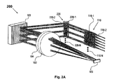
- FIGS. 2A-2C depict second and third embodiments of a WSR apparatus according to the present invention
- FIG. 3 shows a fourth embodiment of a WSR apparatus according to the present invention
- FIGS. 4A-4B show schematic illustration of two embodiments of a WSR-S apparatus comprising a WSR apparatus and a servo-control assembly, according to the present invention
- FIG. 5 depicts an exemplary embodiment of an optical add-drop multiplexer (OADM) according to the present invention.
- FIG. 6 shows an alternative embodiment of an OADM according to the present invention.
- spectral channel is characterized by a distinct center wavelength and associated bandwidth. Each spectral channel may carry a unique information signal, as in WDM optical networking applications.
- FIG. 1A depicts a first embodiment of a wavelength-separating-routing (WSR) apparatus according to the present invention.
- the WSR apparatus 100 comprises multiple input/output ports which may be in the form of an array of fiber collimators 110, providing an input port 110-1 and a plurality of output ports 110-2 through 110-N (N ⁇ 3); a wavelength-separator which in one form may be a diffraction grating 101; a beam-focuser in the form of a focusing lens 102; and an array of channel micromirrors 103.
- a multi-wavelength optical signal emerges from the input port 110-1.
- the diffraction grating 101 angularly separates the multi-wavelength optical signal into multiple spectral channels, which are in turn focused by the focusing lens 102 into a spatial array of distinct spectral spots (not shown in FIG. 1A) in a one-to-one correspondence.
- the channel micromirrors 103 are positioned in accordance with the spatial array formed by the spectral spots, such that each channel micromirror receives one of the spectral channels.
- the channel micromirrors 103 are individually controllable and movable, e.g., pivotable (or rotatable) under analog (or continuous) control, such that, upon reflection, the spectral channels are directed into selected ones of the output ports 110-2 through 110-N by way of the focusing lens 102 and the diffraction grating 101.
- each channel micromirror is assigned to a specific spectral channel, hence the name “channel micromirror”.
- Each output port may receive any number of the reflected spectral channels.
- FIG. 1A For purposes of illustration and clarity, only a selective few (e.g., three) of the spectral channels, along with the input multi-wavelength optical signal, are graphically illustrated in FIG. 1A and the following figures. It should be noted, however, that there can be any number of the spectral channels in a WSR apparatus of the present invention (so long as the number of spectral channels does not exceed the number of channel mirrors employed in the system). It should also be noted that the optical beams representing the spectral channels shown in FIG. 1A and the following figures are provided for illustrative purpose only. That is, their sizes and shapes may not be drawn according to scale. For instance, the input beam and the corresponding diffracted beams generally have different cross-sectional shapes, so long as the angle of incidence upon the diffraction grating is not equal to the angle of diffraction, as is known to those skilled in the art.
- the diffracting grating 101 and the channel micromirrors 103 are placed respectively at the first and second (i.e., the front and back) focal points (on the opposing sides) of the focusing lens 102.
- Such a telecentric arrangement allows the chief rays of the focused beams to be parallel to each other and generally parallel to the optical axis.
- the telecentric configuration further allows the reflected spectral channels to be efficiently coupled into the respective output ports, thereby minimizing various translational walk-off effects that may otherwise arise.
- the input multi-wavelength optical signal is preferably collimated and circular in cross-section.
- the corresponding spectral channels diffracted from the diffraction grating 101 are generally elliptical in cross-section; they may be of the same size as the input beam in one dimension and elongated in the other dimension.
- a quarter-wave plate 104 may be optically interposed between the diffraction grating 101 and the channel micromirrors 103, and preferably placed between the diffraction grating 101 and the focusing lens 102 as is shown in FIG. 1A.
- each spectral channel experiences a total of approximately 90-degree rotation in polarization upon traversing the quarter-wave plate 104 twice. (That is, if a beam of light has P-polarization with first encountering the diffraction grating, it would have predominantly (if not all) S-polarization upon the second encountering, and vice versa.) This ensures that all the spectral channels incur nearly the same amount of round-trip polarization dependent loss.
- the diffraction grating 101 is oriented such that the focused spots of the spectral channels fall onto the channel micromirrors 103 in a horizontal array, as illustrated in FIG. 1B.
- FIG. 1B Depicted in FIG. 1B is a close-up view of the channel micromirrors 103 shown in the embodiment of FIG. 1A.
- the channel micromirrors 103 are arranged in a one-dimensional array along the x-axis (i.e., the horizontal direction in the figure), so as to receive the focused spots of the spatially separated spectral channels in a one-to-one correspondence. (As in the case of FIG.
- each channel is a spectral channel.
- the reflective surface of each channel micromirror lie in the x-y plane as defined in the figure and be movable, e.g., pivotable (or deflectable) about the x-axis in an analog (or continuous) manner.
- Each spectral channel upon reflection, is deflected in the y-direction (e.g., downward) relative to its incident direction, so to be directed into one of the output ports 110-2 through 110-N shown in FIG. 1A.
- each channel micromirror is individually and continuously controllable, such that its position, e.g., pivoting angle, can be continuously adjusted.
- This enables each channel micromirror to scan its corresponding spectral channel across all possible output ports and thereby direct the spectral channel to any desired output port.
- FIG. 1C shows a plot of coupling efficiency as a function of a channel micromirror's pivoting angle ⁇ , provided by a ray-tracing model of a WSR apparatus in the embodiment of FIG. 1A.
- the coupling efficiency for a spectral channel is defined as the ratio of the amount of optical power coupled into the fiber core in an output port to the total amount of optical power incident upon the entrance surface of the fiber (associated with the fiber collimator grating serving as the output port).
- the input optical signal is incident upon a diffraction grating with 700 lines per millimeter at a grazing angle of 85 degrees, where the grating is blazed to optimize the diffraction efficiency for the “ ⁇ 1” order.
- the focusing lens has a focal length of 100 mm.
- Each output port is provided by a quarter-pitch GRIN lens (2 mm in diameter) coupled to an optical fiber (see FIG. 1D). As displayed in FIG.
- each spectral channel may practically acquire any coupling efficiency value by way of controlling the pivoting angle of its corresponding channel micromirror. This is also to say that variable optical attenuation at the granularity of a single wavelength can be obtained in a WSR apparatus of the present invention.
- FIG. 1D provides ray-tracing illustrations of two extreme points on the coupling efficiency vs. ⁇ curve of FIG.
- FIG. 1A provides one of many embodiments of a WSR apparatus according to the present invention.
- the wavelength-separator is a wavelength-separating means that may be a ruled diffraction grating, a holographic diffraction grating, an echelle grating, a dispersing prism, or other types of spectral-separating means known in the art.
- the beam-focuser may be a focusing lens, an assembly of lenses, or other beam-focusing means known in the art.
- the focusing function may also be accomplished by using a curved diffraction grating as the wavelength-separator.
- the channel micromirrors may be provided by silicon micromachined mirrors, reflective ribbons (or membranes), or other types of beam-deflecting elements known in the art. And each micromirror may be pivoted about one or two axes. What is important is that the pivoting (or rotational) motion of each channel micromirror be individually controllable in an analog manner, whereby the pivoting angle can be continuously adjusted so as to enable the channel micromirror to scan a spectral channel across all possible output ports.
- the underlying fabrication techniques for micromachined mirrors and associated actuation mechanism are well documented in the art, see U.S. Pat. No. 5,629,790 for example.
- a fiber collimator is typically in the form of a collimating lens (such as a GRIN lens) and a ferrule-mounted fiber packaged together in a mechanically rigid stainless steel (or glass) tube.
- the fiber collimators serving as the input and output ports may be arranged in a one-dimensional array, a two-dimensional array, or other desired spatial pattern. For instance, they may be conveniently mounted in a linear array along a V-groove fabricated on a substrate made of silicon, plastic, or ceramic, as commonly practiced in the art. It should be noted, however, that the input port and the output ports need not necessarily be in close spatial proximity with each other, such as in an array configuration (although a close packing would reduce the rotational range required for each channel micromirror). Those skilled in the art will know how to design a WSR apparatus according to the present invention, to best suit a given application.
- a WSR apparatus of the present invention may further comprise an array of collimator-alignment mirrors, for adjusting the alignment of the input multi-wavelength optical signal and facilitating the coupling of the spectral channels into the respective output ports, as shown in FIGS. 2A-2B and 3.
- FIG. 2A Depicted in FIG. 2A is a second embodiment of a WSR apparatus according to the present invention.
- WSR apparatus 200 is built upon and hence shares a number of the elements used in the embodiment of FIG. 1A, as identified by those labeled with identical numerals.
- a one-dimensional array 220 of collimator-alignment mirrors 220-1 through 220-N is optically interposed between the diffraction grating 101 and the fiber collimator array 110.
- the collimator-alignment mirror 220-1 is designated to correspond with the input port 110-1, for adjusting the alignment of the input multi-wavelength optical signal and therefore ensuring that the spectral channels impinge onto the corresponding channel micromirrors.
- the collimator-alignment mirrors 220-2 through 220-N are designated to the output ports 110-2 through 110-N in a one-to-one correspondence, serving to provide angular control of the collimator beams of the reflected spectral channels and thereby facilitating the coupling of the spectral channels into the respective output ports according to desired coupling efficiencies.
- Each collimator-alignment mirror may be rotatable about one axis, or two axes.
- FIG. 2A The embodiment of FIG. 2A is attractive in applications where the fiber collimators (serving as the input and output ports) are desired to be placed in close proximity to the collimator-alignment mirror array 220.
- arrays of imaging lenses may be implemented between the collimator-alignment mirror array 220 and the fiber collimator array 110, as depicted in FIG. 2B.
- WSR apparatus 250 of FIG. 2B is built upon and hence shares many of the elements used in the embodiment of FIG. 2A, as identified by those labeled with identical numerals.
- first and second arrays 260, 270 of imaging lenses are placed in a 4-f telecentric arrangement with respect to the collimator-alignment mirror array 220 and the fiber collimator array 110.
- the dashed box 280 shown in FIG. 2C provides a top view of such a telecentric arrangement.
- the imaging lenses in the first and second arrays 260, 270 all have the same focal length f.
- the collimator-alignment mirrors 220-1 through 220-N are placed at the respective first (or front) focal points of the imaging lenses in the first array 260.
- the fiber collimators 110-1 through 110-N are placed at the respective second (or back) focal points of the imaging lenses in the second array 270.
- the separation between the first and second arrays 260, 270 of imaging lenses is 2f.
- the collimator-alignment mirrors 220-1 through 220-N are effectively imaged onto the respective entrance surfaces (i.e., the front focal planes) of the GRIN lenses in the corresponding fiber collimators 110-1 through 110-N.
- Such a telecentric imaging system substantially eliminates translational walk-off of the collimated beams at the output ports that may otherwise occur as the mirror angles change.
- FIG. 3 shows a fourth embodiment of a WSR apparatus according to the present invention.
- WSR apparatus 300 is built upon and hence shares a number of the elements used in the embodiment of FIG. 2B, as identified by those labeled with identical numerals.
- the one-dimensional fiber collimator array 110 of FIG. 2B is replaced by a two-dimensional array 350 of fiber collimators, providing for an input-port and a plurality of output ports.
- the one-dimensional collimator-alignment mirror array 220 of FIG. 2B is replaced by a two-dimensional array 320 of collimator-alignment mirrors, and first and second one-dimensional arrays 260, 270 of imaging lenses of FIG.
- first and second two-dimensional arrays 360, 370 of imaging lenses are likewise replaced by first and second two-dimensional arrays 360, 370 of imaging lenses respectively.
- the first and second two-dimensional arrays 360, 370 of imaging lenses are placed in a 4-f telecentric arrangement with respect to the two-dimensional collimator-alignment mirror array 320 and the two-dimensional fiber collimator array 350.
- the channel micromirror 103 must be pivotable biaxially in this case (in order to direct its corresponding spectral channel to any one of the output ports).
- the WSR apparatus 300 is equipped to a support a greater number of the output ports.
- the collimator-alignment mirrors in the above embodiments also serve to compensate for misalignment (e.g., due to fabricated and assembly errors) in the fiber collimators that provide for the input and output ports.
- misalignment e.g., due to fabricated and assembly errors
- the collimator-alignment mirrors are preferably rotatable about two axes. They may be silicon micromachined mirrors, for fast rotational speeds. They may also be other types of mirrors or beam-deflecting elements known in the art.
- a WSR apparatus of the present invention may incorporate a servo-control assembly, for providing dynamic control of the coupling of the spectral channels into the respective output ports on a channel-by-channel basis.
- a WSR apparatus incorporating a servo-control assembly is termed a WSR-S apparatus, thereinafter in this specification.
- FIG. 4A depicts a schematic illustration of a first embodiment of a WSR-S apparatus according to the present invention.
- the WSR-S apparatus 400 comprises a WSR apparatus 410 and a servo-control assembly 440.
- the WSR 410 may be in the embodiment of FIG. 1A, or any other embodiment in accordance with the present invention.
- the servo-control assembly 440 includes a spectral monitor 460, for monitoring the power levels of the spectral channels coupled into the output ports 420-1 through 420-N of the WSR apparatus 410.
- the spectral monitor 460 is coupled to the output ports 420-1 through 420-N by way of fiber-optic couplers 420-1 through 420-N-C, wherein each fiber-optic coupler serves to tap off a predetermined fraction of the optical signal in the corresponding output port.
- the servo-control assembly 440 further includes a processing unit 470, in communication with the spectral monitor 460 and the channel micromirrors 430 of the WSR apparatus 410.
- the processing unit 470 uses the power measurements from the spectral monitor 460 to provide feedback control of the channel micromirrors 430 on an individual basis, so as to maintain a desired coupling efficiency for each spectral channel into a selected output port.
- the servo-control assembly 440 provides dynamic control of the coupling of the spectral channels into the respective output ports on a channel-by-channel basis and thereby manages the power levels of the spectral channels coupled into the output ports.
- the power levels of the spectral channels in the output ports may be dynamically managed according to demand, or maintained at desired values (e.g., equalized at a predetermined value) in the present invention.
- desired values e.g., equalized at a predetermined value
- FIG. 4B depicts a schematic illustration of a second embodiment of a WSR-S apparatus according to the present invention.
- the WSR-S apparatus 450 comprises a WSR apparatus 480 and a servo-control assembly 490.
- the WSR apparatus 480 further includes a plurality of collimator-alignment mirrors 485, and may be configured according to the embodiments of FIGS. 2A, 2B, 3, or any other embodiment in accordance with the present invention.
- the servo-control assembly 490 includes the spectral monitor 460 as described in the embodiment of FIG. 4A, and a processing unit 495.
- the processing unit 495 is in communication with the channel micromirrors 430 and the collimator-alignment mirrors 485 of the WSR apparatus 480, as well as the spectral monitor 460.
- the processing unit 495 uses the power measurements from the spectral monitor 460 to provide dynamic control of the channel micromirrors 430 along with the collimator-alignment mirrors 485, so to maintain the coupling efficiencies of the spectral channels into the output ports at desired values.
- the spectral monitor 460 may be one of spectral power monitoring devices known in the art that is capable of detecting the power levels of spectral components in a multi-wavelength optical signal.
- Such devices are typically in the form of a wavelength-separating means (e.g., a diffraction grating) that spatially separates a multi-wavelength optical signal by wavelength into constituent spectral components, and one or more optical sensors (e.g., an array of photodiodes) that are configured such to detect the power levels of these spectral components.
- the processing unit 470 in FIG. 4A (or the processing unit 495 in FIG.
- the spectral monitor 460 typically includes electrical circuits and signal processing programs for processing the power measurements received from the spectral monitor 460 and generating appropriate control signals to be applied to the channel micromirrors 430 (and the collimator-alignment mirrors 485 in the case of FIG. 4B), so to maintain the coupling efficiencies of the spectral channels into the output ports at desired values.
- the electronic circuitry and the associated signal processing algorithm/software for such processing unit in a servo-control system are known in the art. A skilled artisan will know how to implement a suitable spectral monitor along with an appropriate processing unit to provide a servo-control assembly in a WSP-S apparatus according to the present invention, for a given application.
- the incorporation of a servo-control assembly provides additional advantages of effectively relaxing the requisite fabrication tolerances and the precision of optical alignment during initial assembly of a WSR apparatus of the present invention, and further enabling the system to correct for shift in the alignment over the course of operation.
- the WSR-S apparatus thus constructed in simpler and more adaptable in structure, more robust in performance, and lower in cost and optical loss. Accordingly, the WSR-S (or WSR) apparatus of the present invention may be used to construct a variety of operable devices and utilized in many applications.
- a dynamic and versatile spectral power monitor (or channel analyzer) is provided, which would be highly desired in WDM optical networking applications.
- OADMs optical add-drop multiplexers
- FIG. 5 depicts an exemplary embodiment of an optical add-drop multiplexer (OADM) according to the present invention.
- OADM 500 comprises a WSR-S (or WSR) apparatus 510 and an optical combiner 550.
- An input port 520 of the WSR-S apparatus 510 transmits a multi-wavelength optical signal.
- the constituent spectral channels are subsequently separated and routed into a plurality of output ports, including a pass-through port 530 and one or more drop ports 540-1 through 540-N (N ⁇ 1).
- the pass-through port 530 may receive any number of the spectral channels (i.e., the pass-through spectral channels).
- Each drop port may also receive any number of the spectral channels (i.e., the drop spectral channels).
- the pass-through port 530 is optically coupled to the optical combiner 550, which serves to combine the pass-through spectral channels with one or more add spectral channels provided by one or more add ports 560-1 through 560-M (M ⁇ 1).
- the combined optical signal is then routed into an existing port 570, providing an output multi-wavelength optical signal.
- the optical combiner 550 may be a K ⁇ 1 (K ⁇ 2) broadband fiber-optic coupler, wherein there are K input-ends and one output-end.
- the pass-through spectral channels and the add spectral channels are fed into the K input-ends (e.g., in a one-to-one correspondence) and the combined optical signal exits from the output-end of the K ⁇ 1 fiber-optic coupler as the output multi-wavelength optical signal of the system.
- Such a multiple-input coupler also serves the purpose of multiplexing a multiplicity of add spectral channels to be coupled into the OADM 500.
- the first spectral monitor may receive optical signals tapped off from the pass-through port 530 and the drop ports 540-1 through 540-N (e.g., by way of fiber-optic couplers as depicted in FIG. 4A or 4B).
- the second spectral monitor receives optical signals tapped off from the exiting port 570.
- a servo-control system may be constructed accordingly for monitoring and controlling the pass-through, drop and add spectral channels.
- the embodiment of FIG. 5 provides a versatile optical add-drop multiplexer in a simple and low-cost assembly, while providing multiple physically separate drop/add ports in a dynamically reconfigurable fashion.
- FIG. 6 depicts an alternative embodiment of an optical add-drop multiplexer (OADM) according to the present invention.
- OADM 600 comprises a first WSR-S apparatus 610 optically coupled to a second WSR-S apparatus 650.
- Each WSR-S apparatus may be in the embodiment of FIG. 4A or 4B.
- a WSR apparats of the embodiment of FIG. 1A, 2A, 2B, or 3 may be alternatively implemented.
- the first WSR-S apparatus 610 includes an input port 620, a pass-through port 630, and one or more drop ports 640-1 through 640-N (N ⁇ 1).
- the pass-through spectral channels from the pass-through port 630 are further coupled to the second WSR-S apparatus 650, along with one or more add spectral channels emerging from add ports 660-1 through 660-M (M ⁇ 1).
- the pass-through port 630 and the add ports 660-1 through 660-M constitute the input ports for the second WSR-S apparatus 650.
- the second WSR-R apparatus 650 serves to multiplex the pass-through spectral channels and the add spectral channels, and route the multiplexed optical signal into an exiting port 770 to provide an output signal of the system.
- one WSR-S apparatus e.g., the first WSR-S apparatus 610 effectively performs dynamic drop function
- the other WSR-S apparatus e.g., the second WSR-S apparatus 650
- carries out dynamic add function there are essentially no fundamental restrictions on the wavelengths that can be added or dropped (other than those imposed by the overall communication system).
- the underlying OADM architecture thus presented is intrinsically scalable and can be readily extended to any number of cascaded WSR-S (or WSR) systems, if so desired for performing intricate add and drop functions.
- the OADM of FIG. 6 may be operated in reverse direction, by using the input ports as the output ports, the drop ports as the add ports, and vice versa.
Landscapes
- Physics & Mathematics (AREA)
- General Physics & Mathematics (AREA)
- Optics & Photonics (AREA)
- Mechanical Light Control Or Optical Switches (AREA)
- Optical Communication System (AREA)
Abstract
Description
- 1) The wavelength routing is intrinsically static, rendering it difficult to dynamically reconfigure these OADMs.
- 2) Add and/or drop channels often need to be multiplexed and/or demultiplexed, thereby imposing additional complexity and cost.
- 3) Stringent fabrication tolerance and painstaking optical alignments are required. Moreover, the optical alignment is not actively maintained, rendering it susceptible to environmental effects such as thermal and mechanical disturbances over the course of operation.
- 4) In an optical communication network, OADMs are typically in a ring or cascaded configuration. In order to mitigate the interference amongst OADMs, which often adversely affects the overall performance of the network, it is essential that the power levels of spectral channels entering and exiting each OADM be managed in a systematic way, for instance, by introducing power (or gain) equalization at each stage. Such a power equalization capability is also needed for compensating for nonuniform gain caused by optical amplifiers (e.g., erbium doped fiber amplifiers) in the network. There lacks, however, a systematic and dynamic management of the power levels of various spectral channels in these OADMs.
- 5) The inherent high cost and heavy optical loss further impede the wide application of these OADMs.
- 1) By advantageously employing an array of channel micromirrors that are individually and continuously controllable, an OADM of the present invention is capable of routing the spectral channels on a channel-by-channel basis and directing any spectral channel into any one of the output ports. As such, its underlying operation is dynamically reconfigurable, and its underlying architecture is intrinsically scalable to a large number of channel counts.
- 2) The add and drop spectral channels need not be multiplexed and demultiplexed before entering and after leaving the OADM respectively. And there are not fundamental restrictions on the wavelengths to be added or dropped.
- 3) The coupling of the spectral channels into the output ports is dynamically controlled by a servo-control assembly, rendering the OADM less susceptible to environmental effects (such as thermal and mechanical disturbances) and therefore more robust in performance. By maintaining an optimal optical alignment, the optical losses incurred by the spectral channels are also significantly reduced.
- 4) The power levels of the spectral channels coupled into the output ports can be dynamically managed according to demand, or maintained at desired values (e.g., equalized at a predetermined value) by way of the servo-control assembly. This spectral power-management capability as an integral part of the OADM will be particularly desirable in WDM optical networking applications.
- 5) The use of free-space optics provides a simple, low loss, and cost-effective construction. Moreover, the utilization of the servo-control assembly effectively relaxes the requisite fabrication tolerances and the precision of optical alignment during initial assembly, enabling the OADM to be simpler and more adaptable in structure, lower in cost and optical loss.
- 6) The underlying OADM architecture allows a multiplicity of the OADMs according to the present invention to be readily assembled (e.g., cascaded) for WDM optical networking applications.
Claims (67)
Priority Applications (2)
| Application Number | Priority Date | Filing Date | Title |
|---|---|---|---|
| US12/815,930 USRE42678E1 (en) | 2001-03-19 | 2010-06-15 | Reconfigurable optical add-drop multiplexers with servo control and dynamic spectral power management capabilities |
| US16/023,183 USRE47906E1 (en) | 2001-03-19 | 2018-06-29 | Reconfigurable optical add-drop multiplexers with servo control and dynamic spectral power management capabilities |
Applications Claiming Priority (4)
| Application Number | Priority Date | Filing Date | Title |
|---|---|---|---|
| US27721701P | 2001-03-19 | 2001-03-19 | |
| US09/938,426 US6625346B2 (en) | 2001-03-19 | 2001-08-23 | Reconfigurable optical add-drop multiplexers with servo control and dynamic spectral power management capabilities |
| US11/027,586 USRE39397E1 (en) | 2001-03-19 | 2004-12-31 | Reconfigurable optical add-drop multiplexers with servo control and dynamic spectral power management capabilities |
| US12/815,930 USRE42678E1 (en) | 2001-03-19 | 2010-06-15 | Reconfigurable optical add-drop multiplexers with servo control and dynamic spectral power management capabilities |
Related Parent Applications (1)
| Application Number | Title | Priority Date | Filing Date |
|---|---|---|---|
| US11/027,586 Reissue USRE39397E1 (en) | 2001-03-19 | 2004-12-31 | Reconfigurable optical add-drop multiplexers with servo control and dynamic spectral power management capabilities |
Related Child Applications (1)
| Application Number | Title | Priority Date | Filing Date |
|---|---|---|---|
| US16/023,183 Reissue USRE47906E1 (en) | 2001-03-19 | 2018-06-29 | Reconfigurable optical add-drop multiplexers with servo control and dynamic spectral power management capabilities |
Publications (1)
| Publication Number | Publication Date |
|---|---|
| USRE42678E1 true USRE42678E1 (en) | 2011-09-06 |
Family
ID=44720436
Family Applications (11)
| Application Number | Title | Priority Date | Filing Date |
|---|---|---|---|
| US09/938,426 Ceased US6625346B2 (en) | 2001-03-19 | 2001-08-23 | Reconfigurable optical add-drop multiplexers with servo control and dynamic spectral power management capabilities |
| US10/005,714 Ceased US6687431B2 (en) | 2001-03-19 | 2001-11-07 | Reconfigurable optical add-drop multiplexers with servo control and dynamic spectral power management capabilities |
| US10/143,651 Ceased US6661948B2 (en) | 2001-03-19 | 2002-05-08 | Reconfigurable optical add and drop modules with servo control and dynamic spectral power management capabilities |
| US10/745,364 Ceased US6879750B2 (en) | 2001-03-19 | 2003-12-22 | Reconfigurable optical add-drop multiplexers with servo control and dynamic spectral power management capabilities |
| US11/027,586 Ceased USRE39397E1 (en) | 2001-03-19 | 2004-12-31 | Reconfigurable optical add-drop multiplexers with servo control and dynamic spectral power management capabilities |
| US11/027,584 Expired - Lifetime USRE39331E1 (en) | 2001-03-19 | 2004-12-31 | Reconfigurable optical add-drop multiplexers with servo control and dynamic spectral power management capabilities |
| US11/027,587 Expired - Lifetime USRE39525E1 (en) | 2001-03-19 | 2004-12-31 | Reconfigurable optical add and drop modules with servo control and dynamic spectral power management capabilities |
| US12/816,084 Ceased USRE42368E1 (en) | 2001-03-19 | 2010-06-15 | Reconfigurable optical add-drop multiplexers with servo control and dynamic spectral power management capabilities |
| US12/815,930 Ceased USRE42678E1 (en) | 2001-03-19 | 2010-06-15 | Reconfigurable optical add-drop multiplexers with servo control and dynamic spectral power management capabilities |
| US16/023,127 Expired - Lifetime USRE47905E1 (en) | 2001-03-19 | 2018-06-29 | Reconfigurable optical add-drop multiplexers with servo control and dynamic spectral power management capabilities |
| US16/023,183 Expired - Lifetime USRE47906E1 (en) | 2001-03-19 | 2018-06-29 | Reconfigurable optical add-drop multiplexers with servo control and dynamic spectral power management capabilities |
Family Applications Before (8)
| Application Number | Title | Priority Date | Filing Date |
|---|---|---|---|
| US09/938,426 Ceased US6625346B2 (en) | 2001-03-19 | 2001-08-23 | Reconfigurable optical add-drop multiplexers with servo control and dynamic spectral power management capabilities |
| US10/005,714 Ceased US6687431B2 (en) | 2001-03-19 | 2001-11-07 | Reconfigurable optical add-drop multiplexers with servo control and dynamic spectral power management capabilities |
| US10/143,651 Ceased US6661948B2 (en) | 2001-03-19 | 2002-05-08 | Reconfigurable optical add and drop modules with servo control and dynamic spectral power management capabilities |
| US10/745,364 Ceased US6879750B2 (en) | 2001-03-19 | 2003-12-22 | Reconfigurable optical add-drop multiplexers with servo control and dynamic spectral power management capabilities |
| US11/027,586 Ceased USRE39397E1 (en) | 2001-03-19 | 2004-12-31 | Reconfigurable optical add-drop multiplexers with servo control and dynamic spectral power management capabilities |
| US11/027,584 Expired - Lifetime USRE39331E1 (en) | 2001-03-19 | 2004-12-31 | Reconfigurable optical add-drop multiplexers with servo control and dynamic spectral power management capabilities |
| US11/027,587 Expired - Lifetime USRE39525E1 (en) | 2001-03-19 | 2004-12-31 | Reconfigurable optical add and drop modules with servo control and dynamic spectral power management capabilities |
| US12/816,084 Ceased USRE42368E1 (en) | 2001-03-19 | 2010-06-15 | Reconfigurable optical add-drop multiplexers with servo control and dynamic spectral power management capabilities |
Family Applications After (2)
| Application Number | Title | Priority Date | Filing Date |
|---|---|---|---|
| US16/023,127 Expired - Lifetime USRE47905E1 (en) | 2001-03-19 | 2018-06-29 | Reconfigurable optical add-drop multiplexers with servo control and dynamic spectral power management capabilities |
| US16/023,183 Expired - Lifetime USRE47906E1 (en) | 2001-03-19 | 2018-06-29 | Reconfigurable optical add-drop multiplexers with servo control and dynamic spectral power management capabilities |
Country Status (1)
| Country | Link |
|---|---|
| US (11) | US6625346B2 (en) |
Cited By (2)
| Publication number | Priority date | Publication date | Assignee | Title |
|---|---|---|---|---|
| US20130336615A1 (en) * | 2011-02-21 | 2013-12-19 | Huawei Technologies Co., Ltd. | Optical switch system and feedback control method of signal light |
| USRE47906E1 (en) * | 2001-03-19 | 2020-03-17 | Capella Photonics, Inc. | Reconfigurable optical add-drop multiplexers with servo control and dynamic spectral power management capabilities |
Families Citing this family (88)
| Publication number | Priority date | Publication date | Assignee | Title |
|---|---|---|---|---|
| US6760511B2 (en) | 2001-03-19 | 2004-07-06 | Capella Photonics, Inc. | Reconfigurable optical add-drop multiplexers employing polarization diversity |
| US6636654B2 (en) * | 2001-03-30 | 2003-10-21 | Optical Research Associates | Programmable optical switching add/drop multiplexer |
| CN1228655C (en) * | 2001-04-03 | 2005-11-23 | 株式会社藤仓 | Parallel light pipe lens, fibre parallel light pipe and optical component |
| US6956687B2 (en) * | 2001-04-03 | 2005-10-18 | Cidra Corporation | Optical blocking filter having an array of micro-mirrors |
| US6657770B2 (en) * | 2001-06-22 | 2003-12-02 | Lucent Technologies Inc. | Programmable optical multiplexer/demultiplexer |
| US6707959B2 (en) * | 2001-07-12 | 2004-03-16 | Jds Uniphase Inc. | Wavelength switch |
| US7298540B2 (en) * | 2001-08-22 | 2007-11-20 | Avanex Corporation | Equalizing optical wavelength routers |
| US6952510B1 (en) * | 2001-08-31 | 2005-10-04 | Nlight Photonics Corporation | Optically corrected intracavity fiber coupled multigain element laser |
| US7016098B2 (en) * | 2001-08-31 | 2006-03-21 | Lucent Technologies Inc. | Optical device with configurable channel allocation |
| GB0121308D0 (en) | 2001-09-03 | 2001-10-24 | Thomas Swan & Company Ltd | Optical processing |
| US6804428B1 (en) | 2001-11-14 | 2004-10-12 | Capella Photonics, Inc. | Optical spectral power monitors employing polarization deversity scheme |
| US6507685B1 (en) * | 2001-09-20 | 2003-01-14 | Capella Photonics, Inc. | Method and apparatus for servo-based spectral array alignment in optical systems |
| WO2003025630A2 (en) * | 2001-09-20 | 2003-03-27 | Capella Photonics, Inc. | Free-space optical systems for wavelength switching and spectral monitoring applications |
| US6900932B2 (en) * | 2001-09-20 | 2005-05-31 | Bayspec, Inc. | Optical gain flattening filter using VPG-based optical elements |
| US7203421B2 (en) * | 2001-09-28 | 2007-04-10 | Optical Research Associates | Littrow grating based OADM |
| WO2003027739A1 (en) * | 2001-09-28 | 2003-04-03 | Optical Research Associates | Littrow grating based oadm |
| US6909822B2 (en) * | 2001-10-05 | 2005-06-21 | General Atomics | Wavelength separation elements for dense wavelength division multiplexing systems |
| US6753960B1 (en) * | 2001-12-05 | 2004-06-22 | Capella Photonics, Inc. | Optical spectral power monitors employing frequency-division-multiplexing detection schemes |
| TW569048B (en) * | 2001-12-31 | 2004-01-01 | Delta Electronics Inc | Reconfigurable optical add/drop multiplexer |
| US20040208584A1 (en) * | 2002-01-29 | 2004-10-21 | Keller Robert C. | Reconfigurable optical add-drop multiplexer using an analog mirror device |
| US7058251B2 (en) * | 2002-06-12 | 2006-06-06 | Optical Research Associates | Wavelength selective optical switch |
| WO2004010175A2 (en) * | 2002-07-23 | 2004-01-29 | Optical Research Associates | East-west separable, reconfigurable optical add/drop multiplexer |
| AU2003245360A1 (en) * | 2002-08-08 | 2004-02-25 | The Regents Of The University Of California | Wavelength-selective 1xn2 switches with two-dimensional input/output fiber arrays |
| US6825981B2 (en) * | 2002-10-10 | 2004-11-30 | Sumitomo Electric Industries, Ltd. | Optical signal processor |
| US7043110B1 (en) * | 2002-12-10 | 2006-05-09 | Silicon Light Machines Corporation | Wavelength-selective switch and equalizer |
| US7203398B2 (en) * | 2003-03-20 | 2007-04-10 | Texas Instruments Incorporated | Compact DMD-based optical module |
| JP4232781B2 (en) * | 2003-04-25 | 2009-03-04 | 株式会社ニコン | Attenuator device and optical switching device |
| US7187485B2 (en) * | 2003-07-31 | 2007-03-06 | Corning Incorporated | Integrated continuous spectrum spatial light modulator |
| US7184666B1 (en) | 2003-10-01 | 2007-02-27 | Ciena Corporation | Reconfigurable optical add-drop multiplexer |
| US20090154931A1 (en) * | 2003-12-11 | 2009-06-18 | Siemens Aktiengesellschaft | Arrangement for compensating raman scattering |
| US6909819B1 (en) * | 2004-04-16 | 2005-06-21 | Capella Photonics, Inc. | System and method for canceling disturbance MEMS devices |
| US7277607B2 (en) * | 2004-04-19 | 2007-10-02 | Sumitomo Electric Industries, Ltd. | Optical multiplexer/demultiplexer, optical device, and optical transmission system |
| EP1754087B1 (en) | 2004-05-29 | 2012-11-07 | Polatis Ltd | Wavelength-selective optical switches |
| US7787720B2 (en) * | 2004-09-27 | 2010-08-31 | Optium Australia Pty Limited | Wavelength selective reconfigurable optical cross-connect |
| JP4530805B2 (en) * | 2004-11-02 | 2010-08-25 | 富士通株式会社 | Optical switch and optical transmission device |
| US8204374B2 (en) * | 2004-12-10 | 2012-06-19 | Ciena Corporation | Reconfigurable multichannel (WDM) optical ring network with optical shared protection |
| US7352927B2 (en) | 2005-04-11 | 2008-04-01 | Capella Photonics | Optical add-drop multiplexer architecture with reduced effect of mirror edge diffraction |
| US7539371B2 (en) | 2005-04-11 | 2009-05-26 | Capella Photonics, Inc. | Optical apparatus with reduced effect of mirror edge diffraction |
| US7263253B2 (en) * | 2005-04-11 | 2007-08-28 | Capella Photonics, Inc. | Optimized reconfigurable optical add-drop multiplexer architecture with MEMS-based attenuation or power management |
| US7346234B2 (en) * | 2005-04-11 | 2008-03-18 | Capella Photonics | Reduction of MEMS mirror edge diffraction in a wavelength selective switch using servo-based multi-axes rotation |
| US7756368B2 (en) * | 2005-04-11 | 2010-07-13 | Capella Photonics, Inc. | Flex spectrum WSS |
| US7362930B2 (en) * | 2005-04-11 | 2008-04-22 | Capella Photonics | Reduction of MEMS mirror edge diffraction in a wavelength selective switch using servo-based rotation about multiple non-orthogonal axes |
| US20060262304A1 (en) * | 2005-04-22 | 2006-11-23 | Keith Carron | Apparatus for automated real-time material identification |
| JP2007010966A (en) * | 2005-06-30 | 2007-01-18 | Olympus Corp | Optical switch apparatus |
| FR2889318B1 (en) * | 2005-07-26 | 2007-12-28 | Commissariat Energie Atomique | RECONFIGURABLE OPTICAL BEAM PROCESSING DEVICE |
| US7567756B2 (en) * | 2005-08-03 | 2009-07-28 | Capella Photonics | Method of automatic adjustment of dither amplitude of MEMS mirror arrays |
| US7289697B2 (en) * | 2005-09-27 | 2007-10-30 | Lucent Technologies Inc. | Optical pulse shaper having hybrid planar lightwave circuit and free-space optics with MEMS piston-motion micromirrors and feedback control |
| US20080174777A1 (en) * | 2006-04-11 | 2008-07-24 | University Of Wyoming | Spectrometers using 2-dimensional microelectromechanical digital micromirror devices |
| JP2008051992A (en) * | 2006-08-24 | 2008-03-06 | Olympus Corp | Micro mirror array device |
| US7720329B2 (en) * | 2006-11-07 | 2010-05-18 | Olympus Corporation | Segmented prism element and associated methods for manifold fiberoptic switches |
| US7873246B2 (en) * | 2006-11-07 | 2011-01-18 | Olympus Corporation | Beam steering element and associated methods for manifold fiberoptic switches and monitoring |
| US7769255B2 (en) * | 2006-11-07 | 2010-08-03 | Olympus Corporation | High port count instantiated wavelength selective switch |
| US7702194B2 (en) * | 2006-11-07 | 2010-04-20 | Olympus Corporation | Beam steering element and associated methods for manifold fiberoptic switches |
| US8131123B2 (en) * | 2006-11-07 | 2012-03-06 | Olympus Corporation | Beam steering element and associated methods for manifold fiberoptic switches and monitoring |
| US8000568B2 (en) * | 2006-11-07 | 2011-08-16 | Olympus Corporation | Beam steering element and associated methods for mixed manifold fiberoptic switches |
| JP4729473B2 (en) * | 2006-11-30 | 2011-07-20 | 富士通株式会社 | Light switch |
| KR100908239B1 (en) * | 2006-12-06 | 2009-07-20 | 한국전자통신연구원 | Channel Pass / Coupling Optical Module and Channel Pass / Coupling Method in OMD Node Using the Same |
| US7920794B1 (en) | 2007-01-05 | 2011-04-05 | Lockheed Martin Corporation | Free space optical communication |
| US7885548B1 (en) | 2007-01-24 | 2011-02-08 | Lockheed Martin Corporation | Free space optical communication |
| DE102007004517A1 (en) * | 2007-01-24 | 2008-07-31 | Schleifring Und Apparatebau Gmbh | Two-channel multimode rotary transformer |
| DE102007004514A1 (en) | 2007-01-24 | 2008-07-31 | Schleifring Und Apparatebau Gmbh | Two-channel multimode rotary transmitter |
| JP4651635B2 (en) * | 2007-03-29 | 2011-03-16 | 富士通株式会社 | Wavelength selective switch |
| US8351789B2 (en) * | 2007-07-23 | 2013-01-08 | Nistica, Inc. | High resolution digital optical encoder/decoder |
| US8086080B2 (en) * | 2007-07-23 | 2011-12-27 | Nistica, Inc. | Multiple function digital optical switch |
| US7574079B1 (en) | 2007-10-05 | 2009-08-11 | Tremaine Brian P | Exogenous tone dither rejection in optical switching |
| US8135280B2 (en) * | 2007-10-08 | 2012-03-13 | Nec Laboratories America, Inc. | Method and system for power stability control in wavelength division multiplexing networks |
| KR100899808B1 (en) | 2007-11-01 | 2009-05-28 | 한국전자통신연구원 | Wavelength selective switch |
| US8301032B2 (en) * | 2008-02-12 | 2012-10-30 | Arun Kumar Majumdar | Wide field-of-view amplified fiber-retro for secure high data rate communications and remote data transfer |
| US8190025B2 (en) * | 2008-02-28 | 2012-05-29 | Olympus Corporation | Wavelength selective switch having distinct planes of operation |
| US7912331B1 (en) | 2008-07-15 | 2011-03-22 | Capella Photonics, Inc. | Integrated fiber collimator and passive components |
| JP5040842B2 (en) * | 2008-07-24 | 2012-10-03 | 富士通株式会社 | Wavelength selective switch |
| CA2695050C (en) * | 2009-02-27 | 2019-01-15 | Jds Uniphase Corporation | Method for auto-configuration of a wavelength selective switch in an optical network |
| JP5299209B2 (en) * | 2009-10-14 | 2013-09-25 | 富士通株式会社 | Wavelength selective switch and optical transmission device |
| JP5537260B2 (en) * | 2010-05-25 | 2014-07-02 | ジェイディーエス ユニフェイズ コーポレーション | Wavelength selective switch |
| US8315490B1 (en) | 2010-06-22 | 2012-11-20 | Capella Photonics, Inc. | Port array topology for high port count wavelength selective switch |
| EP2707766A4 (en) | 2011-05-10 | 2015-07-08 | Invensys Sys Inc | MULTIPOINT OPTICAL COMMUNICATION |
| US8890072B2 (en) * | 2011-12-08 | 2014-11-18 | Raytheon Company | Advance spatial and spectral target generation for hardware in the loop systems |
| US9008470B2 (en) | 2012-01-30 | 2015-04-14 | Huawei Technologies Co., Ltd. | Method and apparatus for wavelength selective switch |
| US9235097B2 (en) | 2012-02-03 | 2016-01-12 | Micron Technology, Inc. | Active alignment of optical fiber to chip using liquid crystals |
| US9188831B2 (en) * | 2012-02-17 | 2015-11-17 | Alcatel Lucent | Compact wavelength-selective cross-connect device having multiple input ports and multiple output ports |
| US9369783B2 (en) | 2012-02-17 | 2016-06-14 | Alcatel Lucent | Wavelength-selective cross-connect device having astigmatic optics |
| GB2504970A (en) | 2012-08-15 | 2014-02-19 | Swan Thomas & Co Ltd | Optical device and methods to reduce cross-talk |
| US20140341504A1 (en) * | 2013-05-16 | 2014-11-20 | Alcatel-Lucent Usa Inc. | Optical cross-connect switch with configurable optical input/output ports |
| ES2688210T3 (en) * | 2014-04-22 | 2018-10-31 | Huawei Technologies Co., Ltd | Optical communications device and procedure |
| CN106162384B (en) * | 2015-04-03 | 2020-02-21 | 华为技术有限公司 | Roaming authentication method for optical network access equipment and related equipment |
| CN108169858B (en) * | 2018-01-08 | 2020-01-17 | 贝耐特光学科技(昆山)有限公司 | Multi-wavelength selection switch |
| CN112526678B (en) | 2019-09-17 | 2022-05-24 | 华为技术有限公司 | Spectrum processing device and reconfigurable optical add-drop multiplexer |
| CN112636141B (en) * | 2020-12-18 | 2022-05-31 | 中国工程物理研究院上海激光等离子体研究所 | Self-adaptive spectrum synthesis system |
Citations (27)
| Publication number | Priority date | Publication date | Assignee | Title |
|---|---|---|---|---|
| US5414540A (en) | 1993-06-01 | 1995-05-09 | Bell Communications Research, Inc. | Frequency-selective optical switch employing a frequency dispersive element, polarization dispersive element and polarization modulating elements |
| US5629790A (en) * | 1993-10-18 | 1997-05-13 | Neukermans; Armand P. | Micromachined torsional scanner |
| US5745271A (en) | 1996-07-31 | 1998-04-28 | Lucent Technologies, Inc. | Attenuation device for wavelength multiplexed optical fiber communications |
| US5835458A (en) * | 1994-09-09 | 1998-11-10 | Gemfire Corporation | Solid state optical data reader using an electric field for routing control |
| US5960133A (en) * | 1998-01-27 | 1999-09-28 | Tellium, Inc. | Wavelength-selective optical add/drop using tilting micro-mirrors |
| US5974207A (en) * | 1997-12-23 | 1999-10-26 | Lucent Technologies, Inc. | Article comprising a wavelength-selective add-drop multiplexer |
| US6028689A (en) | 1997-01-24 | 2000-02-22 | The United States Of America As Represented By The Secretary Of The Air Force | Multi-motion micromirror |
| US6205269B1 (en) * | 1999-04-06 | 2001-03-20 | Ciena Corporation | Optical add/drop multiplexer |
| US6204946B1 (en) * | 1997-08-21 | 2001-03-20 | Lucent Technologies Inc. | Reconfigurable wavelength division multiplex add/drop device using micromirrors |
| US6222954B1 (en) * | 1999-09-17 | 2001-04-24 | Light Bytes, Inc. | Fault-tolerant fiber-optical beam control modules |
| US6253135B1 (en) | 2000-02-10 | 2001-06-26 | International Business Machines Corporation | Power window regulator for automobiles |
| US6256430B1 (en) | 1998-11-23 | 2001-07-03 | Agere Systems Inc. | Optical crossconnect system comprising reconfigurable light-reflecting devices |
| US6263135B1 (en) * | 1997-12-13 | 2001-07-17 | Lightchip, Inc. | Wavelength division multiplexing/demultiplexing devices using high index of refraction crystalline lenses |
| US6289155B1 (en) * | 1997-12-13 | 2001-09-11 | Lightchip, Inc. | Wavelength division multiplexing/demultiplexing devices using dual high index of refraction crystalline lenses |
| US6307657B1 (en) | 1998-07-17 | 2001-10-23 | Lucent Technologies Inc. | Optomechanical platform |
| US6418250B1 (en) * | 2000-02-28 | 2002-07-09 | Corning Incorporated | Apparatus and method of making a blockless optical multiplexing device |
| US20020131691A1 (en) * | 2001-03-19 | 2002-09-19 | Garrett Mark H. | Reconfigurable optical add-drop multiplexers employing polarization diversity |
| US6498872B2 (en) | 2000-02-17 | 2002-12-24 | Jds Uniphase Inc. | Optical configuration for a dynamic gain equalizer and a configurable add/drop multiplexer |
| US20030043471A1 (en) * | 2001-08-29 | 2003-03-06 | Belser Karl Arnold | Free-space dynamic wavelength routing systems with interleaved channels for enhanced performance |
| US6567574B1 (en) | 2000-10-06 | 2003-05-20 | Omm, Inc. | Modular three-dimensional optical switch |
| US6600851B2 (en) | 2001-01-05 | 2003-07-29 | Agere Systems Inc. | Electrostatically actuated micro-electro-mechanical system (MEMS) device |
| US6625346B2 (en) * | 2001-03-19 | 2003-09-23 | Capella Photonics, Inc. | Reconfigurable optical add-drop multiplexers with servo control and dynamic spectral power management capabilities |
| US6631222B1 (en) | 2000-05-16 | 2003-10-07 | Photuris, Inc. | Reconfigurable optical switch |
| US6634810B1 (en) | 1999-10-08 | 2003-10-21 | Lucent Technologies Inc. | Free-space multi-port wavelength router with broad wavelength passbands |
| US6898348B2 (en) | 2000-12-04 | 2005-05-24 | Jds Uniphase Corporation | Spectral power equalizer for wavelength-multiplexed optical fiber communication links |
| US6989921B2 (en) | 2000-08-27 | 2006-01-24 | Corning Incorporated | Magnetically actuated micro-electro-mechanical apparatus and method of manufacture |
| US7183633B2 (en) | 2001-03-01 | 2007-02-27 | Analog Devices Inc. | Optical cross-connect system |
Family Cites Families (76)
| Publication number | Priority date | Publication date | Assignee | Title |
|---|---|---|---|---|
| US4367040A (en) | 1979-05-29 | 1983-01-04 | Tokyo Shibaura Denki Kabushiki Kaisha | Multi-channel optical sensing system |
| DE3446726A1 (en) | 1984-12-21 | 1986-06-26 | Fa. Carl Zeiss, 7920 Heidenheim | OPTICAL ARRANGEMENT WITH A CONCAVE MIRROR OR CONCAVE GRID |
| US4839884A (en) | 1988-03-04 | 1989-06-13 | General Electric Company | Multiple wavelength optical source and multiplexed light communication system |
| US5233405A (en) | 1991-11-06 | 1993-08-03 | Hewlett-Packard Company | Optical spectrum analyzer having double-pass monochromator |
| JPH05224158A (en) | 1992-02-14 | 1993-09-03 | Matsushita Electric Ind Co Ltd | Optical filter and optical amplification device using the optical filter |
| US5477350A (en) | 1993-06-01 | 1995-12-19 | General Electric Company | Interferometric spatial switch for polarized or unpolarized light using liquid crystal |
| US5526155A (en) | 1993-11-12 | 1996-06-11 | At&T Corp. | High-density optical wavelength division multiplexing |
| US6732358B1 (en) * | 1994-03-24 | 2004-05-04 | Ncr Corporation | Automatic updating of computer software |
| US5600851A (en) | 1994-05-26 | 1997-02-11 | Mcleod; James M. | Necktie construction |
| US5740288A (en) | 1995-02-22 | 1998-04-14 | E-Tek Dynamics, Inc. | Variable polarization beam splitter, combiner and mixer |
| JPH08314836A (en) * | 1995-05-19 | 1996-11-29 | Hitachi Ltd | Management service object provision method |
| US5875272A (en) | 1995-10-27 | 1999-02-23 | Arroyo Optics, Inc. | Wavelength selective optical devices |
| US5661591A (en) | 1995-09-29 | 1997-08-26 | Texas Instruments Incorporated | Optical switch having an analog beam for steering light |
| US5936752A (en) | 1996-05-28 | 1999-08-10 | Lucent Technologies, Inc. | WDM source for access applications |
| US5847831A (en) | 1996-05-29 | 1998-12-08 | Bell Communcations Research, Inc. | Apparatus for monitoring the state of a liquid-crystal polarization |
| US5872880A (en) | 1996-08-12 | 1999-02-16 | Ronald S. Maynard | Hybrid-optical multi-axis beam steering apparatus |
| US5881199A (en) | 1996-12-02 | 1999-03-09 | Lucent Technologies Inc. | Optical branching device integrated with tunable attenuators for system gain/loss equalization |
| US5868480A (en) | 1996-12-17 | 1999-02-09 | Compaq Computer Corporation | Image projection apparatus for producing an image supplied by parallel transmitted colored light |
| TW373083B (en) * | 1996-12-20 | 1999-11-01 | Corning Inc | Reflective coupling array for optical waveguide |
| US6097859A (en) | 1998-02-12 | 2000-08-01 | The Regents Of The University Of California | Multi-wavelength cross-connect optical switch |
| US5859717A (en) | 1997-02-14 | 1999-01-12 | Corning Oca Corporation | Multiplexing device with precision optical block |
| US6069719A (en) | 1997-07-30 | 2000-05-30 | Ciena Corporation | Dynamically reconfigurable optical add-drop multiplexers for WDM optical communication systems |
| US6134359A (en) | 1997-11-24 | 2000-10-17 | Jds Uniphase Inc. | Optical multiplexing/demultiplexing device having a wavelength dispersive element |
| US6018603A (en) | 1997-09-05 | 2000-01-25 | Lundgren; Kent R. | Optical demultiplexing/multiplexing device having a wavelength dependent element |
| US6172777B1 (en) | 1997-09-23 | 2001-01-09 | Lsa, Inc. | Optical interconnection for holographic memories and method for using the same |
| US5867264A (en) | 1997-10-15 | 1999-02-02 | Pacific Advanced Technology | Apparatus for image multispectral sensing employing addressable spatial mask |
| US6011884A (en) | 1997-12-13 | 2000-01-04 | Lightchip, Inc. | Integrated bi-directional axial gradient refractive index/diffraction grating wavelength division multiplexer |
| US6193376B1 (en) | 1998-02-27 | 2001-02-27 | Minolta Co., Ltd. | Display apparatus |
| EP0942267B1 (en) | 1998-03-11 | 2006-08-30 | Gretag-Macbeth AG | Spectrometer |
| US6208345B1 (en) * | 1998-04-15 | 2001-03-27 | Adc Telecommunications, Inc. | Visual data integration system and method |
| US5943158A (en) | 1998-05-05 | 1999-08-24 | Lucent Technologies Inc. | Micro-mechanical, anti-reflection, switched optical modulator array and fabrication method |
| WO1999067666A1 (en) | 1998-06-05 | 1999-12-29 | Astarte Fiber Networks, Inc. | Mirror based fiber optic switch and control system |
| US6178284B1 (en) | 1998-09-30 | 2001-01-23 | Lucent Technologies, Inc. | Variable single-mode attenuators by spatial interference |
| JP4286351B2 (en) | 1998-11-13 | 2009-06-24 | 富士通株式会社 | Optical add / drop circuit |
| US6343862B1 (en) | 1998-11-20 | 2002-02-05 | Minolta Co., Ltd. | Projecting image display device |
| US20010039594A1 (en) * | 1999-02-03 | 2001-11-08 | Park Britt H. | Method for enforcing workflow processes for website development and maintenance |
| US6178033B1 (en) | 1999-03-28 | 2001-01-23 | Lucent Technologies | Micromechanical membrane tilt-mirror switch |
| US6415070B1 (en) * | 1999-03-31 | 2002-07-02 | International Business Machines Corporation | Method and apparatus for switching optical signals within an optoelectric computer network |
| US6263127B1 (en) * | 1999-05-13 | 2001-07-17 | Lucent Technologies Inc. | Free-space/arrayed-waveguide router |
| US6721713B1 (en) * | 1999-05-27 | 2004-04-13 | Andersen Consulting Llp | Business alliance identification in a web architecture framework |
| US6243507B1 (en) | 1999-06-07 | 2001-06-05 | At&T Corp. | Connection-verification in optical MEMS crossconnects via mirror-dither |
| US6285500B1 (en) | 1999-06-29 | 2001-09-04 | Corning Incorporated | Wavelength selective switch |
| US6275623B1 (en) | 1999-07-12 | 2001-08-14 | Corning Incorporated | Dynamically configurable spectral filter |
| US6169624B1 (en) | 1999-08-11 | 2001-01-02 | Asif A. Godil | Achromatic optical modulators |
| US6304692B1 (en) | 1999-09-03 | 2001-10-16 | Zolo Technologies, Inc. | Echelle grating dense wavelength division multiplexer/demultiplexer with two dimensional single channel array |
| US6507421B1 (en) | 1999-10-08 | 2003-01-14 | Lucent Technologies Inc. | Optical monitoring for OXC fabric |
| US6697825B1 (en) * | 1999-11-05 | 2004-02-24 | Decentrix Inc. | Method and apparatus for generating and modifying multiple instances of element of a web site |
| US6798992B1 (en) | 1999-11-10 | 2004-09-28 | Agere Systems Inc. | Method and device for optically crossconnecting optical signals using tilting mirror MEMS with drift monitoring feature |
| US6501877B1 (en) | 1999-11-16 | 2002-12-31 | Network Photonics, Inc. | Wavelength router |
| US6928244B1 (en) | 1999-12-20 | 2005-08-09 | At&T Corp. | System and method of wavelength add/drop multiplexing having client configurability |
| US6345133B1 (en) | 1999-12-23 | 2002-02-05 | Jds Uniphase Corporation | Functional device based on focusing-concave gratings for multi-wavelength channel manipulation |
| US6625340B1 (en) | 1999-12-29 | 2003-09-23 | Nortel Networks Limited | Optical switch attenuator |
| US6253001B1 (en) * | 2000-01-20 | 2001-06-26 | Agilent Technologies, Inc. | Optical switches using dual axis micromirrors |
| US7023604B2 (en) * | 2000-03-25 | 2006-04-04 | Analog Devices, Inc. | Three dimensional optical switches and beam steering modules |
| US6415073B1 (en) * | 2000-04-10 | 2002-07-02 | Lightchip, Inc. | Wavelength division multiplexing/demultiplexing devices employing patterned optical components |
| US6453087B2 (en) | 2000-04-28 | 2002-09-17 | Confluent Photonics Co. | Miniature monolithic optical add-drop multiplexer |
| US6381387B1 (en) * | 2000-08-02 | 2002-04-30 | Networks Photonics, Inc. | Athermalization of a wavelength routing element |
| WO2002025358A2 (en) | 2000-09-22 | 2002-03-28 | Movaz Networks, Inc. | Variable transmission multi-channel optical switch |
| US6442307B1 (en) | 2000-11-03 | 2002-08-27 | Lucent Technologies Inc. | Solder-packaged optical MEMs device and method for making the same |
| US20020081070A1 (en) | 2000-11-30 | 2002-06-27 | Tew Claude E. | Micromirror wavelength equalizer |
| US6560020B1 (en) * | 2001-01-16 | 2003-05-06 | Holotek, Llc | Surface-relief diffraction grating |
| US6625350B2 (en) * | 2001-01-22 | 2003-09-23 | Osaki Electric Co., Ltd. | Fiber collimator array |
| US6543286B2 (en) | 2001-01-26 | 2003-04-08 | Movaz Networks, Inc. | High frequency pulse width modulation driver, particularly useful for electrostatically actuated MEMS array |
| US6603894B1 (en) * | 2001-01-26 | 2003-08-05 | Tellium, Inc. | MEMS mirror arrays and external lens system in an optical switch |
| US20020105692A1 (en) | 2001-02-07 | 2002-08-08 | Richard Lauder | Hierarchical WDM in client-server architecture |
| US6549699B2 (en) | 2001-03-19 | 2003-04-15 | Capella Photonics, Inc. | Reconfigurable all-optical multiplexers with simultaneous add-drop capability |
| US6950609B2 (en) | 2001-06-22 | 2005-09-27 | Lucent Technologies Inc. | Tunable, multi-port optical add-drop multiplexer |
| US6657770B2 (en) | 2001-06-22 | 2003-12-02 | Lucent Technologies Inc. | Programmable optical multiplexer/demultiplexer |
| US6973626B1 (en) * | 2001-06-22 | 2005-12-06 | I2 Technologies Us, Inc. | Automatically generating graphical user interface elements at a client system according to a current configuration model |
| US6842549B2 (en) * | 2001-08-20 | 2005-01-11 | Texas Instruments Incorporated | Optical system and method |
| US6439728B1 (en) | 2001-08-28 | 2002-08-27 | Network Photonics, Inc. | Multimirror stack for vertical integration of MEMS devices in two-position retroreflectors |
| US6984917B2 (en) | 2002-06-06 | 2006-01-10 | Lucent Technologies Inc. | Optical element having two axes of rotation for use in tightly spaced mirror arrays |
| US6768571B2 (en) | 2002-09-30 | 2004-07-27 | Lucent Technologies Inc. | Orientation stabilization for MEMS devices |
| JP4393774B2 (en) * | 2003-02-28 | 2010-01-06 | 株式会社日立製作所 | Job management method, information processing system, program, and recording medium |
| US7676126B2 (en) | 2007-12-12 | 2010-03-09 | Jds Uniphase Corporation | Optical device with non-equally spaced output ports |
| US8233794B2 (en) | 2008-09-09 | 2012-07-31 | Paul Colbourne | Hitless MxN wavelength selective switch |
-
2001
- 2001-08-23 US US09/938,426 patent/US6625346B2/en not_active Ceased
- 2001-11-07 US US10/005,714 patent/US6687431B2/en not_active Ceased
-
2002
- 2002-05-08 US US10/143,651 patent/US6661948B2/en not_active Ceased
-
2003
- 2003-12-22 US US10/745,364 patent/US6879750B2/en not_active Ceased
-
2004
- 2004-12-31 US US11/027,586 patent/USRE39397E1/en not_active Ceased
- 2004-12-31 US US11/027,584 patent/USRE39331E1/en not_active Expired - Lifetime
- 2004-12-31 US US11/027,587 patent/USRE39525E1/en not_active Expired - Lifetime
-
2010
- 2010-06-15 US US12/816,084 patent/USRE42368E1/en not_active Ceased
- 2010-06-15 US US12/815,930 patent/USRE42678E1/en not_active Ceased
-
2018
- 2018-06-29 US US16/023,127 patent/USRE47905E1/en not_active Expired - Lifetime
- 2018-06-29 US US16/023,183 patent/USRE47906E1/en not_active Expired - Lifetime
Patent Citations (29)
| Publication number | Priority date | Publication date | Assignee | Title |
|---|---|---|---|---|
| US5414540A (en) | 1993-06-01 | 1995-05-09 | Bell Communications Research, Inc. | Frequency-selective optical switch employing a frequency dispersive element, polarization dispersive element and polarization modulating elements |
| US5629790A (en) * | 1993-10-18 | 1997-05-13 | Neukermans; Armand P. | Micromachined torsional scanner |
| US5835458A (en) * | 1994-09-09 | 1998-11-10 | Gemfire Corporation | Solid state optical data reader using an electric field for routing control |
| US5745271A (en) | 1996-07-31 | 1998-04-28 | Lucent Technologies, Inc. | Attenuation device for wavelength multiplexed optical fiber communications |
| US6028689A (en) | 1997-01-24 | 2000-02-22 | The United States Of America As Represented By The Secretary Of The Air Force | Multi-motion micromirror |
| US6204946B1 (en) * | 1997-08-21 | 2001-03-20 | Lucent Technologies Inc. | Reconfigurable wavelength division multiplex add/drop device using micromirrors |
| US6263135B1 (en) * | 1997-12-13 | 2001-07-17 | Lightchip, Inc. | Wavelength division multiplexing/demultiplexing devices using high index of refraction crystalline lenses |
| US6289155B1 (en) * | 1997-12-13 | 2001-09-11 | Lightchip, Inc. | Wavelength division multiplexing/demultiplexing devices using dual high index of refraction crystalline lenses |
| US5974207A (en) * | 1997-12-23 | 1999-10-26 | Lucent Technologies, Inc. | Article comprising a wavelength-selective add-drop multiplexer |
| US5960133A (en) * | 1998-01-27 | 1999-09-28 | Tellium, Inc. | Wavelength-selective optical add/drop using tilting micro-mirrors |
| US6307657B1 (en) | 1998-07-17 | 2001-10-23 | Lucent Technologies Inc. | Optomechanical platform |
| US6256430B1 (en) | 1998-11-23 | 2001-07-03 | Agere Systems Inc. | Optical crossconnect system comprising reconfigurable light-reflecting devices |
| US6205269B1 (en) * | 1999-04-06 | 2001-03-20 | Ciena Corporation | Optical add/drop multiplexer |
| US6222954B1 (en) * | 1999-09-17 | 2001-04-24 | Light Bytes, Inc. | Fault-tolerant fiber-optical beam control modules |
| US6634810B1 (en) | 1999-10-08 | 2003-10-21 | Lucent Technologies Inc. | Free-space multi-port wavelength router with broad wavelength passbands |
| US6253135B1 (en) | 2000-02-10 | 2001-06-26 | International Business Machines Corporation | Power window regulator for automobiles |
| US6498872B2 (en) | 2000-02-17 | 2002-12-24 | Jds Uniphase Inc. | Optical configuration for a dynamic gain equalizer and a configurable add/drop multiplexer |
| US6810169B2 (en) | 2000-02-17 | 2004-10-26 | Jds Uniphase Inc. | Wavelength switch with independent channel equalization |
| US6418250B1 (en) * | 2000-02-28 | 2002-07-09 | Corning Incorporated | Apparatus and method of making a blockless optical multiplexing device |
| US6631222B1 (en) | 2000-05-16 | 2003-10-07 | Photuris, Inc. | Reconfigurable optical switch |
| US6989921B2 (en) | 2000-08-27 | 2006-01-24 | Corning Incorporated | Magnetically actuated micro-electro-mechanical apparatus and method of manufacture |
| US6567574B1 (en) | 2000-10-06 | 2003-05-20 | Omm, Inc. | Modular three-dimensional optical switch |
| US6898348B2 (en) | 2000-12-04 | 2005-05-24 | Jds Uniphase Corporation | Spectral power equalizer for wavelength-multiplexed optical fiber communication links |
| US6600851B2 (en) | 2001-01-05 | 2003-07-29 | Agere Systems Inc. | Electrostatically actuated micro-electro-mechanical system (MEMS) device |
| US7183633B2 (en) | 2001-03-01 | 2007-02-27 | Analog Devices Inc. | Optical cross-connect system |
| US6625346B2 (en) * | 2001-03-19 | 2003-09-23 | Capella Photonics, Inc. | Reconfigurable optical add-drop multiplexers with servo control and dynamic spectral power management capabilities |
| US20020131691A1 (en) * | 2001-03-19 | 2002-09-19 | Garrett Mark H. | Reconfigurable optical add-drop multiplexers employing polarization diversity |
| USRE39397E1 (en) * | 2001-03-19 | 2006-11-14 | Capella Photonics, Inc. | Reconfigurable optical add-drop multiplexers with servo control and dynamic spectral power management capabilities |
| US20030043471A1 (en) * | 2001-08-29 | 2003-03-06 | Belser Karl Arnold | Free-space dynamic wavelength routing systems with interleaved channels for enhanced performance |
Cited By (4)
| Publication number | Priority date | Publication date | Assignee | Title |
|---|---|---|---|---|
| USRE47906E1 (en) * | 2001-03-19 | 2020-03-17 | Capella Photonics, Inc. | Reconfigurable optical add-drop multiplexers with servo control and dynamic spectral power management capabilities |
| USRE47905E1 (en) * | 2001-03-19 | 2020-03-17 | Capella Photonics, Inc. | Reconfigurable optical add-drop multiplexers with servo control and dynamic spectral power management capabilities |
| US20130336615A1 (en) * | 2011-02-21 | 2013-12-19 | Huawei Technologies Co., Ltd. | Optical switch system and feedback control method of signal light |
| US8891915B2 (en) * | 2011-02-21 | 2014-11-18 | Huawei Technologies Co., Ltd. | Optical switch system and feedback control method of signal light |
Also Published As
| Publication number | Publication date |
|---|---|
| US20020131687A1 (en) | 2002-09-19 |
| USRE39525E1 (en) | 2007-03-20 |
| US6879750B2 (en) | 2005-04-12 |
| US20020131698A1 (en) | 2002-09-19 |
| US20040136648A1 (en) | 2004-07-15 |
| US20020131688A1 (en) | 2002-09-19 |
| USRE39331E1 (en) | 2006-10-10 |
| US6687431B2 (en) | 2004-02-03 |
| USRE42368E1 (en) | 2011-05-17 |
| US6625346B2 (en) | 2003-09-23 |
| US6661948B2 (en) | 2003-12-09 |
| USRE47906E1 (en) | 2020-03-17 |
| USRE39397E1 (en) | 2006-11-14 |
| USRE47905E1 (en) | 2020-03-17 |
Similar Documents
| Publication | Publication Date | Title |
|---|---|---|
| USRE47906E1 (en) | Reconfigurable optical add-drop multiplexers with servo control and dynamic spectral power management capabilities | |
| US6549699B2 (en) | Reconfigurable all-optical multiplexers with simultaneous add-drop capability | |
| USRE39515E1 (en) | Reconfigurable optical add-drop multiplexers employing polarization diversity | |
| EP1377858B1 (en) | Reconfigurable optical add-drop multiplexers | |
| AU2002255773A1 (en) | Reconfigurable optical add-drop multiplexers | |
| US7177496B1 (en) | Optical spectral power monitors employing time-division-multiplexing detection schemes | |
| US7164859B2 (en) | Free-space dynamic wavelength routing systems with interleaved channels for enhanced performance | |
| JP6609789B2 (en) | Wavelength selective switch array | |
| JP6068478B2 (en) | Optical signal processor | |
| US7676126B2 (en) | Optical device with non-equally spaced output ports | |
| CA2389622A1 (en) | Wavelength router | |
| US7529441B2 (en) | Wavelength routing optical switch | |
| CA2363624C (en) | Optical switch |
Legal Events
| Date | Code | Title | Description |
|---|---|---|---|
| AS | Assignment |
Owner name: DBD CREDIT FUNDING LLC; C/O FORTRESS INVESTMENT GROUP LLC, NEW YORK Free format text: SECURITY AGREEMENT;ASSIGNOR:CAPELLA PHOTONICS, INC.;REEL/FRAME:031947/0056 Effective date: 20140108 Owner name: DBD CREDIT FUNDING LLC; C/O FORTRESS INVESTMENT GR Free format text: SECURITY AGREEMENT;ASSIGNOR:CAPELLA PHOTONICS, INC.;REEL/FRAME:031947/0056 Effective date: 20140108 |
|
| IPR | Aia trial proceeding filed before the patent and appeal board: inter partes review |
Free format text: TRIAL NO: IPR2014-01276 Opponent name: CISCO SYSTEMS, INC. Effective date: 20140812 |
|
| IPR | Aia trial proceeding filed before the patent and appeal board: inter partes review |
Free format text: TRIAL NO: IPR2015-00727 Opponent name: FUJITSU NETWORK COMMUNICATIONS, INC. Effective date: 20150212 Free format text: TRIAL NO: IPR2015-00739 Opponent name: JDS UNIPHASE CORPORATION Effective date: 20150214 |
|
| REMI | Maintenance fee reminder mailed | ||
| IPR | Aia trial proceeding filed before the patent and appeal board: inter partes review |
Free format text: TRIAL NO: IPR2015-00894 Opponent name: CIENA CORPORATION,CORIANT OPERATIONS, INC.,CORIANT Effective date: 20150317 |
|
| FPAY | Fee payment |
Year of fee payment: 12 |
|
| SULP | Surcharge for late payment |
Year of fee payment: 11 |
|
| IPR | Aia trial proceeding filed before the patent and appeal board: inter partes review |
Free format text: TRIAL NO: IPR2015-01971 Opponent name: CORIANT OPERATIONS, INC. ANDFUJITSU LIMITED Effective date: 20150925 Free format text: TRIAL NO: IPR2015-01961 Opponent name: CIENA CORPORATION,CORIANT OPERATIONS, INC. (  Effective date: 20150924 |
|
| RF | Reissue application filed |
Effective date: 20180629 |
|
| IPRC | Trial and appeal board: inter partes review certificate |
Kind code of ref document: K1 Free format text: INTER PARTES REVIEW CERTIFICATE; TRIAL NO. IPR2014-01276, AUG. 12, 2015; TRIAL NO. IPR2015-00894, MAR. 17, 2015; TRIAL NO. IPR2015-00727, FEB. 12, 2015; TRIAL NO. IPR2015-01961, SEP. 24, 2015; TRIAL NO. IPR2015-00739, FEB. 14, 2015; TRIAL NO. IPR2015-01971, SEP. 25, 2015INTER PARTES REVIEW CERTIFICATE FOR PATENT RE42,678, ISSUED SEP. 6, 2011, APPL. NO. 12/815,930, JUN. 15, 2010INTER PARTES REVIEW CERTIFICATE ISSUED DEC. 10, 2018 Effective date: 20181210 |
|
| RF | Reissue application filed |
Effective date: 20200313 |