USRE36962E - Fixing device for electrophotographic apparatus - Google Patents
Fixing device for electrophotographic apparatus Download PDFInfo
- Publication number
- USRE36962E USRE36962E US08/755,814 US75581496A USRE36962E US RE36962 E USRE36962 E US RE36962E US 75581496 A US75581496 A US 75581496A US RE36962 E USRE36962 E US RE36962E
- Authority
- US
- United States
- Prior art keywords
- fixing
- fixing belt
- roller
- range
- belt
- Prior art date
- Legal status (The legal status is an assumption and is not a legal conclusion. Google has not performed a legal analysis and makes no representation as to the accuracy of the status listed.)
- Expired - Lifetime
Links
- 238000010438 heat treatment Methods 0.000 claims abstract description 49
- 229910052751 metal Inorganic materials 0.000 claims abstract description 15
- 239000002184 metal Substances 0.000 claims abstract description 15
- 239000010409 thin film Substances 0.000 claims abstract description 13
- PXHVJJICTQNCMI-UHFFFAOYSA-N Nickel Chemical compound [Ni] PXHVJJICTQNCMI-UHFFFAOYSA-N 0.000 claims description 6
- 229920002379 silicone rubber Polymers 0.000 claims description 5
- 239000004945 silicone rubber Substances 0.000 claims description 5
- 238000005323 electroforming Methods 0.000 claims description 3
- 229910052759 nickel Inorganic materials 0.000 claims description 3
- 238000000034 method Methods 0.000 description 7
- 238000001816 cooling Methods 0.000 description 6
- 239000011247 coating layer Substances 0.000 description 5
- 238000002834 transmittance Methods 0.000 description 4
- AZDRQVAHHNSJOQ-UHFFFAOYSA-N alumane Chemical group [AlH3] AZDRQVAHHNSJOQ-UHFFFAOYSA-N 0.000 description 3
- 239000003795 chemical substances by application Substances 0.000 description 3
- 238000002474 experimental method Methods 0.000 description 3
- 230000000694 effects Effects 0.000 description 2
- 239000010410 layer Substances 0.000 description 2
- 239000000463 material Substances 0.000 description 2
- 239000007769 metal material Substances 0.000 description 2
- 238000000926 separation method Methods 0.000 description 2
- 229920006362 Teflon® Polymers 0.000 description 1
- 229910052782 aluminium Inorganic materials 0.000 description 1
- XAGFODPZIPBFFR-UHFFFAOYSA-N aluminium Chemical compound [Al] XAGFODPZIPBFFR-UHFFFAOYSA-N 0.000 description 1
- 239000002775 capsule Substances 0.000 description 1
- 239000003086 colorant Substances 0.000 description 1
- 230000007423 decrease Effects 0.000 description 1
- 238000007599 discharging Methods 0.000 description 1
- 238000010494 dissociation reaction Methods 0.000 description 1
- 230000005593 dissociations Effects 0.000 description 1
- 238000005516 engineering process Methods 0.000 description 1
- 230000004927 fusion Effects 0.000 description 1
- 238000012986 modification Methods 0.000 description 1
- 230000004048 modification Effects 0.000 description 1
- 230000002265 prevention Effects 0.000 description 1
- 229920002545 silicone oil Polymers 0.000 description 1
Images

Classifications
-
- G—PHYSICS
- G03—PHOTOGRAPHY; CINEMATOGRAPHY; ANALOGOUS TECHNIQUES USING WAVES OTHER THAN OPTICAL WAVES; ELECTROGRAPHY; HOLOGRAPHY
- G03G—ELECTROGRAPHY; ELECTROPHOTOGRAPHY; MAGNETOGRAPHY
- G03G15/00—Apparatus for electrographic processes using a charge pattern
- G03G15/20—Apparatus for electrographic processes using a charge pattern for fixing, e.g. by using heat
- G03G15/2003—Apparatus for electrographic processes using a charge pattern for fixing, e.g. by using heat using heat
- G03G15/2014—Apparatus for electrographic processes using a charge pattern for fixing, e.g. by using heat using heat using contact heat
- G03G15/2064—Apparatus for electrographic processes using a charge pattern for fixing, e.g. by using heat using heat using contact heat combined with pressure
-
- G—PHYSICS
- G03—PHOTOGRAPHY; CINEMATOGRAPHY; ANALOGOUS TECHNIQUES USING WAVES OTHER THAN OPTICAL WAVES; ELECTROGRAPHY; HOLOGRAPHY
- G03G—ELECTROGRAPHY; ELECTROPHOTOGRAPHY; MAGNETOGRAPHY
- G03G15/00—Apparatus for electrographic processes using a charge pattern
- G03G15/20—Apparatus for electrographic processes using a charge pattern for fixing, e.g. by using heat
- G03G15/2003—Apparatus for electrographic processes using a charge pattern for fixing, e.g. by using heat using heat
- G03G15/2014—Apparatus for electrographic processes using a charge pattern for fixing, e.g. by using heat using heat using contact heat
- G03G15/2017—Structural details of the fixing unit in general, e.g. cooling means, heat shielding means
- G03G15/2028—Structural details of the fixing unit in general, e.g. cooling means, heat shielding means with means for handling the copy material in the fixing nip, e.g. introduction guides, stripping means
-
- G—PHYSICS
- G03—PHOTOGRAPHY; CINEMATOGRAPHY; ANALOGOUS TECHNIQUES USING WAVES OTHER THAN OPTICAL WAVES; ELECTROGRAPHY; HOLOGRAPHY
- G03G—ELECTROGRAPHY; ELECTROPHOTOGRAPHY; MAGNETOGRAPHY
- G03G15/00—Apparatus for electrographic processes using a charge pattern
- G03G15/20—Apparatus for electrographic processes using a charge pattern for fixing, e.g. by using heat
- G03G15/2003—Apparatus for electrographic processes using a charge pattern for fixing, e.g. by using heat using heat
- G03G15/2014—Apparatus for electrographic processes using a charge pattern for fixing, e.g. by using heat using heat using contact heat
- G03G15/2053—Structural details of heat elements, e.g. structure of roller or belt, eddy current, induction heating
- G03G15/2057—Structural details of heat elements, e.g. structure of roller or belt, eddy current, induction heating relating to the chemical composition of the heat element and layers thereof
-
- G—PHYSICS
- G03—PHOTOGRAPHY; CINEMATOGRAPHY; ANALOGOUS TECHNIQUES USING WAVES OTHER THAN OPTICAL WAVES; ELECTROGRAPHY; HOLOGRAPHY
- G03G—ELECTROGRAPHY; ELECTROPHOTOGRAPHY; MAGNETOGRAPHY
- G03G2215/00—Apparatus for electrophotographic processes
- G03G2215/20—Details of the fixing device or porcess
- G03G2215/2003—Structural features of the fixing device
- G03G2215/2016—Heating belt
- G03G2215/2025—Heating belt the fixing nip having a rotating belt support member opposing a pressure member
- G03G2215/2032—Heating belt the fixing nip having a rotating belt support member opposing a pressure member the belt further entrained around additional rotating belt support members
Definitions
- the present invention relates to a fixing device for electrophotographic apparatus, which is used to fix an unfixed toner image on a copy sheet by fusion with pressure.
- a heat source is provided inside a pair of rollers coated with a nonsticky material, the rollers are rotated under a suitable pressure therebetween, and a copy sheet onto which a toner image has transferred is passed through the pair of rollers for fixing the transferred toner image.
- the recent technology has developed another method wherein a belt is wound around a pair of rollers and a third roller, and a transferred toner image on a copy sheet is then pressed against the surface of the belt with pressure for fixing.
- Examples of the prior art methods are as follows.
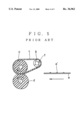
- Japanese Laid-open Patent Application No. 4-50883 discloses a fixing device as shown in FIG. 5, in which a fixing belt c with high thermal conductivity is stretched between and around a heat resisting fixing roller a having an elasticity and a heating support roller b, a pressing roller d is so arranged so to press the fixing roller a upwards through the fixing belt c, and a support member e carrying a transferred unfixed image e' is pressed by the fixing belt c and the pressing roller d for fixing image.
- This arrangement can prevent the heat resisting and elastic layer on the fixing roller a from peeling off because of the heat of a heater f.
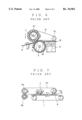
- Japanese Laid-open Patent Application No. 4-273274 discloses another apparatus as shown in FIG. 6, in which a fixing belt c 1 is stretched around a heating fixing roller a 1 and a support roller b 1 , a heating pressing roller d 1 is arranged to press the fixing belt c 1 against the heating fixing roller a 1 from the lower side thereof, an image e' on a support member e is fixed between the fixing belt c 1 and the pressing roller d 1 , the support member e is traveled by the fixing belt c 1 while cooled at a guide g by a cooling device h and, after the cooling off, the image carrying support member e is separated from the fixing belt c 1 .
- This arrangement permits fixation and separation with no offset transfer without using a release agent such as a silicone oil.
- Japanese Laid-open Patent Application No. 5-11651 discloses still another device as shown in FIG. 7, which is composed of a fixing roller a, a support roller b 2 , a fixing belt c 2 , a pressing roller d 2 and a heater f for heating the fixing belt c 2 .
- This device further has a conveyer i for conveying an unfixed image carrying support member e arranged in parallel with and underneath the fixing belt c 2 .
- a toner which forms an unfixed image e' is preliminarily heated prior to the fixation. This arrangement lowers the fixation temperature and makes the fixing device simple, compact and lower in cost.
- Japanese Laid-open Utility Model Application No. 4-124267 discloses a device in which a main body of a fixing belt consists of a thin metal member.
- the main body of the belt is smoothly risen or cooled its temperature because of its high thermal conductivity.
- a high quality of image can be achieved by the belt type fixing even in the high-speed fixation.
- the conventional device (a) nothing is disclosed as to the technical concept of heating preliminarily the unfixed image carrying support member e with use of the heated fixing belt c.
- the conventional device (c) there is disclosed the preheating by the fixing belt c 2 , however, this prior art specifically concerns to the use of thermal dissociation type capsule toner for fixing the transferred image at low-temperature. Accordingly, the device (c) teaches nothing about the prevention of an offset transfer which may be caused by the use of high-temperature fixation toner.
- the conventional device (b) primarily concerns the forced cooling of fixation belt c 1 being moved together with the image carrying support member e after fixing.
- the conventional device (d) concerns self cooling of the fixing belt through its structure while the fixing belt being traveled.
- a toner is preliminarily heated through a fixing belt prior to fixing, through which a temperature at a nip portion can be set to low.
- a high-thermal-conduction belt having a small heat capacity is used as the fixing belt, which allow the cooling of the fixing belt immediately while passing through the nip portion. Therefore, a copy sheet is separated from the fixing belt at the exit of nip portion as being lowered in the temperature of toner on the sheet and a fixed image with no offset transfer can be obtained without utilizing an oil or with the least oil on the belt.
- a fixing device for electrophotographic apparatus which comprises:
- a heating roller for supplying a heat
- an endless fixing belt consists of a metal body and a release thin film layer formed on a surface thereof, said fixing belt being stretched between the fixing roller and the heating roller, said metal body having a heat capacity per cm 2 within the range of 0.001 to 0.02 cal/°C.;
- a pressing roller for pressing said fixing roller through the fixing belt, said pressing roller forming a nip portion together with the fixing belt therebetween;
- a guide plate disposed between the heating roller and the nip portion for guiding an unfixed image carrying support member to the nip portion, said guide plate forming substantially a linear heating path together with said fixing belt therebetween.
- the main body of the metal belt is formed by nickel electroforming and has a thickness of 45 ⁇ m.
- the release thin film is made of a silicone rubber.
- a preferable range of thickness of release thin film is 10 to 200 ⁇ m. More preferably, the thickness of release thin film is in the range of 50 to 100 ⁇ m.
- a thickness of the fixing belt is preferably within the range of 0.02 to 0.2 mm. Also, the guide plate is provided with a clearance within the range of 0.5 to 10 mm relative to the fixing belt.
- the heating roller is kept at a temperature preferably in the range of 140° to 190° C., more preferably in the range of 150° to 170° C.
- the pressing roller is kept at a temperature in the range of 100° to 138° C. at the nip portion, more preferably in the range of 108° to 123° C.
- the fixing belt is kept at a temperature in the heating path preferably in the range of 135° to 185° C., more preferably in the range of 145° to 164° C.
- the fixing belt is highly thermally conductive and has a small heat capacity, so that the heat is transferred from the fixing belt to the unfixed image carrying support member at the nip portion, which cools the fixing belt. This lowers the temperature of fused toner, whereby the toner can be surely separated from the fixing belt.
- FIG. 1 is a side view to show an embodiment of the present invention
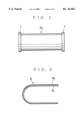
- FIG. 2 is a front view of a heating roller in the embodiment
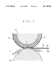
- FIG. 3 is an enlarged cross section of a fixing belt in the embodiment
- FIG. 4 is an enlarged drawing to illustrate the operation of a nip portion
- FIG. 5 is an explanatory drawing to show a conventional example
- FIG. 6 is an explanatory drawing to illustrate another conventional example.
- FIG. 7 is an explanatory drawing to illustrate still another conventional example.
- FIG. 1 shows a fixing device for color copier.
- R 1 designates a fixing roller having an elastic surface
- R 2 designates a pressing roller
- R 3 designates a heating roller
- R 4 designates a tension roller
- B designates a fixing belt
- H 1 and H 2 designate heat sources
- S 1 and S 2 designate thermistors for temperature control means
- G designates a guide plate
- P designates a heating path for unfixed image carrying support member.
- the fixing roller R 1 having the elastic surface, which has a diameter of 40 mm is so constructed that a heat resisting elastic coating layer 2 of silicone rubber is formed with a thickness of 3 mm on an aluminum core 1. Also, the pressing roller R 2 is so constructed that a heat resisting elastic coating layer 4 of silicone rubber is formed with a thickness of 50 ⁇ m on an aluminum core 3 which has a diameter 40 mm.
- the hardness of the surface of the heat resisting elastic coating layer 2 is set to the same or softer than the hardness of the heat resisting elastic coating layer 4.
- the heating roller R 3 has a Teflon (Trademark) coating layer 6 in thickness of 30 ⁇ m on an aluminum core 5 having a diameter 40 mm, which is constructed as a stepped roller having steps 7 which are higher than the thickness of the fixing belt B at the both ends thereof in the axial direction to stop deviation of fixing belt B (see FIG. 2).
- the tension roller R 4 is formed of an aluminum material having a diameter of 20 mm.
- the shape of tension roller R 4 may be arbitrarily selected from a straight cylinder, an inverted crown, and a normal crown.
- the tension roller R 4 may be arranged also to function to clean the fixing belt or to apply a small amount of oil onto the fixing belt.
- the fixing belt B is so constructed that a release thin film B 2 of silicone rubber is formed with a thickness of 50 ⁇ m on the outer surface of the endless annular metal body having the thickness of 45 ⁇ m formed by nickel electroforming process (see FIG. 3).
- the thickness of fixing belt B is determined within the range of 0.01 to 0.2 mm.
- the main heat source H 1 is provided at the inside of the heating roller R 3 .
- the auxiliary heat source H 2 is arranged at the inside of the pressing roller R 2 .
- another auxiliary heat source may be provided with necessity at the inside the fixing roller R1 having the elastic surface.
- the thermistor S 1 is provided at the outside of the heating roller R 3 in the vicinity of the fixing belt B to control the temperature of main heat source H 1 . Also, the thermistor S 2 is provided near by the pressing roller R 2 .
- the guide plate G made of a metal material is arranged underneath the fixing belt B in the proximity of the heating roller R 3 ahead of the nip portion N and approximately in parallel with the fixing belt B with a clearance in the range of 0.5 to 10 mm, thus forming a heating path P for the unfixed image carrying support member together with the fixing belt B.
- the heating path P extends almost linearly from a portion near by the heating roller R 3 to the front of the nip portion N.
- a pair of springs 8 urge the pressing roller R 2 against the fixing roller R 1 having the elastic surface through press levers 9.
- a fixing pressure is set to 66 kg at the nip portion N.
- the fixing belt B moves linearly at a linear velocity of 100 mm/s from the heating roller R 3 to the nip portion N which is formed between the surface of the elastic fixing roller R 1 and the pressing roller R 2 .
- the unfixed image carrying support member C is fed through the heating path P on the guide plate G at the same speed as that of the conveying means T.
- the support member C is heated by the fixing belt B and the guide plate G which stores thermal energy as being traveled through the heating path P formed on the guide plate G while being kept in a non-contact state with the fixing belt B.
- the heating conditions are set as follows.
- the temperature of heating roller R 3 is preferably in the range of 140° to 190° C., more preferably in the range of 150° to 170° C.
- the temperature of fixing belt B in the heating path P is preferably in the range of 135° to 185° C., more preferably in the range of 145° to 165° C.
- the temperature of pressing roller R 2 at the nip portion N is preferably in the range of 100° to 138° C., more preferably in the range of 108° to 123° C.
- the thermistor S1 controls the temperature to be within the above ranges.
- the toner which forms the unfixed image C 1 is softened while traveling through the heating path P.
- the fixing belt B Since the fixing belt B is made thin in order to make the heat capacity smaller, it can be readily heated up to a temperature necessary for fixation at the heating roller R 3 . After well heated, the fixing belt B reached to the nip portion N.
- the support member C carrying the unfixed image C 1 is traveled at the same speed as the fixing belt B through the heating path P in contact with the heat-storing guide plate G while, also, heated by a radiant heat from the fixing belt B.
- the unfixed image C 1 reaches a softened state just before fusing, prior to reaching the nip portion N.
- the preheating effect permits the unfixed image C 1 to melt at the temperature of nip portion N which is lower than that of the conventional fixing device, thus fixing the image.
- the fixing belt B Since the temperature of nip portion N is set lower than the temperature of fixing belt B, the fixing belt B itself is formed thinner to make a heat capacity small and the fixing roller R 1 having the elastic surface has a lower thermal conductivity than the fixing belt B which has a high thermal conductivity, the fixing belt B provides the unfixed image C 1 and the support member C with heat during fixation, so that the fixing belt B itself is cooled. Accordingly, the temperature of toner at the exit of nip portion N becomes far lower than that of the conventional roller fixing method. Further, the releasing becomes better between the toner which constitutes the unfixed image C 1 and the release thin film B 2 of the fixing belt B. Therefore, a fixed image having no offset transfer can be obtained without using any oil or at least using the least oil applied on the belt.
- the metal body B1 of the fixing belt B has a heat capacity per cm 2 in the range of 0.001 to 0.02 cal/°C. Below this range, the heat capacity is too small and then the temperature of heating roller R 3 must be set higher. In that case, a thermal load becomes too great on the fixing belt B. While above that range, the heat capacity becomes too large and then a temperature drop in the nip portion N becomes small. In that case, a considerable amount of oil must be applied on the belt to stop occurrence of offset transfer.
- the thickness of release thin film B 2 is in the range of 10 to 200 ⁇ m, preferably in the range of 50 to 100 ⁇ m. Over 200 ⁇ m, thermal responsibility becomes poor, which would result in failing to radiate the heat of metal body B 1 to the unfixed image C 1 and the support member C thereof sufficiently.
- the surface hardness of the surface elastic fixing roller R 1 is set to the same as or softer than that of pressing roller R 2 , so that a part of pressing roller R 2 and the fixing belt B cut into the elastic surface of the fixing roller R 1 at the nip portion N. Accordingly, when the image carrying support member C such as paper leaves the nip portion N, the leaving end thereof is below the horizontal plane and is directed downward on the pressing roller R 2 side, which can obviate a separation pawl on the fixing belt B side (see FIG. 4).
- the fixing belt B is made of a metal material, it is high in stiffness. Thus, the belt itself is little constricted or waved. Accordingly, the belt can fully stand when the deviating force occurring in the nip portion N is corrected by the step portions 7, which are provided on the heating roller R 3 and having the height greater than the thickness of belt, with use of the stiffness of fixing belt B.
- More preferable temperature conditions are as follows:
- the fixing device of the present invention is so arranged that the endless fixing belt being provided with the release thin film on the surface of the metal body is stretched between the fixing roller having the elastic surface and the heating roller, the pressing roller is arranged to be pressed against the fixing roller having the elastic surface from the lower side thereof through the fixing belt to form the nip portion between the fixing belt and the pressing roller.
- the guide plate for unfixed image carrying support member is provided underneath the fixing belt, between the heating roller and the nip portion, to form the nearly linear heating path between the guide plate and the fixing belt, and the metal body of the fixing belt has a heat capacity per cm 2 in the range of 0.001 to 0.02 cal/°C.
- the preheating effect in the heating path lowers the fixing temperature at the nip portion, and the self cooling of the fixing belt having the small-heat-capacity at the nip portion decreases the temperature of unfixed image carrying support member so as to enhance release of image from the fixing belt, whereby a fixed image with no offset can be obtained without using oil or with use of the least amount of oil on the fixing belt.
Landscapes
- Physics & Mathematics (AREA)
- General Physics & Mathematics (AREA)
- Fixing For Electrophotography (AREA)
Abstract
A fixing device to be used in electrophotographic apparatus for providing a clear fixed image with no offset with use of no oil or the least amount of oil, wherein an endless fixing belt provided with a metal body having a release thin film thereon is stretched between a fixing roller having a elastic surface and a heating roller, a pressing roller is arranged to press the surface of the elastic fixing roller upwardly from the lower side thereof through the fixing belt to form a nip portion between the fixing belt and the pressing roller, a guide plate for unfixed image carrying support member is provided underneath the fixing belt, between the heating roller and the nip portion, to form substantially a linear heating path between the guide plate and the fixing belt, and the metal body of the fixing belt has a heat capacity per cm2 within a range of 0.001 to 0.02 cal/°C.
Description
1. Field of the Invention
The present invention relates to a fixing device for electrophotographic apparatus, which is used to fix an unfixed toner image on a copy sheet by fusion with pressure.
2. Description of the Prior Art
Many conventional fixing devices for electrophotographic apparatus employ a so-called heating roller method for fixing a toner image. In this method, a heat source is provided inside a pair of rollers coated with a nonsticky material, the rollers are rotated under a suitable pressure therebetween, and a copy sheet onto which a toner image has transferred is passed through the pair of rollers for fixing the transferred toner image.
The recent technology has developed another method wherein a belt is wound around a pair of rollers and a third roller, and a transferred toner image on a copy sheet is then pressed against the surface of the belt with pressure for fixing. Examples of the prior art methods are as follows.
(a) Japanese Laid-open Patent Application No. 4-50883 discloses a fixing device as shown in FIG. 5, in which a fixing belt c with high thermal conductivity is stretched between and around a heat resisting fixing roller a having an elasticity and a heating support roller b, a pressing roller d is so arranged so to press the fixing roller a upwards through the fixing belt c, and a support member e carrying a transferred unfixed image e' is pressed by the fixing belt c and the pressing roller d for fixing image. This arrangement can prevent the heat resisting and elastic layer on the fixing roller a from peeling off because of the heat of a heater f.
(b) Japanese Laid-open Patent Application No. 4-273274 discloses another apparatus as shown in FIG. 6, in which a fixing belt c1 is stretched around a heating fixing roller a1 and a support roller b1, a heating pressing roller d1 is arranged to press the fixing belt c1 against the heating fixing roller a1 from the lower side thereof, an image e' on a support member e is fixed between the fixing belt c1 and the pressing roller d1, the support member e is traveled by the fixing belt c1 while cooled at a guide g by a cooling device h and, after the cooling off, the image carrying support member e is separated from the fixing belt c1. This arrangement permits fixation and separation with no offset transfer without using a release agent such as a silicone oil.
(c) Japanese Laid-open Patent Application No. 5-11651 discloses still another device as shown in FIG. 7, which is composed of a fixing roller a, a support roller b2, a fixing belt c2, a pressing roller d2 and a heater f for heating the fixing belt c2. This device further has a conveyer i for conveying an unfixed image carrying support member e arranged in parallel with and underneath the fixing belt c2. In this arrangement, a toner which forms an unfixed image e' is preliminarily heated prior to the fixation. This arrangement lowers the fixation temperature and makes the fixing device simple, compact and lower in cost.
(d) Japanese Laid-open Utility Model Application No. 4-124267 discloses a device in which a main body of a fixing belt consists of a thin metal member. The main body of the belt is smoothly risen or cooled its temperature because of its high thermal conductivity. Thus, a high quality of image can be achieved by the belt type fixing even in the high-speed fixation.
In the conventional device (a), nothing is disclosed as to the technical concept of heating preliminarily the unfixed image carrying support member e with use of the heated fixing belt c. In the conventional device (c), there is disclosed the preheating by the fixing belt c2, however, this prior art specifically concerns to the use of thermal dissociation type capsule toner for fixing the transferred image at low-temperature. Accordingly, the device (c) teaches nothing about the prevention of an offset transfer which may be caused by the use of high-temperature fixation toner.
Further, the conventional device (b) primarily concerns the forced cooling of fixation belt c1 being moved together with the image carrying support member e after fixing. The conventional device (d) concerns self cooling of the fixing belt through its structure while the fixing belt being traveled.
It is an object of the present invention to provide a fixing device for electrophotographic apparatus which can obtain a clear fixed image without an offset transfer.
In the present invention, a toner is preliminarily heated through a fixing belt prior to fixing, through which a temperature at a nip portion can be set to low. According to the present invention, a high-thermal-conduction belt having a small heat capacity is used as the fixing belt, which allow the cooling of the fixing belt immediately while passing through the nip portion. Therefore, a copy sheet is separated from the fixing belt at the exit of nip portion as being lowered in the temperature of toner on the sheet and a fixed image with no offset transfer can be obtained without utilizing an oil or with the least oil on the belt.
The above objective of the present invention can be achieved by a fixing device for electrophotographic apparatus which comprises:
a fixing roller having an elastic surface;
a heating roller for supplying a heat;
an endless fixing belt consists of a metal body and a release thin film layer formed on a surface thereof, said fixing belt being stretched between the fixing roller and the heating roller, said metal body having a heat capacity per cm2 within the range of 0.001 to 0.02 cal/°C.;
a pressing roller for pressing said fixing roller through the fixing belt, said pressing roller forming a nip portion together with the fixing belt therebetween; and
a guide plate disposed between the heating roller and the nip portion for guiding an unfixed image carrying support member to the nip portion, said guide plate forming substantially a linear heating path together with said fixing belt therebetween.
The main body of the metal belt is formed by nickel electroforming and has a thickness of 45 μm.
The release thin film is made of a silicone rubber. A preferable range of thickness of release thin film is 10 to 200 μm. More preferably, the thickness of release thin film is in the range of 50 to 100 μm.
A thickness of the fixing belt is preferably within the range of 0.02 to 0.2 mm. Also, the guide plate is provided with a clearance within the range of 0.5 to 10 mm relative to the fixing belt.
The heating roller is kept at a temperature preferably in the range of 140° to 190° C., more preferably in the range of 150° to 170° C. The pressing roller is kept at a temperature in the range of 100° to 138° C. at the nip portion, more preferably in the range of 108° to 123° C. The fixing belt is kept at a temperature in the heating path preferably in the range of 135° to 185° C., more preferably in the range of 145° to 164° C.
In the present invention, the fixing belt is highly thermally conductive and has a small heat capacity, so that the heat is transferred from the fixing belt to the unfixed image carrying support member at the nip portion, which cools the fixing belt. This lowers the temperature of fused toner, whereby the toner can be surely separated from the fixing belt.
Further objects and advantages of the present invention will be apparent from the following description of the preferred embodiment of the invention as illustrated in the accompanying drawings.
FIG. 1 is a side view to show an embodiment of the present invention;
FIG. 2 is a front view of a heating roller in the embodiment;
FIG. 3 is an enlarged cross section of a fixing belt in the embodiment;
FIG. 4 is an enlarged drawing to illustrate the operation of a nip portion;
FIG. 5 is an explanatory drawing to show a conventional example;
FIG. 6 is an explanatory drawing to illustrate another conventional example; and
FIG. 7 is an explanatory drawing to illustrate still another conventional example.
FIG. 1 shows a fixing device for color copier. In FIG. 1, R1 designates a fixing roller having an elastic surface, R2 designates a pressing roller, R3 designates a heating roller, R4 designates a tension roller, B designates a fixing belt, H1 and H2 designate heat sources, S1 and S2 designate thermistors for temperature control means, G designates a guide plate, and P designates a heating path for unfixed image carrying support member.
The fixing roller R1 having the elastic surface, which has a diameter of 40 mm, is so constructed that a heat resisting elastic coating layer 2 of silicone rubber is formed with a thickness of 3 mm on an aluminum core 1. Also, the pressing roller R2 is so constructed that a heat resisting elastic coating layer 4 of silicone rubber is formed with a thickness of 50 μm on an aluminum core 3 which has a diameter 40 mm. The hardness of the surface of the heat resisting elastic coating layer 2 is set to the same or softer than the hardness of the heat resisting elastic coating layer 4.
The heating roller R3 has a Teflon (Trademark) coating layer 6 in thickness of 30 μm on an aluminum core 5 having a diameter 40 mm, which is constructed as a stepped roller having steps 7 which are higher than the thickness of the fixing belt B at the both ends thereof in the axial direction to stop deviation of fixing belt B (see FIG. 2).
The tension roller R4 is formed of an aluminum material having a diameter of 20 mm. The shape of tension roller R4 may be arbitrarily selected from a straight cylinder, an inverted crown, and a normal crown. The tension roller R4 may be arranged also to function to clean the fixing belt or to apply a small amount of oil onto the fixing belt.
The fixing belt B is so constructed that a release thin film B2 of silicone rubber is formed with a thickness of 50 μm on the outer surface of the endless annular metal body having the thickness of 45 μm formed by nickel electroforming process (see FIG. 3). The thickness of fixing belt B is determined within the range of 0.01 to 0.2 mm.
The main heat source H1 is provided at the inside of the heating roller R3. The auxiliary heat source H2 is arranged at the inside of the pressing roller R2. In addition, another auxiliary heat source may be provided with necessity at the inside the fixing roller R1 having the elastic surface.
The thermistor S1 is provided at the outside of the heating roller R3 in the vicinity of the fixing belt B to control the temperature of main heat source H1. Also, the thermistor S2 is provided near by the pressing roller R2.
The guide plate G made of a metal material is arranged underneath the fixing belt B in the proximity of the heating roller R3 ahead of the nip portion N and approximately in parallel with the fixing belt B with a clearance in the range of 0.5 to 10 mm, thus forming a heating path P for the unfixed image carrying support member together with the fixing belt B. The heating path P extends almost linearly from a portion near by the heating roller R3 to the front of the nip portion N.
A pair of springs 8 urge the pressing roller R2 against the fixing roller R1 having the elastic surface through press levers 9. A fixing pressure is set to 66 kg at the nip portion N.
In operation, the fixing belt B moves linearly at a linear velocity of 100 mm/s from the heating roller R3 to the nip portion N which is formed between the surface of the elastic fixing roller R1 and the pressing roller R2. The unfixed image carrying support member C is fed through the heating path P on the guide plate G at the same speed as that of the conveying means T. The support member C is heated by the fixing belt B and the guide plate G which stores thermal energy as being traveled through the heating path P formed on the guide plate G while being kept in a non-contact state with the fixing belt B. The heating conditions are set as follows. The temperature of heating roller R3 is preferably in the range of 140° to 190° C., more preferably in the range of 150° to 170° C. The temperature of fixing belt B in the heating path P is preferably in the range of 135° to 185° C., more preferably in the range of 145° to 165° C. The temperature of pressing roller R2 at the nip portion N is preferably in the range of 100° to 138° C., more preferably in the range of 108° to 123° C. The thermistor S1 controls the temperature to be within the above ranges. The toner which forms the unfixed image C1 is softened while traveling through the heating path P.
Since the fixing belt B is made thin in order to make the heat capacity smaller, it can be readily heated up to a temperature necessary for fixation at the heating roller R3. After well heated, the fixing belt B reached to the nip portion N. The support member C carrying the unfixed image C1 is traveled at the same speed as the fixing belt B through the heating path P in contact with the heat-storing guide plate G while, also, heated by a radiant heat from the fixing belt B. Thus, the unfixed image C1 reaches a softened state just before fusing, prior to reaching the nip portion N. The preheating effect permits the unfixed image C1 to melt at the temperature of nip portion N which is lower than that of the conventional fixing device, thus fixing the image.
Since the temperature of nip portion N is set lower than the temperature of fixing belt B, the fixing belt B itself is formed thinner to make a heat capacity small and the fixing roller R1 having the elastic surface has a lower thermal conductivity than the fixing belt B which has a high thermal conductivity, the fixing belt B provides the unfixed image C1 and the support member C with heat during fixation, so that the fixing belt B itself is cooled. Accordingly, the temperature of toner at the exit of nip portion N becomes far lower than that of the conventional roller fixing method. Further, the releasing becomes better between the toner which constitutes the unfixed image C1 and the release thin film B2 of the fixing belt B. Therefore, a fixed image having no offset transfer can be obtained without using any oil or at least using the least oil applied on the belt.
The metal body B1 of the fixing belt B has a heat capacity per cm2 in the range of 0.001 to 0.02 cal/°C. Below this range, the heat capacity is too small and then the temperature of heating roller R3 must be set higher. In that case, a thermal load becomes too great on the fixing belt B. While above that range, the heat capacity becomes too large and then a temperature drop in the nip portion N becomes small. In that case, a considerable amount of oil must be applied on the belt to stop occurrence of offset transfer. The thickness of release thin film B2 is in the range of 10 to 200 μm, preferably in the range of 50 to 100 μm. Over 200 μm, thermal responsibility becomes poor, which would result in failing to radiate the heat of metal body B1 to the unfixed image C1 and the support member C thereof sufficiently.
The surface hardness of the surface elastic fixing roller R1 is set to the same as or softer than that of pressing roller R2, so that a part of pressing roller R2 and the fixing belt B cut into the elastic surface of the fixing roller R1 at the nip portion N. Accordingly, when the image carrying support member C such as paper leaves the nip portion N, the leaving end thereof is below the horizontal plane and is directed downward on the pressing roller R2 side, which can obviate a separation pawl on the fixing belt B side (see FIG. 4).
In case the pressing roller R2 is too cold when right after the start such as in a cold district, there are caused problems in fixing image. In that case, the auxiliary heat source H2 is brought into operation to heat.
Since the fixing belt B is made of a metal material, it is high in stiffness. Thus, the belt itself is little constricted or waved. Accordingly, the belt can fully stand when the deviating force occurring in the nip portion N is corrected by the step portions 7, which are provided on the heating roller R3 and having the height greater than the thickness of belt, with use of the stiffness of fixing belt B.
Experiments were implemented using the above fixing device under the conditions as follows and as listed in the following table.
______________________________________
Toner used:         toner for Minolta camera
                    CF-70
Fixed conditions:
linear speed of fixing belt
                    100 mm/s
pressing force of pressing roller
                     66 kg
clearance between fixing belt and
                     3 Mm
guide plate
Structure:          as shown in FIG. 1
______________________________________
______________________________________
                      Offset
     Heat   Press  Nip entr.
                          Nip exit         with
     roll   roll   temp. of
                          temp. of         a
     temp.  temp.  fix. belt
                          fix. belt
                                 Fix- no   little
                                                Jam-
Ex   ° C.
            ° C.
                   ° C.
                          ° C.
                                 ation
                                      oil  oil  ming
______________________________________
1    140    100    135    113    Δ
                                      ◯
                                           ◯
                                                No
2    150    108    145    118    ◯
                                      ◯
                                           ◯
                                                No
3    160    115    155    126    ◯
                                      ◯
                                           ◯
                                                No
4    170    123    165    134    ◯
                                      ◯
                                           ◯
                                                No
5    180    130    175    142    ◯
                                      Δ
                                           ◯
                                                No
6    190    138    185    150    ◯
                                      X    Δ
                                                No
______________________________________
 Guide plate temperature: 84° C. (heat roller: 140° C.) to
 115° C. (heat roller: 190° C.)
In the above table, a circle represents a good result, a cross a poor result, and a triangle an acceptable result. In Experiment 6, offset occurs in case of no release agent being used, which is not acceptable. However, by using a small amount of release agent, the occurrence of offset can be eliminated. It is seen from the above table that good or acceptable results were obtained in the other cases. Accordingly, preferable temperature conditions are as follows:
______________________________________
Heating roller:
               140 to 190° C.
Pressing roller:
               100 to 138° C. (at nip portion)
Fixing belt:   135 to 185° C. (at the entrance of
               nip portion)
______________________________________
More preferable temperature conditions are as follows:
______________________________________
Heating roller:
               150 to 170° C.
Pressing roller:
               108 to 123° C. (at nip portion)
Fixing belt:   145 to 165° C. (at the entrance of
               nip portion)
______________________________________
Another experiments were conducted by using the fixing device of the present invention as well as a conventional fixing device employing the roller fixing method. An image was fixed on an OHP sheet by the fixing device of the present invention or by the conventional fixing device. The toner used was the one for Minolta camera CF-70. The conventional fixing device was the one in the camera CF-70. The fixing results were compared between the two fixing devices by measuring the transmittance of OHP.
Results in measuring the transmittance of OHP are as follows.
Total transmittance: No difference was observed between the roller fixation and the belt fixation.
Transmittance: The belt fixation showed 2 to 3 times higher in value than those of the roller fixation for the colors.
Turbidity: The turbidity by the belt fixation was about one half of that of the roller fixation in each color.
The above results show that the belt/toner surface temperature in belt fixation is lowered at the time of discharging the sheet as compared to that of the roller fixation. Since the cohesive force of toner is stronger and that the toner is not pulled by the fixing belt, thus resulting in a smooth toner surface.
As described above, the fixing device of the present invention is so arranged that the endless fixing belt being provided with the release thin film on the surface of the metal body is stretched between the fixing roller having the elastic surface and the heating roller, the pressing roller is arranged to be pressed against the fixing roller having the elastic surface from the lower side thereof through the fixing belt to form the nip portion between the fixing belt and the pressing roller. The guide plate for unfixed image carrying support member is provided underneath the fixing belt, between the heating roller and the nip portion, to form the nearly linear heating path between the guide plate and the fixing belt, and the metal body of the fixing belt has a heat capacity per cm2 in the range of 0.001 to 0.02 cal/°C. In this arrangement, the preheating effect in the heating path lowers the fixing temperature at the nip portion, and the self cooling of the fixing belt having the small-heat-capacity at the nip portion decreases the temperature of unfixed image carrying support member so as to enhance release of image from the fixing belt, whereby a fixed image with no offset can be obtained without using oil or with use of the least amount of oil on the fixing belt.
Many modifications of the embodiments may be made without departing from the spirit and scope of the present invention. It should be understood that the present invention is not limited to the specific embodiments described in the specification.
Claims (11)
1. A fixing device for electrophotographic apparatus, comprising:
a fixing roller having an elastic surface;
a heating roller for supplying a heat;
an endless fixing belt comprising a metal body and a release thin film formed on a surface thereof, said fixing belt being stretched between the fixing roller and the heating roller, said metal body having a heat capacity per cm2 in the range of 0.001 to 0.02 cal/°C.
a pressing roller for pressing said fixing roller through the fixing belt, said pressing roller forming a nip portion together with the fixing belt therebetween; and
a guide plate disposed between the heating roller and the nip portion to guide an unfixed image carrying support member to said nip portion, said guide plate forming substantially a linear heating path together with said fixing belt.
2. A fixing device according to claim 1, wherein said metal body is formed by nickel electroforming.
3. A fixing device according to claim 1, wherein said metal body has a thickness of 45 μm.
4. A fixing device according to claim 1, wherein said release thin film is made of a silicone rubber.
5. A fixing device according to claim 1, wherein said release thin film has a thickness within a range of 10 to 200 μm.
6. A fixing device according to claim 1, wherein said release thin film has a thickness within a range of 50 to 100 μm.
7. A fixing device according to claim 1, wherein said fixing belt has a thickness within a range of 0.01 to 0.2 mm.
8. A fixing device according to claim 1, wherein said guide plate is arranged with a clearance within a range of 0.5 to 10 mm relative to the fixing belt.
9. A fixing device according to claim 1, wherein said heating roller is kept at a temperature within a range of 140° to 190° C.
10. A fixing device according to claim 1, wherein said pressing roller is kept at a temperature within a range of 100° to 138° C. at the nip portion.
11. A fixing device according to claim 1, wherein said fixing belt is kept at a temperature within a range of 135° to 185° C. in the heating path.
Priority Applications (1)
| Application Number | Priority Date | Filing Date | Title |
|---|---|---|---|
| US08/755,814 USRE36962E (en) | 1993-03-10 | 1996-11-26 | Fixing device for electrophotographic apparatus |
Applications Claiming Priority (4)
| Application Number | Priority Date | Filing Date | Title |
|---|---|---|---|
| JP5-049232 | 1993-03-10 | ||
| JP4923293 | 1993-03-10 | ||
| US08/207,466 US5465146A (en) | 1993-03-10 | 1994-03-08 | Fixing device for electrophotographic apparatus |
| US08/755,814 USRE36962E (en) | 1993-03-10 | 1996-11-26 | Fixing device for electrophotographic apparatus |
Related Parent Applications (1)
| Application Number | Title | Priority Date | Filing Date |
|---|---|---|---|
| US08/207,466 Reissue US5465146A (en) | 1993-03-10 | 1994-03-08 | Fixing device for electrophotographic apparatus |
Publications (1)
| Publication Number | Publication Date |
|---|---|
| USRE36962E true USRE36962E (en) | 2000-11-21 |
Family
ID=12825162
Family Applications (1)
| Application Number | Title | Priority Date | Filing Date |
|---|---|---|---|
| US08/755,814 Expired - Lifetime USRE36962E (en) | 1993-03-10 | 1996-11-26 | Fixing device for electrophotographic apparatus |
Country Status (2)
| Country | Link |
|---|---|
| US (1) | USRE36962E (en) |
| DE (1) | DE4407931C2 (en) |
Cited By (15)
| Publication number | Priority date | Publication date | Assignee | Title |
|---|---|---|---|---|
| US20020190060A1 (en) * | 2000-09-29 | 2002-12-19 | Masaru Imai | Image heating and image forming device |
| US6542712B2 (en) * | 2000-06-30 | 2003-04-01 | Ricoh Company, Ltd. | Method and apparatus for toner image fixing using a sheet-shaped pressing member |
| US20030147680A1 (en) * | 2000-03-15 | 2003-08-07 | Takao Kawamura | Fixing apparatus |
| US6625417B1 (en) | 1999-03-02 | 2003-09-23 | Matsushita Electric Industrial Co., Ltd. | Image heating device and image forming apparatus using the same |
| US7224922B2 (en) | 2004-02-20 | 2007-05-29 | Canon Kabushiki Kaisha | Image fixing apparatus capable of changing surface condition of fixing rotary member and fixing rotary member for use therein |
| US20090245898A1 (en) * | 2008-03-28 | 2009-10-01 | Kyocera Mita Corporation | Image forming apparatus |
| US20090245902A1 (en) * | 2008-03-28 | 2009-10-01 | Kyocera Mita Corporation | Image forming apparatus |
| US20090269109A1 (en) * | 2008-03-07 | 2009-10-29 | Kyocera Mita Corporation | Image forming apparatus |
| US20100014900A1 (en) * | 2008-07-18 | 2010-01-21 | Kyocera Mita Corporation | Image forming apparatus |
| US20100028061A1 (en) * | 2008-07-30 | 2010-02-04 | Kyocera Mita Corporation | Image forming apparatus |
| US20100046996A1 (en) * | 2008-08-25 | 2010-02-25 | Kyocera Mita Corporation | Fixing unit and image forming apparatus comprising fixing unit |
| US20100104334A1 (en) * | 2008-10-28 | 2010-04-29 | Kyocera Mita Corporation | Image forming apparatus |
| US20100272482A1 (en) * | 2009-04-24 | 2010-10-28 | Kyocera Mita Corporation | Fixing device and image forming apparatus including same |
| US20100272483A1 (en) * | 2009-04-24 | 2010-10-28 | Kyocera Mita Corporation | Fixing device and image forming apparatus including same |
| US8600280B2 (en) | 2010-03-08 | 2013-12-03 | Kyocera Document Solutions Inc. | Fixing device and image forming apparatus including the same |
Families Citing this family (6)
| Publication number | Priority date | Publication date | Assignee | Title |
|---|---|---|---|---|
| JP3482611B2 (en) * | 1997-02-14 | 2003-12-22 | 株式会社日立製作所 | Heating equipment |
| JPH1124486A (en) * | 1997-06-27 | 1999-01-29 | Nitto Kogyo Co Ltd | Fixing device |
| JP3373419B2 (en) * | 1998-01-16 | 2003-02-04 | シャープ株式会社 | Fixing method and fixing device |
| CA2259806A1 (en) * | 1998-02-09 | 1999-08-09 | Nitto Kogyo Co., Ltd. | Toner image fixing apparatus |
| JP2000305393A (en) | 1999-04-23 | 2000-11-02 | Ricoh Co Ltd | Belt fixing device and image forming device |
| DE10064557A1 (en) * | 2000-12-22 | 2002-07-11 | Nexpress Solutions Llc | Method and device for heating at least one layer of material, toner for a printing or copying device and image receiving substrate |
Citations (8)
| Publication number | Priority date | Publication date | Assignee | Title |
|---|---|---|---|---|
| JPH02158780A (en) * | 1988-12-13 | 1990-06-19 | Canon Inc | Image heating fixing device |
| JPH0450883A (en) * | 1990-06-15 | 1992-02-19 | Ricoh Co Ltd | Fuser of electrophotographic equipment |
| JPH04124267A (en) * | 1990-09-14 | 1992-04-24 | Mitsubishi Electric Corp | Ion implanting device |
| US5115279A (en) * | 1989-07-31 | 1992-05-19 | Tokyo Electric Co., Ltd. | Fixing device |
| US5149941A (en) * | 1987-06-16 | 1992-09-22 | Canon Kabushiki Kaisha | Image fixing apparatus with movable sheet member and detectors |
| JPH04273274A (en) * | 1991-02-28 | 1992-09-29 | Konica Corp | Method and device for fixing |
| US5162634A (en) * | 1988-11-15 | 1992-11-10 | Canon Kabushiki Kaisha | Image fixing apparatus |
| JPH0511651A (en) * | 1991-06-29 | 1993-01-22 | Kao Corp | Fixing device |
-
1994
- 1994-03-09 DE DE4407931A patent/DE4407931C2/en not_active Expired - Fee Related
-
1996
- 1996-11-26 US US08/755,814 patent/USRE36962E/en not_active Expired - Lifetime
Patent Citations (8)
| Publication number | Priority date | Publication date | Assignee | Title |
|---|---|---|---|---|
| US5149941A (en) * | 1987-06-16 | 1992-09-22 | Canon Kabushiki Kaisha | Image fixing apparatus with movable sheet member and detectors |
| US5162634A (en) * | 1988-11-15 | 1992-11-10 | Canon Kabushiki Kaisha | Image fixing apparatus |
| JPH02158780A (en) * | 1988-12-13 | 1990-06-19 | Canon Inc | Image heating fixing device |
| US5115279A (en) * | 1989-07-31 | 1992-05-19 | Tokyo Electric Co., Ltd. | Fixing device |
| JPH0450883A (en) * | 1990-06-15 | 1992-02-19 | Ricoh Co Ltd | Fuser of electrophotographic equipment |
| JPH04124267A (en) * | 1990-09-14 | 1992-04-24 | Mitsubishi Electric Corp | Ion implanting device |
| JPH04273274A (en) * | 1991-02-28 | 1992-09-29 | Konica Corp | Method and device for fixing |
| JPH0511651A (en) * | 1991-06-29 | 1993-01-22 | Kao Corp | Fixing device |
Cited By (28)
| Publication number | Priority date | Publication date | Assignee | Title |
|---|---|---|---|---|
| US6625417B1 (en) | 1999-03-02 | 2003-09-23 | Matsushita Electric Industrial Co., Ltd. | Image heating device and image forming apparatus using the same |
| US6678498B2 (en) | 1999-03-02 | 2004-01-13 | Matsushita Electric Industrial Co., Ltd. | Image heating device and image forming apparatus using the same |
| US6757513B2 (en) | 1999-03-02 | 2004-06-29 | Matsushita Electric Industrial Co., Ltd. | Image heating device and image forming apparatus using the same |
| US6819904B2 (en) | 1999-03-02 | 2004-11-16 | Matsushita Electric Industrial Co., Ltd. | Image heating device and image forming apparatus using the same |
| US20030147680A1 (en) * | 2000-03-15 | 2003-08-07 | Takao Kawamura | Fixing apparatus |
| US6542712B2 (en) * | 2000-06-30 | 2003-04-01 | Ricoh Company, Ltd. | Method and apparatus for toner image fixing using a sheet-shaped pressing member |
| US20020190060A1 (en) * | 2000-09-29 | 2002-12-19 | Masaru Imai | Image heating and image forming device |
| US6810230B2 (en) | 2000-09-29 | 2004-10-26 | Matsushita Electric Industrial Co., Ltd. | Electromagnetic induction image heating device and image forming apparatus |
| US7224922B2 (en) | 2004-02-20 | 2007-05-29 | Canon Kabushiki Kaisha | Image fixing apparatus capable of changing surface condition of fixing rotary member and fixing rotary member for use therein |
| US20090269109A1 (en) * | 2008-03-07 | 2009-10-29 | Kyocera Mita Corporation | Image forming apparatus |
| US7890042B2 (en) | 2008-03-07 | 2011-02-15 | Kyocera Mita Corporation | Image forming apparatus with fixing unit having induction heating member and shielding member for controlling induction heating |
| US20090245898A1 (en) * | 2008-03-28 | 2009-10-01 | Kyocera Mita Corporation | Image forming apparatus |
| US20090245902A1 (en) * | 2008-03-28 | 2009-10-01 | Kyocera Mita Corporation | Image forming apparatus |
| US7995958B2 (en) | 2008-03-28 | 2011-08-09 | Kyocera Mita Corporation | Image forming apparatus |
| US20100014900A1 (en) * | 2008-07-18 | 2010-01-21 | Kyocera Mita Corporation | Image forming apparatus |
| US8175509B2 (en) | 2008-07-18 | 2012-05-08 | Kyocera Mita Corporation | Image forming apparatus with fixing unit having magnetism adjusting capabilities |
| US20100028061A1 (en) * | 2008-07-30 | 2010-02-04 | Kyocera Mita Corporation | Image forming apparatus |
| US8606161B2 (en) | 2008-07-30 | 2013-12-10 | Kyocera Document Solutions Inc. | Image forming apparatus with induction heating type fixing unit |
| US8457539B2 (en) | 2008-07-30 | 2013-06-04 | Kyocera Mita Corporation | Image forming apparatus with induction heating type fixing unit |
| US20100046996A1 (en) * | 2008-08-25 | 2010-02-25 | Kyocera Mita Corporation | Fixing unit and image forming apparatus comprising fixing unit |
| US8346145B2 (en) | 2008-08-25 | 2013-01-01 | Kyocera Mita Corporation | Fixing unit and image forming apparatus comprising fixing unit |
| US8463170B2 (en) | 2008-10-28 | 2013-06-11 | Kyocera Mita Corporation | Image forming apparatus |
| US20100104334A1 (en) * | 2008-10-28 | 2010-04-29 | Kyocera Mita Corporation | Image forming apparatus |
| US20100272483A1 (en) * | 2009-04-24 | 2010-10-28 | Kyocera Mita Corporation | Fixing device and image forming apparatus including same |
| US8229339B2 (en) | 2009-04-24 | 2012-07-24 | Kyocera Mita Corporation | Fixing device and image forming apparatus including same |
| US8355660B2 (en) | 2009-04-24 | 2013-01-15 | Kyocera Mita Corporation | Fixing device with a shielding member having an insulated circumferential part and image forming apparatus including same |
| US20100272482A1 (en) * | 2009-04-24 | 2010-10-28 | Kyocera Mita Corporation | Fixing device and image forming apparatus including same |
| US8600280B2 (en) | 2010-03-08 | 2013-12-03 | Kyocera Document Solutions Inc. | Fixing device and image forming apparatus including the same |
Also Published As
| Publication number | Publication date |
|---|---|
| DE4407931A1 (en) | 1994-09-22 |
| DE4407931C2 (en) | 1996-02-01 |
Similar Documents
| Publication | Publication Date | Title |
|---|---|---|
| US5465146A (en) | Fixing device for electrophotographic apparatus | |
| USRE36962E (en) | Fixing device for electrophotographic apparatus | |
| JP2813297B2 (en) | Fixing device for electrophotographic device | |
| JP3042414B2 (en) | Image forming apparatus and image forming method | |
| US5614999A (en) | Fixing apparatus for reducing image distortion | |
| CA1047595A (en) | Electrophotographic fixing device | |
| CN100419591C (en) | Image heating apparatus | |
| JP4075483B2 (en) | Image forming and recording apparatus | |
| US5053829A (en) | Heat and pressure fuser with non-symmetrical nip pressure | |
| US7203453B2 (en) | Fixing device | |
| JPH10307496A (en) | Belt fixing device | |
| JPH0934291A (en) | Image fixing device | |
| JPH11242397A (en) | Device and method for fixing toner image and making it glossy | |
| JP2011123414A (en) | Fixing device | |
| JPH112987A (en) | Fixing device | |
| JP2705805B2 (en) | Fixing device | |
| JP4756619B2 (en) | Fixing device and color image forming apparatus having the fixing device | |
| JP4436405B2 (en) | Image forming and recording apparatus | |
| US5671473A (en) | Fusing device, a heating device, and a method for fusing a toner image onto a sheet | |
| JP2713698B2 (en) | Fixing device for electrophotographic device | |
| JPH0764420A (en) | Heat fixing device | |
| US3970038A (en) | Roll fuser | |
| JP2009271441A (en) | Image heating device | |
| JP3223754B2 (en) | Fixing device | |
| JPH04350883A (en) | Fixing device |
Legal Events
| Date | Code | Title | Description |
|---|---|---|---|
| FEPP | Fee payment procedure |
Free format text: PAYOR NUMBER ASSIGNED (ORIGINAL EVENT CODE: ASPN); ENTITY STATUS OF PATENT OWNER: LARGE ENTITY |
|
| FPAY | Fee payment |
Year of fee payment: 8 |
|
| FPAY | Fee payment |
Year of fee payment: 12 |
|
| AS | Assignment |
Owner name: SYNEZETEC CO., LTD., JAPAN Free format text: CHANGE OF NAME;ASSIGNOR:KAISHA, NITTO KOGYO KABUHIKI;REEL/FRAME:019725/0860 Effective date: 20070401 |