USRE28362E - Flow deflector fob nuc ear fuel element assemblies - Google Patents
Flow deflector fob nuc ear fuel element assemblies Download PDFInfo
- Publication number
- USRE28362E USRE28362E US31797772A USRE28362E US RE28362 E USRE28362 E US RE28362E US 31797772 A US31797772 A US 31797772A US RE28362 E USRE28362 E US RE28362E
- Authority
- US
- United States
- Prior art keywords
- deflector
- fuel
- cones
- grid
- fuel element
- Prior art date
- Legal status (The legal status is an assumption and is not a legal conclusion. Google has not performed a legal analysis and makes no representation as to the accuracy of the status listed.)
- Expired
Links
- 239000000446 fuel Substances 0.000 title abstract description 71
- 230000000712 assembly Effects 0.000 title description 7
- 238000000429 assembly Methods 0.000 title description 7
- 239000002826 coolant Substances 0.000 abstract description 36
- 239000003758 nuclear fuel Substances 0.000 abstract description 13
- 238000011144 upstream manufacturing Methods 0.000 abstract description 4
- 125000006850 spacer group Chemical group 0.000 description 8
- 230000004907 flux Effects 0.000 description 7
- 238000009835 boiling Methods 0.000 description 4
- 239000000463 material Substances 0.000 description 4
- 230000000694 effects Effects 0.000 description 3
- 239000007787 solid Substances 0.000 description 3
- XLYOFNOQVPJJNP-UHFFFAOYSA-N water Substances O XLYOFNOQVPJJNP-UHFFFAOYSA-N 0.000 description 3
- 239000002184 metal Substances 0.000 description 2
- 238000000034 method Methods 0.000 description 2
- 238000010521 absorption reaction Methods 0.000 description 1
- 238000007792 addition Methods 0.000 description 1
- 230000015572 biosynthetic process Effects 0.000 description 1
- 238000002485 combustion reaction Methods 0.000 description 1
- 238000010276 construction Methods 0.000 description 1
- 229910001026 inconel Inorganic materials 0.000 description 1
- 239000007788 liquid Substances 0.000 description 1
- 238000012986 modification Methods 0.000 description 1
- 230000004048 modification Effects 0.000 description 1
- 230000009290 primary effect Effects 0.000 description 1
- 230000005855 radiation Effects 0.000 description 1
- 108010071304 univin Proteins 0.000 description 1
- 238000003466 welding Methods 0.000 description 1
Images

Classifications
-
- G—PHYSICS
- G21—NUCLEAR PHYSICS; NUCLEAR ENGINEERING
- G21C—NUCLEAR REACTORS
- G21C3/00—Reactor fuel elements and their assemblies; Selection of substances for use as reactor fuel elements
- G21C3/30—Assemblies of a number of fuel elements in the form of a rigid unit
- G21C3/32—Bundles of parallel pin-, rod-, or tube-shaped fuel elements
- G21C3/322—Means to influence the coolant flow through or around the bundles
-
- Y—GENERAL TAGGING OF NEW TECHNOLOGICAL DEVELOPMENTS; GENERAL TAGGING OF CROSS-SECTIONAL TECHNOLOGIES SPANNING OVER SEVERAL SECTIONS OF THE IPC; TECHNICAL SUBJECTS COVERED BY FORMER USPC CROSS-REFERENCE ART COLLECTIONS [XRACs] AND DIGESTS
- Y02—TECHNOLOGIES OR APPLICATIONS FOR MITIGATION OR ADAPTATION AGAINST CLIMATE CHANGE
- Y02E—REDUCTION OF GREENHOUSE GAS [GHG] EMISSIONS, RELATED TO ENERGY GENERATION, TRANSMISSION OR DISTRIBUTION
- Y02E30/00—Energy generation of nuclear origin
- Y02E30/30—Nuclear fission reactors
Definitions
- a nuclear reactor fuel element assembly containing a plurality of spaced parallel fuel elements is provided with inverted conical or pyramidal deflector elements in the coolant flow channels between the fuel elements to divert the coolant flow. This disrupts the coolant layer adjacent to the fuel elements, promotes the mixing of coolant from various channels and raises the critical heat flux.
- the deflector elements are supported in position at the points of intersection of a grid structure which may also be a support grid for the fuel elements.
- the fuel or fissionable material for heterogeneous nuclear reactors is conventionally in the form of fuel elements or rods which are in turn grouped together in the reactors in bundles comprising fuel element assemblies.
- Each reactor has a number of such fuel element assemblies therein comprising the reactor core.
- the liquid moderator-coolant normally water, flows upwardly through the reactor core in the channels between the fuel elements to remove heat.
- Nuclear reactors normally have regions in the core which have a higher neutron flux and power density than other regions. This may be caused by a number of factors, one of which is the presence of control rod channels in the core. When the control rods are withdrawn, the control rod channels are filled with moderator which increases the local moderating capacity and thereby increases the power generated in the adjacent fuel. In these regions of high power density, known as hot channels," there is a higher rate of coolant enthalpy rise than in other channels. It is such hot channels that set the maximum operating conditions for the reactor and limit the amount of power that can be generated since it is in these channels that the critical thermal margin would be reached first.
- Another object of the invention is to provide flow deflectors which will effectively cause disturbance of the coolant flow adjacent the surfaces of the fuel elements as well as cause mixing of the coolant from various channels.
- a further object is to provide flow deflectors of a novel design which are supported in the core in a novel manner.
- the objects of the invention are accomplished by providing a coolant flow deflector in one or more of the spaces between adjacent fuel elements. More specifically, the deflectors are generally of a conical or pyramidal shape and are supported such that flow will be diverted from the centers of the flow channels up against or towards the adjacent fuel elements. Even more specifically, the flow deflectors are supported in the intersections of a grid which may also serve as a support grid for the fuel elements.
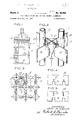
- FIG. 1 is an elevation view of a fuel assembly.
- FIG. 2 is a perspective view of a portion of a fuel element assembly illustrating the present invention.
- FIG. 3 is a section view through a fuel assembly looking downwardly towards a spacer grid.
- FIGS. 4 and 5 illustrate portions of grid-forming members.
- FIGS. 6, 7 and 8 are side, top and bottom views, respectively, of a solid deflector.
- FIGS. 9, and 11 are side, top and bottom views, respectively, of a hollow deflector.
- FIG. 12 is an exploded view illustrating the assembly technique for the deflector of FIGS. 9, 10, and 11.
- FIG. 13 is an exploded view illustrating the assembly technique for a modified deflector and a fuel element spacer ring.
- FIG. 14 is a cross-section view illustrating the deflector and spacer of FIG. 13 in relation to the fuel elements.
- FIG. 1 illustrates a fuel element assembly 10 containing individual fuel elements 12 held in place by end fittings 14 and 16 and spacer grids 18.
- the core of a nuclear reactor is formed from a plurality of such fuel assemblies and it is in such assemblies that the coolant flow deflectors of the present invention are incorporated.
- the reactor coolant which is normally water, flows up through apertures in the lower end fitting 16 and upwardly parallel with the fuel elements and out through the upper end fitting 14. It is this upward coolant flow through the fuel assemblies which is affected by the deflectors.
- the coolant flow deflectors are mounted on grid support structures located at intervals along the length of the fuel assemblies. These grids may be for the sole purpose of supporting the deflectors as shown in FIG. 2 or they may be for the additional purpose of spacing and holding the fuel elements as shown in FIG. 3.
- FIG. 2 illustrates two fuel elements 12 and a deflector 20 mounted on a grid structure 22 which is formed of members 24 and 26.
- the deflector 20 is generally pyramidal and deflects the coolant flow from the center of the flow channel between four fuel elements outwardly towards the fuel elements as indicted by the arrows. This flow deflection has two primary effects. First, the flow deflection disrupts the coolant flow conditions immediately adjacent the surface of the individual fuel elements. This tends to eliminate any DNB condition.
- FIG. 3 illustrates the invention applied to a fuel element spacer grid 18, and it is a cross-section view looking downwardly on one of such grids.
- the grid has projections 28 and springs 30 formed in each grid compartment for engaging and supporting the fuel elements 12, only one of which is illustrated.
- the illustrated spacer grid is only one of many types to which the deflectors of the present invention could be applied.
- the grid-forming straps 24 and 26 are illustrated in more detail in FIGS. 4 and 5. They are slotted at 32 and 34, respectively, and these slots fit together in egg crate fashion to form the grid.
- the cut-outs 36 are to accept the lower ends of the deflector 20 as shown in FIG. 2.
- the deflectors may be of any desired tapered shape which will be defined as conical. Although the deflectors could be for example a right cylindrical cone, the preferred conical shape is the generally pyramidal shape shown in the drawings.
- the pyramid deflector 20 shown in FIGS. 6, 7 and 8 is of solid construction with slots 38 and 40 into which the grid-forming members 4 and fit. The lower end 42 of the deflector need not come to a sharp point and is truncated.
- the deflector has slightly concave side faces as shown in FIGS. 2, 3, 7 and 8 so as to make the annular space between the deflectors 20 and the fuel elements 12 relatively constant as shown in FIG. 3. This is accomplished by having the center of the radius of curvature of the concavity correspond to the center of the adjacent fuel element.
- the deflectors are welded to the grid-forming members to hold them in position.
- FIGS. 9, and 11 illustrate a modified form of deflector 44 which is also pyramidal in shape but which is formed of sheet metal rather than being solid.
- This deflector has a slot 46 in the lower end for accepting one of the grid-forming members and another slot 48 in the upper end for accepting the other grid-forming member.
- This deflector 44 has been illustrated with flat side faces but they could also be concave as in the deflector in FIGS. 6, 7 and 8.
- FIG. 12 illustrates the configuration of the grid-forming members 50 and 52 which are used in conjunction with the deflectors 44. These grid-forming members have slots 54 and 56 for assembling the two members together and cut-outs 58 and 60 which conform to the contour of the deflector 44 and permit assembly.
- edges of the cut-outs 58 identified as 59 fit against the inside of the deflector in the pointed end while the edges 61 of the cut-outs 60 conform to the outside of the deflector adjacent the base or upper end.
- the straight edges 62 of the cut-outs permit the grid-forming members to be inserted into the deflector slots 46 and 48. The deflector is then trapped between the grid-forming members and welding or other forms of attachment need not be depended upon to keep the deflector in place.
- FIGS. 13 and 14 illustrate a further modification of the present invention in which the deflector and grid-forming members are designed so as to provide for the inclusion of a fuel element spacer and support ring 63.
- This ring fits into the enlarged cut-out portion 64 in the slots 66 in the grid-forming members 68 and 70 and act as a spring member to support the fuel elements 12 as illustrated in FIG. 14.
- the grid-forming members 68 and 70 include slots 72 and 74 for assembling them in egg crate" fashion.
- the pyramidal deflector 76 has edges 77 at the juncture between adjacent side walls. A portion 78 of each side wall at the juncture extends outwardly parallel to and spaced from the adjacent outwardly extending portion.
- the grid-forming member 70 fits down into slots 80 in the upper ends of two opposite extending portions while the grid-forming member 68 fits upwardly into the slots 82 in the lower ends of the other two extending portions 78.
- This design has the added feature that the spacer ring can be formed of a different material than that of the grid-forming members and deflectors.
- this ring 63 can be made of a material such as Inconel which will retain its spring characteristics satisfactorily during reactor operation while the grid-forming members and deflectors can be formed from a material such as Zircoloy which has a lower neutron absorption cross section and which will tend to lose some spring when subjected to radiation.
- a nuclear reactor fuel assembly comprising a plurality of longitudinally extending parallel fuel elements arranged in a spaced array forming longitudinal coolant flow channels therebetween, a plurality of deflector cones located in said flow channels between said fuel elements, said deflector cones each including an apex and a base and deflecting surfaces, said apex being located upstream and said base being located downstream with respect to the direction of said coolant flow, and means supporting said deflector cones in position] [2.
- a nuclear reactor fuel assembly as recited in claim 1 wherein said means supporting said deflector cones comprises a grid formed from a plurality of cross-laced inter engaging straps, said cones being attached to said grid at the intersections of said straps] [6.
- each of said deflector cones includes a slot in one end thereof extending from one corner to the opposite corner and a slot in the opposite end thereof extending between the other two corners and wherein a first strap extending in one direction passes through one slot and a strap extending perpendicularly to said first strap passes through the other slot whereby said deflector cone is trapped between said straps.
- a nuclear reactor fuel assembly comprising a plurality of longitudinally extending parallel fuel elements arranged in a plurality of intersecting rows and forming longitudinal coolant flow channels therebetween, a grid structure formed from a plurality of cross-laced interengaging straps, said straps interposed between adjacent rows of said fuel elements forming fuel element compartments, a plurality of generally pyramidal deflector cones located in said coolant flow channels and mounted on said grid structure at the intersection of said straps, said deflector cones having square bases located downstream with respect to the direction of coolant flow and apexes located upstream, and a plurality of fuel element support rings surrounding said deflector cones, said rings extending into said fuel element compartments so as to engage and support said fuel elements.
- a nuclear reactor fuel assembly comprising a plurality longitudinally extending parallel fuel elements arranged in spaced rows forming longitudinal coolant flow channels therebetween; a grid formed from a plurality of cross-laced interengaging straps, each of said straps being located between said spaced rows of fuel elements; and a plurality of deflector cones located in said flow channels between said fuel elements, said cones being attached to said grid at the intersections of said straps, said cones each being generally pyramidal in shape having an apex and a generally square base and four deflecting sidewall surfaces, each of said sidewall surfaces being oriented so as to face the adjacent fuel element and each sidewall surface being concave with the center of curvature of said concavity generally corresponding to the center of said adjacent fuel element whereby an intermittent annular space is formed between each fuel element and the adjacent deflector cones, the apex of said cones being located upstream and said base being located downstream with respect to the direction of said coolant flow.
Landscapes
- Physics & Mathematics (AREA)
- Engineering & Computer Science (AREA)
- Plasma & Fusion (AREA)
- General Engineering & Computer Science (AREA)
- High Energy & Nuclear Physics (AREA)
- Monitoring And Testing Of Nuclear Reactors (AREA)
Abstract
10. A NUCLEAR REACTOR FUEL ASSEMBLY COMPRISING A PLURALITY LONGITUDINALLY EXTENDING PARALLEL FUEL ELEMENTS ARRANGED IN SPACED ROWS FORMING LONGITUDINAL COOLANT FLOW CHANNELS THEREBETWEEN; A GRID FORMED FROM A PLURALITY OF CROSS-LACED INTERENGAGING STRAPS, EACH OF SAID STRAPS BEING LOCATED BETWEEN SAID SPACED ROWS OF FUEL ELEMENTS; AND A PLURALITY OF DEFLECTOR CONES LOCATED IN SAID FLOW CHANNELS BETWEEN SAID FUEL ELEMENTS, SAID CONES BEING ATTACHED TO SAID GRID AT THE INTERSECTIONS OF SAID STRAPS, SAID CONES EACH BEING GENERALLY PYRAMIDAL IN SHAPE HAVING AN APEX AND A GENERALLY SQUARE BASE AND FOUR DEFLECTING SIDEWALL SURFACES, EACH OF SAID SIDEWALL SURFACES BEING ORIENTED SO AS TO FACE THE ADJACENT FUEL ELEMENT AND EACH SIDEWALL SURFACE BEING CONCAVE WITH THE CENTER OF CURVATURE OF SAID CONCAVITY GENERALLY CORRESPONDING TO THE CENTER OF SAID ADJACENT FUEL ELEMENT WHEREBY AN INTERMITTENT ANNULAR SPACE IS FORMED BETWEEN EACH FUEL ELEMENT AND THE ADJACENT DEFLECTOR CONES, THE APEX OF SAID CONES BEING LOCATED UPSTREAM AND SAID BASE BEING LOCATED DOWNSTREAM WITH RESPECT TO THE DIRECTION OF SAID COOLANT FLOW.
Description
IE 25,362 I Liv i {iffy March J. I. uni-VIN FLOW DEFLSCTOR FOB NUC. EAR FUEL ELEMENT ASSEMBLIES Original Filed Dec. 31, 1969 2 Sheets-Sheet 1 j/l/l/f/l/ra? JW/A/ /V. CAM l///V 5y M Q/M i7 7 J/Q/VE 1 March 11, 1975 J. N. CALVIN Re. 28,362
FLOW DEFLECTOR FOR NUCJMR FUEL ELEMENT ASSEMBLIES Original Filed Dec. 31, 1969 FIGJI &J FIG.9 41
2 Sheets-Sheet 2 United States Patent Re. 28,362 Reissued Mar. 11, 1975 28,362 FLOW DEFLECTOR FOR NUCLEAR FUEL ELEMENT ASSEMBLIES John Norman Calvin, West Simsbury, Coun., assignor to Combustion Engineering, Inc., Windsor, Conn. Original No. 3,663,367, dated May 16, 1972, Ser. No. 889,548, Dec. 31, 1969. Application for reissue Dec. 26, 1972, Ser. No. 317,977
Int. Cl. GZlc 3/30 US. Cl. 176-78 4 Claims Matter enclosed in heavy brackets 1 appears in the original patent but forms no part of this reissue specification; matter printed in italics indicates the additions made by reissue.
ABSTRACT OF THE DISCLOSURE A nuclear reactor fuel element assembly containing a plurality of spaced parallel fuel elements is provided with inverted conical or pyramidal deflector elements in the coolant flow channels between the fuel elements to divert the coolant flow. This disrupts the coolant layer adjacent to the fuel elements, promotes the mixing of coolant from various channels and raises the critical heat flux. The deflector elements are supported in position at the points of intersection of a grid structure which may also be a support grid for the fuel elements.
BACKGROUND OF THE INVENTION It is well known that the fuel or fissionable material for heterogeneous nuclear reactors is conventionally in the form of fuel elements or rods which are in turn grouped together in the reactors in bundles comprising fuel element assemblies. Each reactor has a number of such fuel element assemblies therein comprising the reactor core. The liquid moderator-coolant, normally water, flows upwardly through the reactor core in the channels between the fuel elements to remove heat.
One of the operating limitations on current reactors is established by the onset of film boiling on the surfaces of the fuel elements. This phenomenon is commonly described qualitatively as departure from nucleate boiling (DNB) and quantitatively in terms of the amount of heat flux existing when DNB occurs (critical heat flux or CHF). This condition is affected by the fuel element spacing, the system pressure, the heat flux, the coolant enthalpy and the coolant velocity. When DNB occurs, there is a rapid rise in the temperature of the adjacent fuel element due to the reduced heat transfer which could result in a failure of the element. Therefore, in order to maintain a factor of safety, the reactor must be operated a certain margin below the CHF and the point at which DNB occurs. This margin is referred to as the thermal margin.
Nuclear reactors normally have regions in the core which have a higher neutron flux and power density than other regions. This may be caused by a number of factors, one of which is the presence of control rod channels in the core. When the control rods are withdrawn, the control rod channels are filled with moderator which increases the local moderating capacity and thereby increases the power generated in the adjacent fuel. In these regions of high power density, known as hot channels," there is a higher rate of coolant enthalpy rise than in other channels. It is such hot channels that set the maximum operating conditions for the reactor and limit the amount of power that can be generated since it is in these channels that the critical thermal margin would be reached first.
SUMMARY OF THE INVENTION It has been found that coolant flow inclined to the fuel elements will result in a higher value for the critical heat flux probably because such flow inhibits the formation of steam bubbles and superheated water layers which are found to exist over the fuel element surface just prior to DNB in the presence of parallel flow. It has also been found that mixing vanes or flow deflectors placed in the coolant flow channels of a reactor core will mix coolant from various channels and thus tend to reduce the effect of hot channels. The mixing lowers the high coolant enthalpy rise in the hot channels and tends to average out the enthalpy rise over the core cross section. Both effects mean that the reactor can be operated at a higher power level and still maintain a safe thermal margin.
It is therefore an object of the present invention to provide novel coolant flow deflectors in the reactor core.
Another object of the invention is to provide flow deflectors which will effectively cause disturbance of the coolant flow adjacent the surfaces of the fuel elements as well as cause mixing of the coolant from various channels.
A further object is to provide flow deflectors of a novel design which are supported in the core in a novel manner.
Briefly, the objects of the invention are accomplished by providing a coolant flow deflector in one or more of the spaces between adjacent fuel elements. More specifically, the deflectors are generally of a conical or pyramidal shape and are supported such that flow will be diverted from the centers of the flow channels up against or towards the adjacent fuel elements. Even more specifically, the flow deflectors are supported in the intersections of a grid which may also serve as a support grid for the fuel elements.
BRIEF DESCRIPTION OF THE DRAWINGS FIG. 1 is an elevation view of a fuel assembly.
FIG. 2 is a perspective view of a portion of a fuel element assembly illustrating the present invention.
FIG. 3 is a section view through a fuel assembly looking downwardly towards a spacer grid.
FIGS. 4 and 5 illustrate portions of grid-forming members.
FIGS. 6, 7 and 8 are side, top and bottom views, respectively, of a solid deflector.
FIGS. 9, and 11 are side, top and bottom views, respectively, of a hollow deflector.
FIG. 12 is an exploded view illustrating the assembly technique for the deflector of FIGS. 9, 10, and 11.
FIG. 13 is an exploded view illustrating the assembly technique for a modified deflector and a fuel element spacer ring.
FIG. 14 is a cross-section view illustrating the deflector and spacer of FIG. 13 in relation to the fuel elements.
DESCRIPTION OF THE PREFERRED EMBODIMENTS FIG. 1 illustrates a fuel element assembly 10 containing individual fuel elements 12 held in place by end fittings 14 and 16 and spacer grids 18. The core of a nuclear reactor is formed from a plurality of such fuel assemblies and it is in such assemblies that the coolant flow deflectors of the present invention are incorporated. The reactor coolant, which is normally water, flows up through apertures in the lower end fitting 16 and upwardly parallel with the fuel elements and out through the upper end fitting 14. It is this upward coolant flow through the fuel assemblies which is affected by the deflectors.
The coolant flow deflectors are mounted on grid support structures located at intervals along the length of the fuel assemblies. These grids may be for the sole purpose of supporting the deflectors as shown in FIG. 2 or they may be for the additional purpose of spacing and holding the fuel elements as shown in FIG. 3. FIG. 2 illustrates two fuel elements 12 and a deflector 20 mounted on a grid structure 22 which is formed of members 24 and 26. The deflector 20 is generally pyramidal and deflects the coolant flow from the center of the flow channel between four fuel elements outwardly towards the fuel elements as indicted by the arrows. This flow deflection has two primary effects. First, the flow deflection disrupts the coolant flow conditions immediately adjacent the surface of the individual fuel elements. This tends to eliminate any DNB condition. There is a gradual change from nucleate to stable film boiling rather than a step change. The critical heat flux is increased and it is even difficult to detect the critical point due to the gradual change in boiling characteristics. Second, the flow deflection tends to cause the coolant flowing upwardly in any particular flow channel between the fuel elements to be mixed with the coolant flow in adjacent and even more remote channels. This has the effect of evening out differences in coolant temperature between various channels.
'FIG. 3 illustrates the invention applied to a fuel element spacer grid 18, and it is a cross-section view looking downwardly on one of such grids. The grid has projections 28 and springs 30 formed in each grid compartment for engaging and supporting the fuel elements 12, only one of which is illustrated. Of course, the illustrated spacer grid is only one of many types to which the deflectors of the present invention could be applied.
The grid-forming straps 24 and 26 are illustrated in more detail in FIGS. 4 and 5. They are slotted at 32 and 34, respectively, and these slots fit together in egg crate fashion to form the grid. The cut-outs 36 are to accept the lower ends of the deflector 20 as shown in FIG. 2.
The deflectors may be of any desired tapered shape which will be defined as conical. Although the deflectors could be for example a right cylindrical cone, the preferred conical shape is the generally pyramidal shape shown in the drawings. The pyramid deflector 20 shown in FIGS. 6, 7 and 8 is of solid construction with slots 38 and 40 into which the grid-forming members 4 and fit. The lower end 42 of the deflector need not come to a sharp point and is truncated. The deflector has slightly concave side faces as shown in FIGS. 2, 3, 7 and 8 so as to make the annular space between the deflectors 20 and the fuel elements 12 relatively constant as shown in FIG. 3. This is accomplished by having the center of the radius of curvature of the concavity correspond to the center of the adjacent fuel element. The deflectors are welded to the grid-forming members to hold them in position.
FIGS. 9, and 11 illustrate a modified form of deflector 44 which is also pyramidal in shape but which is formed of sheet metal rather than being solid. This deflector has a slot 46 in the lower end for accepting one of the grid-forming members and another slot 48 in the upper end for accepting the other grid-forming member. This deflector 44 has been illustrated with flat side faces but they could also be concave as in the deflector in FIGS. 6, 7 and 8. FIG. 12 illustrates the configuration of the grid-forming members 50 and 52 which are used in conjunction with the deflectors 44. These grid-forming members have slots 54 and 56 for assembling the two members together and cut- outs 58 and 60 which conform to the contour of the deflector 44 and permit assembly. The edges of the cut-outs 58 identified as 59 fit against the inside of the deflector in the pointed end while the edges 61 of the cut-outs 60 conform to the outside of the deflector adjacent the base or upper end. The straight edges 62 of the cut-outs permit the grid-forming members to be inserted into the deflector slots 46 and 48. The deflector is then trapped between the grid-forming members and welding or other forms of attachment need not be depended upon to keep the deflector in place.
FIGS. 13 and 14 illustrate a further modification of the present invention in which the deflector and grid-forming members are designed so as to provide for the inclusion of a fuel element spacer and support ring 63. This ring fits into the enlarged cut-out portion 64 in the slots 66 in the grid-forming members 68 and 70 and act as a spring member to support the fuel elements 12 as illustrated in FIG. 14. The grid-forming members 68 and 70 include slots 72 and 74 for assembling them in egg crate" fashion. The pyramidal deflector 76 has edges 77 at the juncture between adjacent side walls. A portion 78 of each side wall at the juncture extends outwardly parallel to and spaced from the adjacent outwardly extending portion. This forms a space between the two parallel portions into which the grid-forming members fit. The grid-forming member 70 fits down into slots 80 in the upper ends of two opposite extending portions while the grid-forming member 68 fits upwardly into the slots 82 in the lower ends of the other two extending portions 78. This design has the added feature that the spacer ring can be formed of a different material than that of the grid-forming members and deflectors. This means that this ring 63 can be made of a material such as Inconel which will retain its spring characteristics satisfactorily during reactor operation while the grid-forming members and deflectors can be formed from a material such as Zircoloy which has a lower neutron absorption cross section and which will tend to lose some spring when subjected to radiation.
While several embodiments of the invention have been shown and described, it will be understood that such is merely illustrative and that changes may be made without departing from the scope of the invention as claimed.
I claim:
[1. A nuclear reactor fuel assembly comprising a plurality of longitudinally extending parallel fuel elements arranged in a spaced array forming longitudinal coolant flow channels therebetween, a plurality of deflector cones located in said flow channels between said fuel elements, said deflector cones each including an apex and a base and deflecting surfaces, said apex being located upstream and said base being located downstream with respect to the direction of said coolant flow, and means supporting said deflector cones in position] [2. A nuclear reactor fuel assembly as recited in claim 1 wherein said deflecting surfaces are oriented so as to deflect said coolant flow outwardly in said coolant channels generally towards adjacent fuel elements] [3. A nuclear reactor fuel assembly as recited in claim 1 wherein said deflector cones are each generally pyramidal in shape having a square base and four deflecting side wall surfaces, said side wall surfaces being oriented so as to face four adjacent fuel elements] [4. A nuclear reactor fuel assembly as recited in claim 3 wherein said side wall surfaces are concave and wherein the center of curvature of said concavity generally corresponds to the center of said adjacent fuel element whereby an intermittent annular space is formed between each fuel element and the adjacent deflector cones] [5. A nuclear reactor fuel assembly as recited in claim 1 wherein said means supporting said deflector cones comprises a grid formed from a plurality of cross-laced inter engaging straps, said cones being attached to said grid at the intersections of said straps] [6. A nuclear reactor fuel assembly as recited in claim 5 wherein said grid includes means for engaging and supporting said fuel elements] 7. A nuclear reactor fuel assembly as recited in claim [5] 10 wherein each of said deflector cones includes a slot in one end thereof extending from one corner to the opposite corner and a slot in the opposite end thereof extending between the other two corners and wherein a first strap extending in one direction passes through one slot and a strap extending perpendicularly to said first strap passes through the other slot whereby said deflector cone is trapped between said straps.
8. A nuclear reactor fuel assembly comprising a plurality of longitudinally extending parallel fuel elements arranged in a plurality of intersecting rows and forming longitudinal coolant flow channels therebetween, a grid structure formed from a plurality of cross-laced interengaging straps, said straps interposed between adjacent rows of said fuel elements forming fuel element compartments, a plurality of generally pyramidal deflector cones located in said coolant flow channels and mounted on said grid structure at the intersection of said straps, said deflector cones having square bases located downstream with respect to the direction of coolant flow and apexes located upstream, and a plurality of fuel element support rings surrounding said deflector cones, said rings extending into said fuel element compartments so as to engage and support said fuel elements.
9. A nuclear reactor fuel assembly as recited in claim 8 wherein said deflector cones each have four deflecting side walls each oriented so as to face an adjacent fuel element, said deflector cones each being formed from sheet metal and wherein the portions of each side wall at the juncture of said side walls extend outwardly parallel to and spaced from the adjacent outwardly extending side wall portion, said adjacent outwardly extending portions terminating and joined together in a line extending vertically from the corners of said base, slots formed in said portions where joined together, said slots being formed only partially through two opposite portions from said base end and only partially through the other two opposite portions from said apex end, said cross-laced interengaging straps containing vertical slots which are interengaged with said slots in said portions from opposite ends of said deflector cone whereby said deflector cone is held between said straps, said vertical slots further including cut-outs in which said support rings are positioned around said deflector cones.
10. A nuclear reactor fuel assembly comprising a plurality longitudinally extending parallel fuel elements arranged in spaced rows forming longitudinal coolant flow channels therebetween; a grid formed from a plurality of cross-laced interengaging straps, each of said straps being located between said spaced rows of fuel elements; and a plurality of deflector cones located in said flow channels between said fuel elements, said cones being attached to said grid at the intersections of said straps, said cones each being generally pyramidal in shape having an apex and a generally square base and four deflecting sidewall surfaces, each of said sidewall surfaces being oriented so as to face the adjacent fuel element and each sidewall surface being concave with the center of curvature of said concavity generally corresponding to the center of said adjacent fuel element whereby an intermittent annular space is formed between each fuel element and the adjacent deflector cones, the apex of said cones being located upstream and said base being located downstream with respect to the direction of said coolant flow.
References Cited The following references, cited by the Examiner, are of record in the patented file of this patent or the original patent.
UNITED STATES PATENTS 3,298,922 1/1967 Prince et al. 17678 3,301,764 1/1967 Timbs et al 17678 3,344,855 10/1967 Clark 17678 X 3,350,275 10/1967 Venier et al. 17676 X 3,356,587 12/1967 Heck 17678 3,379,618 4/1968 Frisch 17678 3,439,737 4/1969 Boorman et a1. 17678 X 3,510,397 5/1970 Zettervall l76 78 3,379,619 4/1968 Andrews et a1. 17678 3,393,128 7/1968 Obertelli et a1 l7678 LELAND A. SEBASTIAN, Primary Examiner P. K. PAVEY, Assistant Examiner
Priority Applications (1)
| Application Number | Priority Date | Filing Date | Title |
|---|---|---|---|
| US31797772 USRE28362E (en) | 1969-12-31 | 1972-12-26 | Flow deflector fob nuc ear fuel element assemblies |
Applications Claiming Priority (2)
| Application Number | Priority Date | Filing Date | Title |
|---|---|---|---|
| US88954869A | 1969-12-31 | 1969-12-31 | |
| US31797772 USRE28362E (en) | 1969-12-31 | 1972-12-26 | Flow deflector fob nuc ear fuel element assemblies |
Publications (1)
| Publication Number | Publication Date |
|---|---|
| USRE28362E true USRE28362E (en) | 1975-03-11 |
Family
ID=26981249
Family Applications (1)
| Application Number | Title | Priority Date | Filing Date |
|---|---|---|---|
| US31797772 Expired USRE28362E (en) | 1969-12-31 | 1972-12-26 | Flow deflector fob nuc ear fuel element assemblies |
Country Status (1)
| Country | Link |
|---|---|
| US (1) | USRE28362E (en) |
Cited By (6)
| Publication number | Priority date | Publication date | Assignee | Title |
|---|---|---|---|---|
| US4665866A (en) | 1985-09-04 | 1987-05-19 | Westinghouse Electric Corp. | Grid-type flow distribution baffle |
| US4818479A (en) | 1985-10-04 | 1989-04-04 | The United States Of America As Represented By The United States Department Of Energy | Nuclear reactor spacer grid and ductless core component |
| US5209897A (en) * | 1992-02-18 | 1993-05-11 | General Electric Company | BWR core assembly |
| US5327470A (en) * | 1992-02-07 | 1994-07-05 | General Electric Company | Spacer with steam separator |
| US5479390A (en) * | 1980-07-16 | 1995-12-26 | Discovision Associates | System for recording digital information in a pulse-length modulation format |
| US5493590A (en) * | 1994-03-02 | 1996-02-20 | Atomic Energy Of Canada Limited | Critical power enhancement system for a pressurized fuel channel type nuclear reactor using CHF enhancement appendages |
Citations (9)
| Publication number | Priority date | Publication date | Assignee | Title |
|---|---|---|---|---|
| US3298922A (en) * | 1963-02-22 | 1967-01-17 | Soc Anglo Belge Vulcain Sa | Nuclear fuel assembly |
| US3344855A (en) * | 1964-11-30 | 1967-10-03 | Atomic Energy Authority Uk | Heat exchange assembly including guide vane structure therein |
| US3350275A (en) * | 1965-08-26 | 1967-10-31 | Gen Electric | Reactor fuel assembly device |
| US3356587A (en) * | 1963-06-21 | 1967-12-05 | Westinghouse Electric Corp | Fuel assemblies for a neutronic reactor |
| US3379618A (en) * | 1965-12-03 | 1968-04-23 | Westinghouse Electric Corp | Fuel arrangement for a nuclear reactor |
| US3379619A (en) * | 1966-05-25 | 1968-04-23 | Westinghouse Electric Corp | Fuel assembly for nuclear reactors |
| US3393128A (en) * | 1965-08-23 | 1968-07-16 | Atomic Energy Authority Uk | Nuclear reactor fuel element assemblies |
| US3439737A (en) * | 1965-11-23 | 1969-04-22 | Atomic Energy Authority Uk | Spacer grid for heat exchange elements with mixing promotion means |
| US3510397A (en) * | 1966-08-15 | 1970-05-05 | Atomenergi Ab | Spacer for the fuel rods of the fuel element of a nuclear reactor |
-
1972
- 1972-12-26 US US31797772 patent/USRE28362E/en not_active Expired
Patent Citations (10)
| Publication number | Priority date | Publication date | Assignee | Title |
|---|---|---|---|---|
| US3298922A (en) * | 1963-02-22 | 1967-01-17 | Soc Anglo Belge Vulcain Sa | Nuclear fuel assembly |
| US3301764A (en) * | 1963-02-22 | 1967-01-31 | Soc Anglo Belge Vulcain Sa | Nuclear fuel, grid and spacer assembly |
| US3356587A (en) * | 1963-06-21 | 1967-12-05 | Westinghouse Electric Corp | Fuel assemblies for a neutronic reactor |
| US3344855A (en) * | 1964-11-30 | 1967-10-03 | Atomic Energy Authority Uk | Heat exchange assembly including guide vane structure therein |
| US3393128A (en) * | 1965-08-23 | 1968-07-16 | Atomic Energy Authority Uk | Nuclear reactor fuel element assemblies |
| US3350275A (en) * | 1965-08-26 | 1967-10-31 | Gen Electric | Reactor fuel assembly device |
| US3439737A (en) * | 1965-11-23 | 1969-04-22 | Atomic Energy Authority Uk | Spacer grid for heat exchange elements with mixing promotion means |
| US3379618A (en) * | 1965-12-03 | 1968-04-23 | Westinghouse Electric Corp | Fuel arrangement for a nuclear reactor |
| US3379619A (en) * | 1966-05-25 | 1968-04-23 | Westinghouse Electric Corp | Fuel assembly for nuclear reactors |
| US3510397A (en) * | 1966-08-15 | 1970-05-05 | Atomenergi Ab | Spacer for the fuel rods of the fuel element of a nuclear reactor |
Cited By (6)
| Publication number | Priority date | Publication date | Assignee | Title |
|---|---|---|---|---|
| US5479390A (en) * | 1980-07-16 | 1995-12-26 | Discovision Associates | System for recording digital information in a pulse-length modulation format |
| US4665866A (en) | 1985-09-04 | 1987-05-19 | Westinghouse Electric Corp. | Grid-type flow distribution baffle |
| US4818479A (en) | 1985-10-04 | 1989-04-04 | The United States Of America As Represented By The United States Department Of Energy | Nuclear reactor spacer grid and ductless core component |
| US5327470A (en) * | 1992-02-07 | 1994-07-05 | General Electric Company | Spacer with steam separator |
| US5209897A (en) * | 1992-02-18 | 1993-05-11 | General Electric Company | BWR core assembly |
| US5493590A (en) * | 1994-03-02 | 1996-02-20 | Atomic Energy Of Canada Limited | Critical power enhancement system for a pressurized fuel channel type nuclear reactor using CHF enhancement appendages |
Similar Documents
| Publication | Publication Date | Title |
|---|---|---|
| US3663367A (en) | Flow deflector for nuclear fuel element assemblies | |
| US3350275A (en) | Reactor fuel assembly device | |
| US3954560A (en) | Nuclear fuel assembly | |
| EP0260602B1 (en) | Intermediate flow mixing nonsupport grid for boiling water reactor fuel assembly | |
| US3809609A (en) | Twisted tape flow deflector in a nuclear reactor fuel assembly | |
| US3679547A (en) | Elastic support grid for nuclear fuel elements | |
| US4175004A (en) | Fuel assembly guide tube | |
| US4357298A (en) | Nuclear fuel assembly space arrangement | |
| US3787286A (en) | Fuel assembly flow redistribution | |
| US3847736A (en) | Flow twister for a nuclear reactor | |
| US3679546A (en) | Nuclear reactor fuel rod support grid | |
| US3104219A (en) | Fuel elements for nuclear reactors | |
| US4252613A (en) | Nuclear fuel assembly guide tube with integral intermittent projections | |
| US3238108A (en) | Bundle-type nuclear fuel element having novel arrangement of fissionable and fertile material | |
| US3809610A (en) | Nuclear fuel assembly with bypass coolant control | |
| CN85108227A (en) | The modular radial neutron reflector | |
| US5627865A (en) | Triangular lattice for LWR square fuel assemblies | |
| USRE28362E (en) | Flow deflector fob nuc ear fuel element assemblies | |
| US3658643A (en) | Fast-breeder nuclear reactor | |
| US3158549A (en) | Fuel assembly for neutronic reactor | |
| US3844888A (en) | Helical flow deflector cone for fuel element assemblies | |
| US3393128A (en) | Nuclear reactor fuel element assemblies | |
| US3607640A (en) | Perimeter strip for a nuclear reactor fuel assembly support grid | |
| US3795579A (en) | Nuclear fuel assembly comprising a sleeve of variable thickness | |
| KR101851181B1 (en) | Bottom nozzle including filtering device for nuclear fuel assembly |