USRE17841E - Assionob to the automatic - Google Patents
Assionob to the automatic Download PDFInfo
- Publication number
- USRE17841E USRE17841E US17841DE USRE17841E US RE17841 E USRE17841 E US RE17841E US 17841D E US17841D E US 17841DE US RE17841 E USRE17841 E US RE17841E
- Authority
- US
- United States
- Prior art keywords
- pipe
- fluid
- viscosity
- pressure
- container
- Prior art date
- Legal status (The legal status is an assumption and is not a legal conclusion. Google has not performed a legal analysis and makes no representation as to the accuracy of the status listed.)
- Expired
Links
Images
Classifications
-
- G—PHYSICS
- G01—MEASURING; TESTING
- G01N—INVESTIGATING OR ANALYSING MATERIALS BY DETERMINING THEIR CHEMICAL OR PHYSICAL PROPERTIES
- G01N11/00—Investigating flow properties of materials, e.g. viscosity, plasticity; Analysing materials by determining flow properties
- G01N11/02—Investigating flow properties of materials, e.g. viscosity, plasticity; Analysing materials by determining flow properties by measuring flow of the material
- G01N11/04—Investigating flow properties of materials, e.g. viscosity, plasticity; Analysing materials by determining flow properties by measuring flow of the material through a restricted passage, e.g. tube, aperture
- G01N11/08—Investigating flow properties of materials, e.g. viscosity, plasticity; Analysing materials by determining flow properties by measuring flow of the material through a restricted passage, e.g. tube, aperture by measuring pressure required to produce a known flow
Definitions
- This invention relates tocertain new and useful improvements i-n testing. apparatus, and more particularly to mechanism for indicating the thickness lorthinness of liquids containing matter in solution, or of solutions whose composition is free of suspended sub-V vstances or whose body consists'of heavy slow fof a.
- fluid v may moving particles such as possess great vis- *Heretoforemeters for measuring the viscosity .of fluids have been what might be termed laboratory meters, that is to say, meters which give samples ofthe material undergoing test.
- the device which I have invented is what might be termed a continuous viscosimeter, that is to say, the liquid in its process of manufacture may becontinuously run linto my machine at one end and out at the other lend during the entire run with the absolute'certainty that measurement.
- One of the objects of this invention is to provide a viscosimeter whereby the viscosity lbe directly indicated-'by an indicating device.
- l Y f Y Another object is to provide a viscosimeter of the character described whereby the vis-v cosit of the fluid may be continuously indicated.
- i y Another object of this invention is toy rovide a viscosimeter whereby'a parto the uid is passed through the tdevice so as to indicate the viscosity of the whole.
- the viscosity meter illustrated is mounted upon a board intended to be hunger otherwise suspended upon the wall, and is particu- Y disturbance as possible.
- v l Figure 1 is a vertical sectional view of my improved device complete
- Fig. 2 is a plan view thereof
- Fig. 3 4 is an end view looking from the .right side of my-device
- ISimllar reference characters indicate the parts throughput the several gures of the drawings.
- the numeral 1 indicates a container 4or beaker, preferably of steel or other suitable material, in the upper portion or antechamber 2 of which is inserted an inlet pipe 3 .in an opening -4,through whichv the liquid entersV said antechamber, whencel it descends upon the crcularbaille plate '5 attached to the lower side Vof, said antechamber ⁇ 2 bymeans of dependin vplates 5' attached thereto.
- the cover 6 o the containerA proper is provided at its center? I with an' annular opening of a sizesomewhat smaller than the baille plate 5 through which the liquid is conveyed into the .container 1, and on the left hand side is provided with an over-How. pipe (8 s'o'as to'hold the head of the material conno i stant.
- the lower portion or bottomv 9 of the container is provided with a short drain pipe 11, screw-threaded at its lower end,
- This tube 21 is of the same size atV 22 and at 23, which latter is supported a bracket bolted to the mounting board. h
- thermometric readings may be obtained when the material is' heated.
- the tube 21- is of the same size at 22 and 23, but the intermediate portion 31, 32,33, as seen in Figure 1, is considerably restricted, especially at the .throat 32.
- outlet pipe 21 is provided on its upper side with out the respetive'ends vof a pipe having outer legs 36 and -37 and inner legs 38 and 39,
- the measuring device VVor U-tube is filled with water or other liquid, preferably colored, to the center of the calibrated scalato be presently described. Due to the construction of said pipe at the throat ⁇ 32,
- a partial vacuum is formed in the outer leg or ascending tube 37, and a pressure in the outer leg or ascending tube 36 on Vthe other side, which is communicated through the goose necks at 43 and 41, respectively, tothe U-tube and the liquid therein, and the change. is noted upon the calibrated scale at 45.
- the lubricatingf qualities thereof may be compared at di erent temperatures and also the lubrieating qualities of different liquids may be compared at the same temperature.
- the gauge connection k36 serves merely to determine the reading of the gauge when noiluid flows through theV pi'pe 21.
- variable gauge reading is introduced by the lfluid pressure in the leg 37, which varies with the rate of Wv through the restriction in the Vpipe and which rate-f liow varies inversely as the viscosity of the fluid.
- the pipe portions 31, 32 and 33 arranged, as they are, in series, forxn together a com ⁇ positef restriction, with the restricted ⁇ portions 31 and 33 connected througlr'the major restriction 32.
- the leg37 of the gaugeA is tappe/dto the composite lrestriction at or near Vthe major restriction 32 serves to trans mit the pressure to the gauge; and as this 'gauge is calibrated' to' indicate a range of viscosities, it will respond to variations in the pressure due to a variation in the vis- V cosity of theiiuid.
- the container with its .by-pass provides a device for maintaining a definite pressure so as to provide means for producing a definite pressure source of fluid Whose viscosity is to be determined.
- the container 1 with its overflow 8,*therefore, provides a device.
- vthe combination with a container. adapted to contain a substance.l of undetermined viscosity, an inlet pipe in the top thereof, baffle' plates against which,
- the incoming liquid is diverted as it enters the container, and an overflow outlet nearthe top of the container 'for the discharge of the excess or fluid undergoing test,vof an outlet pipe narrowed at the throat extending laterally from the 'bottom of the container, a U- tube adjacent thereto, with ameasuring liquid therein, means connecting the U-tube with ⁇ the outlet tube, whereby a. vacuum is t produced in one leg'of the U-tube and apressure in the other legv thereof, and aA calibrated scale for registering the differences in the levels of the measuring fluid in the tive branches of the U-tube.
- a container adapted to contain a'fluid of undetermined' viscosity, an ⁇ inlet pipe, A baffle plates against which the incoming fluid is diverted'a's it enters the container, and an overflow outlet near the ⁇ .t ⁇ o ⁇ 1') ⁇ of the container for the discharge of the excess of saidfluid undergoing test, of an out-let pipe narrowed at its throat extendingflaterallv therefrom near the bottomo'f the container, a Utl-tube adjacent thereto, with a measuring liquid there- .in, means connecting the-U-tube with the outlet pipe whereby a vacuum is produced in one leg of the U-tube and a pressure in the other leg thereof, and a calibrated scale for registering the differences in the levels of the ⁇ measuring liquid in the respective branches of the U-tu A i 3.
- a viscosimgter the combination with t a container adapted to contain a fluid of undetermined viscosity, an inlet pipe, baille plates against which the incoming fluid is diverted asl it enters the container, and an overflow'outlet for the discharge of the excess of said fluid undergoing test, of an outlet pipe, a U-tube adjacent thereto .with a measuring liquid therein,l means connecting 'the .U-tube with the outlet pipe whereby a vacuum is produced in one leg of the U-tube and a pressure in the other leg thereof., and a y ⁇ the levels of the measuring liquid in the presthe outlet pipe whereby a vacuum isl produced in one leg of theU-tube, and a pressure in the other leg thereof, and a calibrated scale for registering the differences inthe levels of the measuring liquid in the respective branches of the U-tube.
- an inlet pipe vand an overflow pipe, of anoutlet pipe connected with thefcontainer and having a restricted v passing area through which the material undergoing ⁇ test is required to pass, and a pressure gauge connected to the outlet pipe near the point of restrieted area whereby the viscosity ofthe material is registered in desired units on the pressure gauge.
- the .combination 'with -a container adapted to continuously receive a fluid of undetermined viscosity, an inlet pipe adapted to continuously conduct the tiuidto said container and an overflow pipe, of an outlet pipe connected with the container and having a restricted areathrough which the material undergoing test is required to pass, and a pressuregaugeconnected to the outlet pipe near the point of restricted-area whereby the viscosity of the passing material is continuously registered in desiredunits on the pressure gauge.
- the combination with a container having an outlet and adapted toI contain a fluid of undetermined viscosity and 4 means for keeping the fluid issuing rom the outlet of said container under a delinite pressure, of an outlet pipe connected with the outlet of the container and having a restricted area through which the material- 4undergoing test is required to pass, and a pressure gauge connected tothe outlet pipe near the point of yrestricted area whereby the viscosityof the passingfmaterial is continuously registered in desired units on the pressure gauge.
- a viscosimeter means ,ior maintaining a definitepressure source of fluid whose a viscosityv is to be determined, a pipe connectnnitson the pressure gauge.
- a viscosimeter means furnishings ed with said means and having a restricted area Vthrough which the iiuid under test is required to pass, and a; pressure gauge conl i nected to thefpipe near the point of restricted area, .i w hereby Vthe viscosity of the passing material is continuously Vregistered in desired Y source of fluid whose viscosity is'to'be determined, ⁇ a pipe connected with said means and 50 under test is required to pass, means for maintaining apressure of having /arestricted area through which ililid a column height uponthe fluid the pipe, and a pressure auge connected to the pipe near the point o restricted area, whereby theviscosity ofthe passing material is continuously registered Vin desired units on* the pressure gauge.
- a viscosimeter means for maintaining a definite ⁇ ressure source of fluid whose a viscosity is to e'determined, a pipe connectedwith said source and having a restricted area through which theizidunder test is requiredto pass, a .U-tube with a measuring liquid therein, one branch of the U-tube bel certain. liquid Vazen' ing connected adjacent the restricted portion subjected to diierent pressure, and ascaleco-operating with the 'measuring liquid in the U-tube to giveV a. continuous viscosity reading. 13.
- a viscosimeter means furnishing a source of fluid whose viscosity is to be detersmined, a pipe connected with said means and having a restricted area through which the fluid under test is required to pass, means for maintaining a pressure of a certain fluid colheight upon the fluid in the pipe, a U-tube with a measuring liquidv therein, one branch of the Urtube being connected adjacent the restricted portion and the other branch at a different position in the pipe, whereby each leg of the U-tube is subjected to diiferent pressure, and a scale co-operatin gas with the measuring liquid in the U-tube to Sure gauge, one side of the gauge being con-"5 nected adjacent the restricted portion and pipe, whereby the different sides of the gauge are subjected to different pressures, and a scale co-.operating with the gauge to. give a continuous viscosity reading. 15.- In a viscosiineter, a pipe having-a restriction through whichfluid under test is rethe other side at a different
- restriction means for causing flow. ofuid undertest under a. definite head through said portions and restriction, and a pressure gauge of viscosities .calibrated to indicate a range and tapped to said restriction.
- a pipe having a restriction through which a part of the fluid under -test is required to pass means for supplying such part of the fluid from said source and to said pipe at a. definite head, and a 'pressure gauge calibrated to indicate a range of viscosit1es and connected to said pipefnear the restriction so .as to continuously respond to variations'inf source of'iluid whose viscosit is to be ei i the viscosity of the ilowing through said Y restriction.
- tinuously res pipe having a restriction through under test is required to pass, a device for maintaining a definite pressure, said device being connected -for supplyingl fluid from said source and to said pipe, and a pressure gauge calibrated to ⁇ indicate -a range of viscosities and connected to said pipe near t-he lrestriction so as to continuousl respond to variations inthe viscosity o the fiuid.
- my signature ldefinite pressure having a b pass and conf nected to sup ly fiuid to sai pipe at a defi-f nite head, an a pressure gauge calibrated to indicate a range of viscosities and connected to said pipe near the restriction so as to conity of the fluld iowing through said restric- 20.
- a container to which fluid under test is supplied 'a pipe leading from said container and means for causing ,fiuid to be supplied from l said container to said pipe under'a definite s Vso pressure, and a indicate a range of viscosities and connected to said pipe near the restriction. 21.
- a pipe having a. rstriction throughwhich fiuid under test. is required to pass means for causing flow of Huid therethrough ata definite head, a gauge calibrated to indicate a range o viscosities and'- connected to said ⁇ pipe near the re-l .variations in the viscosity of the fiuid flowond to variations in the viscoshaving a restriction,
- Pressure pressure gauge calibrated to striction so as to continuously respond to f
Landscapes
- Physics & Mathematics (AREA)
- Health & Medical Sciences (AREA)
- Life Sciences & Earth Sciences (AREA)
- Chemical & Material Sciences (AREA)
- Analytical Chemistry (AREA)
- Biochemistry (AREA)
- General Health & Medical Sciences (AREA)
- General Physics & Mathematics (AREA)
- Immunology (AREA)
- Pathology (AREA)
- Investigating Or Analysing Biological Materials (AREA)
Description
ou; 21, 1930.v
F. P. zmMERLi y VISCOSIHETER Original' Filed July 30, 1923 2 Sheets-Sheet 1 Remued oa. 21, 1930 1 uNl'rEo STATES PATENT OFFICE .-FRANZ P. ZIMMERLI, OFDETROIT, MICHIGAN, ASSIGNOR TO THE AUTOMATIC AIPLI- ANCE COMPANY, 0F ST. LOUIS, MISSOURI, A CORPORATION OF MISSOURI A vrscosmn'rnn i Original No. 1,557,517,dated October 13,- 1925, Serial No.V 654,673, :Illed July 1923. Application 01' reissue illed .Tune 10, 1929. Serial lo. 369,832.
This invention relates tocertain new and useful improvements i-n testing. apparatus, and more particularly to mechanism for indicating the thickness lorthinness of liquids containing matter in solution, or of solutions whose composition is free of suspended sub-V vstances or whose body consists'of heavy slow fof a. fluid vmay moving particles such as possess great vis- *Heretoforemeters for measuring the viscosity .of fluids have been what might be termed laboratory meters, that is to say, meters which give samples ofthe material undergoing test. The device which I have invented is what might be termed a continuous viscosimeter, that is to say, the liquid in its process of manufacture may becontinuously run linto my machine at one end and out at the other lend during the entire run with the absolute'certainty that measurement.
for viscosity isfor the entire period.
One of the objects of this invention is to provide a viscosimeter whereby the viscosity lbe directly indicated-'by an indicating device. l Y f Y Another object is to provide a viscosimeter of the character described whereby the vis-v cosit of the fluid may be continuously indicated. i y Another object of this invention is toy rovide a viscosimeter whereby'a parto the uid is passed through the tdevice so as to indicate the viscosity of the whole.
The viscosity meter illustrated is mounted upon a board intended to be hunger otherwise suspended upon the wall, and is particu- Y disturbance as possible.
Vplish this, I providea series of baille plates so .that after the container or beaker is partiall'y filled with the liquid to be measured or tested, the continuous flow or velocity `of the larly adaptable to determining the viscosity Vof oils, enamels, greases, etc., 'and'one of thev objectsv of my invention is to provide a device in which -thelintroduction of the'liquid into the mouth thereof may be made with as little In order to accominput will produce no effect upon thereading of the scale.
lmivide means for this thermometric reading of` Another object of my invention is to pro- 'same or corresponding ly understood, I -have shown in the accompanying drawin means forcarrying the same into practical effect without limiting the improvements in their useful applications to the particular'constructions, which for the purpose of explanation, have been made the su ject of illustration.
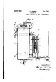
In the drawings: v l Figure 1 is a vertical sectional view of my improved device complete;
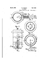
. Fig. 2is a plan view thereof;
Fig. 3 4is an end view looking from the .right side of my-device;
4 is a, sectional view on the line 4-4 of F1g..1; and,
5 is a sectional view onthe line 5--5 of` 1g. 1.
ISimllar reference characters indicate the parts throughput the several gures of the drawings.
The numeral 1 indicates a container 4or beaker, preferably of steel or other suitable material, in the upper portion or antechamber 2 of which is inserted an inlet pipe 3 .in an opening -4,through whichv the liquid entersV said antechamber, whencel it descends upon the crcularbaille plate '5 attached to the lower side Vof, said antechamber` 2 bymeans of dependin vplates 5' attached thereto. The cover 6 o the containerA proper is provided at its center? I with an' annular opening of a sizesomewhat smaller than the baille plate 5 through which the liquid is conveyed into the .container 1, and on the left hand side is provided with an over-How. pipe (8 s'o'as to'hold the head of the material conno i stant. The lower portion or bottomv 9 of the container is provided with a short drain pipe 11, screw-threaded at its lower end,
Y into which fits a correspondingly -screwthreaded block 13, upon the removal of which the remainingliquid therein is emptied so that the containermay be cleansed. As clearly seen in Figures 1 and 2, the
container is surrounded by semi-circularI m ,bands 14' bolted together onthe far side and with goose necks41, 42 and 43, the whole beembracing on its near sid'c between its ends 15 and 16, by means of bolts 17 and 18, a mounting board 19 to which the device is attache l,
Inlilling the container with `the material to be tested, it is brought into the container througli the inlet' pipe 3, any excess thereof discharging itself through the overflow 8,A
the vremainder flowing through the measuring tube 21. This tube 21 is of the same size atV 22 and at 23, which latter is supported a bracket bolted to the mounting board. h
e measuring device or Utube and connections, as seen in Fig. .2, are heldin place upon the. board by the brackets 25 and clampin bolts 26.l As seen in Figures 2, 3
'and 5, t e device is provided with a ther mometer27, by means of which thermometric readings may be obtained when the material is' heated.
The tube 21- is of the same size at 22 and 23, but the intermediate portion 31, 32,33, as seen in Figure 1, is considerably restricted, especially at the .throat 32. The
3 at such a rate that'thecontainer 1 is ed withl a slight excess overflowing through the outlet pipe 8. The remainder of the liquid Bows through the'measuringy pipe "21. The measuring device VVor U-tube is filled with water or other liquid, preferably colored, to the center of the calibrated scalato be presently described. Due to the construction of said pipe at the throat` 32,
a partial vacuum is formed in the outer leg or ascending tube 37, and a pressure in the outer leg or ascending tube 36 on Vthe other side, which is communicated through the goose necks at 43 and 41, respectively, tothe U-tube and the liquid therein, and the change. is noted upon the calibrated scale at 45. y
As thicker materials are placed in the con-` ets 34 and 35 into which are fitted tainer, thevelocity through the measuring pipe is, of course, diminished with less ac'- tion at the throat Vand less disturbance of thin, measuring tubes with various sized throats may be employed, but for continuous Work on definite material, such is'not =necessary.
Further, by providing means for ascertaining the 'heat of the liquid, the lubricatingf qualities thereof may be compared at di erent temperatures and also the lubrieating qualities of different liquids may be compared at the same temperature.
It will b e observed that since the vportion 22 is unrestricted, the pressure within the left leg 36 (Figure 1) will` remain definite and equal to. the headof the fluid in the containerA 1. Where the specific' gravity of the tluidremain's constant, the pressure will remain constant; and-with a given specilic gravity the pressure will be a definite one. The fluid pressure in the leg 37 will, however, vary .with the viscosity fithe liquid, to a value below that in the leg 36; and this siderably below atmospheric pressure, depending upon the viscosity of the fluid and, accordingly, upon the rate at which it passes through the restriction inthe pipe 21. In'
Vview ofthe fact that the fluid pressure in the'leg 36 is dein-itenot only is the liuid'flowing through. the pipe at a definite head., but as far as the gauge connection 36 is confluid pressure in the leg 37 may drop cencerned, itin'troduces no variable, due to the fact that the pipe portion 22 is unrestricted :I
accordingly, the gauge connection k36 serves merely to determine the reading of the gauge when noiluid flows through theV pi'pe 21. The
variable gauge reading is introduced by the lfluid pressure in the leg 37, which varies with the rate of Wv through the restriction in the Vpipe and which rate-f liow varies inversely as the viscosity of the fluid. v
The pipe portions 31, 32 and 33, arranged, as they are, in series, forxn together a com` positef restriction, with the restricted ` portions 31 and 33 connected througlr'the major restriction 32. The leg37 of the gaugeA is tappe/dto the composite lrestriction at or near Vthe major restriction 32 serves to trans mit the pressure to the gauge; and as this 'gauge is calibrated' to' indicate a range of viscosities, it will respond to variations in the pressure due to a variation in the vis- V cosity of theiiuid. Whilethis pressure may be below' atmosphericv pressure while fluid ows through the pipe 21, it does actually indicate a pressure with reference to O absolute.V Y v It will be noted that, sin'ce the container 1 is provided withfa by-pass 8, only apart .of the fluid is supplied to the pipe 21..while lao - to'be understood that I do not confine my-Y the remainder flows through theIby-passit is, therefore, not necessary that the whole -body of fluid pass through the pipe 2l; for
the part passed therethrough is a sample of the Whole body of fluid. Furthermore, the container with its .by-pass provides a device for maintaining a definite pressure so as to provide means for producing a definite pressure source of fluid Whose viscosity is to be determined. There is thus provided a device for continuously testing the Viscosity of af fluid flowing throughga conduit 3 while a part of the fluid from` this conduit is supplied to the pipe 21 and its restriction 32 at a definite pressure. The container 1 with its overflow 8,*therefore, provides a device.
which automatically maintains a definite pres-sure4 between the conduit and the pipe.
While I have shownand described the preferred embodiment of my invention, I wish it self to the precise details of construction herein set forth by way of illustration, as it vis'apparent that many changes and varia.-
tions may be made therein, by those skilled in the art, without departing from the spirit of the invention, or exceeding'the scope of the appended claims.
Iclaim: 1 r t 1. In a viscosimeter, vthe combination with a container. adapted to contain a substance.l of undetermined viscosity, an inlet pipe in the top thereof, baffle' plates against which,
the incoming liquid is diverted as it enters the container, and an overflow outlet nearthe top of the container 'for the discharge of the excess or fluid undergoing test,vof an outlet pipe narrowed at the throat extending laterally from the 'bottom of the container, a U- tube adjacent thereto, with ameasuring liquid therein, means connecting the U-tube with `the outlet tube, whereby a. vacuum is t produced in one leg'of the U-tube and apressure in the other legv thereof, and aA calibrated scale for registering the differences in the levels of the measuring fluid in the tive branches of the U-tube. y
2. In a vi'scosimeter, the combination with l a container adapted to contain a'fluid of undetermined' viscosity, an` inlet pipe, A baffle plates against which the incoming fluid is diverted'a's it enters the container, and an overflow outlet near the`.t`o`1')` of the container for the discharge of the excess of saidfluid undergoing test, of an out-let pipe narrowed at its throat extendingflaterallv therefrom near the bottomo'f the container, a Utl-tube adjacent thereto, with a measuring liquid there- .in, means connecting the-U-tube with the outlet pipe whereby a vacuum is produced in one leg of the U-tube and a pressure in the other leg thereof, and a calibrated scale for registering the differences in the levels of the` measuring liquid in the respective branches of the U-tu A i 3. -In a viscosimgter, the combination with t a container adapted to contain a fluid of undetermined viscosity, an inlet pipe, baille plates against which the incoming fluid is diverted asl it enters the container, and an overflow'outlet for the discharge of the excess of said fluid undergoing test, of an outlet pipe, a U-tube adjacent thereto .with a measuring liquid therein,l means connecting 'the .U-tube with the outlet pipe whereby a vacuum is produced in one leg of the U-tube and a pressure in the other leg thereof., and a y `the levels of the measuring liquid in the presthe outlet pipe whereby a vacuum isl produced in one leg of theU-tube, and a pressure in the other leg thereof, and a calibrated scale for registering the differences inthe levels of the measuring liquid in the respective branches of the U-tube.
5. In a viscosimeter, the combination with a container adapted to'contain a'fluid of undetermined viscosity, an inlet pipe, baHle plates against which the incoming fluid is diverted'as it enters the container, and an overflow o'utlet for the discharge of the excess o'f said fluid undergoing test, of an outlet pipe narrowed at itsthroat, a U-tubeadjaqent .thereto with a measuring' liquid therein,
means connecting each member of the U\tube with 'thefoutlet-pipe, whereby a. vacuum is n produced in'one leg. of the U-tubeand-afpressure in the other legthereof, and a scalefor registering the differences in the measuring liquid in the respective branches 4of the U- 6.- In aviscosimeter, the combination with a container adapted to vcontain a fluid of undetermined viscosity, an inlet pipe` baille plates againstr which "the incoming fluid is diverted as it enters the container, an' overflow outlet for the discharge of any excess of said fluid undergoing test, and a thermometer to measure the temperature of said fluid, of anv outlet pipe narrowed at the throat,y a U-tube adjacent thereto witha measuring liquid therein, means connecting each member of the U-tube with the outlet pipe whereby a vacuum is'produced in one leg of the U-tube and a pressurel in the other leg thereof, and7 a scale for registering the differences in the measuring liquid in the respective branches o f the U-tube.
7. In a v1scos1meter, the combination with determinedV viscosity, an inlet pipe vand an overflow pipe, of anoutlet pipe connected with thefcontainer and having a restricted v passing area through which the material undergoing` test is required to pass, and a pressure gauge connected to the outlet pipe near the point of restrieted area whereby the viscosity ofthe material is registered in desired units on the pressure gauge.
8. In a viscosimeter, the .combination 'with -a container adapted to continuously receive a fluid of undetermined viscosity, an inlet pipe adapted to continuously conduct the tiuidto said container and an overflow pipe, of an outlet pipe connected with the container and having a restricted areathrough which the material undergoing test is required to pass, anda pressuregaugeconnected to the outlet pipe near the point of restricted-area whereby the viscosity of the passing material is continuously registered in desiredunits on the pressure gauge.
9. In a viscosimeter, the combination with a container having an outlet and adapted toI contain a fluid of undetermined viscosity and 4 means for keeping the fluid issuing rom the outlet of said container under a delinite pressure, of an outlet pipe connected with the outlet of the container and having a restricted area through which the material- 4undergoing test is required to pass, and a pressure gauge connected tothe outlet pipe near the point of yrestricted area whereby the viscosityof the passingfmaterial is continuously registered in desired units on the pressure gauge.
'10. In a viscosimeter, means ,ior maintaining a definitepressure source of fluid whose a viscosityv is to be determined, a pipe connectnnitson the pressure gauge. l l
11. In a viscosimeter, means furnishings ed with said means and having a restricted area Vthrough which the iiuid under test is required to pass, and a; pressure gauge conl i nected to thefpipe near the point of restricted area, .i w hereby Vthe viscosity of the passing material is continuously Vregistered in desired Y source of fluid whose viscosity is'to'be determined,`a pipe connected with said means and 50 under test is required to pass, means for maintaining apressure of having /arestricted area through which ililid a column height uponthe fluid the pipe, and a pressure auge connected to the pipe near the point o restricted area, whereby theviscosity ofthe passing material is continuously registered Vin desired units on* the pressure gauge. y
12. In a viscosimeter, means for maintaining a definite` ressure source of fluid whose a viscosity is to e'determined, a pipe connectedwith said source and having a restricted area through which the luidunder test is requiredto pass, a .U-tube with a measuring liquid therein, one branch of the U-tube bel certain. liquid Vazen' ing connected adjacent the restricted portion subjected to diierent pressure, and ascaleco-operating with the 'measuring liquid in the U-tube to giveV a. continuous viscosity reading. 13. In a viscosimeter, means furnishing a source of fluid whose viscosity is to be detersmined, a pipe connected with said means and having a restricted area through which the fluid under test is required to pass, means for maintaining a pressure of a certain fluid colheight upon the fluid in the pipe, a U-tube with a measuring liquidv therein, one branch of the Urtube being connected adjacent the restricted portion and the other branch at a different position in the pipe, whereby each leg of the U-tube is subjected to diiferent pressure, and a scale co-operatin gas with the measuring liquid in the U-tube to Sure gauge, one side of the gauge being con-"5 nected adjacent the restricted portion and pipe, whereby the different sides of the gauge are subjected to different pressures, and a scale co-.operating with the gauge to. give a continuous viscosity reading. 15.- In a viscosiineter, a pipe having-a restriction through whichfluid under test is rethe other side at a different position in the,
quired to pass, means for causing flow offiluid V therethrough at a definite head, anda pres,-
sure gauge calibrated to indicate a range of viscosities and connected to said pipe near the restriction so as to continuously respond to variationsin the viscosity of the fluid flowing through said restriction. v
"16. In 'a viscosimeter, a pipe having portions arranged in series and joined b' n.
restriction, means for causing flow. ofuid undertest under a. definite head through said portions and restriction, and a pressure gauge of viscosities .calibrated to indicate a range and tapped to said restriction. Y
17. In a'viscosimeter, means furni .a
termined, a pipe having a restriction through which a part of the fluid under -test is required to pass, means for supplying such part of the fluid from said source and to said pipe at a. definite head, and a 'pressure gauge calibrated to indicate a range of viscosit1es and connected to said pipefnear the restriction so .as to continuously respond to variations'inf source of'iluid whose viscosit is to be ei i the viscosity of the ilowing through said Y restriction. y
18. In a viscosimeter, means av source of fluid whose viscosity is to .be de- Jao . quired to pass,
tinuously res pipe having a restriction through under test is required to pass, a device for maintaining a definite pressure, said device being connected -for supplyingl fluid from said source and to said pipe, and a pressure gauge calibrated to `indicate -a range of viscosities and connected to said pipe near t-he lrestriction so as to continuousl respond to variations inthe viscosity o the fiuid.
19. In a viscosimeter, striction through which termined, a which I fiuid a pipe having a reuid under testis real devlce for malntalnmg a which the uuid aows, a pipe having a' marie tion through which fluid under test 1s required to pass, a device between said conduit `and said pipe and adapted to maintain a definite pressure on the fiuid in said pipe, vand an indicating pressure gauge connected to said pipe near the restriction adapted to continuously respond to variations in the viscosity of the fiuid.
In testimony whereof I aiiix this 4th 'day of December, 1928;
FRANZ P. ZIMMERLI.
my signature ldefinite pressure having a b pass and conf nected to sup ly fiuid to sai pipe at a defi-f nite head, an a pressure gauge calibrated to indicate a range of viscosities and connected to said pipe near the restriction so as to conity of the fluld iowing through said restric- 20. In a viscosimeter, a container to which fluid under test is supplied, 'a pipe leading from said container and means for causing ,fiuid to be supplied from l said container to said pipe under'a definite s Vso pressure, and a indicate a range of viscosities and connected to said pipe near the restriction. 21. In a viscosimeter, a pipe having a. rstriction throughwhich fiuid under test. is required to pass, means for causing flow of Huid therethrough ata definite head, a gauge calibrated to indicate a range o viscosities and'- connected to said` pipe near the re-l .variations in the viscosity of the fiuid flowond to variations in the viscoshaving a restriction,
Pressure pressure gauge calibrated to striction so as to continuously respond to f,
ing .through said r'estriction, 'and means for 'a indicating the temfperature of the fiuid.
22. In a device or continuously testing the viscosityof a fiowing fiuid, a conduit through which ,the fiuid Hows,-
a pipe having a restriction through which Huid under test is required to. pass, means for supplying the fiuid from sald conduitto said pipe at a definite pressure,
' and an indicating pressuregauge connected to said pipe near the restriction adapted to eonvariations in the viscosity of the Huid iiowtesting the to variations in the vistesting the ing through said restriction.
24. In a device forcontinuousl viscosity of a flowing uid, aconl uit through flowing through said re uit through uit to'said pipe at a'definite los l lis lao
Publications (1)
| Publication Number | Publication Date |
|---|---|
| USRE17841E true USRE17841E (en) | 1930-10-21 |
Family
ID=2080643
Family Applications (1)
| Application Number | Title | Priority Date | Filing Date |
|---|---|---|---|
| US17841D Expired USRE17841E (en) | Assionob to the automatic |
Country Status (1)
| Country | Link |
|---|---|
| US (1) | USRE17841E (en) |
Cited By (1)
| Publication number | Priority date | Publication date | Assignee | Title |
|---|---|---|---|---|
| US4603979A (en) | 1983-02-07 | 1986-08-05 | Aarre Matilainen | Procedure and means for measuring the internal friction of liquid substances |
-
0
- US US17841D patent/USRE17841E/en not_active Expired
Cited By (1)
| Publication number | Priority date | Publication date | Assignee | Title |
|---|---|---|---|---|
| US4603979A (en) | 1983-02-07 | 1986-08-05 | Aarre Matilainen | Procedure and means for measuring the internal friction of liquid substances |
Similar Documents
| Publication | Publication Date | Title |
|---|---|---|
| US3435665A (en) | Capillary viscometer | |
| US2449067A (en) | Constant flow gas analyzer | |
| US2279254A (en) | Fluid density measurement | |
| US2696734A (en) | Viscometer for semifluid substances | |
| US1761295A (en) | Fluid meter | |
| USRE17841E (en) | Assionob to the automatic | |
| US2800019A (en) | Density compensating flowmeter | |
| US2671343A (en) | Vapor pressure by thermal conductivity | |
| US1863090A (en) | Method and means for measuring the viscosity of lubricating oils and other liquids | |
| US1605171A (en) | Method and apparatus for measuring the specific gravity of liquid and solid mixtures | |
| US3528282A (en) | Well tester | |
| GB711851A (en) | Improvements in and relating to apparatus for measuring viscosity of fluids | |
| US1945822A (en) | Method and apparatus for measuring viscosity | |
| US1557517A (en) | Viscosimeter | |
| US2939314A (en) | Fluid leakage meter | |
| US3033040A (en) | Density measuring apparatus | |
| US1983231A (en) | Fluid meter | |
| US2348733A (en) | Method and means for indicating the specific gravity of flowing fluids | |
| US1434198A (en) | Meter-testing machine | |
| US1759873A (en) | Apparatus for measuring the liquid contents of vessels | |
| US1674481A (en) | Flow meter | |
| US1506617A (en) | Method of and apparatus for testing gas mixtures | |
| US3473401A (en) | Device for measuring paper stock consistency | |
| US1727836A (en) | Viscometer | |
| US1660503A (en) | Fluid meter |