USRE17543E - Steering attachment fob tractors - Google Patents
Steering attachment fob tractors Download PDFInfo
- Publication number
- USRE17543E USRE17543E US17543DE USRE17543E US RE17543 E USRE17543 E US RE17543E US 17543D E US17543D E US 17543DE US RE17543 E USRE17543 E US RE17543E
- Authority
- US
- United States
- Prior art keywords
- bar
- steering
- shoe
- tractor
- carrier
- Prior art date
- Legal status (The legal status is an assumption and is not a legal conclusion. Google has not performed a legal analysis and makes no representation as to the accuracy of the status listed.)
- Expired
Links
- 238000010276 construction Methods 0.000 description 6
- 241000209149 Zea Species 0.000 description 2
- 235000005824 Zea mays ssp. parviglumis Nutrition 0.000 description 2
- 235000002017 Zea mays subsp mays Nutrition 0.000 description 2
- 235000005822 corn Nutrition 0.000 description 2
- 230000003028 elevating effect Effects 0.000 description 2
Images
Classifications
-
- A—HUMAN NECESSITIES
- A01—AGRICULTURE; FORESTRY; ANIMAL HUSBANDRY; HUNTING; TRAPPING; FISHING
- A01B—SOIL WORKING IN AGRICULTURE OR FORESTRY; PARTS, DETAILS, OR ACCESSORIES OF AGRICULTURAL MACHINES OR IMPLEMENTS, IN GENERAL
- A01B69/00—Steering of agricultural machines or implements; Guiding agricultural machines or implements on a desired track
- A01B69/007—Steering or guiding of agricultural vehicles, e.g. steering of the tractor to keep the plough in the furrow
- A01B69/008—Steering or guiding of agricultural vehicles, e.g. steering of the tractor to keep the plough in the furrow automatic
Definitions
- This invention relates to a steering attach'- ment for tractors, of the class adapted to accomplish steenring-atractorwhen plowing.
- One of the objects of the invention is to provide a shoe for the attachment at the front 0f the tractor which will be automatically maintained parallelwith the line of traction so that the supportingdoar for the guide will be maintained approxlmately at right-angles to the furrow.
- Another object is to provide a steering attachment of such construction that the tractor may travel at selected distances from the furrow,.the distance of the shoe from the furrow not being changed.
- Still another object is to provide astandard for the steering attachment for use when supportingy the guldes when turning about at the end of ⁇ a iield or when moving the guides to the right or left side of the line-of traction.
- Still another object is to provide an attachment of the class described which will resist side stresses directed thereto while cultivating ground which is inclined transversely to,
- the invention includes a steeringl attachment adapted to be used for listing and gen eral cultivation of the ground'as well as for plowing.
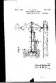
- Fig.- 1 is a plan view partly broken away,l
- Fig.' 2 is a view of the attachment in side elevation, a part of a tractor, in section, being shown.
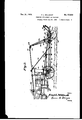
- Fig. 4 is a side view of the parts shown in Fig. 3.
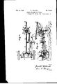
- FIG. 5 is a sectional View on line 5-5 of Fig. 1.
- ig. 6 is a sectional view on line 6-6 of Fig. 1.
- Fig. 8 is a sectional view o n line 8-8 of Fig. 1.
- Fig. 9 is a plan View of a chain-holder for the standard of the steering'attachment.
- theinvention is shown and described in connection with the front wheels 10, axle 11, the spindle-bars 12 and the couplin -rod 13 which connects the two spindlears one with the other, these being, well known parts hereinafter calledthe steering mechanism of the tractor.
- Numeral 14 indicates a steering-arm which extends forwardly of the tractor for use with other parts to be described. It may have any suitable connection with the steering mecha- 7 is a sectionalvview on line 7?-7 of "nism of the tractor, the connection shown herein being a bolt 15 (Fig: 1) ⁇ which pivotally connects the rear endof said arm 14 with the coupling-rod 13.
- I provide a carrier-beam 16 which extends forwardly from the tractor. It may have any suitable mounting of its rear end on the tractor which will permit it to have swinging movements in horizontal and vertical planes, the mounting shown herein to permit it to move vertically being a vertical pivot or bolt 17 (Figs. 1, 5) 4which is disposed in a vertical socket 18, said socket being secured to a supporting-plate 19. Brackets are secured to the front part of the axle 11 by means of a pair of U-bolts 21.
- the plate 19 is of angular form and, as clearly shown in Fig. 1, is provided with end-portions which are bent at right-angles to the body of said plate, and-by means of horizontal bolts Q2 these end-portions of said plate 19 are pivotally maintained on the brackets 20.
- the tractor may be automatically steered by means to be described necessary that the carrier-beam should ⁇ have" ⁇ "' such a mounting that it may have both vertical and horizontal movements, and the mounting as described permits these movements.
- the carrier-beam is adapted to be supported and held at a suitable distance above the ground by a flexible member or chain 23, the
- said pivotal mounting for the shoe being between the inner ends of said members 27 and 28,' and when the shoe is manufactured said members 27 and 28 may be constructed integral therewith if desired, but if produced separately said members 27 and 28 are secured rigidly with the shoe and have no movements independently of the shoe.
- Numeral 30 indicates, an equalizing-bar and, as best shown in Figs. 1 and 5 of the drawings its rear end is pivotally mounted by means of a pin 31 upon an extension of the supporting-plate 19 and therefore this bar 30 may have both vertical and horizontal movements, the centers of their arcs of movement being the pivotal mountings of their respective rear ends.
- the distance between the pivots 17 and 31 is approximately equal to the length ofthe horizontal arm ⁇ 27, and therefore when the carrier-beam is swung either to the right or left of the line of traction said members 16 and 30 will remain parallel with each other. Also it will be noted that during the horizontal movements of these bars they ⁇ may move toward each other or the reverse.
- Numeral 32 indicates a supporting-bar which is hingeably mounted ⁇ on the shoe as indicated at 33, and upon the outer end of the bar 32 is 'ournalled a pair of discs 34, these two discs eing identified as a guide-member adapted to travel in a furrow 35.
- the bar 32 is ivoted to the hinge 33 ⁇ as indicated at x.
- y umeral 36 indicates a brace or flexible member or chain which is secured at its outer end to the bar 32, its inner end being mounted on a hook 37, and it will be understood that the chain 36' may be adjusted longitudinally.
- lfhiismember 36 is for the purpose of resist- ⁇ mggstresses directed to the guide-member 34 during operation while the tractor is moving forwardly so that the bar 32 will be disposed approximately at right-angles to the shoe 26. WhileI have shown and described a chain 26 for the uses mentioned it is obvious that a metallic bar or rod could be substituted therefor and operation would be practically the same.
- the guide-member 34 While the tractor is moving forwardly the guide-member 34 will normally remain in ⁇ the furrow.
- the supporting-bar 32 will normally be disposed at right-anglesto the furrow.
- the arm 27 of the shoe is pivotally mounted, as indicated at ⁇ 39 upon the front end of the equalizing-bar 30 which4 operates as a fulcrum, and any horizontal swinging movement of the shoe will be coincidently communicated to tne steering-arm 13 and to the steering mechanism of the tractor.
- the carrier-beam 16 and equalizing-bar 30 may be disposed in angular rotation to the line ⁇ of traction, but accordingr to the present construction, the shoe will at all times be maintained parallel with the line of traction, and this feature is of great advantage since the supporting-bar 32 during operation, will be disposed approximately at right-angles to the furrow 35 so that there will be no tendency for the guide-member to leave the furrow while the tractor is moving.
- the control-bar 38 operates to advantage for many purposes as will be seen. When operating in rough ground, either plowing or listing, this bar tends to resist side stresses directed to the shoe, the equalizing-bar and enga carrier-beam, for the reason that it is mounted on the steering arm, and since the latter is pivotally mounted between its ends as indicatedV at 40, stresses directed to either side of these parts will be resisted.
- the tractor In operation, it is often desirable to have the tractor move very close to the furrow 35 especially if the ground to be plowed or listed is inclined transversely to the line of traction, and the invention includes such a mounting of the steering-arm that this may be accomplished.
- Fig. 1 of the drawings it will be seen that the carrier-beam 16, equalizing-bar 30 and steering-arm 14 are disposed approximately parallel with the line of traction and that the control-bar 38 is provided with notches 41.
- the steeringarm, at its end, ⁇ is provided with a downwardly projecting pin 42 adapted to engage in any selected notch 41, and to accomplish this adjustment, a pull-rope 43 is provided.
- the bar 38 may be swung rearwardly against the force of a spring 44 so that the pin or projection 42 may e in any selected notch of said bar 38.
- the tractor shall move with its off wheel close to the furrow the pin 42 is disposed in a notch nearer to the free end of the bar 38, the result being that the steering mechanism of the trac'- tor will be changed to cause the tractor, during its movements, to be disposed closely adjacent to the furrow 35, and during the forward travel of the tractor the carrier-beam 16 and equalizing-bar 30 will remain parallel with reference to each other but they will swing and will be inclined toward the near side of the line of traction, that is to say, the tractor and rear ends of members 16 and 30 will be disposed closer to the furrow than before and the front ends of said members 16 and 30 will be dis osed the same distance from the furrow as Eefore.
- This standard may be of any suitable construction and may have any suitable height, and as best shown in Fig. 2 of the drawings it, preferably, has a rearward inclination so that it will not be obtrusive when the supporting-bar 32 and its discs 34 have been swung upwardly.
- an inclined head-piece or plate 46 provided with a V-shaped notch 47, and upon the plate 46 is mounted a pair of rollers or pulleys 48.
- a chain 49 which is secured at one of its ends to the supporting-bar, the opposite end of said'chain being provided, preferably, with a rope or cable 50, and an operator, by use of the rope, may cause the supportingbar and discs to swing upwardly, the chain movingv between the pulleys 48, and one of the links of the chain being caught in the V-shaped notch 47, which operates to maintain the supporting-bar 32 and discs in the elevated position mentioned.
- the present invention includes such a mounting for the supporting-bar 32 and guide-member 34 that said bar may be swung in a circles arc of 180 degrees for operation at either side of the line of traction the requirement of the standard 45 or an equivalent support for a chain 49 is obvious for successful, convenient operation; According to the present construction, an operator, at a remote distance from and rearwardly of the attachment, by use of the rope 50, may cause the supporting-bar 32 to swing a complete half-circle, and since the standard has an upward and rearward inclination said bar and discs 34 will not move into enggementtherewith during their swinging movements. y
- a lister (not shownl may be attached to the tractor, rearwardly thereof, and used for cultivating the ground generally or may be used for listing two or more rows vof corn, the operation ⁇ being that fur-y rows Will be formed between the rows of corn, and the furrow 55 may be considered as a furrow formed by a lister; and it should be stated that all of the parts heretofore described for steering the tractor, are depended upon during the operation of listing as well as for plowing.
- shoe being adapted to have swingingmovef ments upwardly and downwardly on its pivotal mounting 56, a cable or rope 57 being sef cured to a ring' at the front end of the shoe so that an operator on the ltractor may control the swinging movements mentioned.
- means should be provided for maintaining the shoe in its uppermost position when swung upwardly.
- I provide a second cable or rope 58 which extends through the ring 59 and is secured at its end to a U-shaped latch 60 which is pivotally mounted on the shoe, and when the shoe is swung downwardly for engagement of its disc in the furrow, the latch is adapted to become caught upon a projection 61 which is mounted on the'yoke and which operates as a catch, a spring 62 being employed and having a connection with the shoe and said latch 60 and which normally presses said latch toward its engaging position with said projection 61.
- the guide-member 54 may be lifted from the furrow by use of the pull-ropes, the latch 60 moving from itsk locked position with the projection or catch 61 against the force of the spring 62, and the parts are of such proportions that when the shoe and discs have moved to their uppermost position the latch 60 will become caught on the bolt 29, and the parts will remain in this last named position.
- a carrier-beam provided with a shoe and mounted on the tractor to permit vertical and horizontal movements
- a brace-member connected with the supportingbar and mounted on the shoe
- a guide member rotatably mounted on the supporting-bar and adapted to travel in a furrow and to move the carrier-beam
- a steering-arm connected with the steering mechanism of the tractor
- a control-bar movable with the carrierbeam detachably connected with said steering-arm for actuating said steering-arm and ,steering mechanism of said tractor.
- a carrier-beam extending forwardly from and pivotally mounted on the tractor,an equalizing-bar disposed at the side of the carrierbeam and movable therewith, a shoe pivotally mounted on the carrier-beam and fulcrumed 'on the equalizing-bar, a supporting-bar mounted on ,the shoe.
- a guide-member rotatably mounted on the supporting-bar and adapted to travel in a furrow and to move the supporting-bar, saidshoe and carrier-beam, a steering-arm connected with the steering mechanism of the tractor, and a control-bar movable with the carrier-beam for moving said steering-arm for actuating the steering mechanism of said tractor.
- a carrier-beam pivotally mounted on the tractor, a steering-arm conneetedwith the steering mechanism of the tractor, a shoe pivotally mounted on the carrier-beam* and provided with an arm, an equaliZing-barpivotally connected with the arm of said shoe and movable wit-h the carrier-beam, a supporting-bar mounted on the shoe, a guide-member mounted on the supporting-bar and adapted to travel in a furrow and cause a movement of the supporting-bar, said shoe and said carrier-beam, and a control-bar movable with the carrier-beam for moving said steeringarm and steeringr mechanism of the tractor.
- carrier-beam and an equalizing-bar each mounted on the tractor to permit horizontal and vertical movements
- a steering-arm connected with the steering mechanism of the tractor
- a shoe mounted on the carrier-beam to permit horizontal swinging movements therefrom and having an arm pivotallvS7 connected with the equalizing-bar
- a supporting-bar hingeably mounted on the shoe a guide-member rotatably mounted on the supportingbr and adapted to travel in a furrow and cause movements of the supporting-bar, said shoe, said carrier-beam and equaliziug-bar, and a cont-rol-bar movable by the carrierbeam for moving the steering-arm for moving the steering mechanism of the tractor.
- carrier-beam pivotally mounted on the tractor, a steering-arm connected with the steering mechanism of the tractor, a shoe mounted on the carrier-beam and provided with a standard, a supporting-bar hingeably mounted on the shoe, a guide-member mounted on Vthe su porting-bar and adapted to travel in a urrow and to cause a movement of the supporting bar, said shoe and carrierbeam, a chain arranged to engage the standard for removing the guide-member from the furrow, and a control-bar movable with the carrier-beam for actuating the steering-arm and steering mechanism of the tractor.
- a carrier-beam extending forwardly from and ivotally connected with the tractor, a shoe aving an arm and mounted on the carrierbeam, a standard mounted on the shoe and provided at its top with a V-shaped notch, a supporting-bar mounted to permit swinging movements from the shoe, a steering-arm connected with the steering mechanism of the tractor, a guide-member mounted on the supporting-arm and adapted to travel in a furrow and to cause movements of the supporting-bar, said control-bar movable with the carrier-beam for actuating the steering-arm and steering mechanism of the tractor, and a flexible member connected with the supporting-bar and adapted to be moved in the V- shaped notch for moving the guide-member from said furrow.
- a carrier-beam and an equalizing-bar each pivotally mounted on and extending forwardl)7 from the tractor, a shoe having an arm fulcrumed on the equalizing-bar, and pivotally mounted on the carrier-beam, a steering-arm connected with the steering mechanism of the tractor.
- a guide-member arranged to swing from the shoe for engaging in a furrow and adapted to move the shoe, said equalizingbar and carrier-beam, a standard mounted on the shoe and provided with a V-shaped notch, a chain ada ted to be moved in the notch of the standar for lifting a guide-member from the furrow, and a control-bar detachably connected with-said steering-arm, and movable with the carrier-beam for moving said steering-arm.
- a carrier-beam pivotally mounted on the tractor and extending ,forwardl steering-arm connected wit the steering mechanism of the tractor, a shoe pivotally connected with the carrier-beam and provided with an arm, an equalizing-bar movable with the carrier-beam and pivotally connected with the arm of said shoe, a guidemember connected with the shoe and adapted to travel in a furrow and to cause movements of the shoe and said carrier-beam, and a contherefrom, a
- trol-bar detachably mounted on the steeringf bar and movable withthe carrier-beam for actuating said steering-bar and steering mechanism of the tractor.
- a carrier-beam pivotally connected with the tractor, a steering-arm pivotally mounted between its ends and connected with the steering mechanism of the tractor, a shoe mounted on the carrier-beam, a guide-member mounted on the shoe to permit swinging movements therefrom in a vertical plane and adapted to travel in a furrow and cause movements of said shoe and carrier-beam, means for elevating the guide-member from the furrow, means for maintaining the guide-member in elevated position, and a control-bar connected with the steering-arm and moving with the carrierbeam for moving said steering-arm.
- a carrier-beam pivotally connected with and extending forwardly from the tractor, a steering-arm having a projection and connected with the steering mechanism of the tractor, 'a shoe mounted on the carrier-beam, a guidemember mounted to permit swinging movements from the shoe and adapted to travel in a furrow and cause movements of the shoe and carrier-beam, a control-bar provided with notches and adapted to be disposed with one of its notches receiving the projection of the steering-arm, resilient means for pressing the control-bar against the projection of the steering-arm, said control-bar being movable with the carrier-beam for actuating said steeringarm.
- a carrier-beam pivotally connected with the tractor, a shoe having a horizontal arm and pivotally connected with the carrier-beam, a guide-member connected with the shoe and adapted to travel in a furrow and to move said shoe and carrier-beam, an equalizing-bar pivotally mounted on the arm of said shoe and movable with the carrier-beam, a control-bar provided atA longitudinal intervals with notches, a steering-arm connected with the steering mechanism of the tractor having a projection and adapted to be disposed with its projection engaging in a selected notch of the control-bar and a resilient element tending to press the control-bar against the projection ofr the steering-arm, said control-bar being movable with the carrier-beam for actuating said steering-arm.
- a carrier-beam mountedon and extending forwardly of the tractor, a shoey mounted on the carrier-beam, a supporting-bar mounted 10 on the shoe to permit horizontal swinging movements, a guide-member mounted on the supporting-bar and adapted to travel in a furrow and to move the carrier-beam, a bracemember connected with the supporting-bar and mounted on the shoe, a steering-arm connected with the steering mechanism of the tractor, and a control-bar movable with the4 carrier-beam and detachabbT connected with the steering-arm for actuating said steeringarm and steering mechanism of the tractor.
Landscapes
- Life Sciences & Earth Sciences (AREA)
- Engineering & Computer Science (AREA)
- Mechanical Engineering (AREA)
- Soil Sciences (AREA)
- Environmental Sciences (AREA)
- Agricultural Machines (AREA)
Description
De@ 3l, 1929. F. l.. wlL'LRom' Re. 17,543
' STEERING ATTACHMENT FOR TRACTRS l origina Filed June :5o. 192e 4 sheets-sneer 2 Inventor attorney ,F.; 1A-. wlLLRoDT STEERING ATTACHMENT FOR TRACTOIS Original Filed June 30. 1926 Dec. 3l, 1929.
Resauecl Dec. 3l, 1929 HElssuEn UNITED STATES FEED L. WILLRODT, F OMA'HA, NEBRASKA STEERING lA 'I'.LACHIIEN'II' FOR TRACTORS Original lo. 1,689,218, dated August 18, 1927, Serial No. 119,656, filed .Tune 30,l 192B. Application for A reissue Bled Augustl, 1929. Serial No. 385,986. A
This invention relates to a steering attach'- ment for tractors, of the class adapted to accomplish steenring-atractorwhen plowing. and
listing by use of a guide adapted to travel in a furrow.
One of the objects of the invention is to provide a shoe for the attachment at the front 0f the tractor which will be automatically maintained parallelwith the line of traction so that the supportingdoar for the guide will be maintained approxlmately at right-angles to the furrow.
Another object is to provide a steering attachment of such construction that the tractor may travel at selected distances from the furrow,.the distance of the shoe from the furrow not being changed.
Still another object is to provide astandard for the steering attachment for use when supportingy the guldes when turning about at the end of `a iield or when moving the guides to the right or left side of the line-of traction.
Still another object is to provide an attachment of the class described which will resist side stresses directed thereto while cultivating ground which is inclined transversely to,
the hne of travel.
The invention includes a steeringl attachment adapted to be used for listing and gen eral cultivation of the ground'as well as for plowing.
With the foregoing objects in view and and claimed and as illustrated Fig.- 1 is a plan view partly broken away,l
of the steering attachment secured to the front part of a. tractor.
Fig.' 2 is a view of the attachment in side elevation, a part of a tractor, in section, being shown.
combination and arrangement of partsv it being un Fg..3 is a plan view of the attachment arranged for listing.
Fig. 4is a side view of the parts shown in Fig. 3.
Figs. 5, 6, 7 8. and-9 are enlarged details.V Fig. 5 is a sectional View on line 5-5 of Fig. 1.
ig. 6 is a sectional view on line 6-6 of Fig. 1.
Fig. Fig. 1.
Fig. 8 is a sectional view o n line 8-8 of Fig. 1.
Fig. 9 is a plan View of a chain-holder for the standard of the steering'attachment.
Referring now to the drawings for a more particular description, theinvention is shown and described in connection with the front wheels 10, axle 11, the spindle-bars 12 and the couplin -rod 13 which connects the two spindlears one with the other, these being, well known parts hereinafter calledthe steering mechanism of the tractor.
I provide a carrier-beam 16 which extends forwardly from the tractor. It may have any suitable mounting of its rear end on the tractor which will permit it to have swinging movements in horizontal and vertical planes, the mounting shown herein to permit it to move vertically being a vertical pivot or bolt 17 (Figs. 1, 5) 4which is disposed in a vertical socket 18, said socket being secured to a supporting-plate 19. Brackets are secured to the front part of the axle 11 by means of a pair of U-bolts 21. The plate 19 is of angular form and, as clearly shown in Fig. 1, is provided with end-portions which are bent at right-angles to the body of said plate, and-by means of horizontal bolts Q2 these end-portions of said plate 19 are pivotally maintained on the brackets 20.
In order that the tractor may be automatically steered by means to be described necessary that the carrier-beam should`have"`"' such a mounting that it may have both vertical and horizontal movements, and the mounting as described permits these movements. n
As best shown in Fig. 2f of the drawings, the carrier-beam is adapted to be supported and held at a suitable distance above the ground by a flexible member or chain 23, the
rear end of the chain being adjustably mounted on a hook 24 which is secured to the u per part of the radiator 25, the lower end-o the chain being suitably secured to the carrierbeam near'the front end thereof.
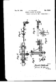
-`Numeral'26 indicates a shoe. Its rear end yis provided with a horizontal'arm 27, also it y pivot29 upon which the shoe is mounted,
said pivotal mounting for the shoe being between the inner ends of said members 27 and 28,' and when the shoe is manufactured said members 27 and 28 may be constructed integral therewith if desired, but if produced separately said members 27 and 28 are secured rigidly with the shoe and have no movements independently of the shoe. i
y Numeral 30 indicates, an equalizing-bar and, as best shown in Figs. 1 and 5 of the drawings its rear end is pivotally mounted by means of a pin 31 upon an extension of the supporting-plate 19 and therefore this bar 30 may have both vertical and horizontal movements, the centers of their arcs of movement being the pivotal mountings of their respective rear ends. v y
It will be noted, that the distance between the pivots 17 and 31 is approximately equal to the length ofthe horizontal arm `27, and therefore when the carrier-beam is swung either to the right or left of the line of traction said members 16 and 30 will remain parallel with each other. Also it will be noted that during the horizontal movements of these bars they `may move toward each other or the reverse.
Numeral 32 indicates a supporting-bar which is hingeably mounted `on the shoe as indicated at 33, and upon the outer end of the bar 32 is 'ournalled a pair of discs 34, these two discs eing identified as a guide-member adapted to travel in a furrow 35. The bar 32 is ivoted to the hinge 33 `as indicated at x. y umeral 36 indicates a brace or flexible member or chain which is secured at its outer end to the bar 32, its inner end being mounted on a hook 37, and it will be understood that the chain 36' may be adjusted longitudinally.
lfhiismember 36 is for the purpose of resist- `mggstresses directed to the guide-member 34 during operation while the tractor is moving forwardly so that the bar 32 will be disposed approximately at right-angles to the shoe 26. WhileI have shown and described a chain 26 for the uses mentioned it is obvious that a metallic bar or rod could be substituted therefor and operation would be practically the same.
In operation, no attention of a driver is needed for the tractor except when turning about at the end of a eld. If the furrow 35 leadsin a straight line the line of traction will correspond thereto and the carrier-beam will have no horizontal swinging movement.
I-Iowever, if the furrow has a curvature the carrier-beam 16 will have a horizontal swinging movement and this movement will be communicated to the steering-arm 14 on account of the action of a control-bar 38 which is pivotally connected at its respective ends with said beam 16 and arm 14.
For instance, if the furrow 35 has a curvature to thef\right of the direction of travel ofthe tractor it is obvious that the beam 16 will swing horizonally toward the off side,
and the control-bar 38 will be moved longitudinally in the same direction to cause an outward swinging movement of the front end of the steeringV arm 14, and thislast named movement will cause the tractor to move on a line conforming to the curvature of the furrow. Also it will be noted that regardless of the degree of curvature of a furrow i the shoe will be maintained' parallel with the line of traction, and this feature is of great advantage.
While the tractor is moving forwardly the guide-member 34 will normally remain in `the furrow. The supporting-bar 32 will normally be disposed at right-anglesto the furrow.
The arm 27 of the shoe is pivotally mounted, as indicated at `39 upon the front end of the equalizing-bar 30 which4 operates as a fulcrum, and any horizontal swinging movement of the shoe will be coincidently communicated to tne steering-arm 13 and to the steering mechanism of the tractor. i
In operation, the carrier-beam 16 and equalizing-bar 30 may be disposed in angular rotation to the line` of traction, but accordingr to the present construction, the shoe will at all times be maintained parallel with the line of traction, and this feature is of great advantage since the supporting-bar 32 during operation, will be disposed approximately at right-angles to the furrow 35 so that there will be no tendency for the guide-member to leave the furrow while the tractor is moving.
The control-bar 38 operates to advantage for many purposes as will be seen. When operating in rough ground, either plowing or listing, this bar tends to resist side stresses directed to the shoe, the equalizing-bar and enga carrier-beam, for the reason that it is mounted on the steering arm, and since the latter is pivotally mounted between its ends as indicatedV at 40, stresses directed to either side of these parts will be resisted.
In operation, it is often desirable to have the tractor move very close to the furrow 35 especially if the ground to be plowed or listed is inclined transversely to the line of traction, and the invention includes such a mounting of the steering-arm that this may be accomplished. By referring to Fig. 1 of the drawings it will be seen that the carrier-beam 16, equalizing-bar 30 and steering-arm 14 are disposed approximately parallel with the line of traction and that the control-bar 38 is provided with notches 41. The steeringarm, at its end,`is provided with a downwardly projecting pin 42 adapted to engage in any selected notch 41, and to accomplish this adjustment, a pull-rope 43 is provided. By use of the pull-rope the bar 38 may be swung rearwardly against the force of a spring 44 so that the pin or projection 42 may e in any selected notch of said bar 38. en it is desired that the tractor shall move with its off wheel close to the furrow the pin 42 is disposed in a notch nearer to the free end of the bar 38, the result being that the steering mechanism of the trac'- tor will be changed to cause the tractor, during its movements, to be disposed closely adjacent to the furrow 35, and during the forward travel of the tractor the carrier-beam 16 and equalizing-bar 30 will remain parallel with reference to each other but they will swing and will be inclined toward the near side of the line of traction, that is to say, the tractor and rear ends of members 16 and 30 will be disposed closer to the furrow than before and the front ends of said members 16 and 30 will be dis osed the same distance from the furrow as Eefore.
The adjustments just described for the steering-arm 14 proves to be of importance since tractors are now in general use for plowing and listing ground on hillsides and in valleys and rough and undulating ground.lv
and in such instances these adjustments are always made to cause the tractor to travel at a selected distance from the furrow.
It will be noted that when an adjustment has been made as last described the shoe 26 Vwill be disposed parallel with the line of traction, this feature being of importa-nce so that the brace-member or chain 36, in connection with said shoe will maintain the supporting-bar 32 approximately at right-angles to the line of traction.
It will be seen that the function discharged by the spring 44 is to cause a constant pressure of the control-bar 38 so that it will be pressed forwardly against the pin or projection 42 of the steering-arm. This is simply a matter of convenience and I may dispense with this spring 44 and notches 41, if desired,l and provide other equivalent means. lVhile I prefer the construction as shown and describedvI do not wish to be understood as limiting myself in this respect. Also while I have shown the mounting of the rear end of the equalizing-bar 30 to be near the axle upon the supporting-plate 19 and prefer this construction, it is obvious that this equalizingbar is for the purpose of providing a fulcrum which will pivotally support the end of the arm 27, and I may substitute other means to operate as a fulcrum. Also I may dispense with the use of the bar 28 since it operates simply as a brace to reinforce the arm 27.
When turning about at the end of a eld or when driving upon a highway, the guide or discs 34 must be removed from the furrow, and therefore I provide means for elevating it and for maintaining it in its elevated position. For these purposes I provide a standard 45 which projects upwardly from the rcar end of the shoe and is secured thereto. This standard may be of any suitable construction and may have any suitable height, and as best shown in Fig. 2 of the drawings it, preferably, has a rearward inclination so that it will not be obtrusive when the supporting-bar 32 and its discs 34 have been swung upwardly.
Upon the top of the standard is an inclined head-piece or plate 46 provided with a V-shaped notch 47, and upon the plate 46 is mounted a pair of rollers or pulleys 48. I provide a chain 49 which is secured at one of its ends to the supporting-bar, the opposite end of said'chain being provided, preferably, with a rope or cable 50, and an operator, by use of the rope, may cause the supportingbar and discs to swing upwardly, the chain movingv between the pulleys 48, and one of the links of the chain being caught in the V-shaped notch 47, which operates to maintain the supporting-bar 32 and discs in the elevated position mentioned. Torelease the chain from the notch, an operator shakes the rope in well known manner to cause the chain to swing upwardly from the V-shaped notch and permits the supporting-bar 32 toefether with its discs to swing downwardly. tWhile I have shown and described a pair of pulleys 48, they are simply for the 'purpose of controlling the direction of movement of the chain 49 so that one of the links of the chain will become caught suitably in the notch 47. The use of this notch is important in operation but its shape and proportions may be changed in a manner to vdispense with the use of the pulleys mentioned.
Since the present invention includes such a mounting for the supporting-bar 32 and guide-member 34 that said bar may be swung in a circles arc of 180 degrees for operation at either side of the line of traction the requirement of the standard 45 or an equivalent support for a chain 49 is obvious for successful, convenient operation; According to the present construction, an operator, at a remote distance from and rearwardly of the attachment, by use of the rope 50, may cause the supporting-bar 32 to swing a complete half-circle, and since the standard has an upward and rearward inclination said bar and discs 34 will not move into enggementtherewith during their swinging movements. y
In the modified form of the invention illustratedy in Figs.` 3 and 4 of the drawings, all of the parts remain the same as have been ydescribed except that the shoe 26 together with the supporting-bar 32 with its discs 34 and the chains 32 and 49 are omitted and a shoe 51 is substituted and is mounted to permit horizontal swinging movements on the vertical bolt or pivot-pin 29 already described, said shoe 51 being provided with a yoke 52 to provide bearings for the shaft 53 of a pair of discs 54, said discs operating asa guidemember and adapted to travel in a furrow 55.
The herein described steering attachment for tractors shown in Figs. 3 and 4 of the drawings is used for listing, and it will be understood that a lister (not shownl may be attached to the tractor, rearwardly thereof, and used for cultivating the ground generally or may be used for listing two or more rows vof corn, the operation `being that fur-y rows Will be formed between the rows of corn, and the furrow 55 may be considered as a furrow formed by a lister; and it should be stated that all of the parts heretofore described for steering the tractor, are depended upon during the operation of listing as well as for plowing. 'In operation, if the furrow 55 has a longitudinal curvature, the guide-member or discs 53 which travel therein will cause a lateral swinging movement of the. shoe 51 which will cause a like swinging movement of the carrier-beam 16, and equalizing-bar 30 as well as the steering-arm 14 for steering the tractor, and the shoe 51 will always remain parallel with the line of traction.
When turning about at the end of a field the shoe 51 may be swung upwardly as shown in dotted lines in Fig. 4 of the drawings, the
shoe being adapted to have swingingmovef ments upwardly and downwardly on its pivotal mounting 56, a cable or rope 57 being sef cured to a ring' at the front end of the shoe so that an operator on the ltractor may control the swinging movements mentioned. However, means should be provided for maintaining the shoe in its uppermost position when swung upwardly. I provide a second cable or rope 58 which extends through the ring 59 and is secured at its end to a U-shaped latch 60 which is pivotally mounted on the shoe, and when the shoe is swung downwardly for engagement of its disc in the furrow, the latch is adapted to become caught upon a projection 61 which is mounted on the'yoke and which operates as a catch, a spring 62 being employed and having a connection with the shoe and said latch 60 and which normally presses said latch toward its engaging position with said projection 61. During operation, the guide-member 54 may be lifted from the furrow by use of the pull-ropes, the latch 60 moving from itsk locked position with the projection or catch 61 against the force of the spring 62, and the parts are of such proportions that when the shoe and discs have moved to their uppermost position the latch 60 will become caught on the bolt 29, and the parts will remain in this last named position.
I claim as my invention,
l. In a steering attachment for tractors, a carrier-beam provided with a shoe and mounted on the tractor to permit vertical and horizontal movements, a supporting-bar hingeably mounted on the shoe to permit vertical mo-vements and pivotally mounted on said shoe to permit horizontal movements, a brace-member connected with the supportingbar and mounted on the shoe, a guide member rotatably mounted on the supporting-bar and adapted to travel in a furrow and to move the carrier-beam, a steering-arm connected with the steering mechanism of the tractor, and a control-bar movable with the carrierbeam, detachably connected with said steering-arm for actuating said steering-arm and ,steering mechanism of said tractor.
2. In a steering attachment for tractors, a carrier-beam extending forwardly from and pivotally mounted on the tractor,an equalizing-bar disposed at the side of the carrierbeam and movable therewith, a shoe pivotally mounted on the carrier-beam and fulcrumed 'on the equalizing-bar, a supporting-bar mounted on ,the shoe. a guide-member rotatably mounted on the supporting-bar and adapted to travel in a furrow and to move the supporting-bar, saidshoe and carrier-beam, a steering-arm connected with the steering mechanism of the tractor, and a control-bar movable with the carrier-beam for moving said steering-arm for actuating the steering mechanism of said tractor.
3. In a steering attachment for tractors, a carrier-beam pivotally mounted on the tractor, a steering-arm conneetedwith the steering mechanism of the tractor, a shoe pivotally mounted on the carrier-beam* and provided with an arm, an equaliZing-barpivotally connected with the arm of said shoe and movable wit-h the carrier-beam, a supporting-bar mounted on the shoe, a guide-member mounted on the supporting-bar and adapted to travel in a furrow and cause a movement of the supporting-bar, said shoe and said carrier-beam, and a control-bar movable with the carrier-beam for moving said steeringarm and steeringr mechanism of the tractor.
4. In a steering attachment for tractors, a
carrier-beam and an equalizing-bar each mounted on the tractor to permit horizontal and vertical movements, a steering-arm connected with the steering mechanism of the tractor, a shoe mounted on the carrier-beam to permit horizontal swinging movements therefrom and having an arm pivotallvS7 connected with the equalizing-bar, a supporting-bar hingeably mounted on the shoe, a guide-member rotatably mounted on the supportingbr and adapted to travel in a furrow and cause movements of the supporting-bar, said shoe, said carrier-beam and equaliziug-bar, and a cont-rol-bar movable by the carrierbeam for moving the steering-arm for moving the steering mechanism of the tractor.
5. In a steering attachment for tractors, a
carrier-beam pivotally mounted on the tractor, a steering-arm connected with the steering mechanism of the tractor, a shoe mounted on the carrier-beam and provided with a standard, a supporting-bar hingeably mounted on the shoe, a guide-member mounted on Vthe su porting-bar and adapted to travel in a urrow and to cause a movement of the supporting bar, said shoe and carrierbeam, a chain arranged to engage the standard for removing the guide-member from the furrow, and a control-bar movable with the carrier-beam for actuating the steering-arm and steering mechanism of the tractor.
6. In a steering attachment for tractors, a carrier-beam extending forwardly from and ivotally connected with the tractor, a shoe aving an arm and mounted on the carrierbeam, a standard mounted on the shoe and provided at its top with a V-shaped notch, a supporting-bar mounted to permit swinging movements from the shoe, a steering-arm connected with the steering mechanism of the tractor, a guide-member mounted on the supporting-arm and adapted to travel in a furrow and to cause movements of the supporting-bar, said control-bar movable with the carrier-beam for actuating the steering-arm and steering mechanism of the tractor, and a flexible member connected with the supporting-bar and adapted to be moved in the V- shaped notch for moving the guide-member from said furrow.
7. In a steering attachment for tractors, a carrier-beam and an equalizing-bar each pivotally mounted on and extending forwardl)7 from the tractor, a shoe having an arm fulcrumed on the equalizing-bar, and pivotally mounted on the carrier-beam, a steering-arm connected with the steering mechanism of the tractor. a guide-member arranged to swing from the shoe for engaging in a furrow and adapted to move the shoe, said equalizingbar and carrier-beam, a standard mounted on the shoe and provided with a V-shaped notch, a chain ada ted to be moved in the notch of the standar for lifting a guide-member from the furrow, and a control-bar detachably connected with-said steering-arm, and movable with the carrier-beam for moving said steering-arm. y
8. In a steering attachment for tractors, a carrier-beam pivotally mounted on the tractor and extending ,forwardl steering-arm connected wit the steering mechanism of the tractor, a shoe pivotally connected with the carrier-beam and provided with an arm, an equalizing-bar movable with the carrier-beam and pivotally connected with the arm of said shoe, a guidemember connected with the shoe and adapted to travel in a furrow and to cause movements of the shoe and said carrier-beam, and a contherefrom, a
trol-bar detachably mounted on the steeringf bar and movable withthe carrier-beam for actuating said steering-bar and steering mechanism of the tractor.
' 9. In a steering attachment for tractors, a carrier-beam pivotally connected with the tractor, a steering-arm pivotally mounted between its ends and connected with the steering mechanism of the tractor, a shoe mounted on the carrier-beam, a guide-member mounted on the shoe to permit swinging movements therefrom in a vertical plane and adapted to travel in a furrow and cause movements of said shoe and carrier-beam, means for elevating the guide-member from the furrow, means for maintaining the guide-member in elevated position, and a control-bar connected with the steering-arm and moving with the carrierbeam for moving said steering-arm.
l0. In a steering attachment for tractors, a carrier-beam pivotally connected with and extending forwardly from the tractor, a steering-arm having a projection and connected with the steering mechanism of the tractor, 'a shoe mounted on the carrier-beam, a guidemember mounted to permit swinging movements from the shoe and adapted to travel in a furrow and cause movements of the shoe and carrier-beam, a control-bar provided with notches and adapted to be disposed with one of its notches receiving the projection of the steering-arm, resilient means for pressing the control-bar against the projection of the steering-arm, said control-bar being movable with the carrier-beam for actuating said steeringarm.
11. In a steering attachment for tractors, a carrier-beam pivotally connected with the tractor, a shoe having a horizontal arm and pivotally connected with the carrier-beam, a guide-member connected with the shoe and adapted to travel in a furrow and to move said shoe and carrier-beam, an equalizing-bar pivotally mounted on the arm of said shoe and movable with the carrier-beam, a control-bar provided atA longitudinal intervals with notches, a steering-arm connected with the steering mechanism of the tractor having a projection and adapted to be disposed with its projection engaging in a selected notch of the control-bar and a resilient element tending to press the control-bar against the projection ofr the steering-arm, said control-bar being movable with the carrier-beam for actuating said steering-arm.
12. In a steering attachment for tractors, a carrier-beam mountedon and extending forwardly of the tractor, a shoey mounted on the carrier-beam, a supporting-bar mounted 10 on the shoe to permit horizontal swinging movements, a guide-member mounted on the supporting-bar and adapted to travel in a furrow and to move the carrier-beam, a bracemember connected with the supporting-bar and mounted on the shoe, a steering-arm connected with the steering mechanism of the tractor, and a control-bar movable with the4 carrier-beam and detachabbT connected with the steering-arm for actuating said steeringarm and steering mechanism of the tractor.
FRED L. WILLRGDT.
Publications (1)
| Publication Number | Publication Date |
|---|---|
| USRE17543E true USRE17543E (en) | 1929-12-31 |
Family
ID=2080101
Family Applications (1)
| Application Number | Title | Priority Date | Filing Date |
|---|---|---|---|
| US17543D Expired USRE17543E (en) | Steering attachment fob tractors |
Country Status (1)
| Country | Link |
|---|---|
| US (1) | USRE17543E (en) |
Cited By (1)
| Publication number | Priority date | Publication date | Assignee | Title |
|---|---|---|---|---|
| US5103924A (en) * | 1990-09-10 | 1992-04-14 | Walker Dean B | Mechanically coupled automatic guidance system for agricultural tractors |
-
0
- US US17543D patent/USRE17543E/en not_active Expired
Cited By (1)
| Publication number | Priority date | Publication date | Assignee | Title |
|---|---|---|---|---|
| US5103924A (en) * | 1990-09-10 | 1992-04-14 | Walker Dean B | Mechanically coupled automatic guidance system for agricultural tractors |
Similar Documents
| Publication | Publication Date | Title |
|---|---|---|
| US3990521A (en) | Foldable farm implement with trailing wing oscillation restrictor | |
| US2533804A (en) | Tractor mower hitch | |
| USRE17543E (en) | Steering attachment fob tractors | |
| US1977273A (en) | Tractor guide | |
| US1313880A (en) | Assionob to the dain manttfactubing | |
| US1852537A (en) | Draft attachment | |
| US1988157A (en) | Plow hitch | |
| US1784534A (en) | Tractor pilot structure | |
| US937410A (en) | Harvester and like draft adjustment. | |
| US2240552A (en) | Sweep rake and vehicle therefor | |
| US1047644A (en) | Automatic steering device. | |
| US1328710A (en) | Steering mechanism for traction-engines | |
| US3420316A (en) | Steering improvements for duplex disk tiller | |
| US1419434A (en) | wilson | |
| US2854803A (en) | Mounting means for tractor mountable mower | |
| US1776940A (en) | Steering attachment for tractors | |
| US1787800A (en) | Corner plow | |
| US1290017A (en) | Tractor-propelled harvester. | |
| US1840123A (en) | Tractor guide | |
| US1453553A (en) | Combined plow and planter | |
| US1601095A (en) | Tractor automatic steering attachment | |
| US1257407A (en) | Riding attachment for harrows and the like. | |
| US2113889A (en) | Automatic tractor steering mechanism | |
| US1639246A (en) | Steering attachment for tractors | |
| US1192700A (en) | Engine gang-plow. |