USRE17455E - Vincent g - Google Patents
Vincent g Download PDFInfo
- Publication number
- USRE17455E USRE17455E US17455DE USRE17455E US RE17455 E USRE17455 E US RE17455E US 17455D E US17455D E US 17455DE US RE17455 E USRE17455 E US RE17455E
- Authority
- US
- United States
- Prior art keywords
- core
- apertures
- bars
- linings
- loops
- Prior art date
- Legal status (The legal status is an assumption and is not a legal conclusion. Google has not performed a legal analysis and makes no representation as to the accuracy of the status listed.)
- Expired
Links
- 230000008093 supporting effect Effects 0.000 description 9
- 239000004020 conductor Substances 0.000 description 8
- 238000004804 winding Methods 0.000 description 7
- 238000000034 method Methods 0.000 description 6
- 238000003825 pressing Methods 0.000 description 4
- 235000019227 E-number Nutrition 0.000 description 1
- 239000004243 E-number Substances 0.000 description 1
- 244000107946 Spondias cytherea Species 0.000 description 1
- 230000015572 biosynthetic process Effects 0.000 description 1
- 238000003780 insertion Methods 0.000 description 1
- 230000037431 insertion Effects 0.000 description 1
- 239000011810 insulating material Substances 0.000 description 1
- 238000009413 insulation Methods 0.000 description 1
- 238000004519 manufacturing process Methods 0.000 description 1
- 230000000284 resting effect Effects 0.000 description 1
- 230000000717 retained effect Effects 0.000 description 1
Images
Classifications
-
- H—ELECTRICITY
- H02—GENERATION; CONVERSION OR DISTRIBUTION OF ELECTRIC POWER
- H02K—DYNAMO-ELECTRIC MACHINES
- H02K15/00—Processes or apparatus specially adapted for manufacturing, assembling, maintaining or repairing of dynamo-electric machines
- H02K15/06—Embedding prefabricated windings in the machines
-
- H—ELECTRICITY
- H02—GENERATION; CONVERSION OR DISTRIBUTION OF ELECTRIC POWER
- H02K—DYNAMO-ELECTRIC MACHINES
- H02K15/00—Processes or apparatus specially adapted for manufacturing, assembling, maintaining or repairing of dynamo-electric machines
- H02K15/20—Shaping or compacting conductors or winding heads after the installation of the winding in the cores or machines; Applying fastening means on winding heads
-
- Y—GENERAL TAGGING OF NEW TECHNOLOGICAL DEVELOPMENTS; GENERAL TAGGING OF CROSS-SECTIONAL TECHNOLOGIES SPANNING OVER SEVERAL SECTIONS OF THE IPC; TECHNICAL SUBJECTS COVERED BY FORMER USPC CROSS-REFERENCE ART COLLECTIONS [XRACs] AND DIGESTS
- Y10—TECHNICAL SUBJECTS COVERED BY FORMER USPC
- Y10T—TECHNICAL SUBJECTS COVERED BY FORMER US CLASSIFICATION
- Y10T29/00—Metal working
- Y10T29/49—Method of mechanical manufacture
- Y10T29/49002—Electrical device making
- Y10T29/49009—Dynamoelectric machine
- Y10T29/49012—Rotor
Definitions
- DIVISION B The invention relates to methods of building armatures and has especial reference to armatures of the bar wound type and apparatus necessary for carrying out my improved method.
- the object of the invention is to provide means to facilitate the insertion of a plurality of conductor bars into the apertures of a dynamo electric machine core.
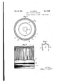
- Fig. 1 is an end view of a core showing winding apertures with insulating linings placed therein.
- Fig. 2 shows the form of conductor loop usually used in carrying out the present invention.
- Fig. 3 shows a core with a plurality of loops assembled ready for endwise entry thru the winding apertures of the core.
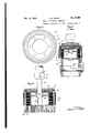
- F i 4 is a plan view of a slotted supporting m m er upon which the core is placed when the conductor loops are pressed thru the core.
- Fig. 5 is a cross section thru a core resting on the supporting member with the conductor loops pressed thru the core and into the slots of the supporting member.
- Fig. 6 is a cross section thru a core and the tool used to withdraw the conductor ends from the slots of the supporting member.
- a core 10 which preferably has closed winding apertures 11 as shown in Fig. 1 tho semiclosed or open slots may be.used instead.
- the core is preferably composed of laminae 12 as shown in Fig. 3.
- a lining 13 of insulating material is placed in each aperture.
- I provide a plurality of winding loops of the character shown at 21, Fi 2, therequired number corresponding to t e number of apertures 11 in core 10.
- These loops are stacked in cylindrical formation, preferably by the method described in my copending reissue application Serial No. 205,259, division A, new Reissue Patent No. 17,353, July 2, 1929 until, in the .2, are slightly entered into the pockets 15 of the linings and all conductor bars 23 of loops 21 Fig. 2, are slightly entered into pockets 16 of the linings. In this form the loops 21 are ready for simultaneousendwise entry into the winding apertures of the core.
- a sup porting member 24 Fig. 4 has radial slots 26 corresponding in number to the core apertures 11 but fitting the conductor barssnugly.
- Fig. 3 The structure shown in Fig. 3 is placed on supporting member 24 with the core apertures 11 in register with the slots 26 of the.
- a pressing member 27 carrying a plate 28 adapted to engage the ends of the loops 21 is brought down and the loops are pressed into place as shown.
- the snug fitting slots 26 admit the bars 22 and 23 but do not admit linings 13. The linings are therefore retained in the core apertures 11 while the conductors are pressed into place.
- Steps in the method of making an armature which consist of providing a core having a pluralityof Winding apertures, lining said apertures with sheet insulation, entering a plurality of winding bars slightly, into one end of the linings, placing the structure on a plate having apertures corresponding to the core apertures but slightly smaller so as to fit the bars snugly, pressing the bars thru the linings and into the plate, then withdrawing the bars from the plate.
Landscapes
- Engineering & Computer Science (AREA)
- Manufacturing & Machinery (AREA)
- Power Engineering (AREA)
- Manufacture Of Motors, Generators (AREA)
Description
Oct." 15, I929. v. G. APPLE METHOD OF BUILDING ARMATURES Original Filed Oct. 11 920 2 Sheets-Sheet 1 INVENTOR Oct; 15, 1929.
V G. APPLE METHOD OF BUILDING ARMATURES Origirial Filed Oct. 11, 1920 2 Sheets-Shet 2 11V VENTOLQ Reissued Oct. 15,
VINCENT G. .AIPLE, OF DAYTON, OHIO 'METHOD OF BUILDING ARMATUBES Original No. 1,555,931, dated October 6, 1925, Serial No. 416,307, filed October 11, 1920; Reissue 17,353, dated July 2, 1929, filed July 12, 1927. Serial No. 205,259. Division A. This application for reissue filed July 12, 1927. Serial No. 205,260.
DIVISION B The invention relates to methods of building armatures and has especial reference to armatures of the bar wound type and apparatus necessary for carrying out my improved method.
The object of the invention is to provide means to facilitate the insertion of a plurality of conductor bars into the apertures of a dynamo electric machine core.
I attain this object by the apparatus illustrated in the accompanying drawings where- 1n Fig. 1 is an end view of a core showing winding apertures with insulating linings placed therein.
Fig. 2 shows the form of conductor loop usually used in carrying out the present invention.
Fig. 3 shows a core with a plurality of loops assembled ready for endwise entry thru the winding apertures of the core.
F i 4 is a plan view of a slotted supporting m m er upon which the core is placed when the conductor loops are pressed thru the core.
Fig. 5 is a cross section thru a core resting on the supporting member with the conductor loops pressed thru the core and into the slots of the supporting member.
Fig. 6 is a cross section thru a core and the tool used to withdraw the conductor ends from the slots of the supporting member.
Similar numerals refer to similar parts thruout the several views.
In putting my invention into practice I provide a core 10 which preferably has closed winding apertures 11 as shown in Fig. 1 tho semiclosed or open slots may be.used instead.
The core is preferably composed of laminae 12 as shown in Fig. 3. A lining 13 of insulating material is placed in each aperture.
After a core has been provided and the apertures lined as shown in Fig. 1, I provide a plurality of winding loops of the character shown at 21, Fi 2, therequired number corresponding to t e number of apertures 11 in core 10. These loops are stacked in cylindrical formation, preferably by the method described in my copending reissue application Serial No. 205,259, division A, new Reissue Patent No. 17,353, July 2, 1929 until, in the .2, are slightly entered into the pockets 15 of the linings and all conductor bars 23 of loops 21 Fig. 2, are slightly entered into pockets 16 of the linings. In this form the loops 21 are ready for simultaneousendwise entry into the winding apertures of the core.
Since linings 13 are not at this stage cemented or otherwise held in the apertures 11 they would ordinarily be pushed from the apertures when the bars are pressed in, and to overcome this tendency I provide means to retain the linings in the apertures while the bars are being pressed into position. A sup porting member 24 Fig. 4 has radial slots 26 corresponding in number to the core apertures 11 but fitting the conductor barssnugly.
The structure shown in Fig. 3 is placed on supporting member 24 with the core apertures 11 in register with the slots 26 of the.
supporting member, then a pressing member 27 carrying a plate 28 adapted to engage the ends of the loops 21 is brought down and the loops are pressed into place as shown. (See Fig. 5.) The snug fitting slots 26 admit the bars 22 and 23 but do not admit linings 13. The linings are therefore retained in the core apertures 11 while the conductors are pressed into place.
Since slots 26 of supporting member 24 fit bars 22 and 23 snugly there is some difficulty in removing the structure from the member and the means provided for withdrawing the structure is shown in Fig. 6. Supporting member 24 is held secured to the press by clamp 29. Plate 28 is removed from pressing member 27 and a mandrel 30 having a hollow head 31 is fitted to the pressing member 27 by means of pin 32 enteringslot 33. The lower end of the mandrel is provided with a fixed attached to the press. When mandrel 30 is i removed from the core the operation which forms the subject of this invention is completed. g
Having described my invention, I claim Steps in the method of making an armature, Which consist of providing a core having a pluralityof Winding apertures, lining said apertures with sheet insulation, entering a plurality of winding bars slightly, into one end of the linings, placing the structure on a plate having apertures corresponding to the core apertures but slightly smaller so as to fit the bars snugly, pressing the bars thru the linings and into the plate, then withdrawing the bars from the plate.
' VINCENT G. APPLhL
Publications (1)
| Publication Number | Publication Date |
|---|---|
| USRE17455E true USRE17455E (en) | 1929-10-15 |
Family
ID=2079945
Family Applications (1)
| Application Number | Title | Priority Date | Filing Date |
|---|---|---|---|
| US17455D Expired USRE17455E (en) | Vincent g |
Country Status (1)
| Country | Link |
|---|---|
| US (1) | USRE17455E (en) |
-
0
- US US17455D patent/USRE17455E/en not_active Expired
Similar Documents
| Publication | Publication Date | Title |
|---|---|---|
| US1555931A (en) | Method of building armatures | |
| US2445986A (en) | Stator winding method and apparatus therefor | |
| US1396033A (en) | Method for making windings | |
| USRE25281E (en) | figure | |
| US2305999A (en) | Method and machine for winding coils | |
| USRE17455E (en) | Vincent g | |
| GB1174350A (en) | Coil Winding and Transfer Apparatus for Dynamoelectric Machine Core Members. | |
| US3522650A (en) | Process for developing wound coils for electromagnetic devices | |
| US2923484A (en) | Coil forming device | |
| US2953309A (en) | Apparatus for and method of winding stator coils | |
| US2575705A (en) | Dynamoelectric machine | |
| US1753554A (en) | Armature-winding apparatus | |
| US1642057A (en) | Armature | |
| US1871751A (en) | Cage making machine | |
| US1222958A (en) | Centrifugal concrete-pole machine. | |
| US1338093A (en) | Armature | |
| US2146868A (en) | Method of and apparatus for | |
| US2875508A (en) | Method of winding armature cores in an apparatus | |
| US1843591A (en) | Armature for dynamo electric machines | |
| US1518209A (en) | Machine for winding loose coils for armatures and the like | |
| US2115570A (en) | Method of winding dynamo-electric machines | |
| US2025795A (en) | Method and apparatus for making a brush for cleaning boiler and condenser tubes and the like | |
| US1743553A (en) | Method and means for forming coil retainers | |
| US946531A (en) | Coil-former. | |
| SU60001A1 (en) | Device for winding coils of electrical machines |