USRE16632E - Automatic braking mechanism for motor cars - Google Patents
Automatic braking mechanism for motor cars Download PDFInfo
- Publication number
- USRE16632E USRE16632E US16632DE USRE16632E US RE16632 E USRE16632 E US RE16632E US 16632D E US16632D E US 16632DE US RE16632 E USRE16632 E US RE16632E
- Authority
- US
- United States
- Prior art keywords
- vacuum
- chamber
- valve
- port
- brakes
- Prior art date
- Legal status (The legal status is an assumption and is not a legal conclusion. Google has not performed a legal analysis and makes no representation as to the accuracy of the status listed.)
- Expired
Links
- 230000001276 controlling effect Effects 0.000 description 4
- 239000000446 fuel Substances 0.000 description 3
- 238000003825 pressing Methods 0.000 description 2
- 241000183024 Populus tremula Species 0.000 description 1
- 238000010276 construction Methods 0.000 description 1
- 210000002445 nipple Anatomy 0.000 description 1
Images
Classifications
-
- B—PERFORMING OPERATIONS; TRANSPORTING
- B60—VEHICLES IN GENERAL
- B60T—VEHICLE BRAKE CONTROL SYSTEMS OR PARTS THEREOF; BRAKE CONTROL SYSTEMS OR PARTS THEREOF, IN GENERAL; ARRANGEMENT OF BRAKING ELEMENTS ON VEHICLES IN GENERAL; PORTABLE DEVICES FOR PREVENTING UNWANTED MOVEMENT OF VEHICLES; VEHICLE MODIFICATIONS TO FACILITATE COOLING OF BRAKES
- B60T15/00—Construction arrangement, or operation of valves incorporated in power brake systems and not covered by groups B60T11/00 or B60T13/00
- B60T15/02—Application and release valves
- B60T15/04—Driver's valves
Definitions
- My invention relates to brakes, more espe cially for motor vehiclesor automobiles, and has for its object, to provide an automatic braking mechanism which is throttle or :10- celerator controlled, forming part of the vacuum system, and throttle controlled either through a hand throttle, lever or. through a foot pedal of the accelerator.
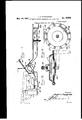
- the invention consists in the features hereinafter described and then sought to be clear-' 1y defined by the claims, reference being had to the accompanying drawings showing the preferred embodiment of the invention, and in which- I Y Figure 1 is a side elevationof a car with portions omitted and illustrating the application. of this invention
- Figure 2 is a side elevation of the vacuum chamberf
- Figure 3 is an end view of Figure 2;
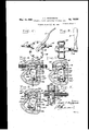
- Figure 4 is a vertical section throughthe vacuum chamber showing position of the port valves'when brakes are set
- Figure 5 is a vertical section showing position of the port valves when the brakes are released'and the car standing at rest;
- Figure 6 is a vertical section showing position of the port valves-when the-brakes Figure"7 is a section on line 7 -7 of Fig-- ure 4;
- Figure 8 1s a. front view of the bralie mechanism diaphragm chamber
- Figure 9 is a section through the chamber and showing a bell crank leverforeonnecting the diaphragm'to the brake rods.
- thenumerall designates a vacuum tank, 2 a carburetor, 3 a manifold, 4 a vacuum lead, pipe, and 5, 6, 7,8 and 9 a conventional representation of a throttle mechanism forcontrollingthe supply offuel or gas for the engine,- which 'sev eral parts may be of any approved well known type and the showing made is suflicient for the purpose of illustrating the ap-' 'plieation of the present invention and therefore need not be more fully illustrated and. described.
- shaft 101 has fixed thereto to'rotate therewith anarm 23, andat one side of arm 23 the shaft carries a loosely. mounted arm formed with a shoulder 25 and'having a valve 26 to controlthe port 27 formed in the casing and opening to atmosphere, and
- the brake mechanism of the car is actuated by or from the vacuum created in the manifold, or'otherwise, and that the control is effected through orfrom manipulation of. the throttle which controls the supply of more or less. gas totthe engine according as it is moved by either the throttle-hand lever on by the accelerator pedal-and thus the operation of the ,b rakemechanism is automatic, following the operation of the throttle i when the Phrase throttle control is used herein it has reference to means 'employed for controlling the supply of the fuel or' gas to.
- vacuum control has reference to a vacuum created throu h the manifold, or otherwise, and em plo ed for appl ing and releasing the brakes or raking mec anism'of the car;
- the brake may be applied. under various degrees of vacuugi ranging from minimum to-maxlmum an held constantly applied under the force of thepressure prevalling at any stage between the minimum and maximum. This is important in that it makes it possible to apply the brake under greater or less power as conditions may make. desirable,. and in holding the brake under such vacuum pressure. It-will further be observed that the tensionon the air cued-proportionately to changes in the degree of vacuum pressure in the. chamber of While I have illustrated and described the '85 inlet control spring 33 is increased or less preferred embodiment of the invention, and
- a braking mechanism for motor ve.-' hicles comprising means for creating a"vacuum, means for applying the vacuum for vacuum to release the brakes, and a throttle control fuel supply cooperatively associated with the vacuum control for applying the vacuum to set the brakes when the throttle is in one position and breaking the vacuum to release the brakes when the throttle is in another position, said braking mechanism including a vacuum chamber provided 'with a valve controlled communication between the chamber and vacuum creating means, and a valve controlling an air inlet port to the chamber, connection one with the other and operable from the throttle-control to exert pressure on the air inlet valve proportional to movement of the ,valve controlling communicauum creating means.
- a braking mechanism for motor vechamber in communication withthe vacuum brake-setting means
- trol operatively connected with said valve to breakthe vacuum between the chamber and the vacuum brake-setting means for re leasing the brake.
- a braking mechanism for motor vehicles comprising a vacuum creating'means, a vacuum brake-setting means, a vacuum chamber having a [valve-controlled communicationwith the vacuum creating means and provided with a vacuum breaking valve, and a throttle control operatively connect- 1 ed with said valves to operate one to control communication between the chamber and I vacuum creating means and to operate the other to break the vacuum in the chamber and the vacuum brake-setting means.
- a braking mechanism for motor vehicles comprising a vacuum chamber connected with brake-setting and release.mech-' anism and having a valve controlled port throughwhicha vacuum is created in the chamber. and a valve-controlled vacuumbreaking port, and means cooperatively conactuating the brakes, means for breaking the said valves having a port in setting tion between the vacuum chamber and vac-- hicles'comprising a vacuum creating means, a vacuum brake-settmgmeans, a vacuum chamber and a valve-controlled vacuumand a throttle con.- breaking port in releasingi ing closure pres nected with said valves to open the vacuum creating port and close the vacuum breaking port in setting the brakes, and to close the vacuum creating port and open the vacuum breaking port in releasing the brakes.
- a braklng mechanism for motor vehicles comprising a vacuum chamber connected with brake-settin and release mechanism and having a va ve controlled port through which a vacuum is created in the chamber and a valve-controlled vacuumbreaking port, means cooperatively connected with said valves to open the vacuum creating port and close the vacuum breaking the brakes, and to close the vacuum creating port and open the vacuum breaking port in releasing the brakes, and means. for exerting, a closure pressure on the vacuum breaking valve proportional to varying vacuum rake-applying pressure in the chamber whereby the brake may be applied and held under pressures ranging between maximum and minimum.
- a braln'ng hicles comprising a vacuum chamber connected with brake-settin and release mechanism and having a va ve' controlled port through which a vacuum is created in the breakingport, means cooperatively connected with said valves to open the vacuum. creating port and close the vacuumbreaking port in setting the brakes, and to close the vacuum creating port and open the vacuum the brakes, and means' for exerting a yiel sure on thevacu um breaking valve proportional to the vacuum pressure in the vacuum chamber whereby the brake may be applied andheld under pressures ranging between maximum and ,minimum,
- a brakingmechanism for motor veuum means for applying the vacuum for setting the brakes, means for breaking the vacuum to release the brakes, a throttle control cooperatively associatedwiththe vacuum control for. a plying the vacuum to set the brakes when t e throttle is inone position and breaking the vacuum to release the JOSEPH c. SNODGRASS.
- hicles comprising means for creating a vac- T
Landscapes
- Engineering & Computer Science (AREA)
- Transportation (AREA)
- Mechanical Engineering (AREA)
- Control Of Throttle Valves Provided In The Intake System Or In The Exhaust System (AREA)
Description
i J. c. SNODGRASS M y 1 AUTOMATIC BRAKING MECHANISM FOR MOTOR CARS 2 Sheets-Sheet 1 ori inal Filed July 20. 1926 altozucq y' 24 1927 J. c. SNODGRASS Re. 16,632
AUTOMATIC BRAKING mgcmmsm FOR moron CARS 2 Sheets-Shee t 2 Original Filed July 26, 19 26 2 Fi .5. W e v Reissued May 24, 1927;
UNITED -,sTAT s;
1 g Rs; 16,632 PATENT. OFF-ICE.
' JOSEPH c. sNonGnAss, or" NASHVILLE; 'rnnnnssnn; assumes. or THREE-mourns 'ro ALBERT R. TALLMAN' ND TWO-EIGHTHS rro BEVERLY n. m xmnm, BOTH or are released;.
NASHVILLE TENNESSEE.
AUTOMATIC 15mins MECHANISM. on MOTOR cans.
Original No. 1,818,236, dated rebmar 'aa, 192,7,Se1'ia1 No. 123,725, filed July 20, 1926. Application for reissue med 4111112; 1927. Serial No. 180,600.
My invention relates to brakes, more espe cially for motor vehiclesor automobiles, and has for its object, to provide an automatic braking mechanism which is throttle or :10- celerator controlled, forming part of the vacuum system, and throttle controlled either through a hand throttle, lever or. through a foot pedal of the accelerator. The invention consists in the features hereinafter described and then sought to be clear-' 1y defined by the claims, reference being had to the accompanying drawings showing the preferred embodiment of the invention, and in which- I Y Figure 1 is a side elevationof a car with portions omitted and illustrating the application. of this invention Figure 2 is a side elevation of the vacuum chamberf V Figure 3 is an end view of Figure 2;
Figure 4 is a vertical section throughthe vacuum chamber showing position of the port valves'when brakes are set;
Figure 5 is a vertical section showing position of the port valves when the brakes are released'and the car standing at rest;
Figure 6 is a vertical section showing position of the port valves-when the-brakes Figure"7 is a section on line 7 -7 of Fig-- ure 4;
Figure 8 1s a. front view of the bralie mechanism diaphragm chamber; I
Figure 9 is a section through the chamber and showing a bell crank leverforeonnecting the diaphragm'to the brake rods.
' In the drawings thenumerall designates a vacuum tank, 2 a carburetor, 3 a manifold, 4 a vacuum lead, pipe, and 5, 6, 7,8 and 9 a conventional representation of a throttle mechanism forcontrollingthe supply offuel or gas for the engine,- which 'sev eral parts may be of any approved well known type and the showing made is suflicient for the purpose of illustrating the ap-' 'plieation of the present invention and therefore need not be more fully illustrated and. described.
Underthe ciated with t e rotatable shaft 10 and ,foot' pedal 11, which may correspond to the foot pedal of an automobile accelerator, a shell or casing 12 supp'ortedby angle-plates 13,
1present invention thereis asso or otherwise, from a suitable part of the car, which has a pipe 141 in communication at one endwith the vacuum portion of the system, say, with the intake of the manifold,
as illustrated, and the other end in com munieation withftheachamber of casing 12, i and another pipe 15 leads from a port 16" of. the casing to a diaphragm-chamber 17 s'upported by angle-plates 18, or o therwise from a suitable part of the car, the flexible diaphragm 19 of the chamber being suitably connected with the brakes of the car, for instance by the linksor rods 20, rocking arm or lever 21, and retracting spring 22. The
shaft 101 has fixed thereto to'rotate therewith anarm 23, andat one side of arm 23 the shaft carries a loosely. mounted arm formed with a shoulder 25 and'having a valve 26 to controlthe port 27 formed in the casing and opening to atmosphere, and
1y mounted on the shaft an arm 28 having a stud or pin 29 in the path of the stud 30 end against apart of the. casing, which may atthe opposite side of arm 23 there is loosel be the/nipple which couples the vacuum lead pipe 15 to the casing, and a spring 33 hears at one end againstthe valve carrying end "of the arm 24 and at the other end against the adjacent end 01 .arm 23, as illustrated in Figures 4 to Tel? thedrawings.
When the throttle is closed and thecar not. running, ports 16 and 27 are closed by thevalves 26"and 31 under the tension of the springs 33 and 32,;respectively, as illustrated in Figure 5. When the car is running, with the foot ofthe operator onthe edal corresponding to the accelerator peda, or
the operator actuates the lever 34 control-- ling the throttle, so as to open the throttle for the feed of fuel or gas, the 'arm' 23 is I moved to the position shown .in Figure 6 and its stud-30bearing against shoulder 25 of arm 24 moves the latter to the position to I open port 27 to break the vacuunr in the chamber of casing 12,;while valve 31 is in position to close port 16, from which pipe 14 leads to the manifold, and held so by the springs 32-so that the vacuum system is cutoflf and vacuum in'casing'chamber 12'and in the valve-diaphragm chamber 17 isv broken in casing 12 derived through its connection" permitting a more or less control: valve 31.0fchamber 12 is o ened' and the brakes placed in'released .ositionhenthe supply of gas' is cut-ofi' from the engine by under the influence of spring 22.
to the position shownin Figure 4 and.
through spring 33 the valve 26 closes port 27, to atmosphere, and arm 28 moves to the position indicatedin Figure 4 by stud 30 of arm 23 pressing against pin 29 of arm 28 so as to open port '16 and permit. the, vacuum with the vacuum system or manifold to ex: ert'itself in the diaphragm chamber 17 and 'on. the flexible diaphragm of that chamber so as to brakes.
pull on the,brake rods and apply the It will be perceived from the foregoing that the brake mechanism of the car is actuated by or from the vacuum created in the manifold, or'otherwise, and that the control is effected through orfrom manipulation of. the throttle which controls the supply of more or less. gas totthe engine according as it is moved by either the throttle-hand lever on by the accelerator pedal-and thus the operation of the ,b rakemechanism is automatic, following the operation of the throttle i when the Phrase throttle control is used herein it has reference to means 'employed for controlling the supply of the fuel or' gas to. theengine for running or operating the car; -and the phrase vacuum control has reference to a vacuum created throu h the manifold, or otherwise, and em plo ed for appl ing and releasing the brakes or raking mec anism'of the car;
Before closing it maybe mentioned. that there is a slight-movement or rocking of the arm 23 under a yielding pressure before its stud 30'is brought into bearing contact with the pin 29 of arm 28 to open valve.31, thus gradual opening and closing of the throttle and also of vacuum control of the braking mechanism without detractingfmm efiicient promptness of action. a.
It will be observed that as the vacuum pressure of arm 23 through spring s e2 erted on the air inlet valve 26 to close the air inletport 27,- and keep thesame closed so that the vacuum pressure wi l he maintained I 2 in order that it may be exerted on the diaphragm 19in d1ain the chamber of easing phra chamber 17 and thus'keep the brake applied under the vacuum pressure trans;
mitted from chamber of casing 12 however small that pressure may he. Then-vacuum pressure in chamber of easing 12increuesj,
whether further opening of the vacuum control valve 31, or otherwise, the, air inlet valve 26 is kept closed against the increased vacuum in the casing chamber by reason of I the increased tension given to spring 33 which is exerted on the air inlet valve 26,
and thus thecbrake will be held applied under theincreased vacuum pressure exerted thereon.-. It-will be noted from the'fore 'oing that the brake may be applied. under various degrees of vacuugi ranging from minimum to-maxlmum an held constantly applied under the force of thepressure prevalling at any stage between the minimum and maximum. This is important in that it makes it possible to apply the brake under greater or less power as conditions may make. desirable,. and in holding the brake under such vacuum pressure. It-will further be observed that the tensionon the air cued-proportionately to changes in the degree of vacuum pressure in the. chamber of While I have illustrated and described the '85 inlet control spring 33 is increased or less preferred embodiment of the invention, and
construction of the individual elements'or units thereof; 1t is to .be understood that changes or variations'jmay be made /therein' without departing from essential features of I the invention 4 r By advancing. the hand lever of the throttle slightly the operation of the parts as described ma be made, for the time, inoperative', an the car may be run independently of the automatic braking mechanism; It will be observed that,'as the vacuum valve 31 of chamber 12 is opened, pressure of arm 23 through spring 33 is exerted on I air inlet valve 26 to a slight degree at first.
The pull of the vacuum being about 12 pounds per square inch, and the spring tension o'nvalve 26 being only 8 ounces at the "beginning of movement, causes valve 26 to leak and tend to practically destroy the vacuum. But as valve-31 continues to open the pressure is Increased on spring 33,,thereby gradually reversing the ratio of air and-vac- When valve 31 is fully open, air -inlet valve 26 is physically closed, thereby-allowing maximum pressure .(viz, 12 pounds per square inch) to be 3 ezgerted on diaphragm. By wa of explanation: If -v acuum valve 31 is hel half open, ou wouldonlyet a pressure of6 pouns per square =1nc if held one-third open you would get 4 pounds per square inch. etc; V a
' avinggdescribd *m invention and set forth its merits, what. claim is:
1.- A braking mechanism for motor ve.-' hicles comprising means for creating a"vacuum, means for applying the vacuum for vacuum to release the brakes, and a throttle control fuel supply cooperatively associated with the vacuum control for applying the vacuum to set the brakes when the throttle is in one position and breaking the vacuum to release the brakes when the throttle is in another position, said braking mechanism including a vacuum chamber provided 'with a valve controlled communication between the chamber and vacuum creating means, and a valve controlling an air inlet port to the chamber, connection one with the other and operable from the throttle-control to exert pressure on the air inlet valve proportional to movement of the ,valve controlling communicauum creating means.
means,
2. A braking mechanism for motor vechamber in communication withthe vacuum brake-setting means,
a valve controlled port to the vacuum chamber,
trol operatively connected with said valve to breakthe vacuum between the chamber and the vacuum brake-setting means for re leasing the brake.
4. A braking mechanism for motor vehicles comprising a vacuum creating'means, a vacuum brake-setting means, a vacuum chamber having a [valve-controlled communicationwith the vacuum creating means and provided with a vacuum breaking valve, and a throttle control operatively connect- 1 ed with said valves to operate one to control communication between the chamber and I vacuum creating means and to operate the other to break the vacuum in the chamber and the vacuum brake-setting means. f
'5. A braking mechanism for motor vehicles comprising a vacuum chamber connected with brake-setting and release.mech-' anism and having a valve controlled port throughwhicha vacuum is created in the chamber. and a valve-controlled vacuumbreaking port, and means cooperatively conactuating the brakes, means for breaking the said valves having a port in setting tion between the vacuum chamber and vac-- hicles'comprising a vacuum creating means, a vacuum brake-settmgmeans, a vacuum chamber and a valve-controlled vacuumand a throttle con.- breaking port in releasingi ing closure pres nected with said valves to open the vacuum creating port and close the vacuum breaking port in setting the brakes, and to close the vacuum creating port and open the vacuum breaking port in releasing the brakes.
6. A braklng mechanism for motor vehicles comprising a vacuum chamber connected with brake-settin and release mechanism and having a va ve controlled port through which a vacuum is created in the chamber and a valve-controlled vacuumbreaking port, means cooperatively connected with said valves to open the vacuum creating port and close the vacuum breaking the brakes, and to close the vacuum creating port and open the vacuum breaking port in releasing the brakes, and means. for exerting, a closure pressure on the vacuum breaking valve proportional to varying vacuum rake-applying pressure in the chamber whereby the brake may be applied and held under pressures ranging between maximum and minimum.
-7. A braln'ng hicles comprising a vacuum chamber connected with brake-settin and release mechanism and having a va ve' controlled port through which a vacuum is created in the breakingport, means cooperatively connected with said valves to open the vacuum. creating port and close the vacuumbreaking port in setting the brakes, and to close the vacuum creating port and open the vacuum the brakes, and means' for exerting a yiel sure on thevacu um breaking valve proportional to the vacuum pressure in the vacuum chamber whereby the brake may be applied andheld under pressures ranging between maximum and ,minimum,
8. A brakingmechanism for motor veuum, means for applying the vacuum for setting the brakes, means for breaking the vacuum to release the brakes, a throttle control cooperatively associatedwiththe vacuum control for. a plying the vacuum to set the brakes when t e throttle is inone position and breaking the vacuum to release the JOSEPH c. SNODGRASS.
hicles comprising means for creating a vac- T
Publications (1)
| Publication Number | Publication Date |
|---|---|
| USRE16632E true USRE16632E (en) | 1927-05-24 |
Family
ID=2078431
Family Applications (1)
| Application Number | Title | Priority Date | Filing Date |
|---|---|---|---|
| US16632D Expired USRE16632E (en) | Automatic braking mechanism for motor cars |
Country Status (1)
| Country | Link |
|---|---|
| US (1) | USRE16632E (en) |
-
0
- US US16632D patent/USRE16632E/en not_active Expired
Similar Documents
| Publication | Publication Date | Title |
|---|---|---|
| US3574413A (en) | Brake system for vehicles | |
| US2313430A (en) | Brake control mechanism | |
| US1548394A (en) | Vehicle braking system | |
| USRE16632E (en) | Automatic braking mechanism for motor cars | |
| US2871999A (en) | Brake control system | |
| US2325771A (en) | Throttle brake control mechanism | |
| US1858999A (en) | Vacuum power clutch | |
| US2362723A (en) | Brake mechanism | |
| US1618236A (en) | Automatic braking mechanism for motor cars | |
| US2152949A (en) | Fluid pressure brake system | |
| US1633360A (en) | Throttle-control apparatus for brake-applying mechanism | |
| US1811994A (en) | Power actuator | |
| US2186332A (en) | Braking mechanism | |
| US1845995A (en) | Brake actuating mechanism | |
| US1501146A (en) | Air brake for automobiles | |
| US1946127A (en) | Vacuum brake system for automotive vehicles | |
| US1841708A (en) | Brake mechanism for automotive vehicles | |
| US1044898A (en) | Fluid-pressure-controlling system for motor-vehicles. | |
| US2262844A (en) | Brake | |
| US1742444A (en) | Vacuum brake | |
| USRE20910E (en) | Fluid pressure brake | |
| US2039095A (en) | Automobile brake | |
| US1741820A (en) | Brake mechanism for automotive vehicles | |
| US1609057A (en) | Speed regulator for motor vehicles | |
| US1908400A (en) | Brake system for automotive vehicles |