USRE1492E - Improvement in harvesting-machines - Google Patents
Improvement in harvesting-machines Download PDFInfo
- Publication number
- USRE1492E USRE1492E US RE1492 E USRE1492 E US RE1492E
- Authority
- US
- United States
- Prior art keywords
- rake
- reel
- post
- main frame
- wheel
- Prior art date
Links
- 239000010902 straw Substances 0.000 description 10
- 230000000153 supplemental Effects 0.000 description 10
- 240000000218 Cannabis sativa Species 0.000 description 4
- 230000004048 modification Effects 0.000 description 4
- 238000006011 modification reaction Methods 0.000 description 4
- 238000010408 sweeping Methods 0.000 description 4
- 229940091292 Alo Drugs 0.000 description 2
- 210000003746 Feathers Anatomy 0.000 description 2
- 239000004020 conductor Substances 0.000 description 2
- 238000003306 harvesting Methods 0.000 description 2
- 210000001699 lower leg Anatomy 0.000 description 2
- 230000000414 obstructive Effects 0.000 description 2
- 230000000284 resting Effects 0.000 description 2
- 238000004804 winding Methods 0.000 description 2
Images
Definitions
- KIRBY KIRBY, OF BUFFALO, AND DAVID M. OSBORNE, OF AUBURN, NEW YORK, ASSIGNEES OF SAID WM.
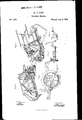
- FIG. l represents a perspective view of the machine,taken from the front, and looking obliquely toward the main frame and drivinggear.
- Fig. 2 represents a perspective view of the machine, taken from the rear of the main frame, and looking toward the outside divider.
- Fig. 3 represents a portion of the rake-gearing detached, and on an enlarged scale to better show its action.
- Fig. 4 represents a side view of" the main frame and main drive-wheel, to
- Fig.5 represents a modification of the device for throwing the rake in and out of gear with the driving-gear of the machine.
- A represents a main frame, to which the finger-bar, cutting apparatus, platform, reel, and a portion of the driving-gear are connected and B is a supplemental or segmental frame pivoted to the main frame A, this frame B having the main driving and supporting wheel 0, as well as the drivers seat, connected with it, and also some of the gearing.
- a rake-post, F is hinged at c to a projecting portion of the main frame A, the hinge-joint being so arranged as that said rake-post may swing toward or from the grain side of the platform, but not in the A connecting rod or bar, G, is pivoted tothe rakepost F at the poin t d, and its otherend is pivoted to a wrist-pin, c, of the crank D, so that this crank and connecting-rod define the swinging motion of the said rake-post-that is to say, the extentof its motion.
- the fork in going toward the outside divider first rises and advances in a curved line, and then descends to the outer side of the platform but in returning it sweeps the stalks off from the platform, leaving them in a compact gavel on the ground. If the rake were allowed a continuous motion, the gavels gathered by it would be of difierent sizes and i ered.
- the boss has grooves cut in it, which slip over or upon feathers on the shaft b, and when the arm K is in one of the notchesf the shaft 1) is set in motion and operates the rake; but when the arm K is thrown out of its notch,or any of them, it moves. the boss back and uncouples the gear a from the shaftb, and then the rake instantly stops, although the gear it continues to run with the main drive-wheel.
- a lever,-M which extends from near the drivers seat to a point near the perimeter of the gear a, where it is hinged, as at g, to a toggle-trigger, k, that is pivoted at t to the supporting-piece N, so
- the driver can control the motion of the rake at his will, either keeping it in or out of action constantly, or periodically, as circu1n-- stances may require.
- ' O is a reel-post, bolted to the main frame at l, sothat it may, when it becomes necessary to swing the reel farther into, toward, or from the standing grain, be moved on this bolt or fastening.
- a guide and supporting-piece,P is connected to the main frame, or to the uprights Q R on the main frame, and has a curved slot, on, in it, so that by means of a nut and bolt, 12, the reel-post may be adjusted and supported by this guide-piece. This makes the reel -post rigid and firm when adjusted, and the nuts are run up onto the bolts.
- a yoke, t is formed or connected to this slide, and has two bearings-,1) 19, one upon each of its ends, in which the reel-shaft U is supported and turns, and thus the use of an outside reel post is avoided.
- the reel-shaft and the reel are driven from a pulley, g, by means of an endless belt, 8, passing around it and around a loose pulley, t, on an arm, a, near the top of friction to drive the reel, while the reel may be raised or lowered without any adjustment of the belt or any disarrangement of it.
- the tension of the belts be changed by turning the reel-post on its bolt l, as said bolt is in the plane of the center of the pulley q.
- the rake or fork E traverses parallel to and just behind the finger-bar, so that it comes against the butt ends of the straws and sweeps them toward the gaveling-space at the mainframe side of the platform, and this side, WV, is made oblique, so that the heads ofthe stalks which lie toward the rear of the platform will.
- the supplemental frame B that carries the drive-wheel (J, is pivoted or hinged to the main frame at a point, t, which point is also the center of the pinion w, that'is driven by the main drive-wheel, so that the latter, as it rises and faHs, rolls around the pinion and always I I which they or any of their connected parts to the other.
- the cogged gear Y on the drive-wheel 0 runs close to the ground, and is liable to be injured by stones or other obstructions, or to become clogged with dirt, straws, grass, 850. So, also, the pinion w is liable to damage, and
- guard or shield is devised to protect them.
- This guard or shield could not be on the main frame,-because the drive-wheel rises and falls independent of said main frame; or said main frame must be raised or lowered sometimes on the auxiliary frame to'regulate the height of the cutters, and one would interfere with or fail to be a protection
- the shield Z is cast or permanently attached to the supplemental frame by means of arms at. It'curves around in close proximity to the periphery of the cog-gear Y,
- the shield is also extended around the pinion w to protect it also. This can be done, notwithstandingthis pinion is on the main frame, because the center of motion of the I supplemental frame to whichthe shield is attached and the center of motion of the pinion are one and the same, and hence the curved,
- FIG. 5 is represented a modification of the devices for throwing the rake in and out of gear with the machine.
- a spring-lever, 1, is
Description
I w. 'A. KIRBY. Harvesting Machine.
Reissued Jun 9. 1863.
Wwzessas:
UNITED STATES WILLIAM A.
PATENT OFFICE.
KIRBY, OF BUFFALO, AND DAVID M. OSBORNE, OF AUBURN, NEW YORK, ASSIGNEES OF SAID WM. A. KIRBY.
IMPROVEMENT IN HARVESTING-MACHINES.
Specification forming part of Letters Patent No. 32,736, dated July 2, 1861; Reissue No. 1,492 dated June 9, 1863.
DIVISION A.
To all whom it may concern: V
Be it known that WILLIAM A. K-IRBY, of Bufl'alo,iu the county of Erie and State of New York, (lid invent certain new and useful Improvements in Harvesting-Machines and the Raking Apparatus thereof 5 and we do hereby declare that the following is a full, clear, and
exact description thereof, reference being had to the accompanying drawings, making a part of this specification, in which- Figure l'represents a perspective view of the machine,taken from the front, and looking obliquely toward the main frame and drivinggear. Fig. 2 represents a perspective view of the machine, taken from the rear of the main frame, and looking toward the outside divider.
7 Fig. 3 represents a portion of the rake-gearing detached, and on an enlarged scale to better show its action. Fig. 4 represents a side view of" the main frame and main drive-wheel, to
show the manner of arranging the shield on the frame to protect the gearing that runs close to the ground. Fig.5 represents a modification of the device for throwing the rake in and out of gear with the driving-gear of the machine.
Similar letters ofreference, where they 00- rest, and be raised high enough as it moves toward the outside divider to avoid the falling grain and drop beyond the stalks on the platform preparatory to sweeping them off; and, finally, it consists in combining with an automatic rake a lever, trigger, and clutch-arm, so that the driver at his seat may stop or set the rake in motion at his will, or set the trigger so that it will stop the rake after making one operation.
To enable othersskilled in the art to make line of the motion of the machine.
and use this part of the said KIRBYS invention, we will proceed to describe the same with reference to the drawings.
A represents a main frame, to which the finger-bar, cutting apparatus, platform, reel, and a portion of the driving-gear are connected and B is a supplemental or segmental frame pivoted to the main frame A, this frame B having the main driving and supporting wheel 0, as well as the drivers seat, connected with it, and also some of the gearing. These things are shown, described, and some of them claimed in patents heretofore granted to said KIRBY, and need not be referred to in detail in this specification.
There is attached to the main drive-wheel O a bevel-pinion that turns with the drive-wheel. This pinion gears and turns abevel-gear,a ,on one end of a shaft, 1), the other end of said shaft having a crank,'D, upon itfor operating the rake E, as follows: A rake-post, F, is hinged at c to a projecting portion of the main frame A, the hinge-joint being so arranged as that said rake-post may swing toward or from the grain side of the platform, but not in the A connecting rod or bar, G, is pivoted tothe rakepost F at the poin t d, and its otherend is pivoted to a wrist-pin, c, of the crank D, so that this crank and connecting-rod define the swinging motion of the said rake-post-that is to say, the extentof its motion. To the top of the rake-post is pivoted the shankor handle H of the rake or fork E,'this shank extending beyond its pivoted point, and at or near its end having a pitman,- I, connected with it, which pitman also extends to and is connected with the wrist-pin cof the crank D, so that the crank D gives a com pound motion to the rakeby swinging the rake-post toward and from the outside divider-or fence by means of the pitman G, and causing it to rise and fall, and then be drawn back over the platform mainly by the pitman I, but partially by the pitman G. The fork in going toward the outside divider first rises and advances in a curved line, and then descends to the outer side of the platform but in returning it sweeps the stalks off from the platform, leaving them in a compact gavel on the ground. If the rake were allowed a continuous motion, the gavels gathered by it would be of difierent sizes and i ered.
in bad condition to be bound, and hence I have arranged so that the rake shall be thrown out of motion at every. revolution of its gear-wheel, and 0e held out of motion, at the will of the driver or conductor, until sufficient grain has accumulated on theplatform to make apropersized gavel, when it isthrown into action again and sweeps the platform. This is done as follows: On the hack of the bevel-gear wthere are a series of teeth or notches,f, and upon the shaft 1) there is a sleeve or boss,J, which has an arm, K, upon it, and this boss and arm are thrown up toward the teeth of the wheel a by a spring, L. The boss has grooves cut in it, which slip over or upon feathers on the shaft b, and when the arm K is in one of the notchesf the shaft 1) is set in motion and operates the rake; but when the arm K is thrown out of its notch,or any of them, it moves. the boss back and uncouples the gear a from the shaftb, and then the rake instantly stops, although the gear it continues to run with the main drive-wheel.
To throw out the arm K, a lever,-M,is used, which extends from near the drivers seat to a point near the perimeter of the gear a, where it is hinged, as at g, to a toggle-trigger, k, that is pivoted at t to the supporting-piece N, so
that when the lever M is in the position shown in Fig. 1 and in black in Fig. 4 the rake will continue to run; but when the lever M is dropped, as shown in red in Fig.3, the trigger h is thrown out, and when the arm K comes around to it it (the-arm) will come in contact with the trigger and be forced out of its tooth in the wheel and rest upon the trigger, in-
' stantly stopping the rake-shaft, crank, and
rake itself. \Vhen enough stalks have accumulated on the platform to make a gavel the driver again draws up the lever M, and the arm K, being released, is thrown into one of the notchesf by the spring L and the rake is again in motion. Thereis a guide-arm,j,near the upper end of the lever M, and two notches,
1 2, in the lever itself. If the lever be secured to the guide j by its notch 1, the rake will be thrown out of action, and remain out so long as this notch or connection be used; but if the lever be secured by its notch 2 to the guide j the rake will be in action, and so remain in action as long as this connection is maintained.
Thus the driver can control the motion of the rake at his will, either keeping it in or out of action constantly, or periodically, as circu1n-- stances may require.
'Itis stated that the rake-post was connected to the main frame, but driven from the main wheel, which is on the supplemental frame,
and the main frame is raised and lowered, and sometimes left free to raise and lower it-' self in conforming to the inequalities in the surface of the ground, or in fixing the height at which the cutters are to work. This being the case, provision must be made to allow the fork or rake to follow the plat-formas it is raised or lowered, without cramping the gear, which is not correspondingly raised or low- This is accomplished by means of a universal joint, 70, in the rake-shaft I), which allows the two frames all their requisite play or adjustment, and leaves the rake free to accommodate itselfto the platform at any of its positions.
' O is a reel-post, bolted to the main frame at l, sothat it may, when it becomes necessary to swing the reel farther into, toward, or from the standing grain, be moved on this bolt or fastening. A guide and supporting-piece,P, is connected to the main frame, or to the uprights Q R on the main frame, and has a curved slot, on, in it, so that by means of a nut and bolt, 12, the reel-post may be adjusted and supported by this guide-piece. This makes the reel -post rigid and firm when adjusted, and the nuts are run up onto the bolts. Upon the reel-post is fixed or placed a buckle or slide, S, which, for convenience, is clamped to the post at any proper height by a cam-lever, 0, which makes the slide easy of adjustment on the reel-post. A yoke, t, is formed or connected to this slide, and has two bearings-,1) 19, one upon each of its ends, in which the reel-shaft U is supported and turns, and thus the use of an outside reel post is avoided. The reel-shaft and the reel are driven from a pulley, g, by means of an endless belt, 8, passing around it and around a loose pulley, t, on an arm, a, near the top of friction to drive the reel, while the reel may be raised or lowered without any adjustment of the belt or any disarrangement of it. Nor will the tension of the belts be changed by turning the reel-post on its bolt l, as said bolt is in the plane of the center of the pulley q.
The rake or fork E traverses parallel to and just behind the finger-bar, so that it comes against the butt ends of the straws and sweeps them toward the gaveling-space at the mainframe side of the platform, and this side, WV, is made oblique, so that the heads ofthe stalks which lie toward the rear of the platform will. arrive at'the edge thereof while the buttends are still on the receiver or platform y, and the moment the heads come in contact with the stubble, the machine advancing, the gavel is drawn off onto the ground in good shape for binding, or, rather, the stubble holding ontothe heads of the grain, the machine passes out from under the gavel, and hence there is no dribbling of the straws, as is the casew'hen the gavel is thrown off by mechanism that is advancing with the machine and continues to deliver the straw as it advances.- I
The supplemental frame B, that carries the drive-wheel (J, is pivoted or hinged to the main frame at a point, t, which point is also the center of the pinion w, that'is driven by the main drive-wheel, so that the latter, as it rises and faHs, rolls around the pinion and always I I which they or any of their connected parts to the other.
may for the time being be moving.
- The cogged gear Y on the drive-wheel 0 runs close to the ground, and is liable to be injured by stones or other obstructions, or to become clogged with dirt, straws, grass, 850. So, also, the pinion w is liable to damage, and
' particularly to the catching and winding up of straws, grass, &c. To prevent these difficulties and annoyances a guard or shield is devised to protect them. This guard or shield could not be on the main frame,-because the drive-wheel rises and falls independent of said main frame; or said main frame must be raised or lowered sometimes on the auxiliary frame to'regulate the height of the cutters, and one would interfere with or fail to be a protection The shield Z is cast or permanently attached to the supplemental frame by means of arms at. It'curves around in close proximity to the periphery of the cog-gear Y,
and thus protects-it from injury-or from clogging. The shield is also extended around the pinion w to protect it also. This can be done, notwithstandingthis pinion is on the main frame, because the center of motion of the I supplemental frame to whichthe shield is attached and the center of motion of the pinion are one and the same, and hence the curved,
' tion of the shield also.
There are several other parts of the machine which are not specially described; but theyare shown in the drawings, and itis notdeemed important to describe them here, as they are described, and some of them claimed, in other patents granted to the said KIRBY or his as'- signees.
By using an overhanging reel, as herein shown, we dispense with theuse of any reelsupporter on the outside of the machine, such outer reel-supporters being liable to entangle or get entangled in the grain, and thus obstruct the free passage of the machine.
When the machine is to be used without the rake attaehmenta rakers seat, A, 'may be attached to the machine, as represented in Fig. 4, the front end of the seat-supporter being secured to the standard R by means of the bolt a, said supporter resting also on the frame of the machine, as at b.
' In Fig. 5 is represented a modification of the devices for throwing the rake in and out of gear with the machine. A spring-lever, 1, is
pivoted at 2 to the crank K. The end of this spring-lever is pressed in between the cogs f of the bevel-wheel a, and is disengaged from said bevel-wheel by means of the lever M, the lower end of which is provided with a camslot, 3, through which the bolt 4 passes' By this arrangement the piece It, as shown in Fig.
3, may be dispensed with. Having thus fully described this part of the invention, what is claimed therein as the in vention of WILLIAM A. KIRBY is 1. In combination with an automatic rake in a reaping-machine, a hinged reaching-post and two connecting-rods operated from one and the same crank for the purpose of giving said rake its motions, substantially as described.
/ 2. Hinging and supporting the rake-post on the main frame and inclining it backward, so that the rake will be out of the way of the falling grain when at rest and be raised high enough as it moves, toward the outside divider to avoid the falling grain and drop beyond the stalks on the platform preparatory to sweeping them off, substantially as described.
3. In combination with an automatic rake, the lever, trigger, and clutch-arm, substan-- tially as described, so that the driver at his seat may stop or set the rake in motion at his will, or set the trigger so that it will stop the rake after making one operation, as described.
WM. A. KIRBY.*
D. M. OSBOIftNE.
Witnesses:
JOHN H. Osnoanu, Cults. H. GARLOCK.
Family
ID=
Similar Documents
| Publication | Publication Date | Title |
|---|---|---|
| USRE1492E (en) | Improvement in harvesting-machines | |
| US32736A (en) | Improvement in harvesting-machines | |
| US206834A (en) | Improvement in grain-binders | |
| US215680A (en) | Improvement in grain-binders | |
| US75797A (en) | Improvement in harvesters | |
| US148790A (en) | Improvement in harvester-droppers | |
| US52351A (en) | Improvement in harvesters | |
| US187616A (en) | Improvement in harvesters | |
| US769937A (en) | Pea-harvester. | |
| US180004A (en) | Improvement in reapers and mowers | |
| USRE2465E (en) | Improvement in harvester-rakes | |
| US32828A (en) | Improvement in harvesters | |
| US319717A (en) | Grain-binding harvester | |
| US109469A (en) | Improvement in harvester rakes | |
| USRE3411E (en) | Improvement in grain and grass harvesters | |
| US726508A (en) | Machine for harvesting corn. | |
| USRE8119E (en) | Improvement in harvester-rakes | |
| USRE8144E (en) | Improvement in harvesters | |
| US329931A (en) | Grain-binding harvester | |
| US266866A (en) | Self-binding harvester | |
| US72349A (en) | Improvement in harvesting-machines | |
| USRE388E (en) | Improvement in reaping-machines | |
| US251221A (en) | Grain-binder | |
| US824825A (en) | Harvester. | |
| US118996A (en) | Improvement in harvesters |