USRE12496E - Siphon-closet - Google Patents
Siphon-closet Download PDFInfo
- Publication number
- USRE12496E USRE12496E US RE12496 E USRE12496 E US RE12496E
- Authority
- US
- United States
- Prior art keywords
- outlet
- water
- pipe
- chamber
- siphon
- Prior art date
Links
- XLYOFNOQVPJJNP-UHFFFAOYSA-N water Substances O XLYOFNOQVPJJNP-UHFFFAOYSA-N 0.000 description 64
- 230000000694 effects Effects 0.000 description 18
- 239000000203 mixture Substances 0.000 description 14
- 230000000414 obstructive Effects 0.000 description 10
- 239000000463 material Substances 0.000 description 6
- 238000010276 construction Methods 0.000 description 4
- 239000012530 fluid Substances 0.000 description 4
- 241000282619 Hylobates lar Species 0.000 description 2
- 241000218652 Larix Species 0.000 description 2
- 235000005590 Larix decidua Nutrition 0.000 description 2
- 241001237728 Precis Species 0.000 description 2
- 240000003748 Salicornia europaea Species 0.000 description 2
- 239000011521 glass Substances 0.000 description 2
- 230000004048 modification Effects 0.000 description 2
- 238000006011 modification reaction Methods 0.000 description 2
- 239000002244 precipitate Substances 0.000 description 2
- 239000004576 sand Substances 0.000 description 2
- 239000007787 solid Substances 0.000 description 2
- 239000003643 water by type Substances 0.000 description 2
Images
Definitions
- This invention has reference to siphon appagttus for water-closets and it is an objectt ereof to furnish a construction in which discharge outlet shall be of relatively large area throughout :its entire length,'so as to successfully pass obstructive materials of considerable mass, also to accomplish this result without the introduction of internal projections or providing the outlet with me-' cha'm'cal strictures or such other obstructive 'deyices'intrpducedin or extendin into the outlet of the discharge-pipe as wou d tend to clog the same and interfere with the movement-of the outgoing stream or catch up and stop any masses of material.
- N W YORK, N. Y., ASSIGNOR To AMERICAN OF NEW YORK. N. 1 A CORPORATION OF SlPH ON-GLOSET.
- said portion 9 of the outletipe may be as large, or nearly as large, as t 'This important result is also accomplished,
- Figs. 1 and 2 the dotted lines 19 20 indicate the pipe 4, continued from portion 6 to the portion 9 in line therewith. It may be here remarked that the first part of thestream of water coming down through the pipe (when the outlet-pipe'i's vertical, aspreerred in ractice) encounters'in the enlargement or c iamber a body of air normally stationary, and it is obvious the first effect of the descending water against such body of air will be to somewhat compress the air in the upper portion of said chamber, and thus tend to spread and divert the same, this action of the air being immediately opposed-by the relatively large surface at 2 1 There are thus set up within the chamber movements of air-currents somewhat com lex in character, but having as the result t ereof an impeding action on the incoming water.
- choke as used the claims I mean any kind of a choke which does not define itself with thewall' line of the outlet-pipe. i
- A- feature ofmy improvement isth'at the discharge-conduitcomprises two. pi -sections of similar form and size, one lh cated above the other, but the two located al'mement, the interior- .of the conduit-sections communicating with an enlarged chamber combined with a laterally-disposed wall located outside of-th'e zone-of-the-conduit-opening or theinterior-wallof said conduit, and which-form's an a ron-orsplash-base for-deflecting the do owing stream into a plane transverse to the longitudinal axis ofthe-conduit, whereby this transverse flow creates a water-seat, upon which may pile other Waters emanating. from the inner-zones, so as to form a solidified water-plug, which .when' of'proper-weight so precipitates as to pro prise efiicient si honic action.
- a siphon water comprising two pipe-sections which are each at no point of less caliber in cross-section than the siphoning-passage in the bowl, and between which sections is provided an enlargement having a reflecting-surface at the base thereof so positioned as to receive the impact of the water as it passes through the enlargement and sufficiently abrupt to cause argement and sufliciently abrupt to cause the v water reflected therefrom to impede the flow of water through the outlet, whereby a choking effect is produced to establish siphonic action.
- a water-closet bowl having a si honpassage therefrom the outletor down eg of which is provided with an enlarged portion or chamber separating such outlet into anupper and a lower portion, such upper portion eing at no point of substantial y less crosssectional area than'the inlet-passage in the bowl, the bottom of said chamber being inpo sition to receive the im act of the water as i passes through the out et and sufficiently ab rupt to impede the flow of water through such outlet, whereby a choking effect is produced to establish siphonic action, the wall of the lower portion of such outlet running from the inner edge of the bottom wall of such chamber.
Description
REISSUED JUNE LE, 1906.
13. U- TILDEN. SIPHON CLOSET.
APBLHJATIOH FILED MAR. 30, 1905.
mfiwsses: fizz/mim- (A 3 Bar! aim lldm,
- y his fllforneyM underneath the bowl my present improvements, however, the pipe be carried more directly and then car. lie down vertically, if so desired.
4 A11 embodiment of the pres n inve n Be "it known that I, -eitize n of the United States, residing in New York, borough of Brooklyn, in the county of the I} parts'throu UNITED STATES PATENT OFFICE.
rear o t-JEN. TILDE 0F. SANITARY WORKS,
NEW YORK.
' No; 770.027. dated-september 13, 1004.
To all zit-may concern:
Kings and State of New York, have invented certain new and useful Improvements in Sihon-Closets, of which the following is a specication.
This invention has reference to siphon appagttus for water-closets and it is an objectt ereof to furnish a construction in which discharge outlet shall be of relatively large area throughout :its entire length,'so as to successfully pass obstructive materials of considerable mass, also to accomplish this result without the introduction of internal projections or providing the outlet with me-' cha'm'cal strictures or such other obstructive 'deyices'intrpducedin or extendin into the outlet of the discharge-pipe as wou d tend to clog the same and interfere with the movement-of the outgoing stream or catch up and stop any masses of material.
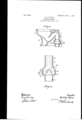
prior practices it has been common to reducethe outlet to form a choke, thereby 'to' more surely obtain thefwater-plug of sufii cient solidity to accomplish the siphoning action necessary to the proper operation 0 the closet. For accoml'ph'shng these objects the discharge-pipe of t e usual siphon form and arrangement is led out of the closet and then passes upward to .form the upper bend and then downwardand inwardly for the purpose more especially of bringing it to'a desirable position fortaking away the stream of the closet. With isset forth on the accompanying sheet of drawin s, whereon' j Q i ure 1 illustrates a sectional view of a bow with the improvement applied, and Fig. .2 isa' diagrammatic illustration of the action I of he stream in the outlet at the point of improvem'ent. p
Similar characters of reference indicate like bout the figures, p The bow -'s represented by 1, from which at 2 proceeds an outlet comprisin a siphoning passageor inlet or upleg an an outletpassa e ,or downleg 4, having an enlarge ment, "(indicated a general way at -5,) so
; Specification of Reissued- Letters Patent. I
Bnn'r OLEN TILDE N, a
N W YORK, N. Y., ASSIGNOR To AMERICAN OF NEW YORK. N. 1 A CORPORATION OF SlPH ON-GLOSET.
I that the stream of water in coming down the portion 6 of the pipe 4 when it'reaches the point 7 naturally egins to spread, and itwill neissuedsuneiaisoe. Application for reissue filsii ll larch 30, 190.6 Serial No. 309,005,
then strike upon the abutment portion 8 of the enlargement or chamber 5. Thel wate'r striking upon said part 8 is naturally deflected and retarded in its movement, and the Water obstruction thus resulting to the oncom ing stream from the portion 6 tendsflal'l the more to fillthfe outward partof the chamber 5 with fluid, which in its turn tends further to obstruct the stream coming downthr ough the portion 6, and in connection withthis ac-v tion that portion 95 of the water directly dfi .fiected laterally toward the center of the pi'pefromth'e abutment-face 8 tends toform a fountain or water obstruction extending entirely across th'epipe and whichso'coacts with the incoming stream itself (obstructed and retarded, as ,already referredto) as to slow up the velocity of the water'immediately below in the portion 9 of the pipe, and thus form in that portionof the' pipe asolid stream."
notwithstanding. that the, said portion 9 of the outletipe may be as large, or nearly as large, as t 'This important result is also accomplished,
e upper portion 6. In this way any masses of material which will readily pass from the bowl throughthe outlet at 2 may be successfully passed through the entire length of the pipe, and so finallydisposed of without liability of the outlet-pipe becoming choked or blocked thereby at any portion in its length due to mechanical strictures in the outlet. In this way I form a water-plug in a ipe of relatively large size,.which plug will ro in a solid body through that portion 9 o the pipe 4, thus drawingdown the air as the plug preci itates and creates avacu um in 0 tion 6 o the said pipe 4. Thus an important feature accomplished in' thislipe fromthe improvement is that the outletomt Where it leaves the bow to, where it nall'y" enters the main pipe canbe of unrew I striated size throughout. v largement -of the outlet-pipe into ,a chamber would bring in the princl le in hydraulics (at least when the pipe is fiill offiuid) that the passageof a stream of a given velocity from a relatively small pipe into a largerpipe or chamber tends to re-forin the stream into one of'lar 'er diameter of lesser velocity and that this arger stream passing farther along The [sudden enthe conduit until it again enters the smaller j pipe at the point of such entrance again tends to re-form itself in a small stream whose velocity is equal to the reduction in the size of the stream.
The principle upon which my present improvement operates I a prehend is in sub stantial accordance wit the principle diagrammatically illustrated in Fig. 2. For instance, if'that portiontfi of pipe 4 be a pipe of, say, three-inch diameter and if the portion 6 be in line with and a continuation" of said portion 9, the two pipes being connectedby a large chamber, as 5, then water flow ng through the portion 6 at a' speed, for instance,
of ten feet in a given period will re-form on entering the chamber'5 into a stream of Cl1fiGI'-'-' ent size and-velocity. These speeds will of course be approximately roportionate, to the areas of the pipes, whic in the instance illustrated are about in the proportion of seven to nineteen, respectively-that is to say, the stream flowing through the portion 6 at a speed often feet per second :would normally re-form into a stream in the chamber 5 on the first discharge through the portion 6;
with a velocity of less than four feetzper second. In practice of course the stream does not instantaneously become a sohd stream but this com arison will serve to illustrate the principle l y which the water entering the pipe 9 from the larger portion 50f the conduit normally 0 erates to effect a fluid obstruction or c oke without the use of any reduction of the pi e and without the employment of any mechanical stricture or like device to interpose into the line of the pipe.
It will be noted that no mechanical ob struction is introduced within the conduit and no shoulder or device is made to project in any wise into the line of the outlet-pi e. The peculiar action of the apparatus y which the hydraulic choke is created is an action that is entirely different than would result from the introduction of any projection or abutment into the line of the conduit. It
will be observed that a very important'and' practical advantage of my resent improvement is that a complete sip onic action may be quickly and effectively produced in a vertical pipe without curves or bends an'd also freev of any mechanical choke orrestriction.
In Figs. 1 and 2 the dotted lines 19 20 indicate the pipe 4, continued from portion 6 to the portion 9 in line therewith. It may be here remarked that the first part of thestream of water coming down through the pipe (when the outlet-pipe'i's vertical, aspreerred in ractice) encounters'in the enlargement or c iamber a body of air normally stationary, and it is obvious the first effect of the descending water against such body of air will be to somewhat compress the air in the upper portion of said chamber, and thus tend to spread and divert the same, this action of the air being immediately opposed-by the relatively large surface at 2 1 There are thus set up within the chamber movements of air-currents somewhat com lex in character, but having as the result t ereof an impeding action on the incoming water. For illustration of one feature of this peculiar action of the inclosed airI have drawn the fine lines at. 22, indicating what I deem to be the probable lines' of resistance at the moment referred to within the mass of air in the air-- chamber, especially with regard to its tendency to flow out ofsaid chamber into the portion 9-, which lines, it will be noted, follow somewhat the arrangement of the, similar lines which are. understood-to beformedfin the case of sand flowingfout of'theordinary hour-glass.
By the term choke as used the claims I mean any kind of a choke which does not define itself with thewall' line of the outlet-pipe. i
A- feature ofmy improvement isth'at the discharge-conduitcomprises two. pi -sections of similar form and size, one lh cated above the other, but the two located al'mement, the interior- .of the conduit-sections communicating with an enlarged chamber combined with a laterally-disposed wall located outside of-th'e zone-of-the-conduit-opening or theinterior-wallof said conduit, and which-form's an a ron-orsplash-base for-deflecting the do owing stream into a plane transverse to the longitudinal axis ofthe-conduit, whereby this transverse flow creates a water-seat, upon which may pile other Waters emanating. from the inner-zones, so as to form a solidified water-plug, which .when' of'proper-weight so precipitates as to pro duce efiicient si honic action.
I'do not con e myself-to the precise construction and shape of'the outlet-as hereinshown and within the purview ofthis inventionmay resort to various modifications.
Having thus described'my invention, I claim- 1. The combination with a siphon watercloset=bowl, ofan outlet-passa e therefromwhich is at no point of less cali er=in cross: section than thesiphoning-passage in the bowl, which outlet contains an interior-enlargement provided with a reflectin -s'u rface in position to receive-the impact-of t e water as it passes through the enlargement and suffi'ciently abruptto causethe water reflected therefrom to impede the 'fio'w ofwater through the outlet, whereby a choking effect is produced to establish siphonic action-.-
2. The combination with asiphon Watercloset bowl, of-an outlet-passage therefrom which is at no point of less caliber in crosssection than the. siphoning-passage in the bowl, which outletembodies an interior-ens largement provided with a reflecting-surface located at the base of the enlargement and'inposition to receive theimpactofthe-water-asit passes through the enlargement and sufficiently abrupt to cause the water reflected therefrom to impede the flow of water through the outlet, whereby a choking effect is produced to establish siphonic action. 3. The combination with a siphon water comprising two pipe-sections which are each at no point of less caliber in cross-section than the siphoning-passage in the bowl, and between which sections is provided an enlargement having a reflecting-surface at the base thereof so positioned as to receive the impact of the water as it passes through the enlargement and sufficiently abrupt to cause argement and sufliciently abrupt to cause the v water reflected therefrom to impede the flow of water through the outlet, whereby a choking effect is produced to establish siphonic action.
5. The-combination with a siphon Watercloset bowl, of an outlet-passage therefrom which is at no point of less caliber in crosssection than the siphoning-passage in the bowl, which outlet embodies an interior enlargement provided with a reflecting-surface communicating with the lower portion of the outlet and in position to receive the impact of the water as it passes through the enlargement and sufficiently abrupt to cause the water reflected therefrom to impede the flow of water through the outlet, whereby a choking effect' is produced to establish siphonic action.
6. In a siphon water-closet, the combine; tion-with a bowl, of an outlet-passage'and an enlarged chamberfo'rmed integral thereone portion of the passage-and communicating with another portion through an abrupt her being at no point of substantially less cross-sectional area than. the inlet-passage in the bowl.
. 7. Ina siphon water-closet, thecombination with a bowl of an outlet, an enlargement situated in said outlet, the wall of the enlargement gradually proceeding from one portion other portion thereof as to form an abrupt shoulder effective to establish siphonicaction closet bowl, of an outlet-passage therefrom.
with, said chamber gradually flaring from.
shoulder effective to establish siphonic action, the outlet-passage above the enlarged cham of the outlet and so communicating with an a part'of which shoulder is outside of the in-.
terior line of the wall of said outlet at any point thereof above and below said enlarge 1 ment.
8. The combination with a siphon waterprovi ed with a reflecting-surface in position: to receive the impact of the water as it passes throu h the outlet and sufficiently abrupt to m e e the flow of such water through the'wy out et whereby a choking effect is provided to establish siphonic action, the outlet-passage above and below the enlargedchamber each being of substantially'uniform crosssectional area throughout its length.
9. The combination with a siphon watercloset bowl, of an outlet-passa e therefrom widened out intermediate its en s to form an enlargement or chamber with an abrupt bottom wall forming an annular reflecting-surface in position to receive the im act of the water as it passes through the out et and sufficiently abrupt to im ede the flow of such Water through the out et whereby a choking effect is provided and si honic action first established in. the region 0 such bottom wall. 10. A water-closet bowl having a si honpassage therefrom, the outletor down eg of which is provided with an enlarged portion or chamber separating such outlet into anupper and a lower portion, such upper portion eing at no point of substantial y less crosssectional area than'the inlet-passage in the bowl, the bottom of said chamber being inpo sition to receive the im act of the water as i passes through the out et and sufficiently ab rupt to impede the flow of water through such outlet, whereby a choking effect is produced to establish siphonic action, the wall of the lower portion of such outlet running from the inner edge of the bottom wall of such chamber.
11. A siphon water-'closet bowl having a siphon-passage therefrbm the outlet-passageor downleg of which is widened out to", pro vide an enlargement or chamber having a deflectin -surface in position to receive the impact 0 the water as it, passes through such outlet and sufliciently abru I t to impede the flow of such water through t e outlet thereb' to establish siphonic action, the areaof sub outlet-passage: being approximately not less at any point than substantially equal to the face to establish siphonic'action.
.70 closet bowl, of an outlet-passage therefrom havin therein an enlargement or chamber 13. The combination with a siphon water- I 14. In a siphon water-closet, the combinecloset bowl, of a siphon member havingan tion with a bowl, of a siphon member having I outlet-passagewidened out intermediate its an outlet-passage widened out intermediate ends to form a chamber having greater diamits ends to form an enlargement or chamber I 5 5 eter than any other part of the outlet-passage provided with an abrupt surface effective to above and below such chamber, and having deflect the water and establish siphonic ac-' a reflecting-surface in position to receive the tion,
impact of the water as it passes through the BERT OLEN TILDEN. outlet-passage and sufficiently abrupt to im- Witnesses: 1o Bede the flow of such water thereby to estab- O. P. WEED,
sh siphonic action. F. E. BOYCE.
Family
ID=
Similar Documents
| Publication | Publication Date | Title |
|---|---|---|
| US1647189A (en) | Self-cleaning flushing valve | |
| US333935A (en) | Egbert d | |
| USRE12496E (en) | Siphon-closet | |
| US406977A (en) | Soil or sewer pipe flushing device | |
| US1676035A (en) | Nozzle | |
| US770027A (en) | Siphon-closet. | |
| US1999493A (en) | Hydraulic valve | |
| US201758A (en) | Improvement in sewer and other traps | |
| US988787A (en) | Closet-bowl. | |
| US829462A (en) | Ball-cock. | |
| US716856A (en) | Slow-closing valve. | |
| US770129A (en) | Trap. | |
| US669193A (en) | Device for supplying water to flush-tanks. | |
| US848365A (en) | Siphon. | |
| US791889A (en) | Discharge device. | |
| US845520A (en) | Settling-tank. | |
| US110087A (en) | Improvement in stench-traps | |
| US788454A (en) | Non-siphonable self-scouring trap. | |
| US721685A (en) | Flush-tank feeder and cleaner. | |
| SU859537A1 (en) | Apparatus for retaining alluviums | |
| US2297533A (en) | Cross t connection | |
| US431384A (en) | Water-trap | |
| US827324A (en) | Sewer-gas trap. | |
| US240655A (en) | Flushing and cleaning sewers | |
| SU84476A1 (en) | Hydraulic ram |