USH1522H - Laser-modulated aerosol infrared decoy - Google Patents
Laser-modulated aerosol infrared decoy Download PDFInfo
- Publication number
- USH1522H USH1522H US07/627,393 US62739390A USH1522H US H1522 H USH1522 H US H1522H US 62739390 A US62739390 A US 62739390A US H1522 H USH1522 H US H1522H
- Authority
- US
- United States
- Prior art keywords
- aerosol
- infrared
- light
- decoying
- infrared sensors
- Prior art date
- Legal status (The legal status is an assumption and is not a legal conclusion. Google has not performed a legal analysis and makes no representation as to the accuracy of the status listed.)
- Abandoned
Links
Images

Classifications
-
- G—PHYSICS
- G02—OPTICS
- G02B—OPTICAL ELEMENTS, SYSTEMS OR APPARATUS
- G02B26/00—Optical devices or arrangements for the control of light using movable or deformable optical elements
- G02B26/02—Optical devices or arrangements for the control of light using movable or deformable optical elements for controlling the intensity of light
-
- F—MECHANICAL ENGINEERING; LIGHTING; HEATING; WEAPONS; BLASTING
- F41—WEAPONS
- F41H—ARMOUR; ARMOURED TURRETS; ARMOURED OR ARMED VEHICLES; MEANS OF ATTACK OR DEFENCE, e.g. CAMOUFLAGE, IN GENERAL
- F41H11/00—Defence installations; Defence devices
- F41H11/02—Anti-aircraft or anti-guided missile or anti-torpedo defence installations or systems
Definitions
- the invention relates to a method and apparatus for defeating an attack by an infrared-seeking missile, and in particular to a system wherein an aerosol of particles that undergo a photochemical reaction is illuminated with a laser image.
- the laser illumination initiates the photochemical reaction to produce heat that decoys the infrared-seeking missile away from the target.
- a simple defensive technique against infrared seeking missiles is to deploy a screening cloud of dust or smoke to obscure the ship.
- smoke screens take a long time to deploy, and thus their use requires a relatively early warning.
- Smoke screens also require a large quantity of aerosol material. Screening clouds have the further disadvantage of blinding the ship as well as the attacking missile.
- Rapidly deployable infrared decoys would make target acquisition more difficult for the infrared seeking missile.
- infrared decoys must fulfill in order to be effective. First, they must be as bright as the largest ships are in the wavelengths detected by the missile (approximately 10 kw/steradian)--existing missile infrared detectors measure the 3 to 5 ⁇ m and 8 to 12 ⁇ m bands.
- the decoys must be rapidly deployable to allow their use only when an incoming missile is detected. The decoy must produce its bright output for at least one minute so as to attract an infrared-seeking missile during its approach.
- the decoy's infrared image must have a spectral content that resembles a blackbody with a temperature of about 20° to 50° C. above ambient temperatures.
- the decoy will also present its infrared image on an appropriate spatial scale so as to mislead not only present but also anticipated future advanced sensing systems. No existing decoy system possesses all of these features.
- flares are very bright, they emit a spectrum characteristic of a very hot blackbody (greater than 1,000° C.) rather than a blackbody of about 20° to 50° C. above ambient temperatures. That is, unlike a blackbody with a relatively equal energy output across its spectrum, the majority of the flare's energy is output at wavelengths in a narrow band.
- a method and apparatus that creates an alternate infrared target comprised of an aerosol of particles capable of undergoing a photochemical reaction to produce heat.
- a high powered light initiates the reaction by projecting upon the aerosol a life-size image.
- the light induced reaction releases heat that creates a life-size image with an appropriate blackbody temperature and brightness.
- the heated aerosol becomes a decoy target which mimics the size and the infrared signature of a target.
- lasers with different wavelength light illuminate a non-reactive aerosol.
- the aerosol can be made to look like a blackbody to the missile's infrared detector system.
- FIG. 1 is a schematic representation of the present invention.
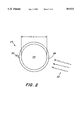
- FIG. 2 is a schematic representation of an individual particle from the aerosol of an alternative embodiment.
- FIG. 1 shows a schematic representation of an embodiment of the present invention.
- a ship at sea 10 can avoid a direct hit from an infrared seeking missile 12 by deploying an exploding canister 14.
- Canister 14 disperses an aerosol 18.
- Dispersed aerosol 18 is illuminated by light source 16 which projects beam 22 to create a life-sized image 20 of the ship.
- the required energy is preferably provided by the chemical energy stored in an aerosol.
- This chemical energy is controllably released when the particles are selectively illuminated.
- the level of reaction initiated, and thus the amount of heat released, will be proportional to the brightness of light source 16: the photochemical reaction amplifies the energy in light beam 22.
- the ratio of chemical energy to light energy typically must be greater than 100. Preferably, the ratio will approach about 10,000.
- Illumination by beam 22 initiates a photochemical reaction which amplifies the energy in image 20 to decoy infrared-seeking missile 12.
- the two most crucial elements in this system are: the photochemical particles which make up aerosol 10; and light source 16, most desirably a laser, which projects an intense image onto aerosol 10 to initiate the photochemical reaction.
- a laser is preferred for light source 16 because it can be selected to deliver an intense light at the wavelength which most efficiently initiates the selected photochemical reaction.
- any light source capable of generating a sufficiently intense image at the proper wavelength is suitable.
- the image is painted on the aerosol by a conventional projection-scanning system such as those found in popular "laser-color" shows. Because all the light energy is concentrated on a small area of the aerosol, a lower power light source 16 is acceptable.
- a light initiated slow photochemical reaction such as an auto-oxidation, free radical, polymerization, or other reaction, can release enough heat to create an infrared source. Ideally, the heat would be released in proportion to the incoming UV illumination provided by the laser.
- An example of the free radical reaction is: ##EQU1##
- the primary function of aerosol 18 is not to merely providing a "screen" on which a decoy image 20 can be projected. Rather, the aerosol provides a spatially dispersed source of chemical energy which can be used to develop an infrared, decoy image.
- reaction is strongly exothermic (approx. 20 kcal/mole)
- the reaction is expected to provide this invention with an energy ratio of 1,000.
- 100 kg of 400 micrometer diameter liquid droplets were illuminated by a 1 kw UV laser, upwards of 1 MW of chemical energy will be released. Of this amount, approximately 70% will be lost due to thermal conduction to the surrounding air.
- the lost heat is insufficient to raise the air temperature to the desired 20° to 50° C. above ambient temperature. Even if the air did become hot enough, air does not have the right emissivity to act as an infrared source. Thus, it is the remaining 30% of the energy--which raises the temperature of the aerosol particles by about 50° C.--that causes an increase of approximately 10 kw/steradian in the blackbody brightness in the 8-12 ⁇ m band.
- Any aerosol with a sufficiently exothermic reaction responsive to a controlled illumination can also be employed in this embodiment.
- About 200 to 500 kg of liquid benzaldehyde would be a suitable quantity of reactant for this embodiment.
- Alternative aerosols with more exothermic reactions could significantly reduce the weight and volume of reactant required.
- Iron is an example of a more exothermic, alternative reactant.
- FIG. 2 shows an individual particle 24 from the aerosol of an alternative embodiment.
- Core 26 comprises a material capable of an exothermic, oxidation reaction; this small particle would instantaneously oxidize if it were exposed to air.
- Layer 28 is relatively impermeable to oxygen: atmospheric oxygen 30 cannot reach the particle's reactant core 26.
- Light 22 photochemically alters layer 28 and increases its oxygen permeability allowing oxygen 30 to reach reactant 26 and initiate oxidation. However, even in its altered state, layer 28 limits the rate at which oxygen can reach the reactant core 26: the limited oxygen availability creates a low temperature oxidation reaction that can continue for more than a minute.
- the light photochemically modulates the oxygen permeability of layer 28. Therefore, light 22 photomodulates the infrared intensity of decoy aerosol 18.
- the iron core 26 is initially isolated from atmospheric oxygen 30 by an impermeable plastic layer 28.
- plastic layer 28 undergoes a photochemical change that increases its oxygen permeability.
- layer 28 passes enough oxygen to heat the particles to 20° to 50° C. above the ambient temperature. If the diameter D of particles 24 is large enough--about 100 ⁇ m--the particle will generate heat for several minutes. However, the size and density of the particle must also assure that the aerosol does not settle too quickly. Otherwise, the aerosol will not be present during an attacking missile's final approach.
- Iron is a desirable reactant for the core because, as it reacts with air, it does not form an effective passivating layer that prevents further oxidation of the remaining iron.
- More energetic metals such as aluminum
- These metals can be used if made up of a cluster of small spheres where each sphere has a radius less than the thickness of that metal's passivating layer. These small spheres will be attracted to each other by Van Der Waals forces; clusters of these spheres can then be coated by impermeable layer 28.
- the invention can use high efficiency metals such as boron, calcium, aluminum, and silicon.
- layer 28 is made from polyethylene it only passes enough oxygen to raise the temperature of the particle by about 1° C.
- the cross-linking of polymers following ultraviolet excitation will lead to more than an order of magnitude increase in the oxygen permeability of layer 28. Because the atmosphere filters out short wavelength ultraviolet, normal daylight does not have significant amounts of 250 nm light. Control light 22 will not be swamped by daylight.
- Another alternative embodiment uses infrared lasers 16 to paint a 2 or 3-wavelength infrared image on an aerosol 18 whose particles scatter the laser light.
- infrared lasers 16 to paint a 2 or 3-wavelength infrared image on an aerosol 18 whose particles scatter the laser light.
- This projection approach will take advantage of the relatively unsophisticated nature of existing infrared-seeking missiles spectral testing. Some of these missiles detect all wavelengths of infrared light; other missiles discriminate against hot flares by a two wavelength test (for example, determining the ratio of a 3-5 micron light versus 8-12 micron light). In principle, because of infrared sensitivity limitations and the presence of only a few infrared atmospheric windows, it will be difficult for infrared seekers to use sophisticated spectral filtering.
- an infrared image can be displayed to attract an infrared-seeking missile.
- the image produced in accordance with the present invention will faithfully mimic that of a ship and thus will distract sensors employing sensing means other than infrared.
- Other sensors would include various imaging schemes or spectral filters.
- the embodiments of the present invention can thus be used to protect ships against present and future infrared-seeking missiles.
Landscapes
- Engineering & Computer Science (AREA)
- Physics & Mathematics (AREA)
- Aviation & Aerospace Engineering (AREA)
- Radar, Positioning & Navigation (AREA)
- Remote Sensing (AREA)
- General Engineering & Computer Science (AREA)
- General Physics & Mathematics (AREA)
- Optics & Photonics (AREA)
- Aiming, Guidance, Guns With A Light Source, Armor, Camouflage, And Targets (AREA)
Abstract
A system for protecting ships from attack by an infrared-seeking missile is provided which comprises decoying the missile by deploying an aerosol. In one embodiment, the aerosol merely scatters a modulated light beam. Another embodiment deploys particles that can undergo an exothermic photochemical reaction when initiated by an ultraviolet laser. The laser projects an image of the ship onto the aerosol and at the same time causes the particles to generate sufficient heat to attract the infrared-seeking missile away from the ship. This system presents an infrared-decoy target with a suitable infrared image of appropriate spatial scale to mislead a missile with imaging capability. The spectral content of the decoy's image resembles that of a blackbody 20°-50 ° C. above ambient, and has a brightness and spatial extent equal to the largest ships, approximately 10 kw/steradian, in the 3-5 and 8-12 micrometer bands. The present invention is simple to use, rapidly deployed, and capable of presenting a decoy target that can last at least a minute or more.
Description
The invention relates to a method and apparatus for defeating an attack by an infrared-seeking missile, and in particular to a system wherein an aerosol of particles that undergo a photochemical reaction is illuminated with a laser image. The laser illumination initiates the photochemical reaction to produce heat that decoys the infrared-seeking missile away from the target.
An important problem currently facing the Navy is the protection of their ships from missile attack. At present, surface ships are vulnerable to infrared seeking missiles which home-in on a large, bright infrared source such as a ship. It is desirable that these ships be able to defeat a missile attack by means such as decoying an approaching missile so that it misses its target.
A simple defensive technique against infrared seeking missiles is to deploy a screening cloud of dust or smoke to obscure the ship. However, smoke screens take a long time to deploy, and thus their use requires a relatively early warning. Smoke screens also require a large quantity of aerosol material. Screening clouds have the further disadvantage of blinding the ship as well as the attacking missile.
Rapidly deployable infrared decoys would make target acquisition more difficult for the infrared seeking missile. There are essential requirements that infrared decoys must fulfill in order to be effective. First, they must be as bright as the largest ships are in the wavelengths detected by the missile (approximately 10 kw/steradian)--existing missile infrared detectors measure the 3 to 5 μm and 8 to 12 μm bands. The decoys must be rapidly deployable to allow their use only when an incoming missile is detected. The decoy must produce its bright output for at least one minute so as to attract an infrared-seeking missile during its approach. Additionally, the decoy's infrared image must have a spectral content that resembles a blackbody with a temperature of about 20° to 50° C. above ambient temperatures. Ideally the decoy will also present its infrared image on an appropriate spatial scale so as to mislead not only present but also anticipated future advanced sensing systems. No existing decoy system possesses all of these features.
Currently, the Navy deploys flares to distract infrared-seeking missiles, but flares have several problems. Although flares are very bright, they emit a spectrum characteristic of a very hot blackbody (greater than 1,000° C.) rather than a blackbody of about 20° to 50° C. above ambient temperatures. That is, unlike a blackbody with a relatively equal energy output across its spectrum, the majority of the flare's energy is output at wavelengths in a narrow band.
Sensors monitoring the relative intensities at several wavelengths can immediately recognize and disregard such a flare. While the infrared wavelengths put out by flares can be modified by altering their chemistry, it appears to be very difficult to make the flare look like a cooler blackbody over its complete spectrum. Another problem associated with flares is that their output is usually too spatially localized to appear ship-like. It remains likely that heat seeking missiles will be able to distinguish between decoy flares and ships.
Another approach being developed is to deploy an aerosol of particles that undergo chemical reaction or phase changes upon deployment. The reaction causes the aerosol to release heat for a short period of time. This approach has not been successful because the particles burn and cool down too quickly (in less than 10 seconds).
There have been attempts to use chemical or aerosol screens in order to decoy an infrared-seeking missile target or to attenuate infrared signals or laser light. For example, a camouflaging aerosol that can cause a false target effect within the infrared range is disclosed in U.S. Pat. No. 4,406,815 (Magnusson et al). Pyrotechnic devices in compositions for producing an infrared blocking screen are disclosed in U.S. Pat. Nos. 4,728,375 (Simpson), 4,719,856 (Joslin), and 4,719,857 (Spring). Finally, systems for attenuating or dissipating laser light energy are disclosed in U.S. Pat. Nos. 4,673,250 (Roberts et al), and 3,992,628 (Karney). However, none of these systems can effectively and reliably decoy incoming infrared-seeking missiles.
It is an object of this invention to decoy an infrared seeking missile with an aerosol.
It is a another object to have the aerosol have an infrared emission spectrum similar to a large blackbody 20° to 50° C. above ambient temperature.
It is another object of this invention to have the infrared emission from the aerosol continue for several minutes.
It is a further object of this invention to be able to control the spatial dispersion of infrared emissions from the aerosol.
These and other objects are provided by a method and apparatus that creates an alternate infrared target comprised of an aerosol of particles capable of undergoing a photochemical reaction to produce heat. A high powered light initiates the reaction by projecting upon the aerosol a life-size image. The light induced reaction releases heat that creates a life-size image with an appropriate blackbody temperature and brightness. The heated aerosol becomes a decoy target which mimics the size and the infrared signature of a target.
In another embodiment, lasers with different wavelength light illuminate a non-reactive aerosol. By adjusting the ratio between the intensities of the different illuminating wavelengths, the aerosol can be made to look like a blackbody to the missile's infrared detector system.
FIG. 1 is a schematic representation of the present invention.
FIG. 2 is a schematic representation of an individual particle from the aerosol of an alternative embodiment.
FIG. 1 shows a schematic representation of an embodiment of the present invention. A ship at sea 10 can avoid a direct hit from an infrared seeking missile 12 by deploying an exploding canister 14. Canister 14 disperses an aerosol 18. Dispersed aerosol 18 is illuminated by light source 16 which projects beam 22 to create a life-sized image 20 of the ship.
To achieve the infrared brightness necessary to effectively decoy an infrared seeking missile, several megawatts of continuous energy must be projected by the aerosol for a minute or more. Because most lasers cannot supply the necessary level of energy, the required energy is preferably provided by the chemical energy stored in an aerosol. This chemical energy is controllably released when the particles are selectively illuminated. The level of reaction initiated, and thus the amount of heat released, will be proportional to the brightness of light source 16: the photochemical reaction amplifies the energy in light beam 22. Even with high powered light sources, the ratio of chemical energy to light energy typically must be greater than 100. Preferably, the ratio will approach about 10,000.
Illumination by beam 22 initiates a photochemical reaction which amplifies the energy in image 20 to decoy infrared-seeking missile 12. The two most crucial elements in this system are: the photochemical particles which make up aerosol 10; and light source 16, most desirably a laser, which projects an intense image onto aerosol 10 to initiate the photochemical reaction.
A laser is preferred for light source 16 because it can be selected to deliver an intense light at the wavelength which most efficiently initiates the selected photochemical reaction. However, any light source capable of generating a sufficiently intense image at the proper wavelength is suitable. Preferably, the image is painted on the aerosol by a conventional projection-scanning system such as those found in popular "laser-color" shows. Because all the light energy is concentrated on a small area of the aerosol, a lower power light source 16 is acceptable.
A light initiated slow photochemical reaction, such as an auto-oxidation, free radical, polymerization, or other reaction, can release enough heat to create an infrared source. Ideally, the heat would be released in proportion to the incoming UV illumination provided by the laser. An example of the free radical reaction is: ##EQU1##
Thus, in this embodiment, the primary function of aerosol 18 is not to merely providing a "screen" on which a decoy image 20 can be projected. Rather, the aerosol provides a spatially dispersed source of chemical energy which can be used to develop an infrared, decoy image.
There are many suitable photochemical reactions that will provide the energy amplification required to make the aerosol a suitable infrared decoy target. One such suitable reaction is the auto-oxidation reaction of liquid benzaldehyde, as discussed in "The Chemistry of Free Radicals", W. A. Waters, Oxford, 1948, page 237. Light accelerates the conversion of benzaldehyde to benzoic acid on exposure to air. Studies have shown that this reaction occurs via a chain reaction where one quantum of light may bring about the oxidation of up to 10,000 molecules of benzaldehyde. In bulk solution and in the presence of ultraviolet radiation, this reaction typically displays a ratio of blackbody light from the aerosol to illuminating UV light of about 104.
Because this reaction is strongly exothermic (approx. 20 kcal/mole), the reaction is expected to provide this invention with an energy ratio of 1,000. Thus, if 100 kg of 400 micrometer diameter liquid droplets were illuminated by a 1 kw UV laser, upwards of 1 MW of chemical energy will be released. Of this amount, approximately 70% will be lost due to thermal conduction to the surrounding air.
The lost heat is insufficient to raise the air temperature to the desired 20° to 50° C. above ambient temperature. Even if the air did become hot enough, air does not have the right emissivity to act as an infrared source. Thus, it is the remaining 30% of the energy--which raises the temperature of the aerosol particles by about 50° C.--that causes an increase of approximately 10 kw/steradian in the blackbody brightness in the 8-12 μm band.
Any aerosol with a sufficiently exothermic reaction responsive to a controlled illumination can also be employed in this embodiment. About 200 to 500 kg of liquid benzaldehyde would be a suitable quantity of reactant for this embodiment. Alternative aerosols with more exothermic reactions could significantly reduce the weight and volume of reactant required. Iron is an example of a more exothermic, alternative reactant.
FIG. 2 shows an individual particle 24 from the aerosol of an alternative embodiment. Core 26 comprises a material capable of an exothermic, oxidation reaction; this small particle would instantaneously oxidize if it were exposed to air. Layer 28 is relatively impermeable to oxygen: atmospheric oxygen 30 cannot reach the particle's reactant core 26. Light 22 photochemically alters layer 28 and increases its oxygen permeability allowing oxygen 30 to reach reactant 26 and initiate oxidation. However, even in its altered state, layer 28 limits the rate at which oxygen can reach the reactant core 26: the limited oxygen availability creates a low temperature oxidation reaction that can continue for more than a minute. When an aerosol 18 of particles 24 is illuminated by the spatially or temporally modulated high intensity light 22, the light photochemically modulates the oxygen permeability of layer 28. Therefore, light 22 photomodulates the infrared intensity of decoy aerosol 18.
As an example of this embodiment, consider the oxidation of iron particles. The iron core 26 is initially isolated from atmospheric oxygen 30 by an impermeable plastic layer 28. Upon exposure to ultraviolet light, plastic layer 28 undergoes a photochemical change that increases its oxygen permeability. In the new, high permeability state, layer 28 passes enough oxygen to heat the particles to 20° to 50° C. above the ambient temperature. If the diameter D of particles 24 is large enough--about 100 μm--the particle will generate heat for several minutes. However, the size and density of the particle must also assure that the aerosol does not settle too quickly. Otherwise, the aerosol will not be present during an attacking missile's final approach.
Iron is a desirable reactant for the core because, as it reacts with air, it does not form an effective passivating layer that prevents further oxidation of the remaining iron. More energetic metals (such as aluminum) have the difficulty that a surface oxide coating rapidly forms that prevents further reaction at ambient temperatures. These metals can be used if made up of a cluster of small spheres where each sphere has a radius less than the thickness of that metal's passivating layer. These small spheres will be attracted to each other by Van Der Waals forces; clusters of these spheres can then be coated by impermeable layer 28. Thus, the invention can use high efficiency metals such as boron, calcium, aluminum, and silicon.
For example, if layer 28 is made from polyethylene it only passes enough oxygen to raise the temperature of the particle by about 1° C. Short wavelength ultraviolet light--such as 250 nm--can be used to controllably degrade the polyethylene's permeability. The cross-linking of polymers following ultraviolet excitation will lead to more than an order of magnitude increase in the oxygen permeability of layer 28. Because the atmosphere filters out short wavelength ultraviolet, normal daylight does not have significant amounts of 250 nm light. Control light 22 will not be swamped by daylight.
Another alternative embodiment uses infrared lasers 16 to paint a 2 or 3-wavelength infrared image on an aerosol 18 whose particles scatter the laser light. In this scheme no photochemical heating of aerosol 18 needs to occur; rather, the approach is similar to a conventional movie projector where the screen is aerosol 18.
Assuming that aerosol 18 isotropically scatters light in all directions, approximately 60 kw of laser power would be required in each band to achieve a 5 kw/steradian brightness. However, highly anisotropic scattering can occur from particles whose dimensions are similar to that of the wavelength of light to be scattered. By choosing particles of the proper size, the back-scattered light can be made much more intense than that at other angles; this would reduce the power requirements to perhaps only 1 kw/laser.
This projection approach will take advantage of the relatively unsophisticated nature of existing infrared-seeking missiles spectral testing. Some of these missiles detect all wavelengths of infrared light; other missiles discriminate against hot flares by a two wavelength test (for example, determining the ratio of a 3-5 micron light versus 8-12 micron light). In principle, because of infrared sensitivity limitations and the presence of only a few infrared atmospheric windows, it will be difficult for infrared seekers to use sophisticated spectral filtering. Therefore, by using two infrared lasers of appropriate wavelengths (for example, at about 3.8 μm and about 10.6 μm) and elastically scattering their infrared light off an aerosol, an infrared image can be displayed to attract an infrared-seeking missile.
The image produced in accordance with the present invention will faithfully mimic that of a ship and thus will distract sensors employing sensing means other than infrared. Other sensors would include various imaging schemes or spectral filters. The embodiments of the present invention can thus be used to protect ships against present and future infrared-seeking missiles.
Claims (12)
1. A method of decoying infrared sensors, said method comprising the steps of:
a) deploying an aerosol of particles capable of undergoing an exothermic reaction responsive to illumination by an appropriate wavelength of light;
b) modulating a beam of light at said wavelength with a preselected image; and
c) illuminating said aerosol with said beam of light.
2. The method of decoying infrared sensors of claim 1, wherein said deploying is accomplished by an exploding canister.
3. The method of decoying infrared sensors of claim 1, wherein said exothermic reaction is photochemical.
4. The method of decoying infrared sensors of claim 3, wherein said particles are comprised of benzaldehyde.
5. The method of decoying infrared sensors of claim 1, wherein said exothermic reaction is oxidation.
6. The method of decoying infrared sensors of claim 5, wherein said particles are comprised of a metal.
7. The method of decoying infrared sensors of claim 6, wherein said metal is coated with a compound whose permeability to oxygen increases on exposure to said wavelength of light.
8. The method of decoying infrared sensors of claim 1, wherein said beam of light is projected by a laser.
9. The method of decoying infrared sensors of claim 1, wherein said wavelength of light is an ultra-violet light.
10. A method of decoying infrared sensors, said method comprising the steps of:
a) deploying an aerosol capable of scattering infrared light;
b) modulating a light beam composed of multiple wavelengths of light with a preselected image; and
c) illuminating said aerosol with said light beam.
11. An apparatus for decoying infrared sensors, said apparatus comprising:
a) means for deploying an aerosol capable of undergoing an exothermic reaction responsive to illumination by an appropriate wavelength of light;
b) means for modulating a beam of light at said wavelength with a preselected image; and
c) means for illuminating said aerosol with said beam of light.
12. The apparatus for decoying infrared sensors of claim 11, wherein the means for illuminating comprises a laser.
Priority Applications (1)
| Application Number | Priority Date | Filing Date | Title |
|---|---|---|---|
| US07/627,393 USH1522H (en) | 1990-11-30 | 1990-11-30 | Laser-modulated aerosol infrared decoy |
Applications Claiming Priority (1)
| Application Number | Priority Date | Filing Date | Title |
|---|---|---|---|
| US07/627,393 USH1522H (en) | 1990-11-30 | 1990-11-30 | Laser-modulated aerosol infrared decoy |
Publications (1)
| Publication Number | Publication Date |
|---|---|
| USH1522H true USH1522H (en) | 1996-04-02 |
Family
ID=24514458
Family Applications (1)
| Application Number | Title | Priority Date | Filing Date |
|---|---|---|---|
| US07/627,393 Abandoned USH1522H (en) | 1990-11-30 | 1990-11-30 | Laser-modulated aerosol infrared decoy |
Country Status (1)
| Country | Link |
|---|---|
| US (1) | USH1522H (en) |
Cited By (6)
| Publication number | Priority date | Publication date | Assignee | Title |
|---|---|---|---|---|
| US20050150371A1 (en) * | 2003-01-29 | 2005-07-14 | Rickard John T. | System and method for the defense of aircraft against missile attack |
| US20060054011A1 (en) * | 2004-04-19 | 2006-03-16 | Ernst-Christian Koch | Method and apparatus for production of an infrared area emitter |
| US20070068053A1 (en) * | 2005-09-26 | 2007-03-29 | Igor Troitski | Method and system for creation of fireworks and laser show by generating effects of laser-material interaction |
| US20070147039A1 (en) * | 2005-12-27 | 2007-06-28 | Igor Troitski | Method for creation of laser show utilizing effects of laser interaction with inflated lightweight objects |
| US20090250634A1 (en) * | 2003-05-30 | 2009-10-08 | Chicklis Evan P | Back illumination method for counter measuring IR guided missiles |
| WO2019013987A1 (en) * | 2017-07-12 | 2019-01-17 | Raytheon Company | Active multi-spectral system for generating camouflage or other radiating patterns from objects in an infrared scene |
-
1990
- 1990-11-30 US US07/627,393 patent/USH1522H/en not_active Abandoned
Cited By (10)
| Publication number | Priority date | Publication date | Assignee | Title |
|---|---|---|---|---|
| US20050150371A1 (en) * | 2003-01-29 | 2005-07-14 | Rickard John T. | System and method for the defense of aircraft against missile attack |
| US20090250634A1 (en) * | 2003-05-30 | 2009-10-08 | Chicklis Evan P | Back illumination method for counter measuring IR guided missiles |
| US7943914B2 (en) * | 2003-05-30 | 2011-05-17 | Bae Systems Information And Electronic Systems Integration, Inc. | Back illumination method for counter measuring IR guided missiles |
| US20060054011A1 (en) * | 2004-04-19 | 2006-03-16 | Ernst-Christian Koch | Method and apparatus for production of an infrared area emitter |
| US7802519B2 (en) | 2004-04-19 | 2010-09-28 | Diehl Bgt Defence Gmbh & Co. Kg | Method and apparatus for production of an infrared area emitter |
| US20070068053A1 (en) * | 2005-09-26 | 2007-03-29 | Igor Troitski | Method and system for creation of fireworks and laser show by generating effects of laser-material interaction |
| US20070147039A1 (en) * | 2005-12-27 | 2007-06-28 | Igor Troitski | Method for creation of laser show utilizing effects of laser interaction with inflated lightweight objects |
| WO2019013987A1 (en) * | 2017-07-12 | 2019-01-17 | Raytheon Company | Active multi-spectral system for generating camouflage or other radiating patterns from objects in an infrared scene |
| US10563958B2 (en) * | 2017-07-12 | 2020-02-18 | Raytheon Company | Active multi-spectral system for generating camouflage or other radiating patterns from objects in an infrared scene |
| US11060822B2 (en) | 2017-07-12 | 2021-07-13 | Raytheon Company | Active multi-spectral system for generating camouflage or other radiating patterns from objects in an infrared scene |
Similar Documents
| Publication | Publication Date | Title |
|---|---|---|
| JP3429276B2 (en) | Electronically configurable tow decoy for emitting infrared radiation flash device | |
| JP4481812B2 (en) | Aircraft defense methods against attacks using infrared sensors | |
| US7523692B1 (en) | Aircraft defense system against manpads with IR/UV seekers | |
| US3150848A (en) | Method of decoying a missile from its intended target | |
| US20040227112A1 (en) | Method for using very small particles as obscurants and taggants | |
| US20050150371A1 (en) | System and method for the defense of aircraft against missile attack | |
| USH1522H (en) | Laser-modulated aerosol infrared decoy | |
| US7742170B1 (en) | Method and system for countering laser technology | |
| KR0181559B1 (en) | Pyrotechnic smoke-generating composition for camouflage purposes and its use in a smoke-generating body | |
| US7735423B1 (en) | High visibility ordnance | |
| EP0471742A1 (en) | Arrangement in a smoke camouflage system. | |
| CA1147545A (en) | Process of opacification of a gaseous medium in the optical and infrared bands of the electromagnetic spectrum, and its application to an electro-optical counter-measure device | |
| US20070068053A1 (en) | Method and system for creation of fireworks and laser show by generating effects of laser-material interaction | |
| US5401976A (en) | Process to camouflage heat emitting device and particle for process | |
| US5898373A (en) | Method of monitoring a site for the future presence of toxic agents | |
| US9025226B2 (en) | Infrared holographic projector for thermal masking and decoys | |
| US6484640B1 (en) | Method of producing a screening smoke with one-way transparency in the infrared spectrum | |
| KR900008377B1 (en) | Dual spectrum fire sensor with discrimination | |
| CA2562257C (en) | Illuminated aircraft countermeasures | |
| US3718592A (en) | Protection against radiant heat energy | |
| JP2018066553A5 (en) | ||
| US5158351A (en) | Method for the protection of aircrafts against flying objects comprising uv-homing heads | |
| EP1449566A3 (en) | Detector of heat sources | |
| Geake et al. | Possible physical processes causing transient lunar events | |
| RU2794510C1 (en) | Method for simulating plasma radiation with a three-color laser for experimental studies |
Legal Events
| Date | Code | Title | Description |
|---|---|---|---|
| AS | Assignment |
Owner name: GOVERNMENT OF THE UNITED STATES, THE, AS REPRESENT Free format text: ASSIGNMENT OF ASSIGNORS INTEREST.;ASSIGNORS:CAMPILLO, ANTHONY J.;HUSTON, ALAN L.;JUSTUS, BRIAN L.;AND OTHERS;REEL/FRAME:005597/0165;SIGNING DATES FROM 19901121 TO 19910122 |
|
| STCF | Information on status: patent grant |
Free format text: PATENTED CASE |