US999288A - Coin-receptacle. - Google Patents
Coin-receptacle. Download PDFInfo
- Publication number
- US999288A US999288A US60820511A US1911608205A US999288A US 999288 A US999288 A US 999288A US 60820511 A US60820511 A US 60820511A US 1911608205 A US1911608205 A US 1911608205A US 999288 A US999288 A US 999288A
- Authority
- US
- United States
- Prior art keywords
- coin
- wall
- flap
- receptacle
- flaps
- Prior art date
- Legal status (The legal status is an assumption and is not a legal conclusion. Google has not performed a legal analysis and makes no representation as to the accuracy of the status listed.)
- Expired - Lifetime
Links
Images
Classifications
-
- B—PERFORMING OPERATIONS; TRANSPORTING
- B65—CONVEYING; PACKING; STORING; HANDLING THIN OR FILAMENTARY MATERIAL
- B65D—CONTAINERS FOR STORAGE OR TRANSPORT OF ARTICLES OR MATERIALS, e.g. BAGS, BARRELS, BOTTLES, BOXES, CANS, CARTONS, CRATES, DRUMS, JARS, TANKS, HOPPERS, FORWARDING CONTAINERS; ACCESSORIES, CLOSURES, OR FITTINGS THEREFOR; PACKAGING ELEMENTS; PACKAGES
- B65D27/00—Envelopes or like essentially-rectangular flexible containers for postal or other purposes having no structural provision for thickness of contents
Definitions
- Patented Aue 1, 1911.
- My invention relates to coin receptacles, tuch as are adapted to be carried about ones person, which are so constructed that, while coins may be readily deposited therein, they cannot be removed therefrom wit-hout destroying the receptacle.
- the receptacle or bank is made of some inexpensive material such as cardboard, heavy paper, or leatherette.
- the device is quite in the form of an envelop and is provided with an opening through which the coins may be introduced and with which certain means is associated for preventing the extraction of coins in any ordinary manner.
- the object of my invention is to provide such a container with improved means for permitting admission but preventing extraction of coins.
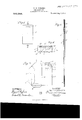
- FIG. 1 is a face view thereof
- Fig. 2 is a longitudinal sectional view taken on the line 2 2 of Fig. 1 and looking in the direction indicated by the arrows
- Fig. 3 is a developed View of the blank of which the envelop is constructed
- Fig. 4 is a view showing a part of a part-ly completed container.
- rl ⁇ he envelop comprises the front wall 5 and the rear wall 6, the front .wall being provided with va slot 7 of such size as to admit of the passage of the largest size coin to be accommodated.
- the back wall 6 is provided with the flaps 8, 8which are turned back, as shown in dotted-lines in Fig. 3.
- the wall 5 is provided at the top with a flap 9 which is preferably a symmetrical reproduction of the top flap 8 on the back wall 6, and this flap is turned back as indicated in dotted lines.
- the flap 9 is provided with a U-shaped cut 10 so as to form a tongue 11 which may be turned downwardly, as shown in the drawings so that the resulting opening 12 may register with the slot 7.
- Glue is disposed upon the face of the tongue 11, as exposed in Fig. 3, and when the flap 9 is turned down this tongue will adhere firmly to the front wall 5, as clearly shown in Fig. 2. This forms an effective guard for the slot 7 and it prevents any coin from entering between the flap 9 and the wall 5 anywhere near this slot.
- the device which I provide is simple and inexpensive and its destruction is necessary if the coins are to be removed therefrom.
- a coin receptacle in the form of an envelop having at its top two inturned flaps secured together, one of said flaps cut to form a tongue and a resulting opening, the wall from which said flap extends having a registering opening, and said tongue being folded down between said flap and said last-named wall below the openings therein.
Landscapes
- Engineering & Computer Science (AREA)
- Mechanical Engineering (AREA)
- Purses, Travelling Bags, Baskets, Or Suitcases (AREA)
Description
11... m w U 1, oo 6 Fm.. E 2.9 DW E m n n d 9 EH F Lw M f W f V m U onu 7 n. f ,.m E .fu 7 H.. A n 7i u j W i VL n ru m f 4 s, 7 w f J W, 0 H m W m n n m Hmmm 7 5 1 n ,f W w m y /v ,SO M n A AV 5 8W E l 8 EN w 2, E .9 Wy
WILLIAM H. WOOLUMS,
GF CHICAGO, ILLINOIS.
FFIQF.,
COIN-RECEPTACLE.
Specification of Letters Patent.
Patented Aue". 1, 1911.
Application filed February 13, 1911. Serial No. 608,205.
To all whom it may concern:
Be it known that I, VILLIAM H. WOOL- UMS, a citizen of the United States, residing at Chicago, in the county of Cook and Siate of Illinois, have invented a certain new and useful Improvement in Coin-Receptacles, of which the following is a full, clear, concise/and exact description, reference being had to the accompanying drawings, forming a part of this specification.
My invention relates to coin receptacles, tuch as are adapted to be carried about ones person, which are so constructed that, while coins may be readily deposited therein, they cannot be removed therefrom wit-hout destroying the receptacle. In order that the destruction of these pocket banks, as they are sometimes called, when it is desired to remove the contents thereof, may be part of a practicable plan, such as a publicity plan for the purpose of encouraging the opening of new accounts vwith some commercial banking institution, the receptacle or bank is made of some inexpensive material such as cardboard, heavy paper, or leatherette. The device is quite in the form of an envelop and is provided with an opening through which the coins may be introduced and with which certain means is associated for preventing the extraction of coins in any ordinary manner.
The object of my invention is to provide such a container with improved means for permitting admission but preventing extraction of coins.
My invention is embodied in the device illustrated in the accompanying drawing, in which- Figure 1 is a face view thereof; Fig. 2 is a longitudinal sectional view taken on the line 2 2 of Fig. 1 and looking in the direction indicated by the arrows; Fig. 3 is a developed View of the blank of which the envelop is constructed; and Fig. 4 is a view showing a part of a part-ly completed container.
Like reference characters are applied to the same parts throughout the various tlgures.
rl`he envelop comprises the front wall 5 and the rear wall 6, the front .wall being provided with va slot 7 of such size as to admit of the passage of the largest size coin to be accommodated. The back wall 6 is provided with the flaps 8, 8which are turned back, as shown in dotted-lines in Fig. 3.
The wall 5 is provided at the top with a flap 9 which is preferably a symmetrical reproduction of the top flap 8 on the back wall 6, and this flap is turned back as indicated in dotted lines. The flap 9 is provided with a U-shaped cut 10 so as to form a tongue 11 which may be turned downwardly, as shown in the drawings so that the resulting opening 12 may register with the slot 7. Glue is disposed upon the face of the tongue 11, as exposed in Fig. 3, and when the flap 9 is turned down this tongue will adhere firmly to the front wall 5, as clearly shown in Fig. 2. This forms an effective guard for the slot 7 and it prevents any coin from entering between the flap 9 and the wall 5 anywhere near this slot. After all the flaps have been turned down as illustrated in dotted lines in Fig. 3, glue is disposed upon the faces thereof, as indicated at 13, 13 in Fig. 4. The wall 5 is then folded over on the line 14 so that the flap 9 may adhere to the corresponding flap 8 and so that the other aps 8, 8 may adhere directly to the wall. It is to be noted that the flaps 8 and 9 are glued together only above and at the sides of the opening 12 and it is thus apparent that coins may be forced through the slot 7 down between the flaps 8 and 9 and into the receptacle. It is very unlikely that any coins should ind their .way back between the flaps 8 and 9 and, if they do, it will be diflicult for them to find an exit through the slot 7 because the slot is at the side and it would be impossible for the coin to make such a short turn. Coins falling between flaps 8 and wall 6 .will tend to cause flap 8 to close the hole.
The device which I provide is simple and inexpensive and its destruction is necessary if the coins are to be removed therefrom.
I claim as new and desire to secure by Letters Patent:
1. A coin receptacle in the form of an envelop having at its top two inturned flaps secured together, one of said flaps cut to form a tongue and a resulting opening, the wall from which said flap extends having a registering opening, and said tongue being folded down between said flap and said last-named wall below the openings therein.
2. A coin receptacle in the form of an envelop having two inturned flaps, one of said flaps having a U-cut to form a tongue and a resulting opening, there being an opening n the Wall from Which said 1ast-na1ned In Wit-ness whereof, I hereunto subscribe flap extends registering With said rstmy name this 9th day of February, A. D. named opening, said tongue being folded 1911.
down and secured to said Wall below the VILLIAM H. WOOLUMS. 5 opening therein and said flaps being se- Witnesses:
cured together above said first-named open- ARTHUR H. BOETTCHRR,
ing and at the sides thereof. ALBERT G. MCCALEB.
Copies of this patent may be obtained forve cents each, by addressing the Commissioner of Patents,
Washington, D. C.
Priority Applications (1)
| Application Number | Priority Date | Filing Date | Title |
|---|---|---|---|
| US60820511A US999288A (en) | 1911-02-13 | 1911-02-13 | Coin-receptacle. |
Applications Claiming Priority (1)
| Application Number | Priority Date | Filing Date | Title |
|---|---|---|---|
| US60820511A US999288A (en) | 1911-02-13 | 1911-02-13 | Coin-receptacle. |
Publications (1)
| Publication Number | Publication Date |
|---|---|
| US999288A true US999288A (en) | 1911-08-01 |
Family
ID=3067616
Family Applications (1)
| Application Number | Title | Priority Date | Filing Date |
|---|---|---|---|
| US60820511A Expired - Lifetime US999288A (en) | 1911-02-13 | 1911-02-13 | Coin-receptacle. |
Country Status (1)
| Country | Link |
|---|---|
| US (1) | US999288A (en) |
-
1911
- 1911-02-13 US US60820511A patent/US999288A/en not_active Expired - Lifetime
Similar Documents
| Publication | Publication Date | Title |
|---|---|---|
| US460472A (en) | Envelope book | |
| US464728A (en) | Coin-mailing card | |
| US1173843A (en) | Ticket-holder. | |
| US911794A (en) | Record-packet. | |
| US1359319A (en) | Collector's book-cover and wallet | |
| US999288A (en) | Coin-receptacle. | |
| US1315696A (en) | Mailhsra-pttbse | |
| US2855138A (en) | Bank deposit envelopes | |
| US505001A (en) | Martin ralph | |
| AU603777B2 (en) | Improvements in or relating to bags | |
| US854069A (en) | Credit-account-filing system. | |
| US2623632A (en) | Money packet | |
| US1152937A (en) | Coin-receptacle. | |
| US877951A (en) | Coin-receptacle. | |
| US2927803A (en) | School bank book | |
| US1871774A (en) | Advertising folder | |
| US1005403A (en) | Filing-case. | |
| US933754A (en) | Means for encouraging and facilitating the accumulation of savings. | |
| US1213748A (en) | Mailing-card. | |
| US1028888A (en) | Package of commodity. | |
| US517175A (en) | Nathan a | |
| US709656A (en) | Coin-case. | |
| US856390A (en) | Envelop. | |
| US1331947A (en) | Check | |
| US1082702A (en) | Voucher-check. |