US998894A - Stencil-machine character-punch. - Google Patents
Stencil-machine character-punch. Download PDFInfo
- Publication number
- US998894A US998894A US1910576158A US998894A US 998894 A US998894 A US 998894A US 1910576158 A US1910576158 A US 1910576158A US 998894 A US998894 A US 998894A
- Authority
- US
- United States
- Prior art keywords
- punch
- stencil
- bur
- plug
- machine character
- Prior art date
- Legal status (The legal status is an assumption and is not a legal conclusion. Google has not performed a legal analysis and makes no representation as to the accuracy of the status listed.)
- Expired - Lifetime
Links
- 238000005520 cutting process Methods 0.000 description 8
- 238000010276 construction Methods 0.000 description 4
- 239000000463 material Substances 0.000 description 2
- 238000000034 method Methods 0.000 description 2
- 230000015572 biosynthetic process Effects 0.000 description 1
- 230000007547 defect Effects 0.000 description 1
- OYFJQPXVCSSHAI-QFPUQLAESA-N enalapril maleate Chemical group OC(=O)\C=C/C(O)=O.C([C@@H](C(=O)OCC)N[C@@H](C)C(=O)N1[C@@H](CCC1)C(O)=O)CC1=CC=CC=C1 OYFJQPXVCSSHAI-QFPUQLAESA-N 0.000 description 1
- 230000001788 irregular Effects 0.000 description 1
- 238000004519 manufacturing process Methods 0.000 description 1
- 239000002184 metal Substances 0.000 description 1
- 238000004080 punching Methods 0.000 description 1
- 229910000679 solder Inorganic materials 0.000 description 1
Images
Classifications
-
- B—PERFORMING OPERATIONS; TRANSPORTING
- B21—MECHANICAL METAL-WORKING WITHOUT ESSENTIALLY REMOVING MATERIAL; PUNCHING METAL
- B21D—WORKING OR PROCESSING OF SHEET METAL OR METAL TUBES, RODS OR PROFILES WITHOUT ESSENTIALLY REMOVING MATERIAL; PUNCHING METAL
- B21D28/00—Shaping by press-cutting; Perforating
- B21D28/24—Perforating, i.e. punching holes
- B21D28/34—Perforating tools; Die holders
-
- Y—GENERAL TAGGING OF NEW TECHNOLOGICAL DEVELOPMENTS; GENERAL TAGGING OF CROSS-SECTIONAL TECHNOLOGIES SPANNING OVER SEVERAL SECTIONS OF THE IPC; TECHNICAL SUBJECTS COVERED BY FORMER USPC CROSS-REFERENCE ART COLLECTIONS [XRACs] AND DIGESTS
- Y10—TECHNICAL SUBJECTS COVERED BY FORMER USPC
- Y10T—TECHNICAL SUBJECTS COVERED BY FORMER US CLASSIFICATION
- Y10T83/00—Cutting
- Y10T83/929—Tool or tool with support
- Y10T83/9411—Cutting couple type
- Y10T83/9423—Punching tool
- Y10T83/9428—Shear-type male tool
- Y10T83/9432—Plural spaced successively operative shearing portions
Definitions
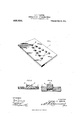
- FIG. 1 is a perspective view of a stencil machine character punch of my improved construction.
- Fig. 2 is an enlarged sectional view taken on the line 22 of Fig. 1.
- Fig. 3 is a sectional view similar to Fig. 2, and showing a modified construction of the characte punch.
- My i vention relates to a stencil machine character punch of the type wherein the punch plate carries one or more portions punched from another plate. and which punched portions are seated in the punch plate so that the bur formed on the upper edge of the punched-out portions during the punching-out operation forms the cutting edge of the finished punch plate.
- Stencil machine character punches of my improved construction are interchangeable, can readily be applied to or removed from nearly all types of stencil machines now in general use, and by reason of the peculiar formation of the marginal edges of the projecting portions of the punches, the same will produce a clean well defined cut in service.
- a character punch for stencil machines comprising in combination a base plate in which is formed a series of openings so arranged as to form the outline of a character, punched out plugs of the same size and shape as said openings, which plugs are seated in the openings with portions projecting a substantial distance from the face of the plate, which plugs are rigidly fixed to the plate in the openings thereof, a continuous bur formed on the marginal edge of each plug and which bur is substantially V- shaped in cross section and projects beyond the face of the plug.
- a stencil machine character punch comprising a base plate in which is formed a series of openings, punched out plugs of ductile material of the same size and shape as said openings, which plugs are seated in said openings and rigidly fixed to the base plate with uniform portions projecting from one of the faces of the base plate, a continuous minute bur on the marginal edge of each plug and which bur is substantially V- shaped in cross section and projects beyond the face of the plug.
Landscapes
- Engineering & Computer Science (AREA)
- Mechanical Engineering (AREA)
- Manufacture Or Reproduction Of Printing Formes (AREA)
Description
UNITED T FFliQE.
STEPHEN D. I-IARTOG, OF ST. LOUIS, MISSGUBI, ASSIGNOR '10 THE DIAGRAPH COIVIPANY, OF ST. LOUIS, MISSOURI, A CGBPORATION OF MISSOURI.
STENCIL-MACHINE CHARACTER-PUNCH.
To all whom it may concern:
Be it known that l, STEPHEN D. HAnToo, a citizen of the United States, residing at St. Louis issruiri, have invented a certain new and useful improvement in Stencil-Machine Character-Punches, of which the following is a full. clear, and exact description, such as will enable other-s skilled in the art to which it appertains to make and use the same, reference being had to the accompanying drawings, forming part of this specification, in which Figure 1 is a perspective view of a stencil machine character punch of my improved construction. Fig. 2 is an enlarged sectional view taken on the line 22 of Fig. 1. Fig. 3 is a sectional view similar to Fig. 2, and showing a modified construction of the characte punch.
My i vention relates to a stencil machine character punch of the type wherein the punch plate carries one or more portions punched from another plate. and which punched portions are seated in the punch plate so that the bur formed on the upper edge of the punched-out portions during the punching-out operation forms the cutting edge of the finished punch plate.
While punches of my improved construc tion can be formed in any suitable and convenient manner, I prefer to form them in accordance with the method described in a copending application filled by me is pril 26, 1910, Serial No. 557,635, and of which the present application is a division.
In stencil machine character punches it is essential that the cutting edges be sharp and well defined, and if said edges are rounded off in the process of making, it is necessary to grind off the faces of the projecting portions of the punch plate before the same is hardened, in order to secure the desired sharp, clean cutting edges. This grinding operation, besides involving considerable time and labor, does not always remedy the defects, inasmuch, as the projecting portions of stencil machine character punches are of irregular outline and it is practically a physical impossibility to evenly grind the faces of said projecting portions. I propose to overcome the objections above noted by producing a punch wherein the projecting portions are located on the base plate with the continuous, minute, knife-edged Specification of Letters Patent.
Original application filed April 26, 1910,-Seria1 110. 557,835.
Patented July 25, 191i.
Divided and this application filed August 8,
Serial No. 576,158.
burs on the outer edge of said projecting portions, and when the so formed punch is hardened these burs form a most desirable and efficient cutting edge for said punch.
One of the principal objects of my invention is to produce interchangeable punch plates which are complete and ready for use in connection with the types of stencil cutting machines now in general use.
To the above purposes, my invention consists in the features of novelty hereinafter more fully described and claimed.
Referring by numerals to the accompanying drawings 1 designates the base plate forming the body of the punch, and rigidly fixed therein or thereto is one or more projecting members 2, which, when the punch is in use, enter and pass through corresponding openings formed in the punch plate. lVhen the members 2 are punched from a plate the metal which is necessarily ductile draws out around the edges of each member immediately adjacent the punching tool, thereby forming a continuous integral minute bur 3 on one edge of each member, which bur extends slightly beyond the face of the member and the body of said bur is approximately wedge-shape in cross section. After the punch is hardened, the bur forms a sharply defined cutting edge, which is very effective when the punch is in use and the projecting portions 2 enter the openings in the punch plate.
As shown in Fig. 2, the plug or portion 2 provided with the bur 3 is approximately twice as thick as the base plate 1, and as the rear face of the plug or portion 2 lies flush with the rear face of said base plate, a substantial portion, or approximately half of said plug or portion 2 projects beyond the front face of the base plate.
In Fig. 3, the plug or portion 3 is shown seated in a base plate having a thickness approximately equal to that of the plug or portion 3, and when a punch is so constructed, the space in the base plate behind the plug or portion 2 is filled with solder or the like.
As hereinbefore stated the minute bur on the edge of the projecting portion of the punch forms a sharp, well defined cutting edge, which cooperates with the corresponding edge of the opening in the punch plate to bring about the much desired clean shear out through the material in which the stencil is formed.
l/Vhere stencil machine character punches are formed in accordance with my invention, it is not necessary before first applying the punches to the stencil machine to resort to the grinding-elf operations required to sharpen the cutting edges of punches formed without the bur, and which grinding-off operation involves considerable time and labor.
Stencil machine character punches of my improved construction are interchangeable, can readily be applied to or removed from nearly all types of stencil machines now in general use, and by reason of the peculiar formation of the marginal edges of the projecting portions of the punches, the same will produce a clean well defined cut in service.
I claim:
1. In a stencil machine character punch, the combination with a base plate in which is formed an opening, of a punched out plug of the same size and shape as said opening, which plug is rigidly seated in said opening with a substantial portion projecting from the face thereof and a continuous bur formed on the marginal edge of the plug and which bur is substantially V- shaped in cross section and projects beyond the face of the plug.
2. A character punch for stencil machines comprising in combination a base plate in which is formed a series of openings so arranged as to form the outline of a character, punched out plugs of the same size and shape as said openings, which plugs are seated in the openings with portions projecting a substantial distance from the face of the plate, which plugs are rigidly fixed to the plate in the openings thereof, a continuous bur formed on the marginal edge of each plug and which bur is substantially V- shaped in cross section and projects beyond the face of the plug.
3. As a new article of manufacture, a stencil machine character punch, comprising a base plate in which is formed a series of openings, punched out plugs of ductile material of the same size and shape as said openings, which plugs are seated in said openings and rigidly fixed to the base plate with uniform portions projecting from one of the faces of the base plate, a continuous minute bur on the marginal edge of each plug and which bur is substantially V- shaped in cross section and projects beyond the face of the plug.
In testimony whereof I hereunto affix my signature in the presence of two witnesses,
this 6th day of August, 1910.
STEPHEN D. HARTOG. Witnesses:
M. P. SMITH, B. L. CROWLEY.
Copies of this patent may be obtained for five cents; each, by addressing the Commissioner of Patents, Washington. D. C.
hwmvw
Priority Applications (1)
| Application Number | Priority Date | Filing Date | Title |
|---|---|---|---|
| US1910576158 US998894A (en) | 1910-04-26 | 1910-08-08 | Stencil-machine character-punch. |
Applications Claiming Priority (2)
| Application Number | Priority Date | Filing Date | Title |
|---|---|---|---|
| US1910557635 US994463A (en) | 1910-04-26 | 1910-04-26 | Method of making stencil-machine character-punches. |
| US1910576158 US998894A (en) | 1910-04-26 | 1910-08-08 | Stencil-machine character-punch. |
Publications (1)
| Publication Number | Publication Date |
|---|---|
| US998894A true US998894A (en) | 1911-07-25 |
Family
ID=3067221
Family Applications (1)
| Application Number | Title | Priority Date | Filing Date |
|---|---|---|---|
| US1910576158 Expired - Lifetime US998894A (en) | 1910-04-26 | 1910-08-08 | Stencil-machine character-punch. |
Country Status (1)
| Country | Link |
|---|---|
| US (1) | US998894A (en) |
-
1910
- 1910-08-08 US US1910576158 patent/US998894A/en not_active Expired - Lifetime
Similar Documents
| Publication | Publication Date | Title |
|---|---|---|
| US2029567A (en) | Method of making embossing dies | |
| US1325194A (en) | of belleville | |
| US3566513A (en) | Metal punching | |
| US998894A (en) | Stencil-machine character-punch. | |
| US335334A (en) | Method of making dies | |
| US2056321A (en) | Die and method of making the same | |
| US354412A (en) | Making perforated screening-plates | |
| US3052139A (en) | Method of making steel rule blanking die | |
| US3145586A (en) | Process for making a tungsten carbide die | |
| US1499309A (en) | Punching tool and method of making same | |
| US1701545A (en) | Blanking die and method of making the same | |
| US1566624A (en) | Method of forming double-cut pipe | |
| JPH02280926A (en) | Punching method for preventing shear droop and burrs | |
| JPS59144588A (en) | Manufacture of laminated die by laser working | |
| US598867A (en) | Stephen d | |
| US3020785A (en) | Dual steel rule blanking die and method of making it | |
| US991498A (en) | Method of making stencil-machine character-punches. | |
| US1782518A (en) | Screen pipe and method of making same | |
| US891516A (en) | Metal-punch. | |
| US2699211A (en) | Perforating machine | |
| US3714807A (en) | Process of making a cutter foil for dry shaving apparatus | |
| US965855A (en) | Method of narrowing slits punched in plates of hard metal. | |
| US370985A (en) | stimpsof | |
| US1334149A (en) | Method oe producing punchings | |
| US3459090A (en) | Clicking die for cutting sheet materials and method of making said die |