US998765A - Range-finder. - Google Patents
Range-finder. Download PDFInfo
- Publication number
- US998765A US998765A US5716?710A US998765DA US998765A US 998765 A US998765 A US 998765A US 998765D A US998765D A US 998765DA US 998765 A US998765 A US 998765A
- Authority
- US
- United States
- Prior art keywords
- telescope
- axis
- support
- telescopes
- instrument
- Prior art date
- Legal status (The legal status is an assumption and is not a legal conclusion. Google has not performed a legal analysis and makes no representation as to the accuracy of the status listed.)
- Expired - Lifetime
Links
Images


Classifications
-
- G—PHYSICS
- G01—MEASURING; TESTING
- G01C—MEASURING DISTANCES, LEVELS OR BEARINGS; SURVEYING; NAVIGATION; GYROSCOPIC INSTRUMENTS; PHOTOGRAMMETRY OR VIDEOGRAMMETRY
- G01C1/00—Measuring angles
Definitions
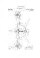
- Figure 1 of the drawings is a top plan view of theinfstrument, with certain portions broken away for convenience of illus tra'tion.
- Fig. 2 is a view in side cle ation of the same, seen from the left of Fig. 1.
- Fig. 3 is a vertical longitudinal section showing the manner in which an tension-plate for an auxiliary telescope is detachably mounted.
- Fig. 4 is a view in front elevation of the instrument as seen in Fig. 1.
- Fig.5 is a View in elevation of the instrument viewed from the side opposite that of Fig. 2 the nearer auxiliary teles ipe being omitted.
- Fig. 6 is a bottom'plan view of a brolteiraway portion of an extensionplate for an anx'iliary' telescope.
- Fig. 7 is 'a view in rear elevation of the instrument,
- Fig.9 is a diagrammatic view illustrating one method of determining. distances by the use'ot' the instrument.
- Fig. 10 is a central vertical section of the instrument.
- the principal object of the invention is to dcterminefrom points. of observation Within a: portable instrument the distance of "various objects and the measurement of vertical andhorizontalangles and 'gradients at a distance from the instrument; also to pro- Similar characters refer to be compared with and corrected by another to insure accuracy.
- 1. is the upper member and, Q, the lower member of a stand mounted upon a folding-tripod 3.
- the parts, 1 and 2 are screwed together as shown.
- the upper .inemhcr, I. of the stand is centrally apertured to receive a stud, 4, the upper end of which is screw-threaded and has tightly fixed thereon a bearing yoke Interposed between the bearing-yoke, 5,
- the member, 1, of the stand is a friction- (llSh', (3, and a Vernier-disk, 7, each apertured. to receive the stud at. Upward movement of the stud. 4. is limited by the head of a screw, 8, inserted in the lower end of the stud.
- 'llhumb-screws, 9, are inserted in screwthreadcd apertures in a peripheral flange, 10, on the standanember, l, with their upper ends adapted to abut upon the underside of the friction-disk, 6. to force said disk and the Vernier-disk, 7, upward against the l'iearing-yoke, 5, to hold said yoke against rotative movement.
- One or more of the thumb-screws, 9, occupies a seat or recess,
- the Vernier-disk, 7, can he rotated relatively to the friction-disk, 6,3136; then locked by means of the thumb-screw, 13, in a selected rotary position.
- the vernier-disk, 7, can thus be set to'indieat-e zero,
- a cross-shaft, 15, is mounted in the bearing-yoke, 5, at right angles to the axial line vide in the-one portableinstrument a pluof the stud 4.
- a post, 16',' is mounted upon rality of means for making the required the shaft, 15, to turn thereon, said postsupmeasurements whereby one set of resultsscan porting a box comprising a bottom-plate, 17,
- a worm-gear, 26 Fixed upon the lower end of the stud, 24, is a worm-gear, 26, adapted to be engaged by a worm, 27, fixed upon a worm-shaft, 28, which projects outthrough an aperture in the cylindrical wall, 20, upon which wall is fixed a bearing for the worm-shaft, 28, said shaft being provided on its outer end with a small hand-wheel, 30, whereby a gradual rotative movement can be imparted to the 2".
- 2G, stud, 24, and Vernier-segment 23 The Vernier-segment has mounted thereon an index-plate, 31, graduated to be read in connection with graduations on the vernierfiange 19.
- a telescope, 33 is rotatively mounted upon the Vernier-segment, 23, to turn thereon upon an axis perpendicular to the plane of the Vernier-segment, and coincident with the center of the circle of which said Verniersegment forms a part, and parallel with, and some distance in rear of, the axis of the stud 24.
- the frame, 3-4 by means of which the telescope, is thus mounted, is formed to overhang a graduated scale arranged along the are formed by the circular edge of the segment, which frame carries an index-plate, 35,-graduated to be read in connection with said graduations on the segment, and also carries a wire, 36, adapted to serve an index for reading the graduations on said segment.
- the front end of said frame, 34 has a depending-lug, 37, located just outside the periphery of the segment, through an aperture in which lug a set-screw, 3 8,"is inserted adapted to be set into engagement with the peripheral edge of the vernier-segment to lock the telescope, 33, and its supporting-frame at any desired point.
- lhetelescope, 33 has mounted thereon parallel with its axis, a spirit-level, 40; and the frame which supports said telescope has mounted thereon a similar spirit-level, 3D," in a position at right angles to that ofthc parallel with, the straight level, 40, both of said 7 levels occupyirg planes parallel withthe plane of the ver- I niersegment 23.
- the verm(er-segment also has mounted thereon a magnetic compass,
- a plate, 41 is rotat-ively mounted upon the Vernier-segment at the rear thereof to turn upon an axis substantially in the plane of said segment, andv just in rear of. and
- said plate being so mounted by means of setscrews, 42, passing through and adapted to frictionally clamp together brackets, 43 and 44, mounted, respectively, upon said segment and said plate, whereby said plate can be rocked through approximately 180 degrees, and clamped in any selected position in its path of movement, said plate in its extreme positions having its surface substantially parallel with the Vernier-segment 23.
- a pair of telescopes, 45 equidistant from the middle radial line ofl'he vcrniersegment, and from the axis of rotary movement of the telescope 33.
- each of the telescopes, 45 is preferably mounted upon the plate, 41, by means of an extension-plate, 46, having a.
- each of said extension-plates with its telescope, 45 can be detached and separately packed.
- Each of the telescopes, 45 is mounted to rotate upon an axis, 53, perpendicular to the plane of the extension-plate, 46, and has fixed thereto to rotate therewith a Verniersegmcnt, 54, the graduations on which are adapted to be read with relation to either of the index-plates, 55, extension-plate 46.
- a gradual rotative movement of the telescope, 45, upon said axis, 53, can be accomplished by means of i a. worm-gear, 56, in fixed relation to the telescope, 45, and adapted to be engaged by a worm, 57, on a worm-shaft, 58, adapted to be operated by means of a small. handwheel 59.
- Each of the telescopes, 45,15 also adapted to rock upon an axis, 60, by means of trunnions on said telescope, which are adapted to be clamped in any selected position within the split-bearing, 61', by means of a hand-operated. set-screw 62.
- Each of said telescopes, 45 has fixed upon mounted on the one of its trunnions an arm 63, carrying an" index'plate,” 64, adapted to traverse the Vernier-segment, 65, and having graduations adapted to he read in connection with graduations on said Vernier-segment.
- a comparativelydarge telescope, 67 having an extension eye-piece, 68; and mounted adjacent thereto and parallel therewith is a spirit-level 69.
- the telescope, 33 has a pointer or needle, 70, depending therefrom somewhat in rear of its axis oi rotation, which needle is adapted to traverse an arc, 71, on the surface of the plate, 11, and the movement of said .sonable accuracy.
- the instrument above described is practically universal in its capability of adjustment, and can be adjusted to measure angles in practically any plane, horizontal, vertical or oblique, having within the instrument itself a base-line of knownlength extending from axis to axis, 53, of the telescopes 45.
- Fig. 9 of the drawings is illustrated by means of a diagram one manner of quickly computing the range or distance of an object by means of the above described instrument.
- the telescope, 33, and one of the telescopes, 4-5 are both brought to bear upon the distant obj not, with the telescope, 45, at right angles to the baseline of the instrument.
- C is the distant object;
- A is the axis upon which the telescope, 33, rotates, and
- B is the point where the line of sight of the telescope, 45, is intersected by a line, A B, perpendicular thereto, extending from the axis upon which the telescope, 33, rotates, which line, A B, is the base-line.
- Two similar rightongled triangles are thus formed, one, A B C, of which only the side,
- a B is known, and the other, A E F,-oi" which, A. E, is known being the radius of the arc traversed by the needle, 70, and, A F, is known, being the distance from the center, A, of the cord-line, 72, which intersects the arc, 71, at the point, F.
- the lines, 7 2 being equidistant from one another, and running twenty or even more to the inch, make it possible to quickly determine by observation the length of, 'A F, with ma A E,
- a E F can be and with the three sides of the triangle, -A E F, known,
- the value of the lines of the scale, 77 may be numerically indicated on the surface of'tho vernier-segment, 23, if desired.
- the post, 16, and parts carried thereby can be rocked upon the shaft, 15, by means of a gearsegment, 83, fixed to the plate, 17, and adapted to be engaged by a pinion, S0, fixed upon a short shaft rotalii ely mounted in hearings in the yoke, 5, and a b *ackci, 352, at tached to the yoke, said sha'lt having an operating handle 81.
- the post, lb, 7 can be locked in adjusted rotative position by means oi thcnut, 86,"whicl1 [its a screwthroaded. end of the shaft 15.
- the inoyemcnt oi the frame, 34- may be facilitated by mounting the same upon small rollers, 38, adapted toiravcl upon the upper surface of the Vernier-segment 23,
- the instrumcnt may also be provided, if desired, with a. plumb 1197.
- the rernicr-segment, 23 can be rotated to bring the telescope, 67,:1t right angles to the crossshaft, 15, whereupon the altitude can be read upon the Vernier-scale, 84:, by means of the index, 85, while the azimuth can be read upon the Vernier-disk, 7, by means of the index-plate 12.
- the extension-plates, 4-6, vvith the auxiliary' telescope fixed thereon, respectively can be removed and the plate, 41, can be swung back and (lOWll out of the way to permit unrestricted use of the telescope 33.
- a support rotatory upon a horizontal axis; a head mounted upon said support and rotatory upon an axis at right angles to the axis of rotation of said support; a pair of telescopes mounted upon said rotatory head, and each rotatory upon a vertical axis; a third telescope mounted upon said 'rotatory head; and graduated scales for' measuring the angular movement of each of said pair of telescopes.
- a support rotatory upon a horizontal. axis; a head mounted upon said support and rotatory upon an axis at right angles tothe axis of rotation of said support; a pair of telescopes mounted upon said rotatory head, and each rotatory upon an axis parallel with the ax'is pf rotation of said head: a third telescope mounted upon said rotatory head, and independently rota-.
- a support rotatively mounted upon said support: a telescope rotatively mounted upon said head; an auxiliary telescope-support hinged upon said head on an axis at right anglesto the axis of rotation of said telescope; a pair of telescopes rotatively mounted upon said auxiliary telescope support; scales for measuring the angular movement of said telescopes.
- a supporting-head rotatory upon a vertical axis; a telescope rotatively mounted upon said head; an auxiliary telescope-support hinged upon said ro tatory head on an axis at right angles to the axis of said telescope; a pair of telescopes each rotatively mounted upon said auxiliary telescope-support; and graduated scales for measuring the angular movement of said telescopes.
- a supporting-head rotatory upon a vertical axis; a telescope rotatively mounted upon said head; an auxiliary telescopesupport rotatively mounted upon said head; a pair of extension-plates -'projecting in opposite directions from said support, and each detachably connected therewith; a pair of telescopes rotatively mounted upon said extension-plates, respectively; and graduated scales for measuring the angular movement of said telescopes.
- a supporting-head rotatory upon tvvo axes at right angles to each other a telescope rotatively mounted upon said head; an auxiliary telescope-support hinged upon said rotatory head, and having along one of its sides a straight edge; a pair of telescopes each rotatively mounted upon said auxiliary telescope-support;1and graduated scales for measuring the angular movement of said telescopes.
- a lower supportingmember an upper.supporting-member rotatively mounted upon said lower support ing-member on a vertical axis; adjustable means for locking said members together against relative rotation; a Vernier-plate adjustably. mounted upjon one'of said members to be read in connection with an index on the other; a support rotatively mounted upon a. horizontal axis upon said ,upper supand graduated' porting-member; and a telescope mounted" upon said support.
- a lower supporting-member In an instrument of the class described, and in combination, a lower supporting-member; an upper supportingmember rotatively mounted upon said lower supporting-member on'a vertical axis; adjustable means for locking said members together against relative rotation; a Vernierplate adjustably mounted upon one of said members to be read in connection With an index on the other; a support rotatively mounted upon a horizontal axis upon said upper supporting-memberya pair of telescopes mountcd upon said-support, each rotatory upon an axis at right angles to the axis of said support; and graduated scales for measuring the angular movement of said last-mentioned telescopes.
- a lower supportii'ig-men'iber an upper supporting member.rotatively mounted upon said lower supportingancmber on a vertical axis; adjustable means for locking said members together against relative rotation; a Vernierplate adjustably mou ted upon one of said members to be read i1 connection with an index on the other; a support rotatively mounted upon a horizontal axis upon said upper supporting-mcmber; a pair of telescopes mounted upon said support, each rotatory upon an axis at right angles to the axis of said support; a third telescope mounted upon said support and independently rotatory upon an axis at right angles to the axis of said support; and graduated scales for measuring the angularmovement of said'telescopes.
- a lower supportingmcmber an upper supporting-member rotatively mounted upon said lower support ing-member on a vertical axis; adjust-able means for locking said members together against relative rotation; a Vernier-plate adjustably mounted upon one of said members i to be read in connection with an index on the other; a support rotatively mounted upon a horizontal axis upon said upper supporting member; a vermersegment rotatively mounted upon said support on an axis at right angles to the axis thereof; and a telescope rotalively mounted upon said vernier-scgm'ent on an axis at right angles to the axis'of said support.
- a lower supportingmember an upper supporting-member rota,- tively mounted upon said lower supportingmcmber on a vertical axis; adjustable means for locking said members togetherv against relative rotation; a Vernier-plate adplstably mounted upon one of said members to be read in connection with an indexon theother; a support rotatively mounted upon a horizontal axis upon said upper supportingmember; a Vernier-segment rotatively mounted upon said support on an axis at right angles to the axis thereof; a telescope'rotatively mounted upon said Vernier-segment on an axis at right angles to the axis of said support; and a pair of auxiliary telescopes each r'otatively mounted upon said Verniersegment.
- a support in combination, a support; three telescopes rotatively mounted upon parallel. axes upon said support; means for'rotatively supporting said support with capability for rotative movement upon two axes at right angles to each other; and graduated scales fo measuring the angular movement of said telescopes.
- a support in combination, a support; three tblescopes rotat-ively mounted upon parallel axes upon said support; means for rotatively supporting said support with capability for rotative movement upon three axes, two of which are at right angles to the third; and graduated scales for measuring the angular movement of said telescopes.
- a support for measuring distances, and in combination, a support; a telescope rotatively mounted upon said support; another telescope mounted u on said support; means for holding said do ier telescope in fixed relation to said support at right angles to a line extending from one to the other of said telescopes; and a pointer carried by said rotatively mounted telescope, said support having parallel graduationlines at right angles to the axis of said second mentioned telescope, and forming chords to the are traversed by said pointer.
Description
J. FOLEY, DEGD.
L1). POL'EY, ADMINISTRATOR.
RANGE FINDER.
APPLICATION FILED JULY 13, 1910.
6 SHEETS-SHEET 1.
Q; a\ Li w I [II II" {Q mllll, a
Patented July 25, 1911.
J. FOLEY, DBGD. J. D. FOLEY, ADMINISTRATOR.
RANGE FINDER.
APPLICATION rum) JULY 13, 1910.
998,?65, Patented July 25,1911.
6 8HEETB-SHEET 2.
\A/iTNlEfiEEJ fig. 6. N- ,fi 'az,
J. FOLEY, DEGD.
J. D. FOLEY, ADMINISTRATOR. RANGE FINDER.
APPLICATION FILED JULY 13, 1910.
9 983 765 Patented July 25, 1911.
6 SHEETS-SHEET 3.
J. FOLEY, DEGD. J. n. FOLEY, ADMINISTRATOR.
RANGE FINDER. APPLICATION FILED JULY 13, 1910.
Patented July 25, 1911.
6 SHEETS-SHEIJT 1.
J. FOLEY, 1150 11. J. D. FOLEY, ADMINISTRATOR.
RANGE FINDER.
APPLICATION FILED JULY 13, 11110.
998,765. Patented July 25, 1911 6 SHEETS-SHEET 5.
A/l TNEESES J. FOLEY, DBCD.
J. D. FOLEY, mmms'rmrox.
RANGE FINDER.
APPLICATION TILED JULY 13, 1910.
998,765 Patented July 25, 1911.,
6 SHEETS-SHEET 6.
entrain s'ra'rns ra'irnnr enrich.
JOHN FOLEY EECEASED, LATE OF NAAS, IRELAND, BY JOSEPH D. FOLEY, ADMINIS- TRATOR, OF TROY, NEW YORK.
RANGE-FINDER.
Specification of Letters Patent.
Patent-ed July 25, 1911.
Application filed July 13, 1910. Serial No. 571.687.
To all whom it may concern.
Be it known that Jonn FoLnr, late a ,citizen of Great Britain, residing atthe town of Naas, countyot' Kildare, Ireland, did invent new and useful Improvements in ltange-l inders, of which the following is a specification. 1
The invention relates to such improvements and consists of the novel construction I Figure 1 of the drawings is a top plan view of theinfstrument, with certain portions broken away for convenience of illus tra'tion. Fig. 2 is a view in side cle ation of the same, seen from the left of Fig. 1.
with one of the auxiliary telescopes removed and its extens1on-plate shown in cross-section. Fig. 3 is a vertical longitudinal section showing the manner in which an tension-plate for an auxiliary telescope is detachably mounted. Fig. 4 is a view in front elevation of the instrument as seen in Fig. 1. Fig.5 is a View in elevation of the instrument viewed from the side opposite that of Fig. 2 the nearer auxiliary teles ipe being omitted. Fig. 6 is a bottom'plan view of a brolteiraway portion of an extensionplate for an anx'iliary' telescope. Fig. 7 is 'a view in rear elevation of the instrument,
with the. vernier-segi'nent occupying avertical plane, and the support for the 'auxiliary telescopes seen in mid position. 8 is a front elevation of the same. Fig.9 is a diagrammatic view illustrating one method of determining. distances by the use'ot' the instrument. Fig. 10 is a central vertical section of the instrument.
The principal object of the invention is to dcterminefrom points. of observation Within a: portable instrument the distance of "various objects and the measurement of vertical andhorizontalangles and 'gradients at a distance from the instrument; also to pro- Similar characters refer to be compared with and corrected by another to insure accuracy.
Referring to the drawings wherein the.
invention is shown in preferred form, 1. is the upper member and, Q, the lower member of a stand mounted upon a folding-tripod 3. The parts, 1 and 2, are screwed together as shown. The upper .inemhcr, I. of the stand is centrally apertured to receive a stud, 4, the upper end of which is screw-threaded and has tightly fixed thereon a bearing yoke Interposed between the bearing-yoke, 5,
and the member, 1, of the stand is a friction- (llSh', (3, and a Vernier-disk, 7, each apertured. to receive the stud at. Upward movement of the stud. 4. is limited by the head of a screw, 8, inserted in the lower end of the stud.
'llhumb-screws, 9, are inserted in screwthreadcd apertures in a peripheral flange, 10, on the standanember, l, with their upper ends adapted to abut upon the underside of the friction-disk, 6. to force said disk and the Vernier-disk, 7, upward against the l'iearing-yoke, 5, to hold said yoke against rotative movement. One or more of the thumb-screws, 9, occupies a seat or recess,
11, on the underside of the friction-disk,
6, whereby rotation of said disk relatively to the stand is prevented. By loosening the thumb-screws, 9, slightly, the bearing-yoke, 5, is permitted to rotate with its stud, 4;. relatively to the stand, friction-disk, 6, and vernier-disk 7. The angular movement of the bearing-yoke, 5, can be measured by means of anindex-plate, 12, mounted on the bearing-yoke, and a graduated scale on the Vernier-disk 7. NVhen the thumb serews, 9, 9
are loosened, the Vernier-disk, 7, can he rotated relatively to the friction-disk, 6,3136; then locked by means of the thumb-screw, 13, in a selected rotary position. The vernier-disk, 7, can thus be set to'indieat-e zero,
relatively to the index-plate, 12, inany angular position inwhieh it maybe desired to have the bearing-yoke, 5, begin the r0- tative movement which is to be measured.
A cross-shaft, 15, is mounted in the bearing-yoke, 5, at right angles to the axial line vide in the-one portableinstrument a pluof the stud 4. A post, 16','is mounted upon rality of means for making the required the shaft, 15, to turn thereon, said postsupmeasurements whereby one set of resultsscan porting a box comprising a bottom-plate, 17,
on the upper ehd of the post, a top-plate,
from the top-plate 18.
18, having a circumferential Vernier-flange, 19, i and a hollow cylinder, 20, interposed between said top and bottom-plates, said parts all being clamped and held together by means of screws, 21, inserted through the bottom-plate, 17, into posts, 22, depending A vernier-segment, 23, is rotatively mounted upon the box thus formed by means of a stud, 24, which is rotatively mounted in a central aperture in the top-plate, 18, and an aperture in a bracket, 25, attached to the underside of said top-plate.
Fixed upon the lower end of the stud, 24, is a worm-gear, 26, adapted to be engaged by a worm, 27, fixed upon a worm-shaft, 28, which projects outthrough an aperture in the cylindrical wall, 20, upon which wall is fixed a bearing for the worm-shaft, 28, said shaft being provided on its outer end with a small hand-wheel, 30, whereby a gradual rotative movement can be imparted to the 2". 2G, stud, 24, and Vernier-segment 23. The Vernier-segment has mounted thereon an index-plate, 31, graduated to be read in connection with graduations on the vernierfiange 19.
' A telescope, 33, is rotatively mounted upon the Vernier-segment, 23, to turn thereon upon an axis perpendicular to the plane of the Vernier-segment, and coincident with the center of the circle of which said Verniersegment forms a part, and parallel with, and some distance in rear of, the axis of the stud 24. The frame, 3-4, by means of which the telescope, is thus mounted, is formed to overhang a graduated scale arranged along the are formed by the circular edge of the segment, which frame carries an index-plate, 35,-graduated to be read in connection with said graduations on the segment, and also carries a wire, 36, adapted to serve an index for reading the graduations on said segment. The front end of said frame, 34, has a depending-lug, 37, located just outside the periphery of the segment, through an aperture in which lug a set-screw, 3 8,"is inserted adapted to be set into engagement with the peripheral edge of the vernier-segment to lock the telescope, 33, and its supporting-frame at any desired point.
lhetelescope, 33, has mounted thereon parallel with its axis, a spirit-level, 40; and the frame which supports said telescope has mounted thereon a similar spirit-level, 3D," in a position at right angles to that ofthc parallel with, the straight level, 40, both of said 7 levels occupyirg planes parallel withthe plane of the ver- I niersegment 23. The verm(er-segment also has mounted thereon a magnetic compass,
52, in the radial line which extends through the middle of, or zcro-pomt of the graduated scale on sand segment.
A plate, 41, is rotat-ively mounted upon the Vernier-segment at the rear thereof to turn upon an axis substantially in the plane of said segment, andv just in rear of. and
side of said segment which forms the core thereof, said plate being so mounted by means of setscrews, 42, passing through and adapted to frictionally clamp together brackets, 43 and 44, mounted, respectively, upon said segment and said plate, whereby said plate can be rocked through approximately 180 degrees, and clamped in any selected position in its path of movement, said plate in its extreme positions having its surface substantially parallel with the Vernier-segment 23.
Mounted upon and carried by the plate, 41, are a pair of telescopes, 45, equidistant from the middle radial line ofl'he vcrniersegment, and from the axis of rotary movement of the telescope 33.
In order to secure a sutfici'ently long baseline to facilitate and secure the necessary accuracy in the calculations based upon the measurements for which the instrument is adapted, without making the instrument too cumbersome for convenient transportation, each of the telescopes, 45, is preferably mounted upon the plate, 41, by means of an extension-plate, 46, having a. hook, 47, on its underside adapted to enter and fit a socket, 48, on the plate, 41, and also having a set-screw, 49, adapted to pass freely down through an aperture, 50, in said plate, 41, and to slide along a slot, 51, opening from said aperture until said hook is fully seated, whereupon said set-screw can be tightened to engage the underside of the slotted portion of the plate, 41, to securely lock the parts together. For convenience in transportation, each of said extension-plates with its telescope, 45, can be detached and separately packed.
Each of the telescopes, 45, is mounted to rotate upon an axis, 53, perpendicular to the plane of the extension-plate, 46, and has fixed thereto to rotate therewith a Verniersegmcnt, 54, the graduations on which are adapted to be read with relation to either of the index-plates, 55, extension-plate 46. A gradual rotative movement of the telescope, 45, upon said axis, 53, can be accomplished by means of i a. worm-gear, 56, in fixed relation to the telescope, 45, and adapted to be engaged by a worm, 57, on a worm-shaft, 58, adapted to be operated by means of a small. handwheel 59. Each of the telescopes, 45,15 also adapted to rock upon an axis, 60, by means of trunnions on said telescope, which are adapted to be clamped in any selected position within the split-bearing, 61', by means of a hand-operated. set-screw 62. Each of said telescopes, 45, has fixed upon mounted on the one of its trunnions an arm 63, carrying an" index'plate," 64, adapted to traverse the Vernier-segment, 65, and having graduations adapted to he read in connection with graduations on said Vernier-segment.
Mounted upon the underside of the Verniersegment, 23, parallel with the straight edge thereof, is a comparativelydarge telescope, 67, having an extension eye-piece, 68; and mounted adjacent thereto and parallel therewith is a spirit-level 69.
The telescope, 33, has a pointer or needle, 70, depending therefrom somewhat in rear of its axis oi rotation, which needle is adapted to traverse an arc, 71, on the surface of the plate, 11, and the movement of said .sonable accuracy. The hypotenuse,
needle is read in connection with a series of equidistant parallel line ,72, which intersect said are, 71, said lines extending parallel with the straight edge of the vernier-seg ment 23.
'll 'he plate, 41 and extension-plates, 46,
have their real: edges arranged to form a practically continuous straight edge 74.
The instrument above described is practically universal in its capability of adjustment, and can be adjusted to measure angles in practically any plane, horizontal, vertical or oblique, having within the instrument itself a base-line of knownlength extending from axis to axis, 53, of the telescopes 45.
In Fig. 9, of the drawings is illustrated by means of a diagram one manner of quickly computing the range or distance of an object by means of the above described instrument. The telescope, 33, and one of the telescopes, 4-5, are both brought to bear upon the distant obj not, with the telescope, 45, at right angles to the baseline of the instrument. In the diagram, C, is the distant object; A, is the axis upon which the telescope, 33, rotates, and, B, is the point where the line of sight of the telescope, 45, is intersected by a line, A B, perpendicular thereto, extending from the axis upon which the telescope, 33, rotates, which line, A B, is the base-line. Two similar rightongled triangles are thus formed, one, A B C, of which only the side,
A B, is known, and the other, A E F,-oi" which, A. E, is known being the radius of the arc traversed by the needle, 70, and, A F, is known, being the distance from the center, A, of the cord-line, 72, which intersects the arc, 71, at the point, F. The lines, 7 2, being equidistant from one another, and running twenty or even more to the inch, make it possible to quickly determine by observation the length of, 'A F, with ma A E,
' and one side, A ll, thus being known, the
' triangle, A E F, can be and with the three sides of the triangle, -A E F, known,
remaining side, E F, of this right-angled quickly computed and one side, A B, of; the.
with the wire, 36, carried by the frame, 34-,
upon which the telescope, 33, is mounted, or to be more accurately read by means of an index-plate, 79, also carried by said flfllllfl, 84, to indicate directly the distance of an object upon which the telescope, 33, is brought to bear convergently with one of the telescopes, 45, with the latterat right angles to the baseline of the instrument. For convenience, the value of the lines of the scale, 77, may be numerically indicated on the surface of'tho vernier-segment, 23, if desired.
The post, 16, and parts carried thereby can be rocked upon the shaft, 15, by means of a gearsegment, 83, fixed to the plate, 17, and adapted to be engaged by a pinion, S0, fixed upon a short shaft rotalii ely mounted in hearings in the yoke, 5, and a b *ackci, 352, at tached to the yoke, said sha'lt having an operating handle 81. The post, lb, 7 can be locked in adjusted rotative position by means oi thcnut, 86,"whicl1 [its a screwthroaded. end of the shaft 15.
The inoyemcnt oi the frame, 34-, may be facilitated by mounting the same upon small rollers, 38, adapted toiravcl upon the upper surface of the Vernier-segment 23, The instrumcnt may also be provided, if desired, with a. plumb 1197.
Some of the uses of the instrument above described are as follows: in measuring a horizontal angle between two points in different horizontal planes, the telescope, 53, fixed .at right angles to its base-line, is trained upon one of said points; the vernier-disk, 7, is then set and locked at zero, and the thumb-screws, 9, are slightly loosened to permit the yoke, to rotate upon its vertical axis; the post, 16, is then rocked upon the horizontal axis, and the wrnier-scgment, 23, with the telescope, fixed thereto rotated about what originally was its vertical axis, but which has become an inclined axis due to the rocking of the post, 16, until said telescope, 33, bears uponthe other oi said points, whereupon the horii ontal anplc will be indicated in connection with the index-plate 12. For use as an altazimuth, the rernicr-segment, 23, can be rotated to bring the telescope, 67,:1t right angles to the crossshaft, 15, whereupon the altitude can be read upon the Vernier-scale, 84:, by means of the index, 85, while the azimuth can be read upon the Vernier-disk, 7, by means of the index-plate 12. When it is desired to use the telescope, 33, simply as a leveling or surveying instrument, the extension-plates, 4-6, vvith the auxiliary' telescope fixed thereon, respectively, can be removed and the plate, 41, can be swung back and (lOWll out of the way to permit unrestricted use of the telescope 33.
that. I claim new and desire to secure by Letters Patent is v 1. In an instrument of the class described, and in combination, a supporting-head rotatory upon a vertical axis; a pair of telescopes mounted upon said rotatory head, and each rotatory upon a vertical axis; a third telescope mounted upon said rotatory head, and independently rotatory upon a vertical axis; means for supporting said third telescope upon said rotatory held at right angles to a line extendingthrong i the axes of rotation of said pair of telescopes; and graduated scales for measuring the angular movement of each-of said pair of telescopes.
2. In an instrument of the class described,
; and in combination, a support rotatory upon -a horizontal axis; a head mounted .upon
said support and rotatory upon an axis at right angles to the axis of rotation of said an port; a pair of telescopes mounted upon saic rotatory head, and each rotatory upon a vertical, axis; and graduated scales for measuring the angular movement of each of said pair of telescopes.
In an instrument of the class described, and in combination, a support rotatory upon a horizontal axis; a head mounted upon said support and rotatory upon an axis at right angles to the axis of rotation of said support; a pair of telescopes mounted upon said rotatory head, and each rotatory upon a vertical axis; a third telescope mounted upon said 'rotatory head; and graduated scales for' measuring the angular movement of each of said pair of telescopes.
at. In an instrument of the class described, and in combination, a support rotatory upon a horizontal. axis; a head mounted upon said support and rotatory upon an axis at right angles tothe axis of rotation of said support; a pair of telescopes mounted upon said rotatory head, and each rotatory upon an axis parallel with the ax'is pf rotation of said head: a third telescope mounted upon said rotatory head, and independently rota-.
tory upon an axis parallel with the axis of rotation of said head; and graduated scales for measuring the angular movement of each of said pair of telescopes.
In an instrument of the class described, and in combination, a support; a head rotatively mounted upon said support: a telescope rotatively mounted upon said head; an auxiliary telescope-support hinged upon said head on an axis at right anglesto the axis of rotation of said telescope; a pair of telescopes rotatively mounted upon said auxiliary telescope support; scales for measuring the angular movement of said telescopes.
6. In an instrument of the class described, and in combination, a supporting-head rotatory upon a vertical axis; a telescope rotatively mounted upon said head; an auxiliary telescope-support hinged upon said ro tatory head on an axis at right angles to the axis of said telescope; a pair of telescopes each rotatively mounted upon said auxiliary telescope-support; and graduated scales for measuring the angular movement of said telescopes.
'7. In an instrument of the class described, and in combination, a supporting-head rotatory upon a vertical axis; a telescope rotatively mounted upon said head; an auxiliary telescopesupport rotatively mounted upon said head; a pair of extension-plates -'projecting in opposite directions from said support, and each detachably connected therewith; a pair of telescopes rotatively mounted upon said extension-plates, respectively; and graduated scales for measuring the angular movement of said telescopes.
S. In an instrument of the class described, and in combination, a supporting-head rotatory upon tvvo axes at right angles to each other; a telescope rotatively mounted upon said head; an auxiliary telescope-support hinged upon said rotatory head, and having along one of its sides a straight edge; a pair of telescopes each rotatively mounted upon said auxiliary telescope-support;1and graduated scales for measuring the angular movement of said telescopes.
9. Inan instrument of the class described, and in combination, a lower supportingmember; an upper.supporting-member rotatively mounted upon said lower support ing-member on a vertical axis; adjustable means for locking said members together against relative rotation; a Vernier-plate adjustably. mounted upjon one'of said members to be read in connection with an index on the other; a support rotatively mounted upon a. horizontal axis upon said ,upper supand graduated' porting-member; and a telescope mounted" upon said support. 10; In an instrument of the class described, and in combination, a lower supporting-member; an upper supportingmember rotatively mounted upon said lower supporting-member on'a vertical axis; adjustable means for locking said members together against relative rotation; a Vernierplate adjustably mounted upon one of said members to be read in connection With an index on the other; a support rotatively mounted upon a horizontal axis upon said upper supporting-memberya pair of telescopes mountcd upon said-support, each rotatory upon an axis at right angles to the axis of said support; and graduated scales for measuring the angular movement of said last-mentioned telescopes.
11. In an instrument of the class described, and in combination, a lower supportii'ig-men'iber; an upper supporting member.rotatively mounted upon said lower supportingancmber on a vertical axis; adjustable means for locking said members together against relative rotation; a Vernierplate adjustably mou ted upon one of said members to be read i1 connection with an index on the other; a support rotatively mounted upon a horizontal axis upon said upper supporting-mcmber; a pair of telescopes mounted upon said support, each rotatory upon an axis at right angles to the axis of said support; a third telescope mounted upon said support and independently rotatory upon an axis at right angles to the axis of said support; and graduated scales for measuring the angularmovement of said'telescopes.
13. In an instrument of the class described, and in combination, a lower supportingmember; an upper supporting-member rota,- tively mounted upon said lower supportingmcmber on a vertical axis; adjustable means for locking said members togetherv against relative rotation; a Vernier-plate adplstably mounted upon one of said members to be read in connection with an indexon theother; a support rotatively mounted upon a horizontal axis upon said upper supportingmember; a Vernier-segment rotatively mounted upon said support on an axis at right angles to the axis thereof; a telescope'rotatively mounted upon said Vernier-segment on an axis at right angles to the axis of said support; and a pair of auxiliary telescopes each r'otatively mounted upon said Verniersegment.
14. In an instrument of the class described, and in combination, a support; three telescopes rotatively mounted upon parallel. axes upon said support; means for'rotatively supporting said support with capability for rotative movement upon two axes at right angles to each other; and graduated scales fo measuring the angular movement of said telescopes.
15. In an instrument of the class described, and in combination, a support; three tblescopes rotat-ively mounted upon parallel axes upon said support; means for rotatively supporting said support with capability for rotative movement upon three axes, two of which are at right angles to the third; and graduated scales for measuring the angular movement of said telescopes.
16.vIn an instrument for measuring distances, and in combination, a support; a telescope rotatively mounted upon said support; another telescope mounted u on said support; means for holding said do ier telescope in fixed relation to said support at right angles to a line extending from one to the other of said telescopes; and a pointer carried by said rotatively mounted telescope, said support having parallel graduationlines at right angles to the axis of said second mentioned telescope, and forming chords to the are traversed by said pointer.
17. In an instrument for measuring d1stances, and in combination, a support; a
telescope rotatably mounted upon said support; another telescope mounted upon said support; means forlmlding said other telescope in fixed relation to said support; and a pointer carried by said rotatably mounted telescope, said support having along the are traversed by said pointer marks indicating distances from the axis of rotation of said rotatably mounted telescope along a line parallel with the line of sight of said fixed telescope.
In testimony whereof, I have hereunto set my hand this 11th day of July, 19-10. JOHN FOLEY,
By JOSEPH D. FGLEY,
Administrator. Witnesses:
J. E. DONSBACH. Rosn LE Duo.
ates
Applications Claiming Priority (1)
| Application Number | Priority Date | Filing Date | Title |
|---|---|---|---|
| US998765TA |
Publications (1)
| Publication Number | Publication Date |
|---|---|
| US998765A true US998765A (en) | 1911-07-25 |
Family
ID=3067092
Family Applications (1)
| Application Number | Title | Priority Date | Filing Date |
|---|---|---|---|
| US5716?710A Expired - Lifetime US998765A (en) | Range-finder. |
Country Status (1)
| Country | Link |
|---|---|
| US (1) | US998765A (en) |
Cited By (3)
| Publication number | Priority date | Publication date | Assignee | Title |
|---|---|---|---|---|
| US3304846A (en) * | 1963-02-22 | 1967-02-21 | Contraves Ag | Method of and apparatus for gun firing practice |
| US20190086207A1 (en) * | 2017-09-20 | 2019-03-21 | Michael G. Sullivan | Increment measuring device and process |
| US20220178678A1 (en) * | 2012-01-04 | 2022-06-09 | Chris Olexa | Laser Centering Tool |
-
0
- US US5716?710A patent/US998765A/en not_active Expired - Lifetime
Cited By (6)
| Publication number | Priority date | Publication date | Assignee | Title |
|---|---|---|---|---|
| US3304846A (en) * | 1963-02-22 | 1967-02-21 | Contraves Ag | Method of and apparatus for gun firing practice |
| US20220178678A1 (en) * | 2012-01-04 | 2022-06-09 | Chris Olexa | Laser Centering Tool |
| US20190086207A1 (en) * | 2017-09-20 | 2019-03-21 | Michael G. Sullivan | Increment measuring device and process |
| US10900781B2 (en) * | 2017-09-20 | 2021-01-26 | Michael G. Sullivan | Increment measuring device and process |
| US20210102806A1 (en) * | 2017-09-20 | 2021-04-08 | Michael G. Sullivan | Increment measuring device and process |
| US11629958B2 (en) * | 2017-09-20 | 2023-04-18 | Michael G. Sullivan | Increment measuring device and process |
Similar Documents
| Publication | Publication Date | Title |
|---|---|---|
| US3810312A (en) | Alignment instrument | |
| US3956830A (en) | Wheel alignment instrument and measurement method | |
| US2581630A (en) | Wheel gauging apparatus | |
| US2170824A (en) | Propeller protractor | |
| US998765A (en) | Range-finder. | |
| US2423317A (en) | Level measuring instrument | |
| US667836A (en) | Ship's clinometer. | |
| US2531248A (en) | Position finder | |
| US637501A (en) | Surveyor's leveling-rod attachment. | |
| US1401242A (en) | Topographical recorder | |
| JPH09257481A (en) | Surveying instrument with attachment for measuring instrument height | |
| US2554621A (en) | Measuring means for determining camber and caster of vehicle wheels | |
| US575215A (en) | Solar and transit instrument | |
| US1096511A (en) | Protractor. | |
| US2279321A (en) | Distance and height meter | |
| US2946256A (en) | Angular bearing instrument and mechanism for angular adjustment | |
| US2123216A (en) | Measuring and surveying device | |
| US2607994A (en) | Level transit | |
| US459455A (en) | Geodetic altazimuth | |
| US695747A (en) | Drafting apparatus. | |
| US620427A (en) | Solar and transit instrument | |
| US2302210A (en) | Navigation of aircraft, ships, or the like | |
| US2451409A (en) | Portable collimator apparatus fob | |
| US2424254A (en) | Device for determining compass errors | |
| US715823A (en) | Transit. |