US998566A - Toy kicking horse. - Google Patents
Toy kicking horse. Download PDFInfo
- Publication number
- US998566A US998566A US58299410A US1910582994A US998566A US 998566 A US998566 A US 998566A US 58299410 A US58299410 A US 58299410A US 1910582994 A US1910582994 A US 1910582994A US 998566 A US998566 A US 998566A
- Authority
- US
- United States
- Prior art keywords
- toy
- horse
- runway
- kicking
- latch
- Prior art date
- Legal status (The legal status is an assumption and is not a legal conclusion. Google has not performed a legal analysis and makes no representation as to the accuracy of the status listed.)
- Expired - Lifetime
Links
- 210000001364 upper extremity Anatomy 0.000 description 6
- 230000005484 gravity Effects 0.000 description 2
- 241000283086 Equidae Species 0.000 description 1
- 241001465754 Metazoa Species 0.000 description 1
- 239000002184 metal Substances 0.000 description 1
Images
Classifications
-
- A—HUMAN NECESSITIES
- A63—SPORTS; GAMES; AMUSEMENTS
- A63H—TOYS, e.g. TOPS, DOLLS, HOOPS OR BUILDING BLOCKS
- A63H11/00—Self-movable toy figures
- A63H11/04—Climbing figures moving up-and-down
Definitions
- My invention has for its object to provide an improved toy, and to this, end the invention consists of the novel devices and combinations of devices hereinafter described and defined in the claims.
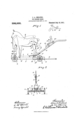
- Figure l is a view in side elevation with some parts sectioned, showing the improved toy; and Fig. 2 is a view partly in rear elevation and partly in transverse vertical section on the line 512 m of Fig. 1.
- the toy comprises a truck with a toy horse, and an inclined runway applied thereto, and with the horse arranged to kick a toy cart truck or other traveling object off from the said inclined runway.
- the numeral 1 indicates the platform, and the numeral 2 the wheels of the main truck which carries the kicking horse and runway.
- the inclined runway is preferably in the form of a chute 3, the upper end of which is approximately horizontal and the lower end of which is detachably interlocked to an inclined holding bracket 4 on the platform 1.
- the lower portions of the runway 3 and the intermediate portion of the bracket 41- are cut away to afford clearance for an upwardly spring pressed latch plate 5, the forwardly projecting prongs of which, as shown, are attached at 6 to a raised bar 7 on the platform 1.
- the figure or part which represents the toy horse is preferably formed from sheet metal and the body 8 thereof, is provided with rigidly secured front legs 9 and a pair of hind legs 10.
- the front legs 9 are pivotally attached at their lower ends at 11 to the front portion of the platform bar 7 and the rear legs 10 are pivotally attached by a bolt 12 to the body 8.
- the said hind legs 10 are preferably connected by a spacing thimble and rivet 13 so that they will be given common pivotal movements, and near their lower or foot ends, are provided with latch lugs or shoulders 14 that are adapted to be engaged under the front edge of the latch plate 5.
- a spring 15 is coiled around the pivot bolt 12 and one end anchored to the body 8, and its other end anchored to one of the rear legs 10.
- An operating cord or flexible connection 16 is attached to the foot of one of the rear legs 10 and is passed downward through perforations in the platform 1, and thence, rearward through a guide eye 17 on the rear end of said platform.
- the head or front portion of the body 8 is yieldingly drawn downward, preferably, by a coiled spring 18 attached thereto and to a toy figure 19 which represents a man or boy and which is anchored or rigidly secured to the front portion of the platform 1.
- the numeral 20 indicates a small cart or truck which is adapted to be run by gravity downward on the runway 3 and which is provided with a forwardly projecting trip plate 21 that is adapted to strike the rear legs 10 of the toy horse, just above the latch plate 5. As shown, the toy representation of a man or boy is applied on the cart 20.
- the detachable connection between the lower end of the runway 3 and the bracket 4E is, as shown, made by laterally spaced lugs 23 on the ends of said runway, which are adapted to enter perforated keepers 24: on the sides of said bracket 4:.
- a suitable draw cord 25 is preferably attached to the front end of the platform 1 so that the entire device may be drawn over the floor.
- the operation of the improved toy is sub stantially as follows:
- the toy horse is drawn downward and latched in a position indicated by full lines in Fig. 1.
- the latch shoulders 14 of the rear legs 1.0 are engaged with the latch plate 5 so that the horse is held in normal position, as stated, against the tension of both of the springs 15 and 18.
- the tripping cart 20 being then placed at the top of the runway, allowed to run downward thereon by gravity, its trip plate 21 will engage the lower ends of the legs 10 and press the same slightly forward against the tension of the spring 15, thereby releasing the said legs from the latch tripping plate 5.
- the toy described affords great amusement for children and others, furthermore, may be constructed and sold at small cost.
- the runway 3 may be easily lifted out of the bracket 4.
- a figure of a horse a figure of various other animals may be employed, and instead of the socalled tripping cart, other objects arranged to travel the .inclined runway or chute, may be employed.
Landscapes
- Toys (AREA)
Description
J. A. EKELUND.
TOY KIGKING HORSE.
P11101110! 111.1111 um. 21, 1910.
998,566, Patented July 18, 1911.
OOLUMIIA PLANOORAPH DP" WASHINGTON, D, C.
UNITED STATES PATENT OFFICE.
JOHN A. EKELUND, OF MINNEAPOLIS, MINNESOTA, ASSIGNOR OF ONE-HALF TO JAMES F. WILLIAMSON, OF MINNEAPOLIS, MINNESOTA.
TOY KICKING HORSE.
Specification of Letters Patent.
Application filed September 21, 1910.
To all whom it may concern:
Be it known that I, JOHN A. EKELUND, a citizen of the United States, residing at Minneapolis, in the county of Hennepin and State of Minnesota, have invented certain new and useful Improvements in Toy Kicking Horses; and I do hereby declare the fol lowing to be a full, clear, and exact description of the invention, such as will enable others skilled in the art to which it appertains to make and use the same.
My invention has for its object to provide an improved toy, and to this, end the invention consists of the novel devices and combinations of devices hereinafter described and defined in the claims.
In the accompanying drawings which illustrate the invention, like characters indicate like parts throughout the several views.
Referring to the drawings: Figure l is a view in side elevation with some parts sectioned, showing the improved toy; and Fig. 2 is a view partly in rear elevation and partly in transverse vertical section on the line 512 m of Fig. 1.
As preferably designed, the toy comprises a truck with a toy horse, and an inclined runway applied thereto, and with the horse arranged to kick a toy cart truck or other traveling object off from the said inclined runway.
The numeral 1 indicates the platform, and the numeral 2 the wheels of the main truck which carries the kicking horse and runway. The inclined runway is preferably in the form of a chute 3, the upper end of which is approximately horizontal and the lower end of which is detachably interlocked to an inclined holding bracket 4 on the platform 1. The lower portions of the runway 3 and the intermediate portion of the bracket 41- are cut away to afford clearance for an upwardly spring pressed latch plate 5, the forwardly projecting prongs of which, as shown, are attached at 6 to a raised bar 7 on the platform 1.
The figure or part which represents the toy horse is preferably formed from sheet metal and the body 8 thereof, is provided with rigidly secured front legs 9 and a pair of hind legs 10. The front legs 9 are pivotally attached at their lower ends at 11 to the front portion of the platform bar 7 and the rear legs 10 are pivotally attached by a bolt 12 to the body 8. The said hind legs 10 are preferably connected by a spacing thimble and rivet 13 so that they will be given common pivotal movements, and near their lower or foot ends, are provided with latch lugs or shoulders 14 that are adapted to be engaged under the front edge of the latch plate 5. A spring 15 is coiled around the pivot bolt 12 and one end anchored to the body 8, and its other end anchored to one of the rear legs 10. An operating cord or flexible connection 16 is attached to the foot of one of the rear legs 10 and is passed downward through perforations in the platform 1, and thence, rearward through a guide eye 17 on the rear end of said platform. The head or front portion of the body 8 is yieldingly drawn downward, preferably, by a coiled spring 18 attached thereto and to a toy figure 19 which represents a man or boy and which is anchored or rigidly secured to the front portion of the platform 1.
The numeral 20 indicates a small cart or truck which is adapted to be run by gravity downward on the runway 3 and which is provided with a forwardly projecting trip plate 21 that is adapted to strike the rear legs 10 of the toy horse, just above the latch plate 5. As shown, the toy representation of a man or boy is applied on the cart 20.
The detachable connection between the lower end of the runway 3 and the bracket 4E is, as shown, made by laterally spaced lugs 23 on the ends of said runway, which are adapted to enter perforated keepers 24: on the sides of said bracket 4:. A suitable draw cord 25 is preferably attached to the front end of the platform 1 so that the entire device may be drawn over the floor.
The operation of the improved toy is sub stantially as follows: The toy horse is drawn downward and latched in a position indicated by full lines in Fig. 1. Preferably by taking hold of the cord 25 in one hand and the cord 16 with the other hand, and drawing rearward on the latter while holding the truck against movement by the former. In this way the latch shoulders 14 of the rear legs 1.0 are engaged with the latch plate 5 so that the horse is held in normal position, as stated, against the tension of both of the springs 15 and 18. The tripping cart 20 being then placed at the top of the runway, allowed to run downward thereon by gravity, its trip plate 21 will engage the lower ends of the legs 10 and press the same slightly forward against the tension of the spring 15, thereby releasing the said legs from the latch tripping plate 5. Then the rear legs are thus released from the latch plate, the springs 15 and 18 will simultaneously act and the former will impart a rearward kicking movement to the said legs, simultaneously with a movement of the body 8 forward and upward into position indicated by dotted lines in Fig. 1. This movement very closely approximates the movement of a kicking horse and the rear and upward movement of the rear legs acting against the tripping plate 21 of the said cart will kick the latter backward and upward and ofi from the runway. The tripping cart kicked into the air in the manner stated is indicated by dotted lines in Fig. l.
The toy described affords great amusement for children and others, furthermore, may be constructed and sold at small cost.
For the purposes of shipment and storage the runway 3 may be easily lifted out of the bracket 4. As is evident, instead of a figure of a horse, a figure of various other animals may be employed, and instead of the socalled tripping cart, other objects arranged to travel the .inclined runway or chute, may be employed.
What I claim is:
1. The combination with a support, of a body having a rigid front leg and a pivoted rear leg, the said front leg being pivotally attached to said support at its lower end, a yielding connection between said body and support tending to raise the rear portion thereof, an independent yielding device tending to swing said rear leg rearward and upward, a latch for securing said rear leg in a downward and forwardly drawn position, and means for releasing said latch to produce the kicking movement.
2. The combination with a support and an inclined runway, of a body having front legs pivotally connected to said support and provided with pivoted rearwardly spring pressed rear legs, yielding means tending to draw the front end portion of said body downward, a latch at the lower portion of said runway engageable with said rear legs to hold the same drawn downward and forward and a device adapted to travel loosely on said runway and to engage the said pivoted rear legs and disengage the same from said latch, to thereby produce a kicking movement, substantially as described.
3. The combination with a support and an inclined runway detachably connected thereto, of a body having front legs pivoted. to said support and provided with rearwardly spring pressed pivoted rear legs with latch shoulders, a spring yieldingly drawing downward on the front portion of said body, a latch applied to said support at the lower portion of said runway and engage able with the shoulders of said rear legs, a flexible connection to said rear legs guided by the said plat-form and adapted, when pulled upon, to engage the latch shoulders of said rear legs with said latch, and a. trip ping cart movable on said runway and provided with a forwardly projecting tripping plate engageable with said rear legs to disengage the same from said latch, substantially as described.
In testimony whereof I aflix my signature in presence of two witnesses.
JOHN A. EKELUND.
Witnesses BERNIOE G. WHEELER, HARRY D. KILGORE.
Copies of this patent may be obtained for five cents each, by addressing the Commissioner of Patents, Washington, D. C.
Priority Applications (1)
| Application Number | Priority Date | Filing Date | Title |
|---|---|---|---|
| US58299410A US998566A (en) | 1910-09-21 | 1910-09-21 | Toy kicking horse. |
Applications Claiming Priority (1)
| Application Number | Priority Date | Filing Date | Title |
|---|---|---|---|
| US58299410A US998566A (en) | 1910-09-21 | 1910-09-21 | Toy kicking horse. |
Publications (1)
| Publication Number | Publication Date |
|---|---|
| US998566A true US998566A (en) | 1911-07-18 |
Family
ID=3066894
Family Applications (1)
| Application Number | Title | Priority Date | Filing Date |
|---|---|---|---|
| US58299410A Expired - Lifetime US998566A (en) | 1910-09-21 | 1910-09-21 | Toy kicking horse. |
Country Status (1)
| Country | Link |
|---|---|
| US (1) | US998566A (en) |
-
1910
- 1910-09-21 US US58299410A patent/US998566A/en not_active Expired - Lifetime
Similar Documents
| Publication | Publication Date | Title |
|---|---|---|
| US998566A (en) | Toy kicking horse. | |
| US563066A (en) | Trolley for kites | |
| US2525377A (en) | Toy horse swing | |
| US243439A (en) | Climbing or traveling toy | |
| US1216632A (en) | Figure toy or amusement device. | |
| US396221A (en) | m morrow | |
| US557756A (en) | William earth | |
| US877504A (en) | Apparatus for breaking or training animals. | |
| US2022861A (en) | Mechanical toy | |
| US1272395A (en) | Toy cart. | |
| US2244447A (en) | Combined wheeled toy and exercising device | |
| US2727741A (en) | Animated rocking horse | |
| US1556090A (en) | Child's vehicle | |
| US2783585A (en) | Wheeled horse and rider | |
| US1411737A (en) | Figure wheeled toy | |
| US362238A (en) | Island | |
| US1024314A (en) | Figure toy. | |
| US903448A (en) | Traveling rocking-horse. | |
| US871701A (en) | Toy. | |
| US214615A (en) | Improvement in toys | |
| US1892561A (en) | Toy | |
| US2029849A (en) | Walking toy | |
| US2252016A (en) | Walking hobbyhorse | |
| US808959A (en) | Game apparatus. | |
| US1294128A (en) | Figure toy. |